

TITech M4 Controller
v.1.2
ユーザーマニュアル
User manual
www.hibot.co.jp+

!2
HiBot Corporation TITech M4 Controller
®
User Manual
HB-UM-M4CTRL

目次/Table+of+contents+
はじめに/Introduction 4..........................................................................................
製品概要 4..............................................................................................................
定格/Electrical characteristics 4.....................................................................
外観/Board dimensions 5...............................................................................
コネクタ一覧/Connectors and housing 6......................................................
機能説明 / Features 7.............................................................................................
ホールセンサ入力 / Schematic block 7..........................................................
CAN ports 7................................................................................................
Accelerometer and Magnetometer 8..............................................................
Gyroscope 9...................................................................................................
LAN port 10....................................................................................................
MicroSD port 12.............................................................................................
LEDs 13.........................................................................................................
A/D and D/A Ports 13.....................................................................................
Digital Input/Output and timer ports 13..........................................................
放熱 / Installation of the board and dissipation 14..................................................
コネクタのピン/Pin assignment 15....................................................................
■保証 16.........................................................................................................
Warranties and conditions 17.................................................................................

!4
HiBot Corporation TITech M4 Controller
®
User Manual
はじめに/Introduction
This manual introduces the HiBot Titech M4 Controller ® board.
HiBot Titech M4 Controller board is based on the STM32TM ARM Cortex M4
STM32F407IG. For detailed chip hardware manuals, user is requested to check the
documentation available online on the chip maker STMicroeletronics.
製品概要
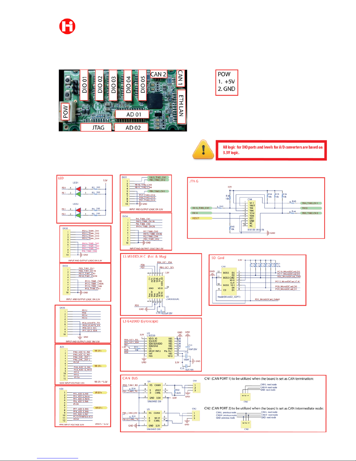
Supply voltage is of 5V and the board; digital input are 5V compliant, however all A/D inputs
and the board functionalities are based on 3.3V voltage and logic levels. An input voltage higher
than 3.3V on any analog channel would permanently damage the board. Thus digital output and
D/A outputs will be delivering maximum 3.3V.
定格/Electrical characteristics
Table 1
HB-UM-M4CTRL
Parameter
Conditions
Supply voltage
5V
CPU Osc. Frequency
168MHz
Continuous current consumption
0.6A
Voltage logic level
3.3V

!5
HiBot Corporation TITech M4 Controller
®
User Manual
外観/Board dimensions
図/Figure 1 - Titech M4 Controllerの外観/Titech M4 Controller
図/Figure 2 – Titech M4 Controllerの寸法図/Titech M4 Controller dimensions
HB-UM-M4CTRL
!6
HiBot Corporation TITech M4 Controller
®
User Manual
コネクタ一覧/Connectors and housing
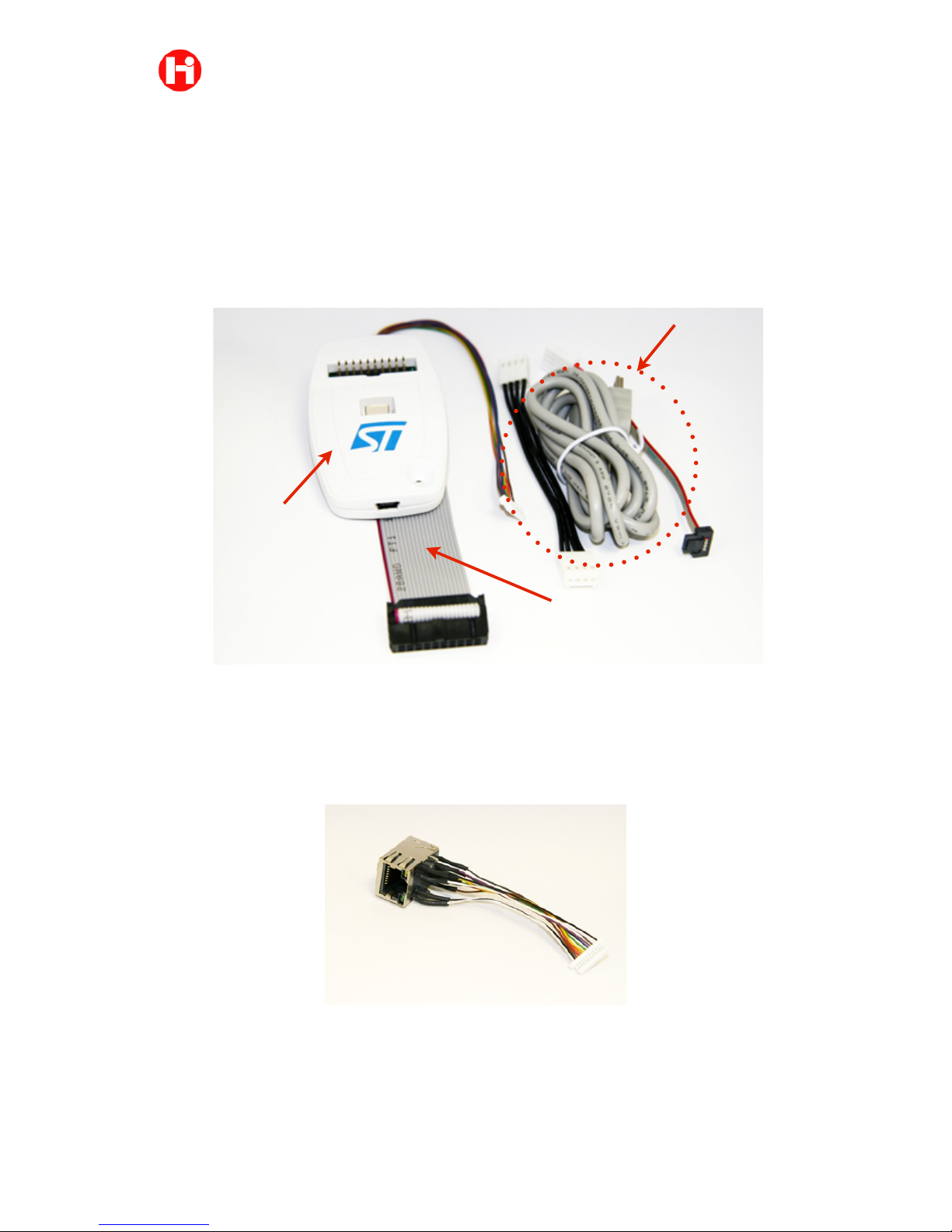
The board is supplied with JTAG cable, shown in Figure 3, it can be utilized in
connection with any debugger programmer for STM32 cores. This documentation will
refer to the debugger/programmer device ST-LINK/V2 which is also available from the
HiBot e-shop.
Figure 3 - JTAG cable and ST-LINK/V2 programmer
Optional cable, also available online, is the LAN transceiver RJ45 connector, shown
in Figure 4
Figure 4 - LAN cable with RJ45 transceiver
HB-UM-M4CTRL
JTAG cable
ST-LINK/V2
ST-LINK/V2
cable set
!7
HiBot Corporation TITech M4 Controller
®
User Manual
The board utilizes JST housing and connectors as follows:
-Housing: PHR-2 (for power), SHR-xV-S-B or SHR-xV-S (where x is 10,12 or 3
according the port user wishes to use)
-Contact: SPH-002T-P0.5S; SSH-003T-P0.2
機能説明 / Features
ホールセンサ入力/ Schematic block
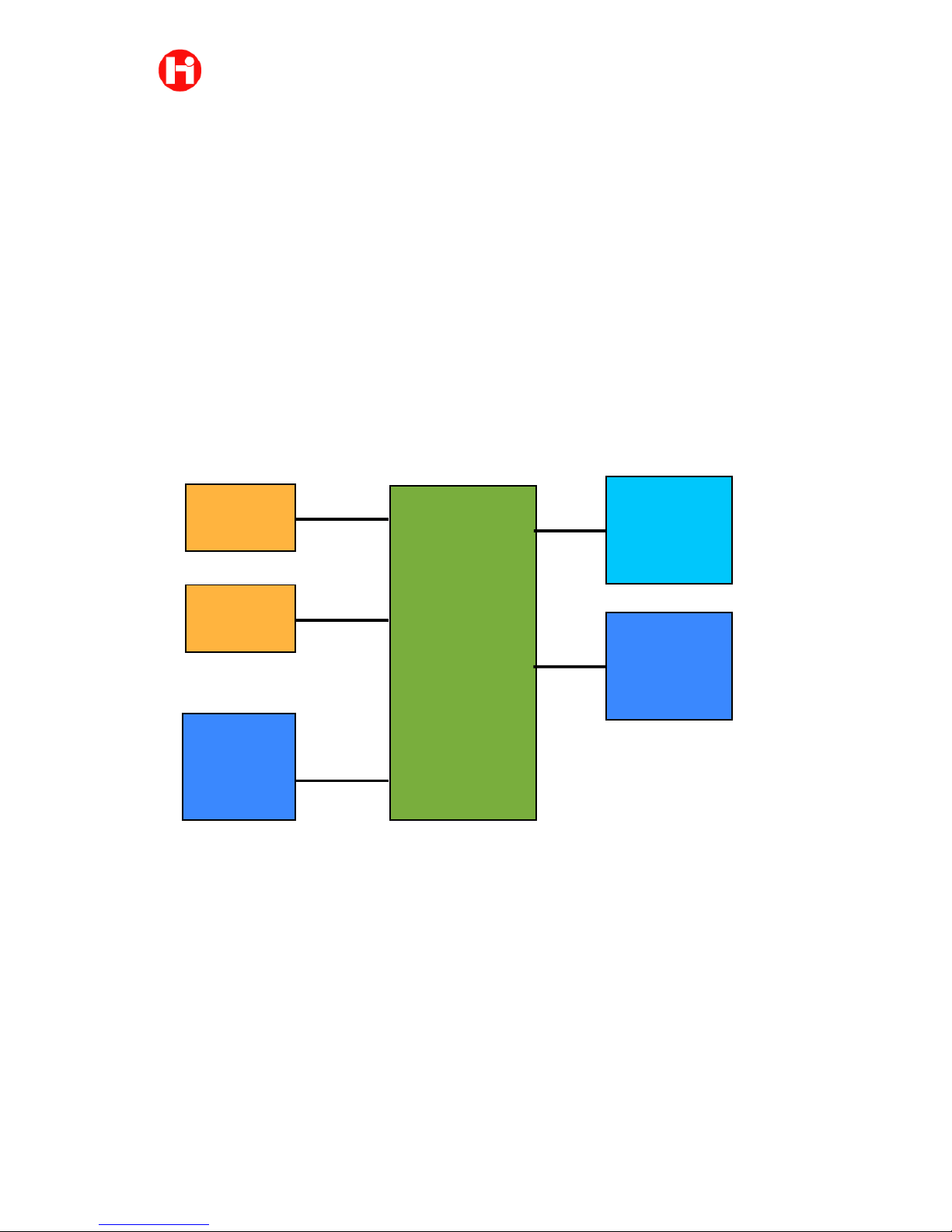
Figure 5 - Board schematic block
Titech M4 Controller is equipped with on board motion sensor unit consisting of a digital
accelerometer and magnetometer LSM303DLHC and the Gyroscope L3GD20. Connectivity to
other devices can be carried out not only by UART but also utilizing two CAN ports and/or
LAN ethernet communication.
CAN ports
Two CAN ports are available, CAN port 1 is set on-board with its termination thus it can be
utilized when the board is set as a termination as shown in Figure 6. CAN2 port should be
instead used when the board will be utilized as a network node, the cable will have to be split in
order to serialize the board in the network as shown in Figure 7
HB-UM-M4CTRL
!"#$%&#'
())&*&#+,-&
./0.12&
3!#&$4$5367
8921.)1:/&
3$85%445
7(;&&
"2+0.)/<=/2
7(;&&
"2+0.)/<=/2
7(;&>
7(;&%
?%7
?%7
3(;&<0@/2A+)/

!8
HiBot Corporation TITech M4 Controller
®
User Manual
Figure 6 - CAN port 1 utilized as a termination
Figure 7 - CAN port 2 utilized as a network node
Titech M4 Controller can be utilized as a master or as a node together with other HiBot
micro controller based boards
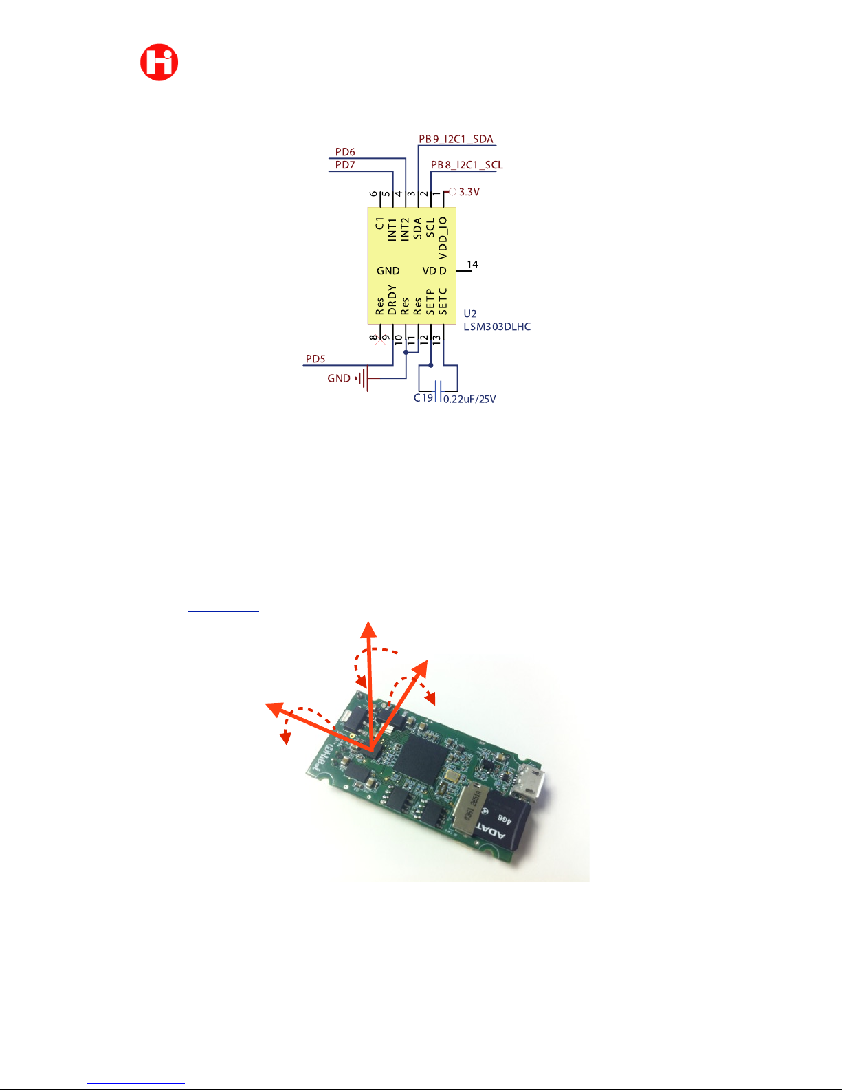
Accelerometer and Magnetometer
For more details on the accelerometer and magnetometer user should refer to the
documentation available online on the LSM303DLHC chip maker.
Figure 8 shows the orientation of the chip installed on the bottom side of the board
with the direction of the detectable magnetic field and accelerations.
Figure 8 - Directions of the detectable acceleration and magnetic fields
The chip can be accessed through the I2C port connected to PB9 and PB8 pins of
the micro-controller as shown in Figure 9
HB-UM-M4CTRL
Y
YXZ
!9
HiBot Corporation TITech M4 Controller
®
User Manual
Figure 9 - Accelerometer and Magnetometer on board.
Gyroscope
Figure 10 shows the orientation of the gyroscope which is installed in the bottom
layer of the board. The chip supplies also temperature measurements that might be
utilized for precise adjustments due to the environment temperature. For more details on
the chip characteristics user is requested to access the documentation online available
on the L3G4200D maker.
Figure 10 - Directions of the detectable angular rates
HB-UM-M4CTRL
YXZ

!10
HiBot Corporation TITech M4 Controller
®
User Manual
The chip can be accessed by the I2C connected to PB8 and PB9 pins of the micro
controller as shown in the following Figure 11.
Figure 11 - Gyroscope on board.
LAN port
The board offers the possibility to utilize Ethernet LAN communication through the
LAN port. Figure 12 shows the LAN interface and the pin assignment to the microcontroller.
HB-UM-M4CTRL
1
2
3
4
MCO
GND
PD5
GND
GND
PD7
PD6
3.3V
3.3V
3.3V
PB8_I2C1_SCL
PB9_I2C1_SDA
3.3V
GND
GND
GND
GND
GND
GND
PD8
PD9
PB7
PB8_I2C1_SCL
PB9_I2C1_SDA
3.3V
3.3V
LSM303DLHC (Acc a Mag)
L3GD20 (Gyroscope)
One decoupling Cap for each VDD(totally 14 100nF)
PA0_ADC12_IN0
PA3_ADC12_IN3
PA4_DAC_OUT1
PA5_DAC_OUT2
PA6_ADC12_IN6
VDD_IO
1
SCL
2
SDA
3
INT24INT1
5C16
GND
7
Res8DRDY9Res10Res11SETP12SETC
13
VDD
14
U2
LSM303DLHC
0.22uF/25V
C19
100nF
C17
10uF/10V
C18
10nF/25V
C21
VDD_IO
1
SCL/SPC
2
SDA/SDI/SDO
3
SDO/SA0
4
CS
5
DRDY/INT2
6
INT
7
RES
8
RES
9
RES
10
RES
11
RES
12
GND
13
PLLFILT
14
RES
15
VDD
16
U3
L3GD20
100nF
C20
100nF
C22
10uF/10V
C23
10k
R11
100nF
C1
100nFC2100nFC6100nFC7100nFC8100nFC9100nF
C10
100nF
C3
100nF
C11
2.2k
R12
2.2k
R13
10k
R10
GND
PA2_MI I_MDIO
PA7_MI I_RX _DV
PA1_MI I_RX _CLK
PA10_OTG_FS_ID
PA9_OTG_FS_VBUS
PA11_OTG_FS_DM
PA12_OTG_FS_DP
PA15_TIM2_CH1
PA13
PA14
PB0_TIM3_CH3
PB1_TIM3_CH4
PB3_TIM2_CH2
PB4_TIM3_CH1
PB5_CAN2_RX
PB7
PB8_I2C1_SCL
PB9_I2C1_SDA
PB10_TIM2_CH3
PB11_TIM2_CH4
PB12
100k
R7
100k
R8
100k
R9
3.3V
100kR14
100k
R15
3.3V
DFU
DFU
DFU
0
R6
4.7uF/10V
C16
MII_RX_CLK
1
2
JP2
0Hom Resistor
1
2
JP4
Jumper(2 pads)
470nF
C48
10k
R1
PB13_CAN2_TX
PB6
PIC101
PIC102
COC1
PIC201
PIC202
COC2
PIC301
PIC302
COC3
PIC601
PIC602
COC6
PIC701
PIC702
COC7
PIC801
PIC802
COC8
PIC901
PIC902
COC9
PIC1001
PIC1002
COC10
PIC1101
PIC1102
COC11
PIC1201
PIC1202
PIC1601
PIC1602
COC16
PIC1701
PIC1702
COC17
PIC1801
PIC1802
COC18
PIC1901 PIC1902
COC19
PIC2001
PIC2002
COC20
PIC2101
PIC2102
COC21
PIC2201PIC2202
COC22
PIC2301PIC2302
COC23
PIC4801
PIC4802
COC48
PIJP201 PIJP202
COJP2
PIJP401PIJP402
COJP4
PIR101
PIR102
COR1
PIR601 PIR602
COR6
PIR701 PIR702
COR7
PIR801 PIR802
COR8
PIR901 PIR902
COR9
PIR1001 PIR1002
COR10
PIR1101
PIR1102
COR11
PIR1201
PIR1202
COR12
PIR1301
PIR1302
COR13
PIR1401 PIR1402
COR14
PIR1501PIR1502
COR15
PIU201
PIU202PIU203PIU204PIU205
PIU206
PIU207
PIU208
PIU209
PIU2010 PIU2011 PIU2012
PIU2013
PIU2014
COU2
PIU301
PIU302
PIU303
PIU304
PIU305
PIU306
PIU307
PIU308
PIU309
PIU3010
PIU3011
PIU3012
PIU3013
PIU3014
PIU3015
PIU3016
COU3
PIC102 PIC202
PIC302
PIC902
PIC1002
PIC1102 PIC1202 PIC1302PIC1402 PIC1502
PIC1701 PIC1801
PIC2001
PIC2202
PIC2302
PIR701
PIR801
PIR901
PIR1101
PIR1202 PIR1302
PIR1401
PIR1502
PIU201
PIU2014
PIU301
PIU3015
PIU3016
PIC101 PIC201
PIC301
PIC901
PIC1001
PIC1101 PIC1201 PIC1301PIC1401 PIC1501
PIC1602
PIC1702 PIC1802
PIC2002
PIC2102
PIC2201
PIC2301
PIR102
PIR1001
PIU207
PIU2010 PIU2011
PIU308
PIU309
PIU3010
PIU3011
PIU3012
PIU3013
PIR602
NLMCO
PIC1601
PIU206
PIC1901
PIU2012
PIC1902
PIU2013
PIC2101
PIC4801
PIU3014
PIC4802
PIR101
PIJP201
PIJP402
PIJP202
POMII0RX0CLK
PIJP401
PIR601
POPA10MI I0RX 0CLK
PIR702
POPA100OTG0FS0ID
PIR802
POPA110OTG0FS0DM
PIR902
POPA120OTG0FS0DP
PIR1002
PIR1102
PIU305
POPA14
POPA13
POPA90OTG0FS0VBUS
POPA20MI I0MDIO
POPA70MI I0RX 0DV
PIU208
PIR1402
PIU304
NLPB7
PIR1301
PIU202
PIU302
NLPB80I2C10SCL
PIR1201
PIU203
PIU303
NLPB90I2C10SDA
PIR1501
NLPB130CAN20TX
PIU209
PIU204
PIU205
PIU306
PIU307
POMII0RX0CLK
POPA10MI I0RX 0CLK
POPA20MI I0MDIO
POPA70MI I0RX 0DV
POPA90OTG0FS0VBUS
POPA100OTG0FS0ID
POPA110OTG0FS0DM
POPA120OTG0FS0DP
POPA13
POPA14
POPA150TIM20CH1
POPB30TIM20CH2
POPB40TIM30CH1

!11
HiBot Corporation TITech M4 Controller
®
User Manual
Figure 12 - LAN interface
User can make use of the cable offered on HiBot homepage depicted in Figure 4 or
can assemble a cable with transceiver following the schematics available in Figure 13
HB-UM-M4CTRL
a

!12
HiBot Corporation TITech M4 Controller
®
User Manual
Figure 13 - Connection between LAN port and RJ45 transceiver
MicroSD port
Figure 14 shows the connection to the microcontroller pins of the microSD card
reader.
Figure 14 - MicroSD adapter pin connetions
HB-UM-M4CTRL
LED_SPEED-
TD-
TD+
RD+
RD-
LED_LINK+
LED_SPEED+
CT
CT
GND
LED_LINK-
M4 board CN7
JST SHR-12V-S-B
(HiBot HB-SHR12-001)
RJ45 with transformer
TAIMAG RJLD-260TC1
CN7
CN12P_1
12
11
10
9
8
7
6
5
4
3
2
1
CN?
CN12P_1
1
2
3
4
5
6
7
8
9
10
11
12

!13
HiBot Corporation TITech M4 Controller
®
User Manual
LEDs
A total of four LEDs are available on board. User can access them by setting as
digital output pins PE0, PE1, PE3 and PE4 as shown in Figure 15.
When the correspondent digital out pin is set as low level, the respective LED will
be switched on.
Figure 15 - Pin assignment for the LEDs
A/D and D/A Ports
All A/D channels are maximum 3.3V tolerant. An input voltage higher than 3.3V on
any analog channel would permanently damage the board. When using potentiometers, user
should make use of the available VREF+ (3.3V) for power and of VSSA (GND) for
ground signal that are shown in the pin assignment section of this manual. All channels
are with 12 bit resolution.
Two Digital to Analog converter pins are also available at the AD1 pin 4 (PA4) and
pin 5 (PA5); both lines will be outputting a signal between 0 to 3.3V.
Digital Input/Output and timer ports
All digital Input/Output pins available are depicted in the pin assignment section at
the end of this manual. Each pin can be configured according to its possible functions
(please refer to the STM32F407IG user manual for more information).
HB-UM-M4CTRL
BC5
8BCC;
BC5
8BCC;

!14
HiBot Corporation TITech M4 Controller
®
User Manual
放熱 / Installation of the board and dissipation
When installing the board for applications, the holes available on the board should
be utilized taking care of avoiding any contact of the board surfaces with conductive
materials.
HB-UM-M4CTRL
!15
HiBot Corporation TITech M4 Controller
®
User Manual
コネクタのピン/Pin assignment
HB-UM-M4CTRL

!16
HiBot Corporation TITech M4 Controller
®
User Manual
■保証
-1- 保証期間
株式会社ハイボットは、本製品を納入日から6か月間にわたり保証いたします。
-2- 保証の制限
■修理の制限
株式会社ハイボットの責に帰する不具合が保証期間内に生じた場合、瑕疵のある当該製品
を直ちに修理または交換させていただきます。ユーザサポートは、本保証における救済に含ま
れません。
■損害の制限
本保証は、瑕疵のある製品のみに適用され、かかる製品の故障から生じるその他のいかな
る損害にも適用されません。
本製品の損傷が以下のいずれかに起因する場合、本保証は適用されません。
1) 購入者による不適切な取り扱い/使用
2) 購入者による他の工具/機械の使用
3) 第三者による変更/修理
4) 何らかの自然災害/人為災害
■保証に関するその他の制限事項
株式会社ハイボットは、本製品の瑕疵に起因する通常損害、派生損害、付随的損害、また
は特別損害に対していかなる責任も負いません。また、本製品の不適切な使用または改造によ
る本製品の不具合または損傷についても、かかる使用または改造により第三者にもたらされ得
る不具合または損傷についても、一切の保証をいたしません。さらに、本製品にインストール
されたデータの偶発的な喪失につき、いかなる保証もいたしません。
本製品および付属ドキュメントは、現状有姿のまま提供され、その特定目的適合性に関し
て、いかなる保証も行われず、また、暗示されるものでもありません。本製品の使用または故
障の結果として生じた損害賠償請求に対し、株式会社ハイボットは一切応じないものとしま
す。
本製品またはその改良型は、本製品の故障によって人身障害が起こることが合理的に予想
される任意の医療器具、医療装置、または医療システムにおける使用が意図されたものではあ
りません。
このドキュメントは予備情報を提供するものであり、かかる情報は予告なく変更されるこ
とがあります。
株式会社ハイボット
〒153-0064 東京都目黒区下目黒2-18-3"
目黒第一花谷ビル801
TEL: +81-(0)3-6420-0445
FAX : +81-(0)3-6420-0446
http://www.hibot.co.jp
HB-UM-M4CTRL

!17
HiBot Corporation TITech M4 Controller
®
User Manual
Warranties and conditions
-1- Warranty Period
HiBot Corporation ® guarantees the product for 6 months from the date of delivery.
-2- Warranty Limitations
■Limitation of Repair
For any failure attributable to HiBot Corporation ® within the period of Warranty, the
defective product will be promptly repaired or replaced. User assistance is not included in
the Warranties remedies.
■Limitation of Damages
Warranties will be applied only to the defective product itself, and not to any other
damage caused by the breakdown of the defective product.
Warranties do not apply to damages of the product caused by:
1) Inappropriate handling or using by the Buyer.
2) The use of any other tool or machinery by the Buyer.
3) Modifications or repair by third parties.
4) Any natural or artificial disaster.
■Additional Limitations on Warranty
Hibot Corp. has no liability for general, consequential, incidental or special damages
arising from a defect in the product. HiBot does not warrantee regarding possible
malfunctions or damages of the board and to third parties that may result from an
improper use or alterations of the board. Furthermore HiBot Corporation does not
warrantee regarding an eventual loss of data installed on the board.
This product and its documentation are supplied on an as-is basis and no warranty as
to their suitability for any particular purpose is either made or implied. HiBot Corp. will
not accept any claim for damages however arising as a result of use or failure of this
product.
This product or any variant of it is not intended for use in any medical appliance, device
or system in which the failure of the product might reasonably be expected to result in
personal injury.
This document provides preliminary information that may be subject to change without
notice.
Last Revision: August 16
th
2017 (updated CAN pin order)
All informations, representations, links or other messages may be changed by HiBot at any time
without prior notice or explanation to the user. In particular, HiBot is not obliged to remove any
outdated information from its website or to expressly mark it as being outdated.
HB-UM-M4CTRL
 Loading...