

Page 1
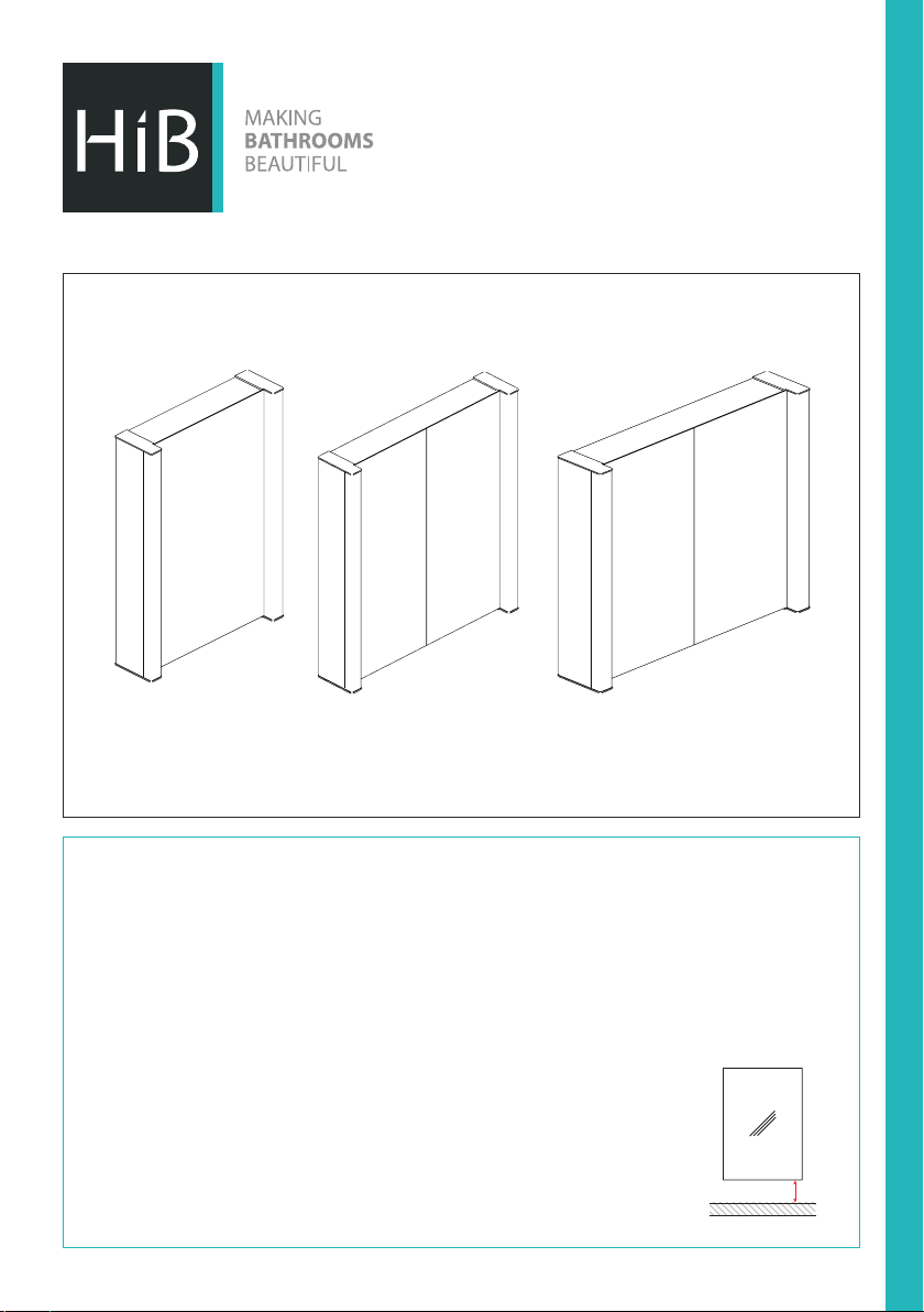
Velocity, Photec & Vector Cabinets
Velocity
Art No. 43100
Photec
Art No. 43200
Vector
Art No. 44400
Thank you for purchasing this HiB product.
Please read through these instructions carefully and refer back to them during installation to ensure that
your product is tted safely and that it retains its high quality nish.
Please retain this leaet for future reference.
Before drilling, ensure there are no hidden cables or pipes in the wall.
Please Note You may need to remove the door(s) to aid installation. This can be done by unclipping the
hinges. (There is a release catch at the back of the hinge).
DO NOT FIT SHELVES AT THIS STAGE.
Please do not lift the product up by the plastic diusers as this may cause damage
to your product.
These products must be installed with a minimum distance of 150mm between
the infra-red sensor switch and any surface or object to ensure correct operation
of the sensor.
FI #02 006 R150908 Ver No. 1.0 Jan 2016
Min. 150mm
Page 2
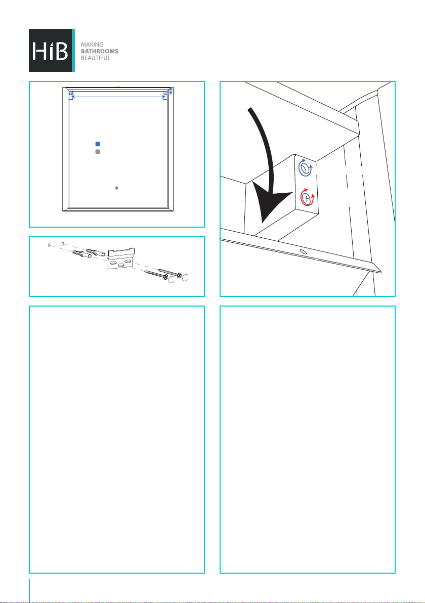
REAR VIEW
Mounting Points
location of internal
fixing hole
Fixing Preparation (Fig A)
Angle Adjustment
Claw In/Out
Claw In/Out
Adjustment
Adjustment
Fixing Brackets (Fig B)
Wall Hung Installation
1. Position the cabinet in a suitable location
(according to the zonal diagram (Fig 1) on
the back page) ensuring that the mains
supply cable is within reach of the cable
connection point of the cabinet. Carefully
mark the desired position of the cabinet
using a soft pencil, ensuring it is level.
2. Remove the cabinet from the wall and
using a spirit level, mark a horizontal line
below the pencil mark, taking into account
the location of the mounting points (Fig.
A). Place brackets on the new line paying
attention to the distance between the
hangers on the cabinet. Carefully mark the
position of the holes using a soft pencil.
(Fig. B).
3. Before drilling, ensure there are no hidden
cables or pipes behind the mounting point.
Using a suitable drill bit, drill holes in the
marked positions to a suitable depth.
4. Insert wall plugs level with the surface of the
wall. If tting to a tiled surface, wall plugs
should be inserted below the tile surface to
avoid cracking. NB. For plasterboard walls,
Hanger Adjustment (Fig C)
specialist xings should be purchased from any
DIY or hardware store.
5. Fix the brackets to the wall using the screws
provided.
6. Carefully remove the small screws along the
top front edge of the cabinet to gain access
to the internal panel(s). (Fig. C) Keep screws
in a safe place.
7. Temporarily hang the cabinet ensuring the
claws on the hangers are securely located on
the wall brackets. Using a spirit level adjust
the cabinet via the screws on the hangers.
8. Mark the position of the internal xing hole
and remove the cabinet. Using a suitable drill
bit, drill a hole and insert a wall plug as per
stage 4.
9. Connect the cable at the rear of the cabinet
to the mains supply cable using a suitable
terminal block (not supplied) according to
the wiring diagram (Fig. 2) on the back page.
10. Rehang the cabinet in position, tighten the
screws on the hangers (Fig. C) and secure the
base of the cabinet with the supplied screw
and screw cap.
2
Page 3
11. Once fully secure, close the internal panel(s)
using the screws removed at stage 6.
12. Fit shelves in desired positions using metal
shelf supports.
13. Reattach the door(s) ensuring the hinges
fully locate and click back into position.
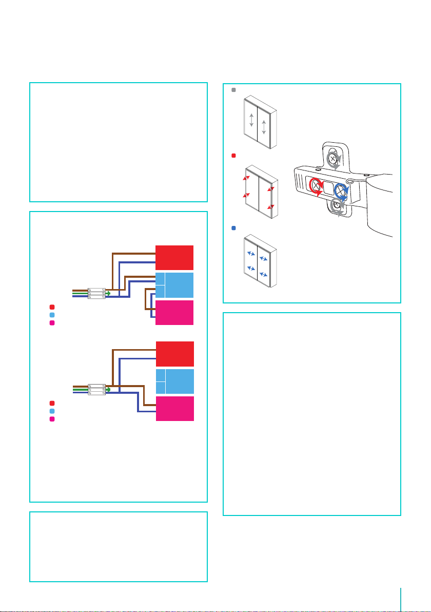
14. If necessary, the hinges can be adjusted in
order to reposition the door(s) (Fig.D).
15. Switch the mains supply back on.
Move door(s) up/down
Move door away/towards
the cabinet
How to Isolate the sensor so you can
switch ON & OFF with a mains switch.
How the cabinet is wired.
live
earth
neutral
Shaver socket/transformer
Sensor switch controller
LED driver
How to isolate the sensor.
live
earth
neutral
Shaver socket/transformer
Sensor switch controller
LED driver
Rewire the cabinet as shown in the diagram
above. HiB recommends that all electrical
bathroom products should only be tted by a
suitably qualied, Part P registered electrician.
For further assistance on isolating the sensor
please contact us.
Tel: 020 8441 0352 Email: [email protected]
INOUT
INOUT
Move door(s) left/right
Door Adjustment (Fig D)
Lamp Replacement
Requires 2x T4 Lamps, Max 22W
CAUTION: The surface of the Lamp may
become extremely hot! Allow at least 30
minutes afterlamp failure before replacing...
1. Turn o the mains electrical supply.
2. Unscrew the two screws on top of the
chrome luminaire cap and slide translucent
cover upwards.
3. Carefully grasp the failed lamp and rotate 90°
anti-clockwise to remove the lamp from the
lamp holder.
4. Carefully push the replacement lamp into
the lamp holder and rotate 90° clockwise to
secure.
5. Slide translucent cover back into position
and reattach chrome luminaire cap.
Operating Instructions
To turn illumination on or o, wave hand under
the sensor switch located at the bottom of the
cabinet.
To turn charger socket on or o, use pull cord
located next to the socket.
hib.co.uk
3
Page 4
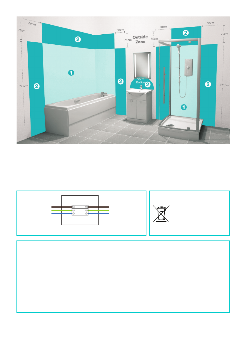
This product is suitable for installation in zones:
2 & Outside Zones
(Fig 1)
All installations must comply with guidelines which are based on a zonal concept. The diagram above
illustrates this concept and must be followed to ensure the safe installation of electrical appliances in the
bathroom. These regulations apply to domestic installations only. Installations must be made in accordance
with the current IEE wiring regulations and relevant building regulations. HiB recommends that all electrical
bathroom products should only be tted by a suitably qualied, Part P registered electrician.
Live is Brown
Earth is Green and Yellow
Neutral is Blue
earth
neutral
live
Live supply can be Red or Brown
Earth supply is Green and Yellow
Neutral supply can be Blue or Black
MAINS SUPPLYLUMINAIRE
WEEE compliance
Must not be mixed with
general household waste
Wiring Diagram (Fig 2)
Electrical Safety Information
HiB recommends that all electrical bathroom products should only be tted by a suitably qualied, Part P
registered electrician in accordance with current IEE regulations. Ensure mains power supply is switched
o before starting installation. Before drilling, ensure there are no hidden cables or pipes in the wall.
Care Instructions
Do not use abrasives or solvents when cleaning this product.
Wipe o all water spillages as soon as possible using a soft, damp cloth.
Aftercare Service
In the unlikely event that this product should fail please contact HiB customer services, contact detail
shown below.
T: +44 (0)20 8441 0352 F: +44 (0)20 8441 0219 E: [email protected] hib.co.uk
Building 3, North London Business Park, Oakleigh Road South, New Southgate, London. N11 1GN
©HiB Copyright: No part of this document may be reprinted or duplicated without HiB consent. All sizes and measurements are approximate, but we do try and
make sure they are as accurate as possible. In the interest of continuous product development, HiB reserves the right to alter specications as necessary. E & OE.
 Loading...