

Page 1
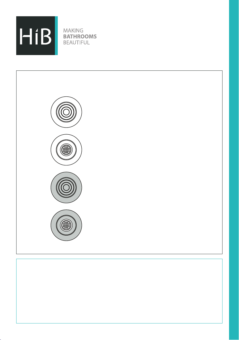
Cyclone Inline Fans
White - Non Illuminated
Art no.33300
White - Cool White LED
Art no.32600
White - Warm White LED
Art no.33800
Chrome - Non Illuminated
Art no.33400
Chrome - Cool White LED
Art no.32700
Chrome - Warm White LED
Art no.33700
Thank you for purchasing this HiB product.
Please read through these instructions carefully and refer back to them during installation to
ensure that your product is fitted safely and that it retains its high quality finish.
Please retain this leaflet for future reference.
Before drilling, ensure there are no hidden cables or pipes in the wall
Suitable for installation in zones:
Please see Fig. 1 on the back page for details
2 & Outside Zones
FI #05 001 R151221 Ver No. 1.0 Jan 2016
Page 2
In The Box
1. 1x Fascia
2. 1x LED Driver
(32600, 33800, 32700 & 33700 only)
3. 1x High powered Inline fan
4. 1x 3 metre flexible ducting (Ø100mm)
5. 1x Brown external fixed grille
6. 4x Galvanized steel hose clamps
7. 1x Screw and dowels pack
8. 1x Plastic screwdriver
9. 1x Fitting instructions
Warning
The Cyclone Illuminated Inline Fans (32600, 33800, 32700 & 33700) are supplied with an MR16
3 Watt LED lamp. This is the only lamp suitable for use with this fan. Do not replace with any other
lamp as this will invalidate any warranty. Do not exceed the stated wattage.
The fan must be connected to power mains through an automatic circuit breaker integrated into
the fixed wiring system with the gap between the breaker contacts on all poles not less than 3 mm.
Check the fan for any visible damages of the impeller and the casing before starting installation. The
casing internals must be free of any foreign objects which can damage the impeller blades. Misuse
of the product or any unauthorized modification is not allowed.
Take steps to prevent ingress of smoke, carbon monoxide and other combustion products into
the room through open chimney flues or other fire-protection devices. Sufficient air supply must
be provided for proper combustion and exhaust of gases through the chimney of fuel burning
equipment to prevent back draing.
Please Note; The fan may operate immediately when connected, this is normal
and due to a residual charge le in the capacitor during testing. Should this
occur, switch off, adjust timer to desired setting then turn back on. (see page 6
for Timer System)
2
Page 3
Mounting - Fascia
1. Ceiling mounted ventilation should be ducted through the roof space, by ducting to an external
soffit under the eaves or grille in the slope of your roof. NB: Ducting installed between a floor and
ceiling can only run between joists, not across them.
2. Mark the position of the vent fascia with a pencil in a suitable position on the ceiling, making sure
that it is between the joists.
3. Drill a 9mm hole through the ceiling anywhere along the edge of the pencil line. Now cut out the
hole with a pad saw.
4. Hold the vent fascia against the ceiling and mark the position of the fixing holes. Fix the unit in
place using suitable heavy duty plasterboard fixings (not supplied).
5. Attach flexible ducting with the metal hose clamps. Ensure that the ducting has a smooth
flow towards the motor body to minimise air resistance. Follow a similar procedure for the
outside wall grille. Extra ducting may be used to extend the distance to the external grille but
performance will be reduced.
Mounting - Fan unit
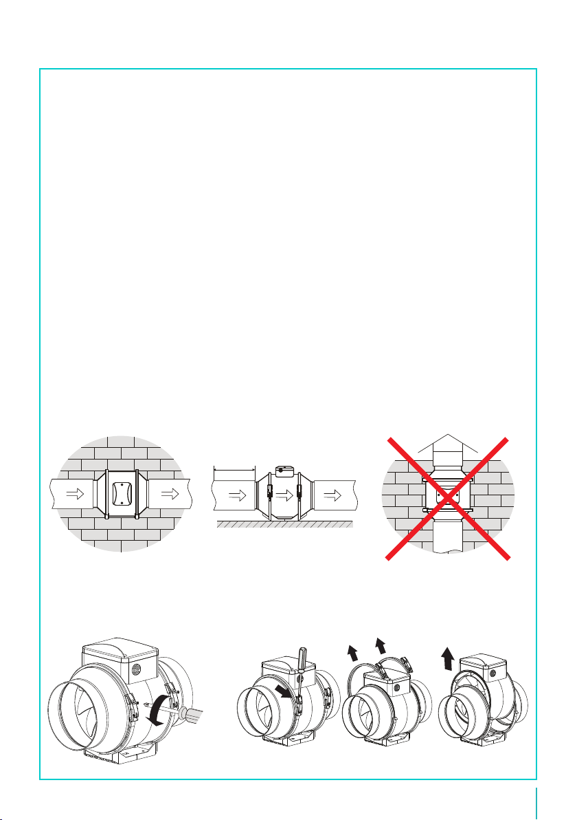
1. Install the Cyclone Inline fan within the lo or ceiling space (ensuring correct direction of air flow
using arrows on the fan). DO NOT COVER motor or LED driver with lo insulation. The fan is
suitable for only horizontal mounting on a wall (fig. A) or a floor (fig. B). When mounting the fan
ensure there is a minimum of 1m straight ducting to the motor body (see fig.B).
min 1m
g. A horizontal on a wall g. B horizontal on a oor Do not mount vertically
2. Using a screw driver, remove
3. Remove bracing clips & remove central unit.
screws on clips.
hib.co.uk
3
Page 4
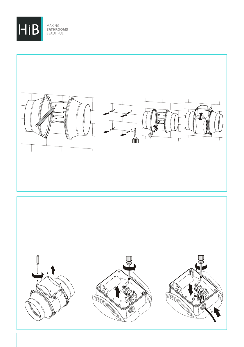
4. Place frame in desired
location and mark fixing
holes.
6. Connect the flexible ducting to both sides of the Inline fan with the metal hose clamps. Ensure
there is a minimum of 1m straight ducting between fascia and fan.
5. Fix frame to desired surface, using fixings suitable for
wall type. Then replace central unit and bracing clips.
Electrical Connection
Ensure the mains power supply to which the fan is being connected is turned off. This product is
designed to be connected to an on/off switch outside the bathroom, or to a ceiling mounted pull
cord switch.
1. Using a screw driver,
remove cover.
4
2. Using a screw driver,
remove cable grip.
3. Feed cable through hole
& replace grip.
Page 5
4. Wire the fan as per fig. C below.
Neutral
QF
N
~
N
L
L
ST
QF - Circult Breaker
ST - External Switch (e.g. light switch)
5. Amend the timer setting, if desired, following the process on page 6. Replace cover using a
suitable screw driver.
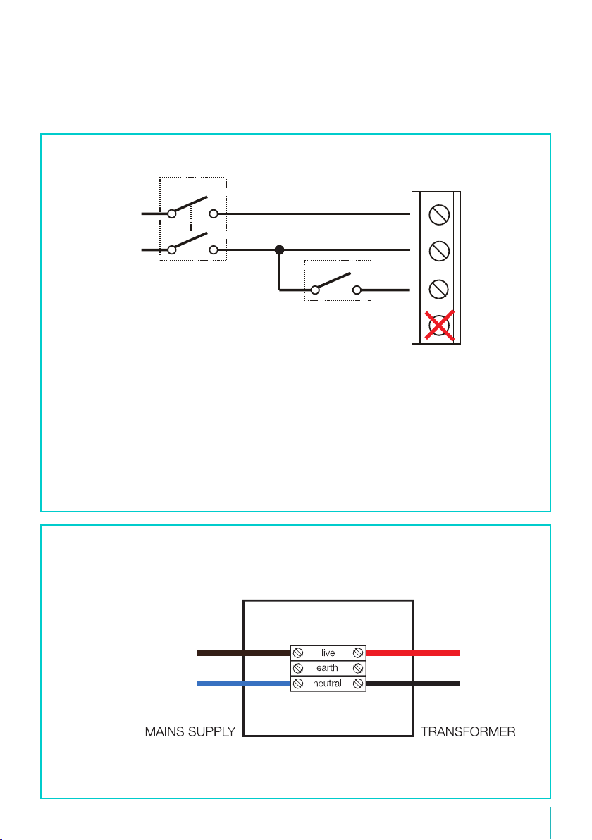
6. On Illuminated versions (32600, 33800, 32700 & 33700) the mains supply should be connected
to the LED driver as per the wiring diagram for lamp (Fig. D).
7. Fix the external grille to the soffit in the same way as the ceiling fascia with 4 screws.
8. For illuminated Cyclone vents, follow the wiring diagram below (Fig. D).
LT
LIDo Not Use
(Fig. C)
Wiring Diagram For Lamp
(32600, 33800, 32700 & 33700 only)
supply is Blue or Black
AC in DC out
Live is RedLive supply is Red or Brown
Neutral is Black
(Fig. D)
hib.co.uk
5
Page 6
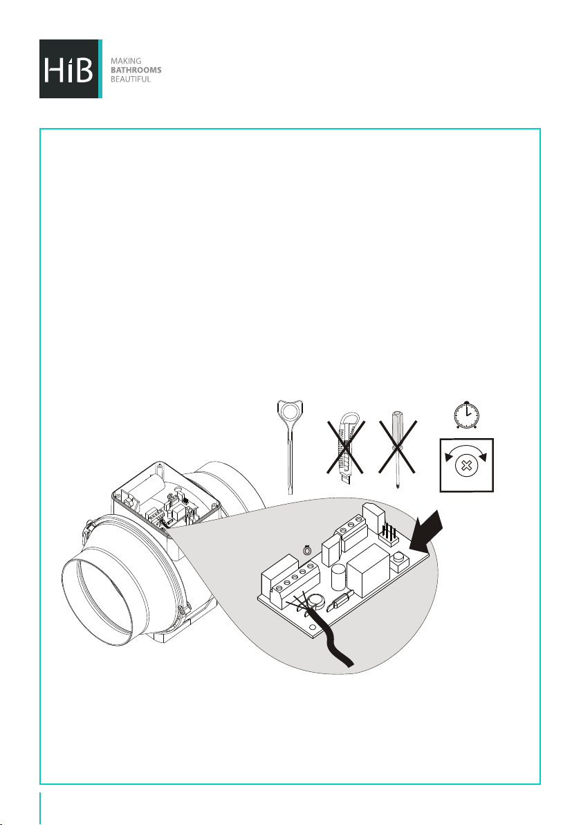
Timer System
Warning! The timer circuit is under mains voltage. Ensure mains power supply is switched off
before making any adjustments.
The fan is operational aer the control voltage is supplied by the external switch (e.g., by the light
switch) to the input terminal LT. Aer the fan is switched off the fan continues to operate within the
timer period set by the timer from 2 to 30 minutes. To adjust the run on timer, rotate the control knob
clockwise to increase and anti-clockwise to decrease the off-delay time respectively (see below
diagram). Please note the adjustment should only be done without the fan running.
The set includes a specially designed plastic screwdriver for timer setting adjustments. Only use the
plastic screwdriver to alter the turn-off delay time. Do not use a screwdriver, knife, etc. for adjustments
so as not to damage the circuit board.
-
+
2 min
Õ
30 min
6
Page 7

Operation
The fan is rated for connection to single-phase AC220-240 V / 50/60 Hz power mains. The fan is
designed for continuous operation always connected to mains power. Air motion direction in the
system must match the pointer on the fan casing. Ingress protection rating IPX4.
Maintenance
Fan maintenance is to be performed only aer the fan is disconnected from the mains power suppy.
Maintenance means periodic cleaning of the surface of dust and dirt.
All surfaces should be cleaned with diluted detergent, i.e. washing up liquid, and a so cloth.
Scourers and scouring agents should not be used, as these may cause damage to the surface of the
product.
Avoid water dripping on the electric components. Wipe the surfaces dry aer cleaning.
Technical Information
Power Input: 220-240V, 50/60Hz
Maximum Ventilation Volume: 210 m3/hr (±5%) / 58.333 Litres Per Second
Power Consumption: 25W + 3W LED Lamp (32600, 33800, 32700 & 33700 only)
Decibel: 32dB
Dimensions: Ø14 x D7.3cm
hib.co.uk
7
Page 8
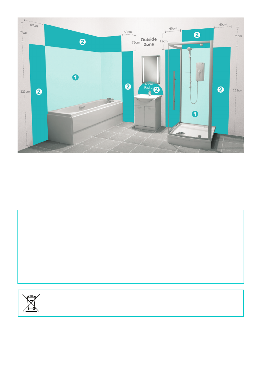
(Fig 1)
These products are suitable for installation in zones:
All installations must comply with guidelines which are based on a zonal concept. The diagram above
illustrates this concept and must be followed to ensure the safe installation of electrical appliances in
the bathroom. These regulations apply to domestic installations only. Installations must be made in
accordance with the current IEE wiring regulations and relevant building regulations. HiB recommends
that all electrical bathroom products should only be fitted by a suitably qualified, Part P registered
electrician.
2 & Outside Zones
Electrical Safety Information
Ensure mains power supply is switched off before starting installation. Before drilling, ensure there are
no hidden cables or pipes in the wall.
Care Instructions
Do not use abrasives or solvents when cleaning this product.
Wipe off all water spillages as soon as possible using a so, damp cloth.
Aercare Service
In the unlikely event that this product should fail please contact HiB customer services, details shown
below.
WEEE compliance
Must not be mixed with general household waste
T: +44 (0)20 8441 0352 F: +44 (0)20 8441 0219 E: [email protected] hib.co.uk
Building 3, North London Business Park, Oakleigh Road South, New Southgate, London. N11 1GN
©HiB Copyright: No part of this document may be reprinted or duplicated without HiB consent. All sizes and measurements are approximate, but we do try and
make sure they are as accurate as possible. In the interest of continuous product development, HiB reserves the right to alter specifications as necessary. E & OE.
 Loading...