

H&H Specialties 700 Installation Instructions

700 SERIES LIGHT-DUTY
CURVED TRACK
INSTALLATION INSTRUCTIONS
PLEASE READ INSTRUCTIONS THOROUGHLY
BEFORE BEGINNING.
The 700 Series Track is a light-duty I-beam style suitable for
curved or straight curtains up to 40 feet. This Series is for walkalong use only and cannot be rigged for cord operation. A 4'-0"
minimum is suggested for ease of operation and for optimum
life.
A. GENERAL INSTRUCTIONS
1. Before raising track into position, determine location of
hangers. Install end stop (709) at one end of the track.
2. Place track either on the floor or on sawhorses in the
configuration of the finished track. If track needs to be spliced,
please refer to the section on splices in "Special Instructions."
3. Install hangers (706 or 711) evenly along the entire run of the
track starting adjacent to the end. Refer to recommended
spacing provided. Additional hangers should be installed on
curves and others may be required due to site conditions.
4. The 700 Series may also be suspended with wire rope or
welded link chain. Use attachment method appropriate to
application and as determined by a qualified person.
5. For COMPLETE Tracks, one single carrier (701, 716, or
728) is provided per foot of track and one pair of master carriers
(702, 717, or 729) are provided, one for each end of curtain.
Install single and master carriers on track. Finally, install one
end stop (709) on open end of track to captivate single and
master carriers.
sections of track. If track must be spliced on a curve it is
necessary to interrupt the radius in that location with a short
straight section of track (4" minimum) to accommodate the
splice.
3. A drill fixture (707FX) is available from the factory to
facilitate field drilling of splices for the 700 Series track.
Pivot Devices: Pivot devices are not available from the factory
and are not to be used with the 700 Series Track. .
RECOMMENDED TRACK SUPPORT SPACING
Curtain Weight
Per Carrier (pounds)
The user is cautioned that H & H Specialties Inc. cannot guarantee the
accuracy of the data presented in this table for every situation. It is the
customer’s responsibility to determine the suitability of H & H
Specialties’ products for any given application, taking into account the
specific requirements, the environment of use, and any possible
peculiarities of the application.
Using 706 Clamp Hanger or
711 Ceiling Hanger (in feet)
706 Hanger 711 Ceiling
Clamp
244
334
433.5
6. The curtain may now be attached to the carriers.
B. CEILING MOUNT INSTALLATION
1. After laying out the track, use a plumb line or laser to locate
positions of the ceiling hangers relative to the track. Use
appropriate attachment methods for the individual job
conditions. Before installing ceiling hangers (711) make sure
that the ceiling is parallel to the floor. Shims may need to be
installed to compensate for irregularities.
2. After the hangers are installed, raise the track in sections and
attach to the ceiling hangers. In many cases, ceiling hangers can
be installed onto the track, then raised to the ceiling for
mounting of the hanger.
3. Install single and master carriers per the above.
C. MISCELLANEOUS
Splices:
1. In order to have a smooth operating track it is important that
the track splices are installed properly and carefully. Make sure
that the ends of the track are smooth and no ragged edges are
protruding.
2. Whenever possible, splices should be located on straight
DISCLAIMER
This product is designed for moving curtains or, in
some cases, scenery.
NONE OF THE ITEMS DESCRIBED HEREIN ARE
DESIGNED, INTENDED OR WARRANTED FOR
THE USE OF LIFTING OR TRANSPORTING
PEOPLE OR OTHER LIVING OBJECTS.
H & H Specialties Inc. makes no representation of the
suitability of any product for any application unless
specific design drawings are made by the factory and
the products are installed in precisely the manner
detailed by our design staff.
H & H Specialties Inc. 700 Series Installation
South El Monte, CA 91733 December 08, 2007
Page 1 of 1
&
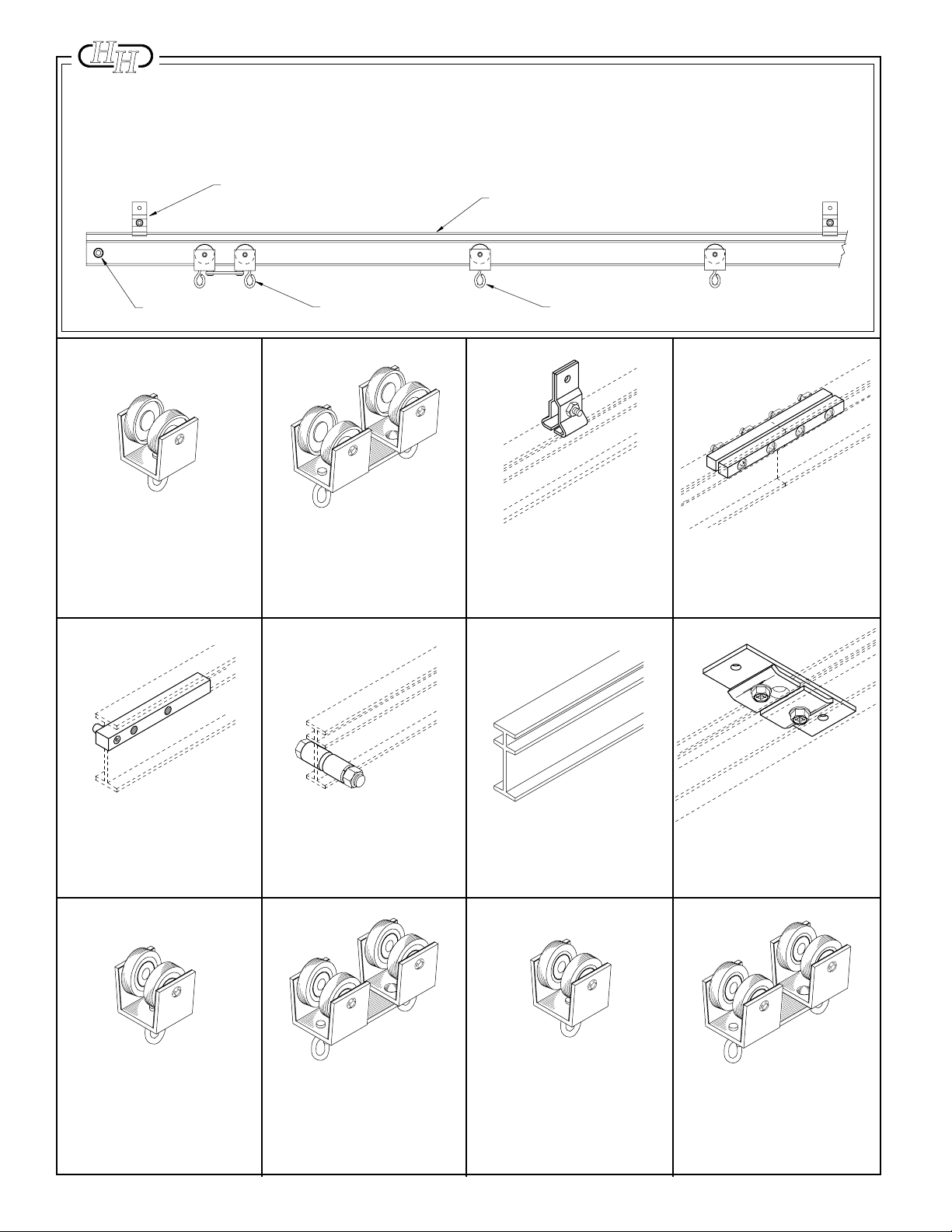
700 SERIES LIGHT-DUTY CURVED TRACK
706 CLAMP HANGER
710 TRACK
COMPLETE TRACK
MODEL NUMBERS
701A
716A
728A
709 END STOP
No. 701 SINGLE CARRIER
2 Delrin wheels riveted to extruded aluminum
body with swivel hook. Nylatron glide strips
reduce friction and noise.
702 MASTER CARRIER
No. 702 MASTER CARRIER
2 Delrin wheel assemblies with swivel pivot
on steel connecting plate. 1 pair recommended for each walk-along curtain.
701 SINGLE CARRIER
No. 706 CLAMP HANGER
Formed steel brackets clamp to track.
Adjusts to any position. Suspend track with
welded chain or wire rope.1 pair pictured.
Steel plates align and lock track together. 1
No. 707 SPLICE
pair pictured.
No. 707FX SPLICE
DRILL FIXTURE
Hardened tool steel drill fixture for field drilling
of track for 707 splices.
No. 716 SINGLE CARRIER
Nylon-tired shielded ball bearing wheels
riveted to extruded aluminum body with
swivel hook. Nylatron glide strips reduce
friction and noise.
36
Bolt with steel spacers to prevent carriers
No. 709 END STOP
from traveling beyond desired location. 1 pair
required for each track.
No. 717 MASTER CARRIER
2 nylon-tired shielded ball bearing wheel
assemblies with swivel pivot on steel connecting plate. 1 pair recommended for each
walk-along curtain.
Mill finish 6063-T5 extruded aluminum
No. 710 TRACK
5/8" wide x 1-11/16" high, .094" thick. 20'
stock length.
No. 728 SINGLE CARRIER
Neoprene-tired shielded ball bearing wheels
riveted to extruded aluminum body with
swivel hook. Nylatron glide strips reduce
friction and noise.
No. 711 CEILING HANGER
Steel plate mounts flush to ceiling. Track
clamps to bracket with offset clips.
No. 729 MASTER CARRIER
2 neoprene-tired shielded ball bearing wheel
assemblies with swivel pivot on steel connecting plate. 1 pair recommended for each
walk-along curtain.
 Loading...