

H&H Specialties 300 Installation Instructions

300 SERIES STANDARD DUTY
STRAIGHT TRACK
INSTALLATION INSTRUCTIONS
PLEASE READ INSTRUCTIONS THOROUGHLY
BEFORE BEGINNING.
A. BI-PARTING TRAVEL
1. Before raising track into position, determine location of
spindles, idlers, and other accessories and drill appropriate
holes. If conditions allow, all spindles, idlers, and end pulleys
may be installed. See “special instructions” for information on
placement and number of spindles suggested. Do not place end
stops in the center of the track at this time.
2. Place track either on the floor or on sawhorses in the
configuration of the finished track. When laying out the track,
make sure that the track which has the double end pulley (303)
is outside the curve of the single end pulley (304) track. Make
sure the tracks are overlapped the proper amount, 2'-0" is
considered standard. If track needs to be spliced, please refer to
the section on splices in "Special Instructions."
3. Attach track at overlap with 1 set (two 305) overlap clamps
approximately 6" from each end. Install hangers (306) evenly
along the entire run of the track starting adjacent to end pulleys.
Refer to recommended spacing provided. Additional hangers
should be installed on curves and others may be required due to
site conditions.
4. If a batten is used to stiffen the track, place the pipe clamp
(435) loosely on the batten. Raise the track and attach to the
pipe clamps. The 300 Series may also be suspended with wire
rope or welded link chain. Use attachment method appropriate
to application. The track has been punched at the factory for
splices, however, make sure that the track is free from burrs or
proper alignment of the track sections may not be possible.
5. Attach the double end and single end pulleys to their
respective tracks if not previously done. CAUTION! Make
sure that end pulleys are solidly anchored to the track.
9. Reeve the operating line through the single end pulley and
around the outside idlers (320). Next, the operating line passes
through the end stop & cord support on the double end pulley
track and terminates at the rope clamp of the master carrier on
the double end pulley track. The other end of the line runs
through the tension floor block (308) and back toward the
double end pulley. NOTE: The spring in the tension floor
block should be extended when the operating line is first reeved.
10. Reeve the operating line over the bottom sheave of the
double end pulley, around bottom roller of double spindle (318),
and terminate at the master carrier. NOTE: Both free ends are
now located at this master carrier. Make sure that there is
sufficient operating line remaining to reach the intended
finished height. At this time, make sure that all end stops are
secured in place. Release spring in tension floor block to place
operating line under tension. CAUTION! Exercise care when
releasing tension in spring to avoid injury. For counterweight
batten mounted tracks a 643 Sand Bag Tension Pulley should be
used.
11. Slide each to the master carriers to the center stops and
tighten all of the rope clamps. Move the operating line to make
sure that the track operates smoothly and track does not flex at
any time. If problems exist, correct now prior to hanging
curtain.
12. The curtain may now be attached to the carriers.
WARNING! After attaching the curtain to tracks mounted
on a counterweighted batten, the line set must be balanced.
Always use caution when working with an out-of-balance
line set.
B. ONE-WAY TRAVEL
6. From the center of the track, install single carriers (301, 316,
or 328) into each side (1 single carrier per foot of track). Next,
install one master carrier (302, 317, or 329) into each track.
Finally, install one end stop & cord support (309) on each end
of the track.
7. IMPORTANT! Make sure track is parallel to floor before
final attachment. WARNING! After attaching track to a
counterweighted batten, make sure to balance the line set
and leave at a comfortable working level.
8. Start to reeve the operating line from the upper sheave of the
double end pulley. The rope goes over the sheave and through
the top sheave of the double spindles (318) toward the center
overlap and through the end stop & cord support. Next, the line
passes through the master carrier on the single end pulley side
track and around the single spindles (319). Do not tighten
master carrier cord clamps at this time.
1. Before raising the track, all spindles and other accessories
should be placed and all necessary holes drilled. If conditions
allow, spindles can be installed. See "Special Instructions" for
information on placement and number of spindles required.
2. Lay the track sections on the floor or on sawhorses in the
configuration of the finished track.
3. Install hangers (306) evenly along the entire run of the track
starting adjacent to end pulleys. Refer to recommended spacing
provided. Additional hangers should be installed on curves and
others may be required due to site conditions.
4. If a batten is used to stiffen the track, place the pipe clamp
(435) loosely on the batten. Raise the track and attach to the
pipe clamps. The 300 Series may also be suspended with wire
rope or welded link chain. Use attachment method appropriate
to application. The track has been punched at the factory for
splices, however, make sure that the track is free from burrs or
H & H Specialties Inc. 300 Series Installation
South El Monte, CA 91733 February 20, 2007
Page 1 of 3
proper alignment of the track sections may not be possible.
5. Attach the double end pulley (303)to one end of the track.
From the other end insert single carriers (301, 316, or 328) and
the insert the master carrier (302, 317, or 329) into the track.
Finish by attaching the single end pulley (304A). NOTE: For
one-way operation a 304A single end pulley should always be
used.
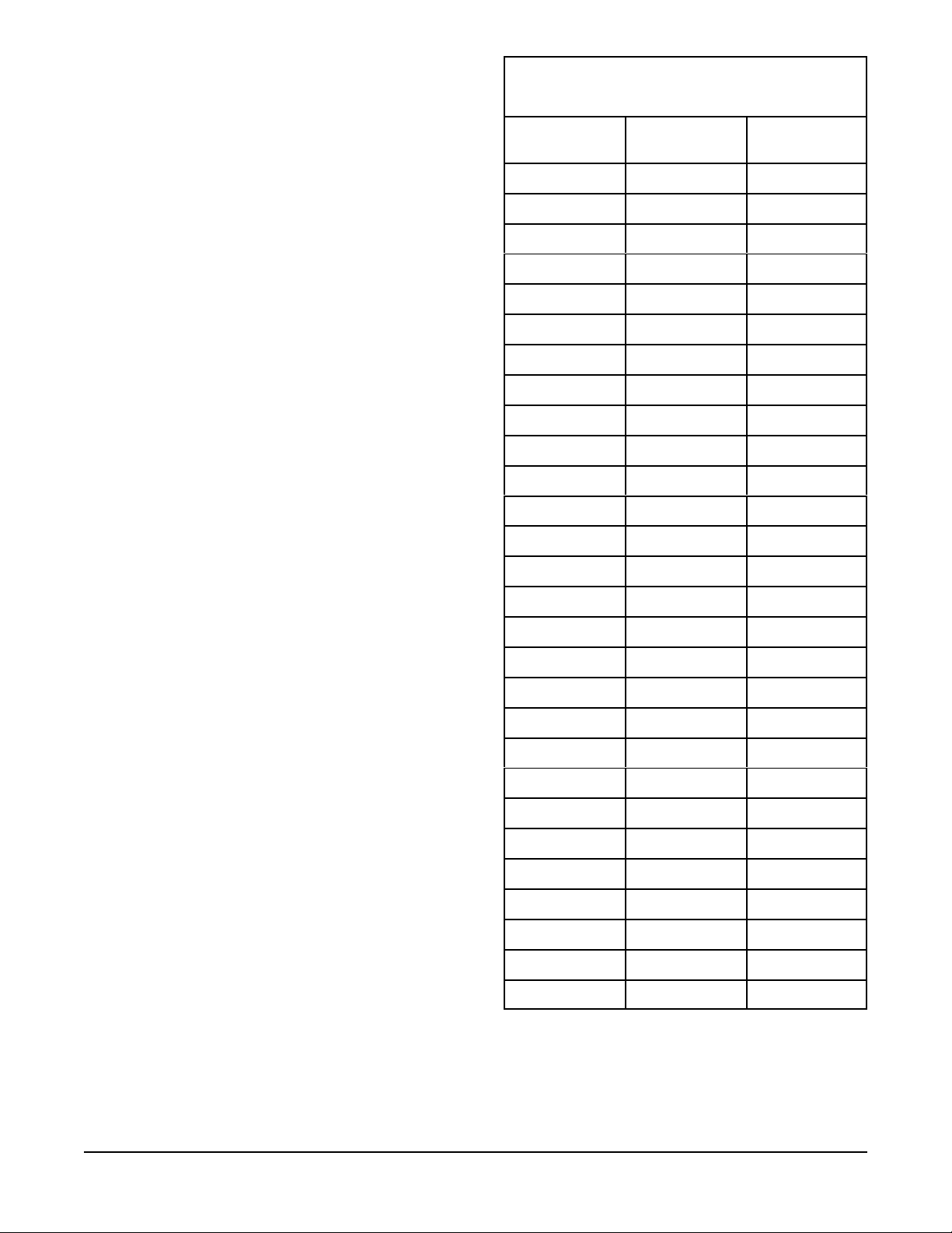
RECOMMENDED SPINDLE & IDLER SPACING FOR
CURVED 300 SERIES TRACKS
(based upon 90 degree curve)*
Radius Spindle/Idler
Spacing
Suggested
Quantity
2'-0" consult factory consult factory
6. If the track is being suspended from a counterweight system,
balance the system now. WARNING! After attaching track
to a counterweighted batten, make sure to balance the line
set and leave at a comfortable working level.
7. Start to reeve the hand line from the upper sheave of the
double end pulley. The rope goes over the sheave and through
the top sheave of the double spindles (318). In one-way track
installations, the double spindle is the only spindle used.
8. Reeve the hand line around the sheave of the single end
pulley and back to the master carrier. Terminate the hand line
into the rope clamp of the master carrier..
9. Reeve the other end of the hand line through the tension
spring floor block and up to the double end pulley. The spring
in the tension block should be extended when operating line is
first reeved. Reeve the handline over the sheave and terminate
at the master carrier. Remove slack in line and tighten cord
clamps. Release spring in floor block to place line under
tension. CAUTION! Exercise care when releasing tension in
spring to avoid injury. For counterweight batten mounted
tracks a 643 Sand Bag Tension Pulley should be used.
C. CEILING MOUNT INSTALLATION
Ceiling mounting the 300 Series is similar to the batten
mounting procedures. The following considerations should be
followed when ceiling mounting.
3'-0" consult factory consult factory
4'-0" 15" 6
5'-0" 16" 7
6'-0" 20" 7
7'-0" 22" 7
8'-0" 25" 7
10'-0" 32" 7
12'-0" 38" 7
14'-0" 38" 8
16'-0" 42" 8
18'-0" 48" 8
20'-0" 52" 8
22'-0" 60" 8
24'-0" 57" 9
26'-0" 61" 9
28'-0" 66" 9
30'-0" 71" 9
1. After laying out the track, use a plumb line or laser to locate
positions of the ceiling hangers relative to the track. Use
appropriate attachment methods for the individual job
conditions. Before installing ceiling hangers (311) make sure
that the ceiling is parallel to the floor. Shims may need to be
installed to compensate for irregularities.
2. After the hangers are installed, raise the track in sections and
attach to the ceiling hangers. In many cases, ceiling hangers can
be installed onto the track, then raised to the ceiling for
mounting of the hanger.
3. Rig track for either bi-parting or one-way travel.
D. SPECIAL INSTRUCTIONS
Spindles
1. For 300 Series tracks a radius of 4'-0" is recommended for
ease of operation. Tighter curves are possible and will result in
a system that requires additional effort to operate. For these
applications, consult the factory.
32'-0" 75" 9
36'-0" 75" 10
40'-0" 75" 11
44'-0" 75" 12
48'-0" 75" 12
52'-0" 75" 14
56'-0" 75" 15
60'-0" 76" 16
64'-0" 76" 17
68'-0" 76" 18
*For manual cord-operated tracks with a radius of 8'-0" or less,
the addition of one spindle and idler will help ease of operation
2. In locating spindles, place so that the cord is adequately
supported as it turns the corner. Use the following chart for
reference only. Due to site conditions, the numbers of spindles
required for ease of operation may vary.
H & H Specialties Inc. 300 Series Installation
South El Monte, CA 91733 February 20, 2007
Page 2 of 3
3. Double spindles (318) are mounted on the inside of the curve
on the double end pulley track only.
4. Single spindles (319) are mounted on the inside of the curve
on the single end pulley track only.
5. Outside idlers (320) are mounted on the outside of the curve
on the single end pulley track only.
6. Spindles and idlers are also suggested on straight track
sections of 6'-0" and longer.
3. When using the curved 300 Series track with light-weight
fabrics, the carriers may bind as they go around the curve.
Adding weight to the bottom of the curtain and connecting the
carriers together with chain will help alleviate the problem.
4. NOTE: Rigged 300 Series tracks (manual and machine
operated) are not designed for reverse or "S" curve operation.
The design and operation of the spindle and idler assemblies
does not allow this feature. If design of track layout requires a
reverse bend, the 500 Series heavy duty curved track is a
suitable choice. 300 Series tracks may be reverse curved for
walk-along applications only.
7. Since idler number, spacing and placement are unique for
each job, please consult the factory for further information.
Splices
1. In order to have a smooth operating track it is important that
the track splices are installed properly and carefully. Make sure
that the ends of the track are smooth and no ragged edges are
protruding.
2. Whenever possible, splices should be located on straight
sections of track. If track must be spliced on a curve it might be
necessary to bend the splice to match the radius of the bend.
3. A drill fixture (307FX) is available from the factory to
facilitate field drilling of splices for the 300 Series track.
Pivot Devices
1. Pivot devices allow for curtains to be positioned at different
angles relative to the track. Both the 30 and 30X are freewheeling devices. The 30BK brake kit is available as an
optional accessory for holding the device in a fixed position.
The "X" suffix stands for a special indexing device that allows
the curtain to be placed in preset positions at 22½
o
increments.
2. The pivot device is designed for either 1-3/8"O.D. tubing or
1" Sch. 40 pipe. Maximum recommended batten length is 6'-0".
Make sure that the batten is the proper length for the
application.
3. Place the "C" clamps in each end of the curtain batten. They
are provided so that a cord may be tied between the two to aid in
turning the device. The cord should be long enough so that
adjustment may be done with the curtain at its proper trim.
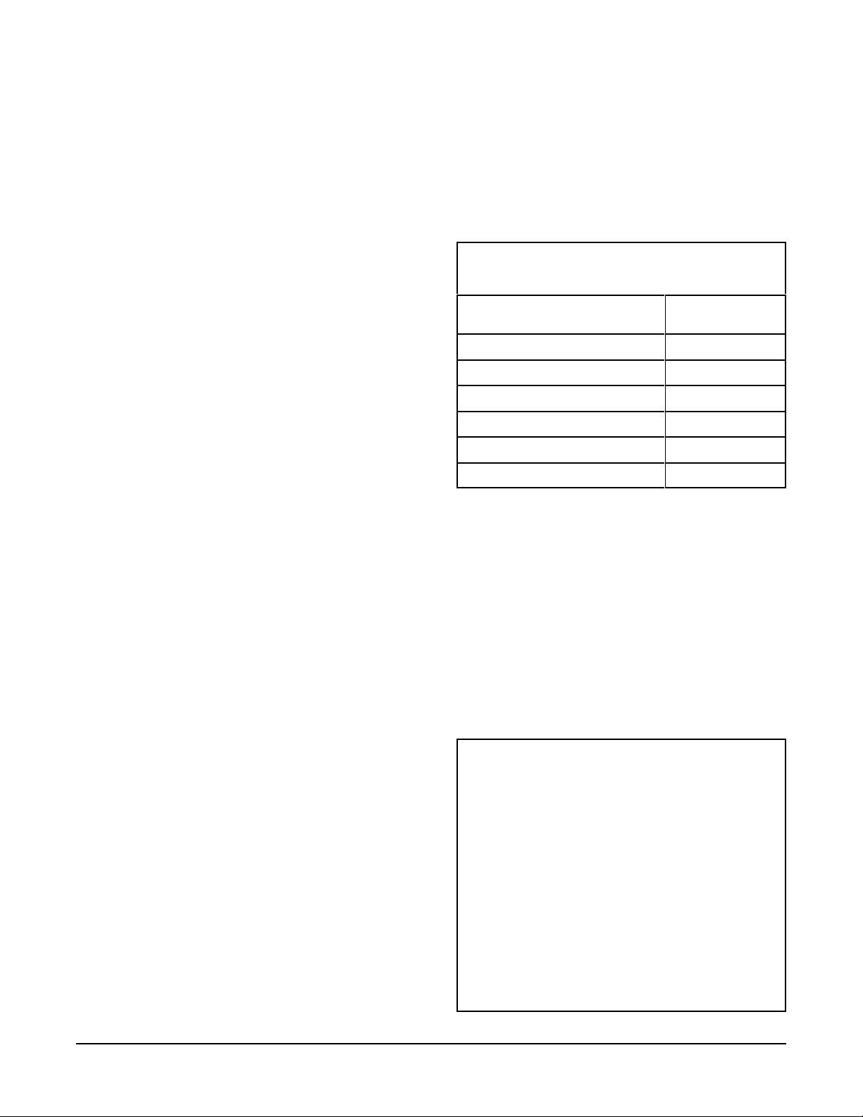
RECOMMENDED TRACK SUPPORT SPACING
Per Carrier (pounds)
For additional information, please refer to Catalog Fourteen, pages 62-
63. For tracks 10 feet or less in length it is recommended that the track
be supported at a minimum of three locations.
All recommendations stated are presented in good faith and based upon
generally accepted engineering principles. The user, however, is
cautioned that H & H Specialties Inc. cannot guarantee the accuracy of
the data presented in this table for every situation. It is the customer’s
responsibility to determine the suitability of H & H Specialties’ products
for any given application, taking into account the specific requirements,
the environment of use, and any possible peculiarities of the application.
for this application.
Direct ceiling attachment of tracks has not been evaluated as the support
structure, method of attachment, and attachm e nt requirements may vary
widely from project to project. A qualified person should be consulted
Using 306 Clamp Hanger or
311 Ceiling Hanger (in feet)
Curtain Weight
25
35
45
54.5
64
74
310A
DISCLAIMER
4. CAUTION! Do not attempt to adjust the curtain by
means of pulling on the fabric. Damage to the curtain and
This product is designed for moving curtains or, in
some cases, scenery.
associated hardware may result.
NONE OF THE ITEMS DESCRIBED HEREIN ARE
5. The recommended total load on the device
75 pounds.
Miscellaneous
1. Rubber bumpers are supplied (2 for each carrier) and should
be placed on the "ears" on the side of the carrier that face the
end pulleys.
must not exceed
DESIGNED, INTENDED OR WARRANTED FOR
THE USE OF LIFTING OR TRANSPORTING
PEOPLE OR OTHER LIVING OBJECTS.
H & H Specialties Inc. makes no representation of the
suitability of any product for any application unless
specific design drawings are made by the factory and
the products are installed in precisely the manner
2. A 4'-0" minimum is suggested for ease of operation and for
optimum life. Consult the factory for a radius less than 4'-0".
detailed by our design staff.
H & H Specialties Inc. 300 Series Installation
South El Monte, CA 91733 February 20, 2007
Page 3 of 3
 Loading...