


100 SERIES STANDARD DUTY
STRAIGHT TRACK
INSTALLATION INSTRUCTIONS
PLEASE READ INSTRUCTIONS THOROUGHLY
BEFORE BEGINNING.
A. BI-PARTING TRAVEL
BATTEN INSTALLATION
1. Place track either on the floor or on sawhorses under the
batten to which it will be attached. Make sure the tracks are
overlapped the proper amount, 2'-0" is considered standard.
Stage left track is always
spliced, please refer to the section on splices in "Special
Instructions."
2. Attach track at overlap with 1 set (two 105) overlap clamps
approximately 6" from each end. Install hangers (106) evenly
along the entire run of the track starting adjacent to end pulleys.
Refer to recommended spacing provided. Additional hangers
may be required due to site conditions. If the track is on the
floor, installer may wish to attach the track to the batten and
raise to a comfortable working level. Refer to step 5 for
attachment instructions.
3. Attach end stops (109) to the onstage (center) ends of the
track. From the offstage ends of the track, install one master
carrier (102 or117) into each track. Next, install single carriers
(101 or 116) into each track behind the master (1 single carrier
per foot of track).
4. Decide from which end the curtain will be operated. This is
the side that the double end pulley (103) will be attached.
Attach pulley to end of track with chain bracket off to the side.
After attaching the double end pulley, go to the opposite side of
the track and install the single end pulley (104). Make sure that
end pulleys are installed in a manner similar to that indicated on
the plan view detail in attached drawings.
5. Attach the track to the batten with either wire rope, welded
link chain, or pipe clamps. Use attachment method appropriate
to application. When using pipe clamps, a center pipe support
(126) should be used to eliminate twisting through the overlap.
IMPORTANT! Make sure track is parallel to floor before final
attachment. WARNING! After attaching track to batten,
make sure to balance the line set and leave at a comfortable
working level.
6. Attaching a rope clamp to one end of operating line, reeve
the OTHER end of line through the master carrier, single
carriers, and through center sheave of double end pulley. When
using 116 carriers make sure that a rubber bumper is installed
between each carrier when reeving operating line.
7. Reeve line through the floor block (108) or the sand bag
tension pulley (643) and back over the other sheave of the
double end pulley.
8. Next, the line travels toward the single end pulley. Reeve
the line through the end stop & cord support, master carrier,
single carriers, and around the single end pulley. Make sure to
placed downstage. If track needs to be
put rope clamps on the operating line when going through the
master carrier. CAUTION! Do not tighten at this time. The
line travels through the other end stop & cord support and
terminates where it started at the first master carrier. Place the
line through the master and attach the rope clamp to the
operating line leaving a small tail.
9. Make sure that all the slack in the line is on the double end
pulley side (side with the floor block). Also make sure that
there is sufficient line remaining to reach the intended finished
height.
10. Slide each of the master carriers to the onstage (center) end
stops. Now tighten each of the clamps on each master carrier.
Raise the track to its desired height. Check to see that the floor
block or sand bag tension pulley is taking the slack out of the
operating line. Operate the track to make sure everything is
running smoothly. If not, go through the entire system and
check to make sure the components are installed properly.
11. The curtain may now be attached to the carriers.
WARNING! After attaching the curtain, the line set must
be balanced. Always use caution when working with an outof-balance line set.
12. Raise the curtain and track to the desired height and adjust
the floor tension block until the operating line has no slack in it.
If a sand bag tension pulley is used, make sure the bag is filled
with dry sand (not provided with sand bag) and the bag is
securely attached to the steel housing.
B. ONE-WAY TRAVEL
BATTEN INSTALLATION
1. Place the track either on the floor or on sawhorses under the
batten to which it will be attached. If track needs to be spliced,
refer to the section on splices in "Special Instructions."
2. Install hangers (106) evenly along the entire run of the track
starting adjacent to end pulleys. Refer to recommended spacing
provided. Additional hangers may be required due to site
conditions. If the track is on the floor, installer may wish to
attach the track to the batten and raise to a comfortable working
level. Refer to step 5 for attachment instructions.
3. Decide from which end the curtain will be operated. This is
the side that the double end pulley (103) will be attached. Do
not attach the pulley to the end of the track at this time. Attach
to the opposite side of the track the single end pulley (104).
Make sure that both end pulleys will be mounted in such a
manner that both of the sheaves are on the same side of the
track. The upstage side is preferred for cosmetic reasons.
4. From the double end pulley side of the track, install a master
carrier (102 or 117) into track. Next, install single carriers (101
H & H Specialties Inc. 100 Series Installation
South El Monte, CA 91733 February 20, 2007
Page 1 of 3

or 116) into track behind the master (1 single carrier per foot of
track). Finally, attach the double end pulley on the track.
5. Attach the track to the batten with either wire rope, welded
link chain, or pipe clamps. Use method appropriate to
application. IMPORTANT! Make sure track is parallel to the
floor before final attachment. WARNING! After attaching
track to batten, make sure to balance the line set and leave
at a comfortable working level.
6. Attach a rope clamp to one end of operating line. Reeve the
OTHER end of the line through the master carrier, single
carriers, and through the center sheave of double end pulley.
When using 116 carriers, make sure that a rubber bumper is
installed between each carrier when reeving operating line.
7. Reeve line through the floor block (108) or the sand
bag tension pulley (643) and back over the other sheave of the
double end pulley.
8. Next, the line now travels to the single end pulley. Reeve
around the single end pulley and back to the master carrier.
Place the line through the master carrier and attach the rope
clamp to the operating line leaving a small tail.
9. Raise the track to the desired height. Check to see that the
floor block or sand bag tension pulley is taking the slack out of
the operating line. Operate the track to make sure everything is
running smoothly. If not, go through the entire system and
check to make sure the components are installed properly.
10. The curtain may now be attached to the carriers.
WARNING! After attaching the curtain, the line set must
be balanced. Always use caution when working with an outof-balance line set.
splice.
4. On either a dead hung or ceiling installation using Model
101S or 101A, it is recommended that trim chains (135) be
installed on the carriers to provide adjustment in curtain height.
Dead Hung Installation
1. Determine where the hanging points for the track will be.
Use either wire rope or welded link chain to hang track.
Hanging points need to be at ends adjacent to end pulleys and
evenly spaced along the entire run of the track. Refer to
recommended spacing provided. Additional hangers may be
required due to site conditions. Hanging method must be
adjustable to allow for trimming the track parallel to floor.
2. Place track on the floor or on sawhorses in the exact location
that the track will be positioned. If the track is overlapped,
allow 2'-0" for this purpose. Place track hangers on track under
hanging points.
3. Raise track in sections and attach to hanging points.
Leveling the track in sections is suggested. If the track is
overlapped, remember to attach the overlap clamps after both
tracks are correctly positioned. Depending on curtain material,
the track may need to be hung 1-3 inches higher than its finished
height to allow for fabric stretch. After the curtain has been
hung for a period of time, it may need to be re-trimmed.
4. Once the track has been hung and leveled, the track is rigged
the same as a batten mounted track for either one-way or biparting (Steps 3,4 & 6-12).
Ceiling mount
11. Raise the curtain and track to the desired height and adjust
the floor tension block until the operating line has no slack in it.
If a sand bag tension pulley is used, make sure the bag is filled
with dry sand (not provided with sand bag) and the bag is
securely attached to the steel housing.
C. DEAD HUNG OR CEILING MOUNT
INSTALLATION
Before Beginning.
1. When installing a dead hung track, a decision must be made
whether to install the track in sections or as a complete unit.
Basis for this decision is the ability of the installer to lift and
hold the track in place. The 110S track channel weighs 1.50
pounds per foot. (30 pounds for a 20'-0" length).
2. If installing on a ceiling, make careful measurements to
determine if the ceiling is parallel to the floor. If not, shim the
track accordingly. Also, take careful measurements in
determining structural points in the ceiling to attach the track.
Use appropriate hardware to attach the track to the ceiling based
on roof structure and total track loads.
3. If track needs to be spliced with ceiling splice (127), splicing
is sometimes easier if done on the floor or on sawhorses. The
ceiling splice is a bolt through splice and care is needed to
assure that the carriers will still pass through the splice.
CAUTION! Wheels of 10 pivot device will not pass a 127
1. After determining the condition of the ceiling and its relation
to the floor, lay the track on the floor or on sawhorses in the
position that it will be installed. Using a plumb line, mark and
drill for attachment to ceiling under each structural support to
which it will be attached.
2. Use a plumb line to determining the position of the track
relative to the ceiling. Raise the track and use appropriate
hanging method for job conditions. Make sure the track is
parallel to the floor and provisions have been made to trim for
curtain stretch.
3. After the track is installed, it is rigged in the same way as a
batten mounted bi-parting or one-way track. (Steps 3,4 & 6-12).
Note: Clamp hangers and overlap clamps are not provided or
used with ceiling mounted COMPLETE tracks.
D. SPECIAL INSTRUCTIONS
Splicing Track
1. In order to have a smooth operating track it is important that
the track splices are installed properly and carefully. Do not
over tighten the fasteners.
2. Make sure that the ends of the track are smooth and no
jagged edges are protruding. Filing a slight downward bevel
H & H Specialties Inc. 100 Series Installation
South El Monte, CA 91733 February 20, 2007
Page 2 of 3
and rounding the corners will help form a smooth splice. If the
track ends are not smooth, proper alignment may be impossible.
3. Loosen the splice and butt the track sections together in the
splice. Tighten the four 1/4" splice attachment bolts (on top of
splice) until the track is held loosely. CAUTION! Do not
overtighten.
4. Tighten the 1/4" adjustment screws on the top of the track
until the track is seated firmly in the splice clamp. Next, tighten
the other side of the splice in the same manner. Make sure that
the track ends are still butted together. CAUTION! Do not
over tighten the bolts since deformation of the track is
possible.
5. The adjustment screws on the side of the splice are used to
hold the side alignment of the track. Start by turning the screws
on one side of the splice until they touch the track, then do the
same to the other side. Any side misalignment may be adjusted
by alternately tightening or loosening various screws.
6. When the track is aligned, tighten the 1/4" splice attachment
bolts together. Caution! Make sure that the track stays in
alignment as you tighten the splice.
3. As the curtain is pulled open, it is pulled back into the pocket
flat and does not start to fold until the carrier stops. The curtain
does not billow as it moves offstage and will fold neatly in the
pocket.
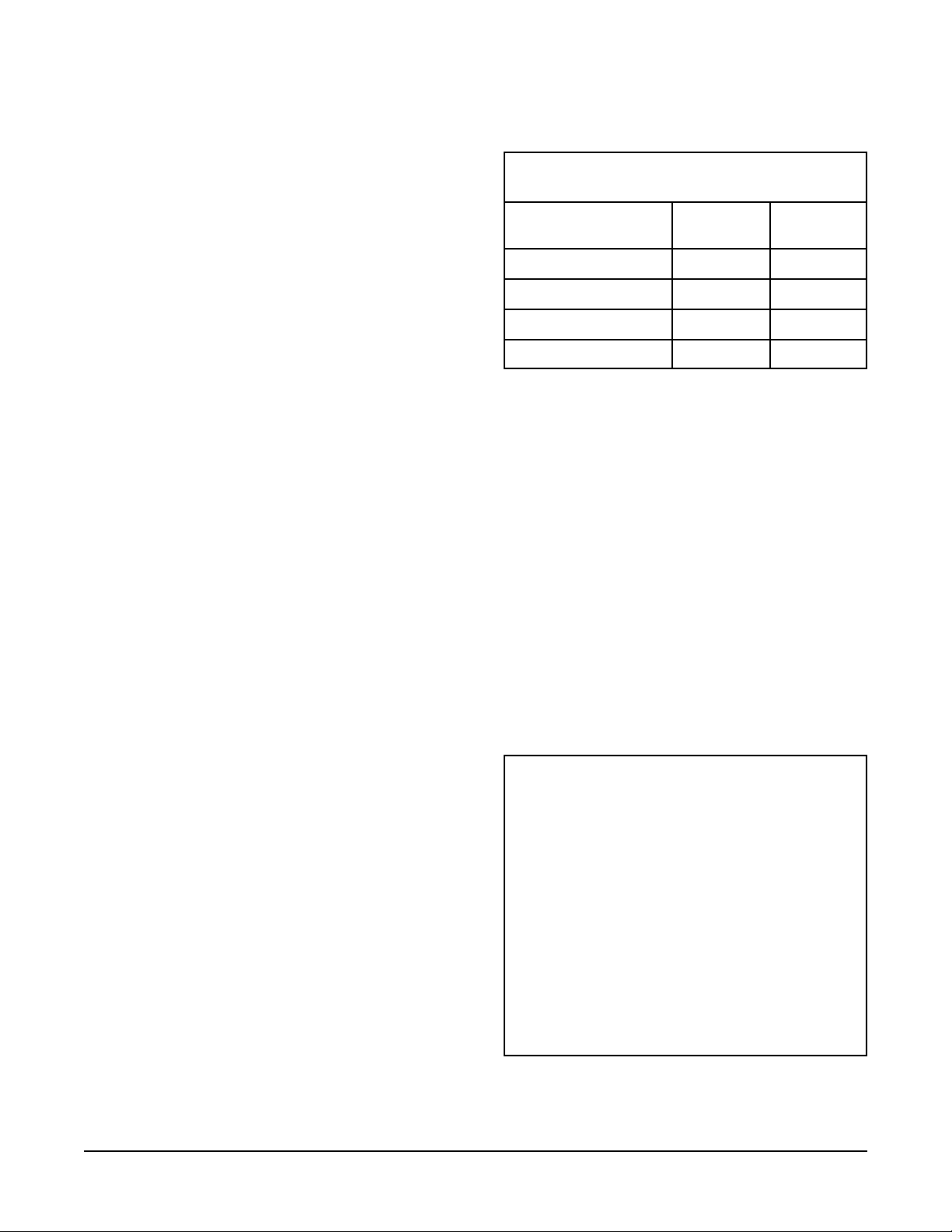
RECOMMENDED TRACK SUPPORT SPACING
Using 106 Clamp Hanger (in feet)
Curtain Weight
Per Carrier (pounds)
268
368
4 6 7.5
55.57
For additional information, please refer to Catalog Fourteen,
pages 62-63. For tracks 10 feet or less in length it is
recommended that the track be supported at a minimum of three
locations.
110A 110S
Pivot Devices
1. Pivot devices allow for curtains to be positioned at different
angles relative to the track. The 10, 10B, 10X, and 10XB are
free-wheeling units. The addition of the optional 10BK and
10BKB brake kit will prevent undesired movement of pivot
along track.
2. The pivot devices are designed for either 1-3/8" O.D. tubing
or 1" Sch. 40 pipe. Maximum recommended batten length is 6'0". Make sure that the batten is the proper length for the
application.
3. Install the "C" clamps in each end of the curtain batten.
These are provided so that a cord may be tied between the two
to aid in turning the device. The cord should be long enough so
that adjustment may be done with the curtain at its proper trim.
4. WARNING! Tracks that include pivot devices must be
provided with a bolt through style end stop (111) to contain
the pivot device within the track assembly.
4. CAUTION! Do not attempt to adjust the curtain by
means of pulling on the fabric. Damage to the curtain and
associated hardware may result.
5. CAUTION! The recommended total load on the device
must not exceed 75 pounds.
All recommendations stated are presented in good faith and
based upon generally accepted engineering principles. The user,
however, is cautioned that H & H Specialties Inc. cannot
guarantee the accuracy of the data presented in this table for
every situation. It is the customer’s responsibility to determine
the suitability of H & H Specialties’ products for any given
application, taking into account the specific requirements, the
environment of use, and any possible peculiarities of the
application.
Direct ceiling attachment of tracks has not been evaluated as the
support structure, method of attachment, and attachment
requirements may vary widely from project to project. A
qualified person should be consulted for this application.
DISCLAIMER
This product is designed for moving curtains or, in
some cases, scenery.
NONE OF THE ITEMS DESCRIBED HEREIN ARE
DESIGNED, INTENDED OR WARRANTED FOR
THE USE OF LIFTING OR TRANSPORTING
PEOPLE OR OTHER LIVING OBJECTS.
Rear Fold Guide
1. Rear fold guides (112 or 113) are used when the curtain
needs to store in a pocket or a "sliding door" effect is desired.
2. The guide is attached to the carrier and is positioned offstage
in relation to the carrier. Rubber bumpers are place on each side
of the guide to insure quiet operation. Note: The master carrier
and carrier nearest the end pulley do not require a rear fold
guide.
H & H Specialties Inc. makes no representation of the
suitability of any product for any application unless
specific design drawings are made by the factory and
the products are installed in precisely the manner
detailed by our design staff.
H & H Specialties Inc. 100 Series Installation
South El Monte, CA 91733 February 20, 2007
Page 3 of 3

&
100 SERIES STANDARD-DUTY STRAIGHT TRACK
106 CLAMP HANGER
104 SINGLE
END PULLEY
101 CARRIER
102 MASTER CARRIER
105 OVERLAP CLAMP
109 END STOP
103 DOUBLE END PULLEY
COMPLETE TRACK
MODEL NUMBERS
101A 116A
101S 116S
101W 116W
BLACK
COMPLETE TRACK
MODEL NUMBERS
101SB 116SB
101WB 116WB
2 polyethylene wheels riveted to plated steel
SINGLE CARRIER
body with swivel hook.
No. 101 - Zinc plated.
No. 101B - Black finish.
OVERLAP CLAMP
Formed steel clamps to align track at overlap.
1 set pictured.
No. 105 - Zinc plated.
No. 105B - Black finish.
MASTER CARRIER
4 polyethylene wheels riveted to steel body
with 2 swivel hooks. Supplied with 2 clamps
for anchoring operating line or cable. 1 pair
required for overlapping tracks.
No. 102 - Zinc plated.
No. 102B - Black finish.
CLAMP HANGER
Formed steel brackets clamp to track.
Adjusts to any position. Suspend track with
welded chain or wire rope.
1 pair pictured.
No. 106 - Zinc plated.
No. 106B - Black finish.
DOUBLE END PULLEY
2-1/2" diameter Nylatron GS sheaves with
shielded ball bearings. Steel housing clamps
to underside of track. Chain bracket for securing offstage curtain edge.
No. 103 - Zinc plated.
No. 103B - Black finish.
SPLICE
Formed steel brackets align and lock track
sections together. 1 pair pictured.
No. 107 - Zinc plated.
No. 107B - Black finish.
SINGLE END PULLEY
2-1/2" diameter Nylatron GS sheave with
shielded ball bearing. Steel housing clamps to
underside of track. Chain bracket for securing
offstage curtain edge.
No. 104 - Zinc plated.
No. 104B - Black finish.
No. 108 BLACK
ADJUSTABLE FLOOR BLOCK
4" diameter Nylatron GS sheave with shielded
ball bearing in steel housing.
9" vertical adjustment.
No. 108DK BLACK DETACHABLE
FLOOR BLOCK KIT
7 gauge steel plate with hardware for use
with No. 108 Adjustable Floor Block for
quick release.
4
END STOP & CORD SUPPORT
Steel clamp with eye to support operating line
and prevent carriers from traveling beyond
desired location. 1 pair required for overlapping tracks.
No. 109 - Zinc plated.
No.109B - Black finish.
Mill finish 6063-T5 extruded aluminum 1-3/4"
No. 110A TRACK
wide x 2" high,.080" thick. 20' and 24' stock
lengths.
16 gauge galvanized steel, roll-formed to 1-3/4"
TRACK
wide x 2" high.
No. 110S- 8', 10', 12', 16', 18', 20', 24', and
26' stock lengths.
No. 110S-B- Semi-gloss black powder
coat finish. 16', 20', and 24'
stock lengths.

&
Bolt with horizontal pipe spacer to prevent
END STOP
carriers from traveling beyond desired location. For use with walk-along tracks.
No. 111 - Zinc plated.
No. 111B - Black finish.
SINGLE CARRIER
2 nylon-tired shielded ball bearing wheels
riveted to steel body with swivel hook
and trim chain. Supplied with 1 rubber
bumper.
No. 116 - Zinc plated.
No. 116B - Black finish.
Allows curtain to fold at offstage edges. Supplied
REAR FOLD GUIDE
with 1 rubber bumper.
No. 112 - for use with 1/4" operating line.
No. 112B - same as 112 in Black.
No. 113 - for use with 3/16" operating cable.
No. 113B - same as 113 in Black.
Note: Cannot be used with No. 132 Overlap
Master.
MASTER CARRIER
4 nylon-tired shielded ball bearing wheels
riveted to steel body with 2 swivel hooks and
trim chains. Supplied with 2 rope clamps
and 1 rubber bumper. 1 pair required for
overlapping tracks.
No. 117 - Zinc finish.
No. 117B - Black finish.
No. 114 OPERATING LINE
1/4" diameter black polyester braided over
solid aramid core for manual operation.
CENTER PIPE SUPPORT
Formed steel bracket used to support tracks
at overlap.
No. 126 - Zinc plated.
No. 126B - Black finish.
OPERATING CABLE
Black polyester jacket braided over 3/32"
galvanized aircraft cable. For use with
motorized tracks.
No. 115 - 3/16" diameter
No. 125 - 1/4" diameter
CEILING SPLICE
To align and lock track sections together on
ceiling mounted tracks. 1 pair pictured.
Note: Cannot be used with No. 132 Overlap
Master or No. 10 Pivot Device due to
interference with the wheels.
No. 127 - Zinc plated.
No. 127B - Black finish.
No. 130 ROUND RUBBER BUMPER
1/8" neoprene bumper placed between
carriers to reduce noise.
PIVOT DEVICE
Heavy steel construction with nylon wheels.
Supplied with brackets for 1-3/8" O.D. pipe
or tubing (6' max. recommended length).
Allows masking draperies to be rotated to
any angle.
Working Load Limit: 75 pounds.
No. 10 - Zinc plated.
No. 10B - Black finish
OVERLAP MASTER
1-3/4" O.D. nylon wheels riveted to steel
body with 9" offset arm. Used to overlap
curtains on continuous track. Clamps
provided to secure operating line. 1 pair
required for overlapping curtains.
No. 132 - Zinc plated.
No. 132B - Black finish.
INDEXING PIVOT DEVICE
Pivot device with special plate to index rotation at 22-1/2 degree increments. Supplied
with brackets for 1-3/8" O.D. pipe or tubing
(6' max. recommended length).
Working Load Limit: 75 pounds.
No. 10X - Zinc plated.
No. 10XB - Black finish.
No. 134 BLACK SIDE MASKING
MASTER CARRIER
No. 117 Master Carrier with 3-3/4" x 5-3/4"
steel plate for attaching side masking frame.
Supplied with 2 rope clamps.
BRAKE KIT
Spring equipped arm with neoprene pad. Add
to pivot device to prevent undesired movement
along track.
No. 10BK - Zinc plated.
No. 10BKB - Black finish.
3 links No.10 single jack chain added
TRIM CHAIN
to carriers to provide 3" of curtain height
adjustment.
No. 135 - Zinc plated.
No. 135B - Black finish.
No. 454 Curtain Machine
See pages 50-61
for curtain machines
5

&
GENERAL SPECIFICATIONS:
STANDARD-DUTY STRAIGHT TRACK
Provide Model 101S as manufactured by H & H Specialties Inc., South El Monte, CA.
Track shall be 16 gauge galvanized steel, roll-formed to 1-3/4" wide X 2" high with continuous slot in bottom. Provide unspliced
in lengths up to 26'.
Suspend track with two-piece clamp hanger formed from 11 gauge steel. Provide 2' overlap at center, rigidly separated by two
overlap clamps. Install end stop with cord support at each overlapping track end. Where lengths exceed 26', connect tracks with
12" long, two-piece splicing clamp of 12 gauge steel.
Provide single carriers, spaced on 12" centers, constructed of two polyethylene wheels fastened parallel to formed steel carrier
body with swivel hook for attachment of curtain.
Master carriers shall be 4-wheel assemblies with formed steel bodies and two swivel hooks each. Connect to operating line with
two machined steel cord clamps captured within each body.
Single and double end pulleys shall clamp securely to the underside of the track channel and shall contain 2-1/2" diameter sheaves
enclosed in steel housings to prevent operating line from escaping the grooves. Nylatron GS sheaves shall be molded around
shielded and greased ball bearings and grooved to accommodate up to 1/4" operating line.
Provide floor block in 12 gauge steel housing containing 4" Nylatron GS shielded ball bearing sheave. Sheave axle shall lock at
any point within 9" vertical slots to allow tension adjustment of operating line.
Black operating line shall be 1/4" diameter, stretch-resistant rope with spun polyester outer jacket braided over solid aramid
core.
All steel components shall be zinc plated to resist corrosion.
100 SERIES COMPLETE TRACK COMPONENT GUIDE
For COMPLETE tracks supplied with aluminum, substitute 110A for 110S.
PART No. DESCRIPTION 101S 101W 116S 116W
101 Single Carrier
102 Master Carrier
103 Double End Pulley
104 Single End Pulley
105 Overlap Clamp
106 Clamp Hanger
107* Splice
108 Black Adjustable Floor Block
109 End Stop & Cord Support
110S* Track
114 1/4” Operating Line
116 Nylon B.B. Single Carrier
117 Nylon B.B. Master Carrier
ŏŏ
ŏŏ
ŏŏ
ŏŏ
ŏŏ
ŏŏŏŏ
ŏŏŏŏ
ŏŏ
ŏŏŏŏ
ŏŏŏŏ
ŏŏ
ŏŏ
ŏŏ
* Track lengths and splices supplied as required from stock sizes.
100 SERIES BLACK COMPLETE TRACK COMPONENT GUIDE
Note: Aluminum track is not offered in black.
PART No. DESCRIPTION 101SB 101WB 116SB 116WB
101B Black Single Carrier
102B Black Master Carrier
103B Black Double End Pulley
104B Black Single End Pulley
105B Black Overlap Clamp
106B Black Clamp Hanger
107B* Black Splice
108 Black Adjustable Floor Block
109B Black End Stop & Cord Support
110S-B* Black Track
114 1/4” Operating Line
116B Black Nylon B.B. Single Carrier
117B Black Nylon B.B. Master Carrier
ŏŏ
ŏŏ
ŏŏ
ŏŏ
ŏŏ
ŏŏŏŏ
ŏŏŏŏ
ŏŏ
ŏŏŏŏ
ŏŏŏŏ
ŏŏ
ŏŏ
ŏŏ
* Track lengths and splices supplied as required from stock sizes.
6

106 CLAMP HANGER
&
100 SERIES TRACK
2'-0" OVERLAP
PLAN - MODEL 101S COMPLETE TRACK
104 SINGLE
END PULLEY
1-3/4"
2"
110 TRACK
101 CARRIER
10 PIVOT DEVICE
4-1/8"
2-1/16" C TO C
TRACKS AT CENTER
OVERLAP
105 OVERLAP CLAMP
109 END STOP & CORD SUPPORT
102 MASTER CARRIER
ELEVATION - MODEL 101S COMPLETE TRACK
5-3/4"
108 BLACK ADJUSTABLE FLOOR BLOCK
5-1/8"
2"
101 SINGLE CARRIER AND 102 MASTER CARRIER
103 DOUBLE END PULLEY
114 OPERATING LINE
3/8"Ø
1-1/8"
2-3/4"
1-5/8"
2-5/8"
4-13/16" 3-1/8"
104 SINGLE END PULLEY
2-7/8"
4" 4"
3-1/8"
4-13/16"
2-3/16"
103 DOUBLE END PULLEY
7
 Loading...