

Page 1

Location Sound Recorder
Operations Manual
Version 1.31 October 2004
Page 2

Page 3

Version 1.31
PORTADRIVE KEY FEATURES
• Rugged, all in one, portable 8-channel hard disk (HD) audio recorder
• Three comprehensively equipped 6-into-2 digital mixers built-in
• Session based recording using either AES31-3 ADL or Pro Tools V5 formats, simplifying production
workflow
• Over four hours of uncompressed 8-channel 24-bit/96kHz or around twenty hours of 4-channel 24-
bit/48kHz recording on removable 40GB HD
• Simultaneous recording of mono or stereo rushes to external DVD-RAM drive or other storage device
• Six high gain, very low noise microphone balanced XLR-3 inputs with individual phantom powering,
‘gangable’ limiters, input pads, high pass filter (HPF), and phase reverse
• Mic inputs also feature adjustable delays for use with radio mics
• Eight balanced line inputs
• Dual analogue balanced stereo outputs
• 8-channel AES input and output, stereo SPDIF input and output
• M/S decoding available on inputs and outputs
• Advanced power management
• Built-in battery charging circuitry
• 8-channel metering with clip and limiting indicators
• Built-in slate mic and tone generator
• Extensive headphone monitoring capability including designated 6-into-2 mixer
• Six multi-function rotary encoders
• Ten second pre-record buffer
• Top and front panel LCD and control interfaces
• Comprehensive timecode and synchronization capability
• Supports tri-level synchronization for compatibility with HDTV technology
• 2.5" HDD in robust removable caddy ensures extremely reliable recording
• HD compatible with both PC and Mac platforms (FAT32, HFS)
• Records in industry-standard BWF or SDII audio formats
• Metadata (scene, take, comments) can be stored and transferred with audio files
• SCSI interface
• USB2.0 (USB1 compatible) port for high speed data transfer between the PORTADRIVE and a
computer (software version 1.4)
• Ethernet port for file transfer
• Comprehensive remote control via a parallel remote socket
• PS2 for connecting keyboard to ease logging / labelling
• Optional 5.25" PDRDS Docking Station allows removable HD caddy to be plugged directly into a
computer drive bay or external drive enclosure
• Optional DC-powered PDRDVDBU DVD-RAM backup unit for recording or backing up on location
Page 4

B Version 1.31
REGISTRATION
Please register ownership of your PORTADRIVE now at http://www.hhb.co.uk. Select your location
and click on the REGISTER tab at the top of the page. Registration will enable you to receive software
updates and other important PORTADRIVE product news.
EC DECLARATION OF CONFORMITY
This equipment conforms to the requirements of the EMC Directive (89/336/EEC) relating to
electromagnetic compatibility by the application of: - EN55013: 2001 and EN55020: 2002
LIMITED SOFTWARE WARRANTY POLICY
All the software provided with, or purchased especially for, HHB products has been tested for
functionality. HHB Communications Ltd will make all reasonable efforts to correct reported software
defects for future releases subject to technical and economic practicality. HHB Communications Ltd
makes no warranty or representation either express or implied with respect to the system's
performance or fitness for a particular purpose.
In no circumstances will HHB Communications Ltd be liable for direct or indirect damages arising from
any defect in the software or its documentation. Further, HHB Communications Ltd will not be liable for
any loss of or damage to programs, sounds, audio recording, sequences or data stored in or used with
HHB products, including the cost of recovery.
The disclaimers above are exclusive and take precedence over all others, oral or written, express or
implied, to the extent permitted by law in the geographical area of the product's sale. No employee of
HHB Communications Ltd, agent, distributor or employee of an agent or distributor is authorised to
offer any variation.
TRADEMARKS
Digidesign and Pro Tools are registered trademarks of Digidesign and/or Avid Technology, Inc.
Macintosh is a registered trademark of Apple Computer Inc. All other trademark, product and company
names are the property of their respective owners.
FURTHER INFORMATION
To obtain further information relating to the HHB PORTADRIVE PDR2000 please visit
http://www.portadrive.info
Page 5

Version 1.31
TABLE OF CONTENTS
PORTADRIVE KEY FEATURES.........................................................................................................A
REGISTRATION ..................................................................................................................................B
CONFORMITY ........................................................................................................................B
SOFTWARE WARRANTY .....................................................................................................B
TRADEMARKS.......................................................................................................................B
FURTHER INFORMATION ....................................................................................................B
TABLE OF CONTENTS ......................................................................................................................C
RIGHT SIDE PANEL ...........................................................................................................................1
MIC/LINE INPUTS ..................................................................................................................2
MAIN L/R OUTPUTS..............................................................................................................2
AUX L/R OUTPUT..................................................................................................................2
AES/EBU OUT........................................................................................................................2
2 CH RETURN ........................................................................................................................3
HEADPHONE OUTPUT .........................................................................................................3
TIMECODE INPUT / OUTPUT ...............................................................................................3
WORDCLOCK OUTPUT ........................................................................................................3
SYNC INPUT ..........................................................................................................................3
SPDIF INPUT/OUTPUT..........................................................................................................4
AES 8-CHANNEL I/O D-SUB CONNECTOR ........................................................................4
LEFT SIDE PANEL..............................................................................................................................5
BATTERY COMPARTMENT..................................................................................................6
DC INPUT ...............................................................................................................................6
REMOVABLE DISK DRIVE CADDY .....................................................................................7
PS2 KEYBOARD INPUT........................................................................................................7
PARALLEL REMOTE CONNECTION ...................................................................................7
RS422 PORT ..........................................................................................................................8
USB2 CONNECTION .............................................................................................................8
ETHERNET CONNECTION ...................................................................................................8
SCSI-2 CONNECTION ...........................................................................................................8
PDR2000 FRONT PANEL...................................................................................................................9
METERS .................................................................................................................................10
MODE KEYS...........................................................................................................................11
LCD / ENCODERS / SOLO KEYS .........................................................................................12
TRANSPORT CONTROL.......................................................................................................13
HEADPHONE CONTROL ......................................................................................................15
DISPLAY KEY ........................................................................................................................16
LIGHT KEY .............................................................................................................................18
MARK KEY .............................................................................................................................18
ERROR LED ...........................................................................................................................18
UTILITY KEYS........................................................................................................................19
UNDO......................................................................................................................................19
JAM TC...................................................................................................................................19
SLATE ....................................................................................................................................20
TONE ......................................................................................................................................20
GROUP ...................................................................................................................................20
INTERNAL MICROPHONE ....................................................................................................20
Page 6

D Version 1.31
FRONT PANEL MODES .....................................................................................................................21
INPUT MODE..........................................................................................................................21
BUSMIX MODE ......................................................................................................................24
TRACK MODE........................................................................................................................26
OUTPUT MODE......................................................................................................................29
HEADPHONE SETUP MODE ................................................................................................34
MANAGING METADATA.......................................................................................................37
PDR2000 TOP PANEL........................................................................................................................41
POWER SWITCH ...................................................................................................................42
TRANSPORT CONTROLS ....................................................................................................43
PANEL ON / OFF ...................................................................................................................44
MODE KEYS...........................................................................................................................44
SPEAKER...............................................................................................................................45
LCD.........................................................................................................................................45
CURSOR KEYS / DATA WHEEL...........................................................................................46
ENTER KEY............................................................................................................................46
LIGHT KEY .............................................................................................................................46
PROGRAMMABLE KEYS......................................................................................................46
USING THE TOP PANEL SCREENS ....................................................................................47
NAMING ITEMS ON THE PORTADRIVE ..............................................................................48
ABOUT THE TOP PANEL MODES .......................................................................................49
TOP PANEL MODES ..........................................................................................................................50
INPUT MODE..........................................................................................................................50
INPUT SOURCE........................................................................................................50
LIMITER .....................................................................................................................51
PHASE REVERSE.....................................................................................................51
INPUT LEVEL ............................................................................................................52
BUSMIX MODE ......................................................................................................................54
LEVELS......................................................................................................................54
PANS .........................................................................................................................54
MS DECODE .............................................................................................................54
TRACK MODE........................................................................................................................56
TRACK ARMING WITH BWF FORMATS .................................................................57
OUTPUT MODE......................................................................................................................58
MAIN OUTPUT ..........................................................................................................58
AUX OUTPUT ............................................................................................................59
HEADPHONE ............................................................................................................60
DISK MODE............................................................................................................................68
FORMAT DISK...........................................................................................................71
PRO TOOLS V5 (SDII) or AES31 (BWF) ..................................................................71
NAVIGATING DISKS .................................................................................................74
DISK / FILE HIERARCHY..........................................................................................75
COPYING ITEMS.......................................................................................................78
CREATING A NEW FOLDER OR SESSION ............................................................79
SESSION MODE ....................................................................................................................81
TAKE INFO ................................................................................................................82
MANAGING METADATA...........................................................................................83
CREATING A NEW SESSION...................................................................................87
SAMPLE RATE ..........................................................................................................88
BIT-DEPTH ................................................................................................................88
MULTI-SESSION SUPPORT.....................................................................................89
BROADCAST WAVE (BWF) SUPPORT ...................................................................90
BWF FORMAT SELECTION .....................................................................................91
TC MODE................................................................................................................................92
TIMECODE SETTINGS .............................................................................................92
USER BITS ................................................................................................................93
TIMECODE CHASE...................................................................................................94
TIMECODE JAM ........................................................................................................97
SETUP MODE ........................................................................................................................98
Page 7

Version 1.31
TONE GENERATOR .................................................................................................98
SLATE........................................................................................................................99
POWER MANAGEMENT...........................................................................................100
BATTERY CHARGE ..................................................................................................100
LCD CONTRAST .......................................................................................................101
WORDCLOCK SYNC ................................................................................................102
MISCELLANEOUS SETTINGS .................................................................................103
TEMPLATES..............................................................................................................106
P1 - P2 ASSIGN.........................................................................................................108
METERING OPTIONS...............................................................................................109
OS UPDATE ..............................................................................................................110
DATE / TIME SETUP.................................................................................................111
LOCATE .................................................................................................................................113
LOCATE TAKE ..........................................................................................................113
LOCATE MARK .........................................................................................................114
LOCATE TIMECODE.................................................................................................115
AUDITION ..................................................................................................................115
APPENDICES......................................................................................................................................116
TRANSFERRING TO ANOTHER SYSTEM........................................................................................116
FACTORY TEMPLATES.....................................................................................................................118
CONNECTOR PINOUTS.....................................................................................................................119
DC POWER CONNECTOR ....................................................................................................119
PARALLEL REMOTE ............................................................................................................119
AES AUDIO I/O ......................................................................................................................120
TIMECODE CONNECTOR.....................................................................................................120
RS422 9-PIN CONNECTOR...................................................................................................120
2 CHANNEL RETURN ...........................................................................................................121
ANALOGUE AUDIO INPUT ...................................................................................................121
ANALOGUE AUDIO OUTPUT...............................................................................................121
NOTES ON USING EXTERNAL SCSI HARD DISK DRIVES ............................................................122
WHAT IS SCSI? .....................................................................................................................122
SCSI IDs .................................................................................................................................122
SCSI CABLES ........................................................................................................................123
TERMINATION .......................................................................................................................123
CABLE LENGTH ....................................................................................................................123
SPECIFICATIONS ...............................................................................................................................124
Page 8

F Version 1.31
This Page Is Intentionally Left Blank.
Page 9
SIDE PANELS/CONNECTIONS
Version 1.31 1
Page 10
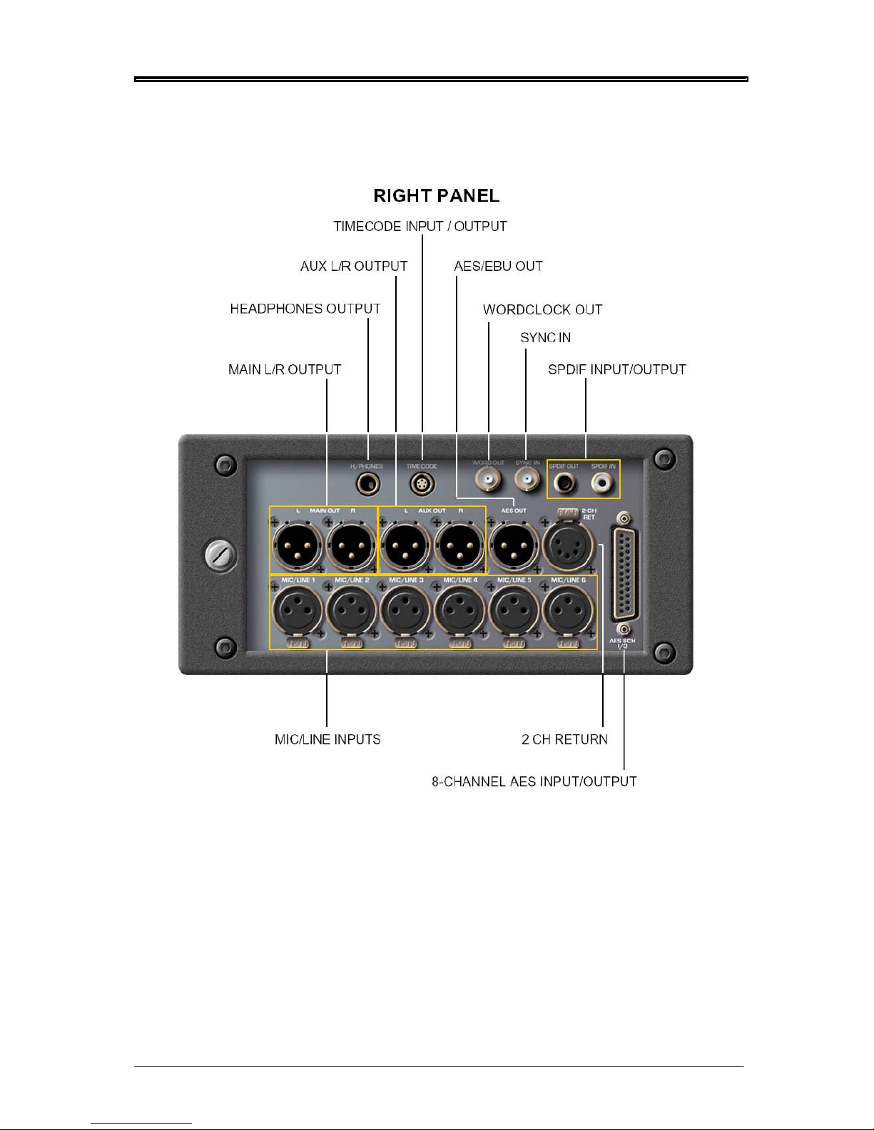
SIDE PANELS/CONNECTIONS
The PORTADRIVE is comprehensively equipped with a wide range of professional audio and
synchronisation connectors. These are located on the right side panel. They are as follows:
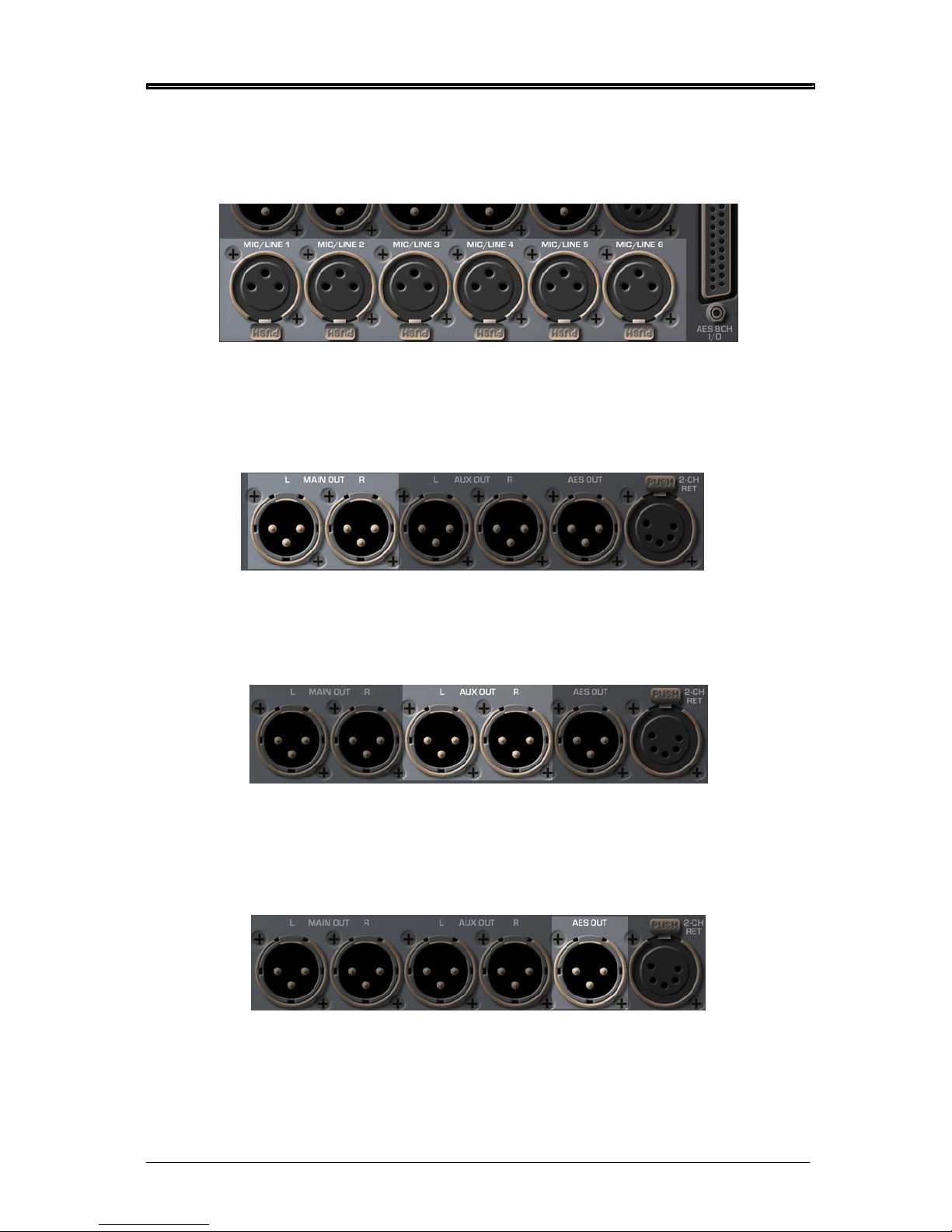
MIC/LINE INPUTS
These six balanced XLR inputs can accept both microphones and line level signals. When used as a
microphone input, each channel has (switchable) phantom power for use with condenser
microphones.
MAIN L/R OUTPUTS
Carries a stereo or 2-mono channel signal (which can be derived from a large variety of sources) on
balanced XLR connectors.
AUX L/R OUTPUT
This is an additional stereo or 2-mono channel output source and can be used to carry an alternative
mix on balanced analogue XLR connectors. Like the MAIN L/R OUTPUT, the AUX OUTPUT can be
derived from a large number of sources.
AES/EBU OUT
This digital output can be OFF, MAIN OUT, AUX OUT or TRACKS L&R.
It is not necessarily a stereo mix - it might be 2 mono channels or just one mono channel if one
channel is muted.
2 Version 1.31
Page 11
SIDE PANELS/CONNECTIONS
Version 1.31 3
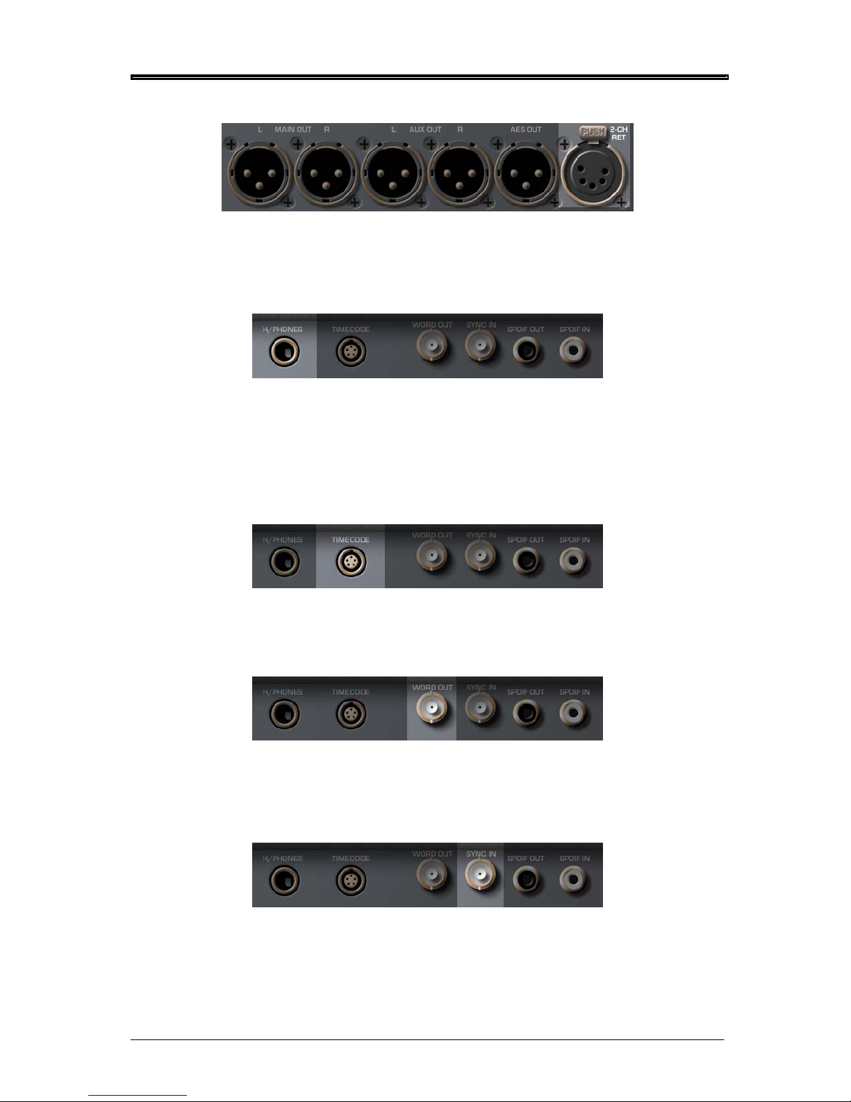
2 CH RETURN
This analogue connection provides an extra pair of line inputs that can be used for a variety of
purposes.
HEADPHONE OUTPUT
A stereo or 2-mono channel headphone output for private monitoring. The audio at the headphone
output can be set to follow whatever is selected for metering (e.g. inputs, track, outputs etc.) so that
what you see is what you hear. It can also take as its source a wide variety of other signals easily
selectable as pre-configured user presets.
TIMECODE INPUT / OUTPUT
This allows you to slave to external timecode or act as a master timecode source.
WORDCLOCK OUTPUT
This BNC carries a wordclock signal that is equal to the PORTADRIVE’s own internal sampling
frequency. This can be used to synchronise other digital audio equipment to the PORTADRIVE.
SYNC INPUT
This BNC connector allows you to synchronise the PORTADRIVE to external wordclock, video, trilevel or digital audio sync. When external digital audio equipment is being used with the
PORTADRIVE, it is important that they are accurately synchronised - this connector allows the
PORTADRIVE to ‘slave’ to external digital audio equipment.
Page 12

SIDE PANELS/CONNECTIONS
SPDIF INPUT/OUTPUT
Carries a stereo SPDIF digital audio input and output. The SPDIF input can be assigned to INPUTS
1&2 and the SPDIF output is sourced from the same signal that is routed to the AES/EBU output.
AES 8-CHANNEL I/O D-SUB CONNECTOR
This provides 8-channels of AES/EBU digital audio input and output and can be used to connect the
PORTADRIVE to a digital mixing console or multitrack recorder.
4 Version 1.31
Page 13
SIDE PANELS/CONNECTIONS
Version 1.31 5
LEFT PANEL
BATTERY
COMPARTMENT
PS2 KEYBOARD
INPUT
REMOVABLE
DISK DRIVE
PARALLEL REMOTE
CONNECTION
DC INPUT USB ETHERNET SCSI RS422
Page 14
SIDE PANELS/CONNECTIONS
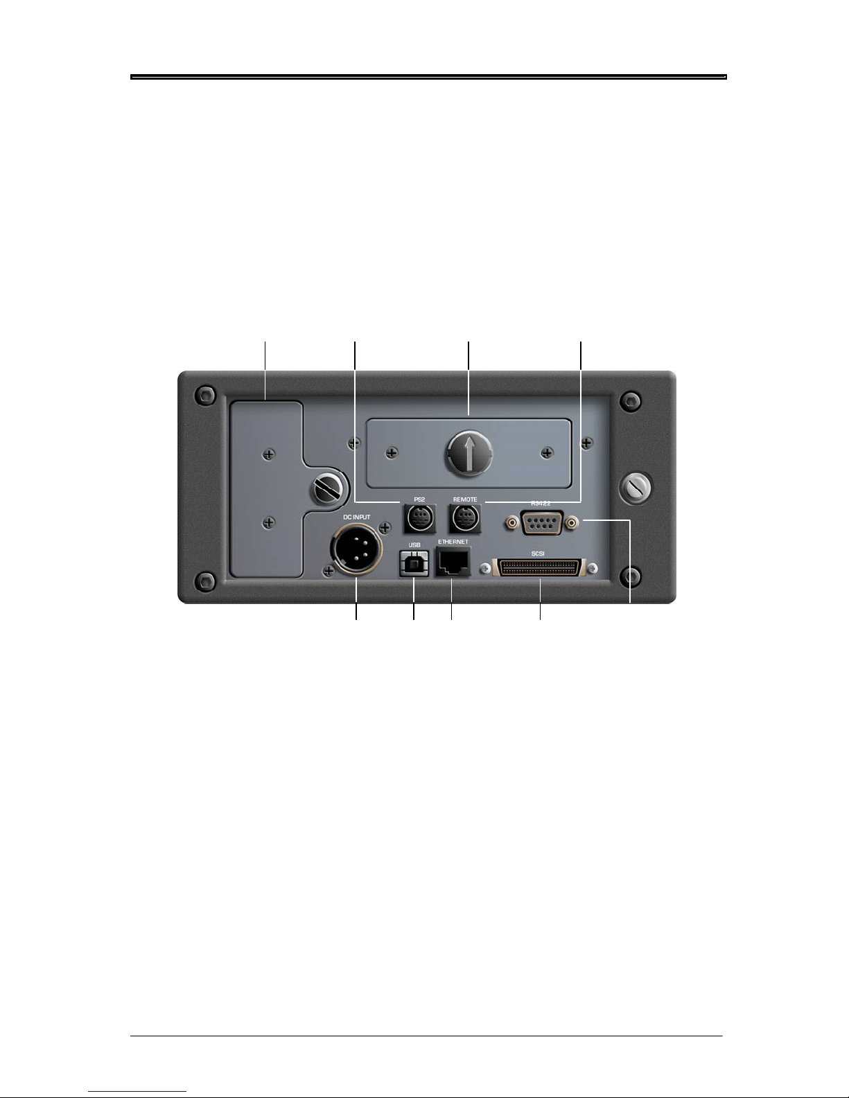
The left side panel accommodates a variety of other connections and facilities. These are:
BATTERY COMPARTMENT
This is where the LI - ION battery, NP-L50, is housed. To replace the battery, undo the large
thumbscrew and carefully remove the battery. Replace the battery and tighten the screw back up.
**** IMPORTANT ****
NEVER REMOVE THE BATTERY DURING RECORDING!
DOING SO WILL (UNDERSTANDABLY) RESULT IN LOSS OF DATA!
NEITHER SHOULD YOU REMOVE / CHANGE THE BATTERY IMMEDIATELY AFTER MAKING A
RECORDING. DOING SO MAY RESULT IN LOSS OF DATA!
Every effort has been made to safeguard data in the event of power loss and/or battery removal.
However, please exercise caution (and common sense) when removing/exchanging the battery in
order to protect your data.
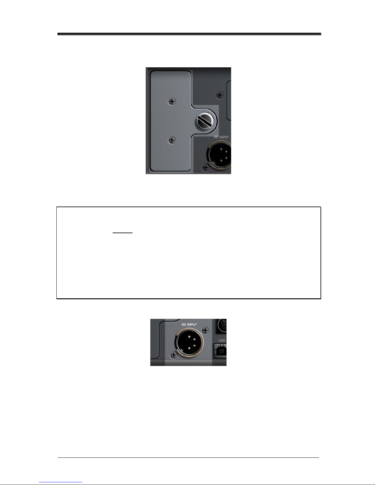
DC INPUT
This 4-pin XLR connector will accept a DC power supply from the supplied power adaptor or an
external battery with the correct rating. See PORTADRIVE Specifications on page 124 and DC Power
Connector pinout on page 119.
6 Version 1.31
Page 15
SIDE PANELS/CONNECTIONS
Version 1.31 7
REMOVABLE DISK DRIVE CADDY
This caddy houses the PORTADRIVE’s internal hard disk.
The drive caddy is removable - that is, the disk can be taken out of the PORTADRIVE and connected
to other systems via the optional HHB Docking Station.
To remove the caddy, turn the large 'screw’ in the middle counter-clockwise to the 9-o-clock position.
Now carefully pull the caddy out.
To insert a drive, reverse the above procedure -- carefully insert the caddy into the compartment and
turn the screw clockwise to the 12-o-clock position (as shown above).
**** IMPORTANT ****
Please exercise extreme caution when removing and inserting drives.
Please refer to the section that describes safe handling of disk drives on page 68.
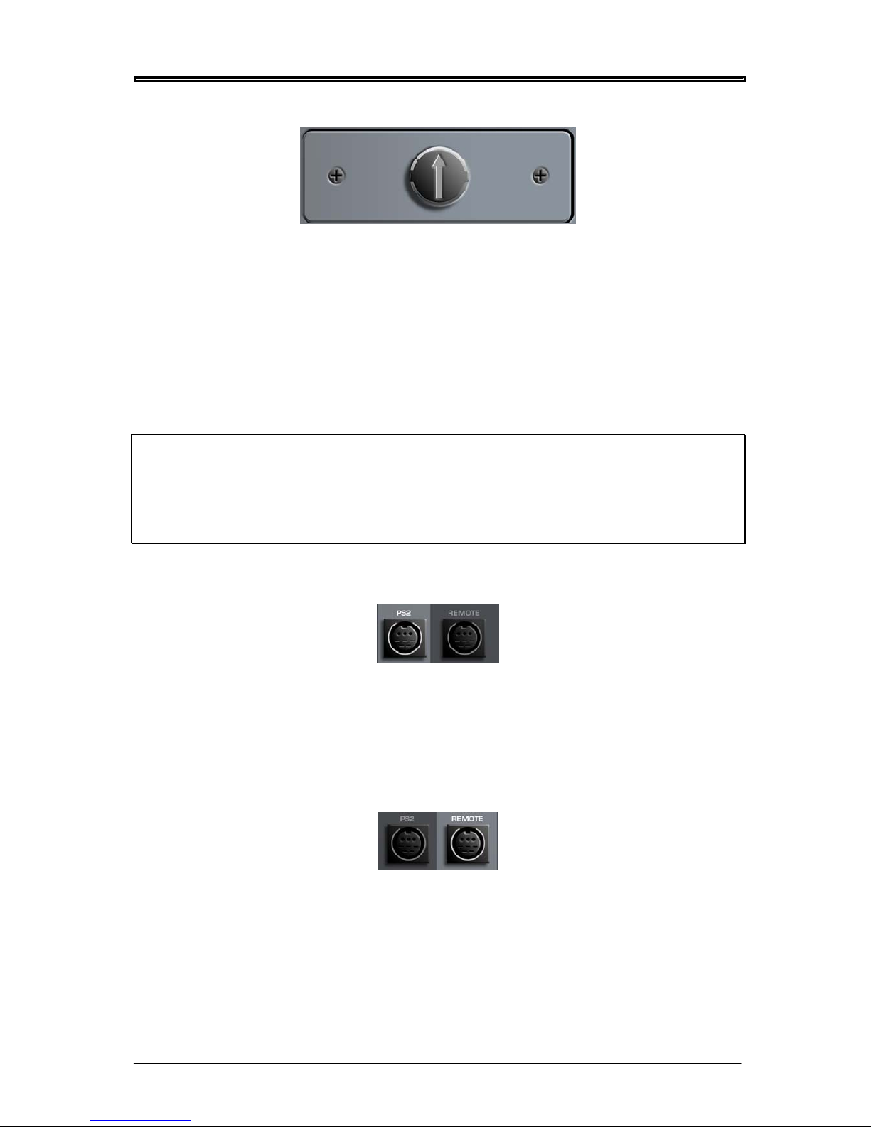
PS2 KEYBOARD INPUT
This socket allows you to connect a standard PS2 keyboard to the PORTADRIVE to make to make it
easier to input text such as scene name, notes, input name, session name etc. Input of text is still
possible without a keyboard attached (see page 48). PS2 keyboards can be purchased at any
computer store - you may already have a spare one that you use!
PARALLEL REMOTE CONNECTION
This is a parallel remote connection that allows the user to connect a simple switch based remote
control unit (not supplied). Control is implemented by shorting specific pins together. For further details
see Parallel Remote (8-Pin Mini Din) on page 119
Page 16
SIDE PANELS/CONNECTIONS
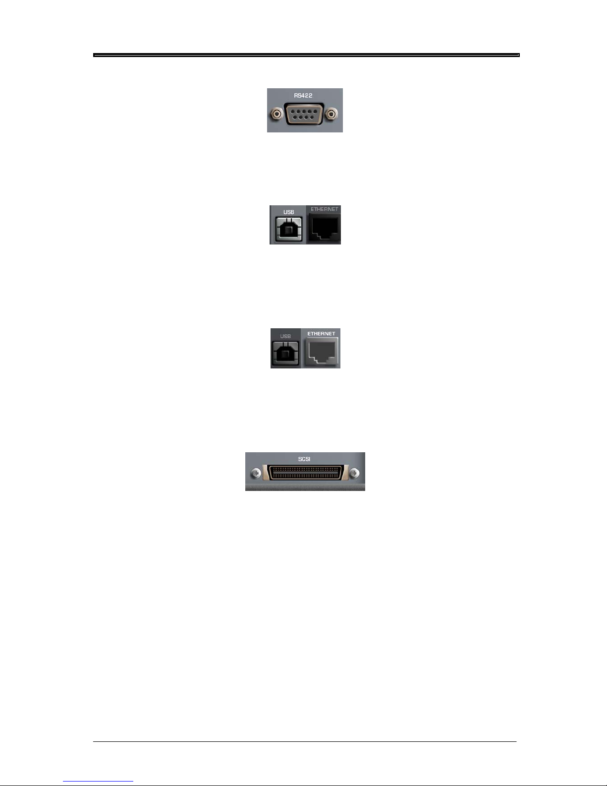
RS422 PORT
This is a future option to allow machine control using the Sony 9-pin protocol.
USB2 CONNECTION
This allows you to download operating system software updates for the PORTADRIVE from your
computer and allows the transfer of data to and from a computer (software version 1.4).
ETHERNET CONNECTION
Allows the PORTADRIVE to be connected to a network so that transfer of data to and from the
network is possible.
SCSI-2 CONNECTION
This allows you to connect to the optional HHB DVD Backup Unit (PDRDVDBU), external hard disk
drives or other forms of data storage and should be used primarily for copying data (backing up) and
recording from the PORTADRIVE.
8 Version 1.31
Page 17
FRONT PANEL
Version 1.31 Page 9
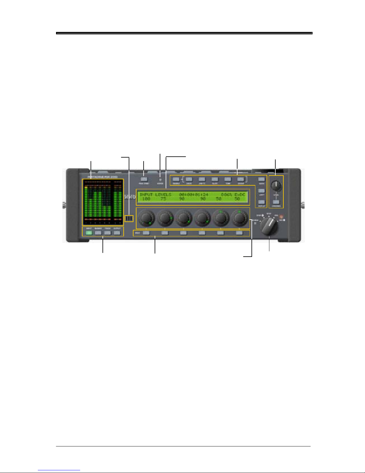
PDR2000 FRONT PANEL
METERS
PEAK
RESET
METER/MONITOR
MODE SELECT KEYS
SOLO KEYS MULTI-PURPOSE
ENCODERS
TRANSPORT
HEADPHONE
CONTROL
LCD
MIC
UTILITY
KEYS
ERROR LED
Page 18
FRONT PANEL
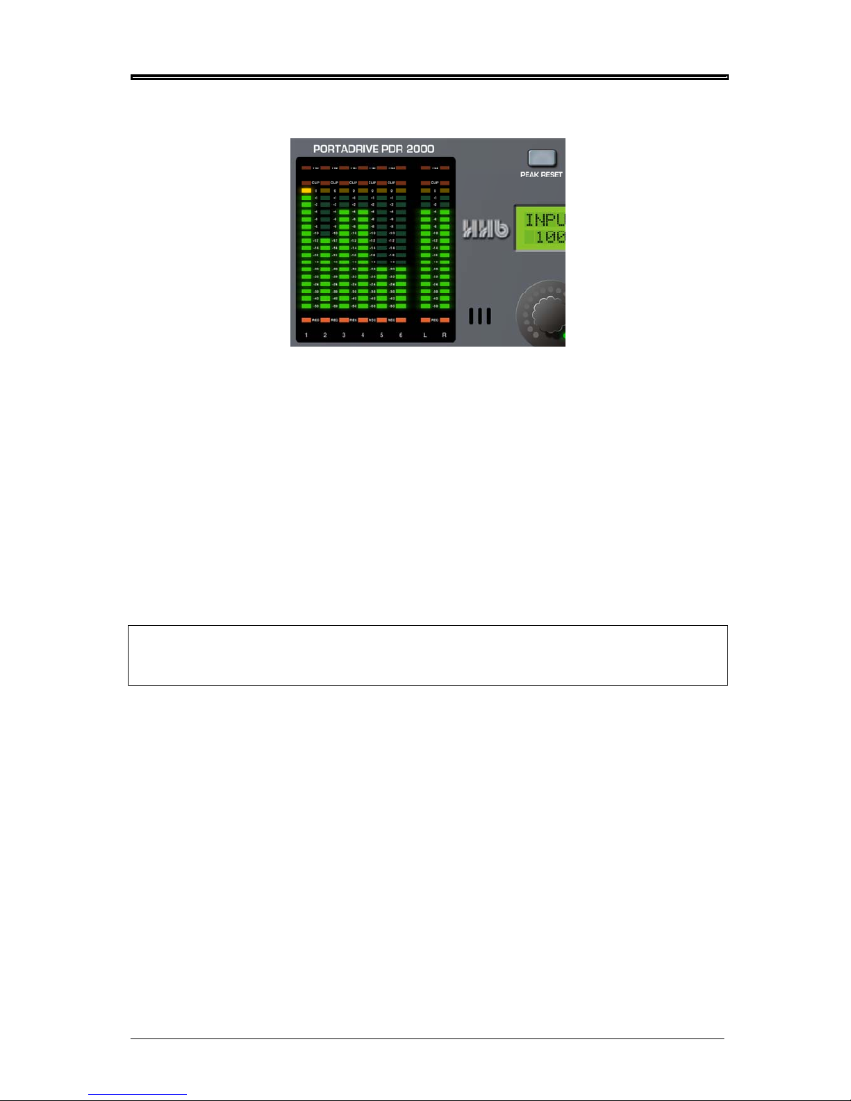
METERS
These high resolution, 18-segment meters offer detailed, precision level metering.
PEAK HOLD
The meters have a peak hold function. It is possible to set the peak hold time between OFF, ON or 1-4
seconds. These options are set in the PORTADRIVE’s SETUP mode, see page 109.
The PEAK RESET key to the right of the meters allows you to reset any held peaks. It also allows you
to reset the margins, see page 28.
LIMITER ACTIVE LEDS
At the top of the meters are 8 x LEDS that show the action of the PORTADRIVE’s soft-saturate
limiters. The six LEDs above columns 1-6 illuminate when the analogue input limiters are active.
The LEDs remain illuminated for the duration of the limiter’s action, or, in the case of a limiter switching
in when a short peak transient is received, they simply flash momentarily. The two LEDs above the L &
R columns illuminate when the 2-CH return input limiters are active.
Note - The limiter LEDs are only active when in INPUT or BUSMIX. However, the limiter LED ’s for the
2ch return do not function when in BUSMIX mode.
Also, the LIM indicators have no function for inputs whose sources are digital.
CLIP INDICATORS
These red LEDs illuminate when the signal exceeds 0dB. The clip indicators will remain illuminated for
a minimum of 2 seconds. The clip indicators will follow the PEAK HOLD duration if longer than 2
seconds.
REC ARM INDICATORS
The red REC arm indicators at the bottom of the meters indicate which tracks are enabled for record.
These LEDS will flash when the PORTADRIVE is armed for recording; the LEDs will be steadily
illuminated when recording.
10 Version 1.31
Page 19
FRONT PANEL
Version 1.31 11
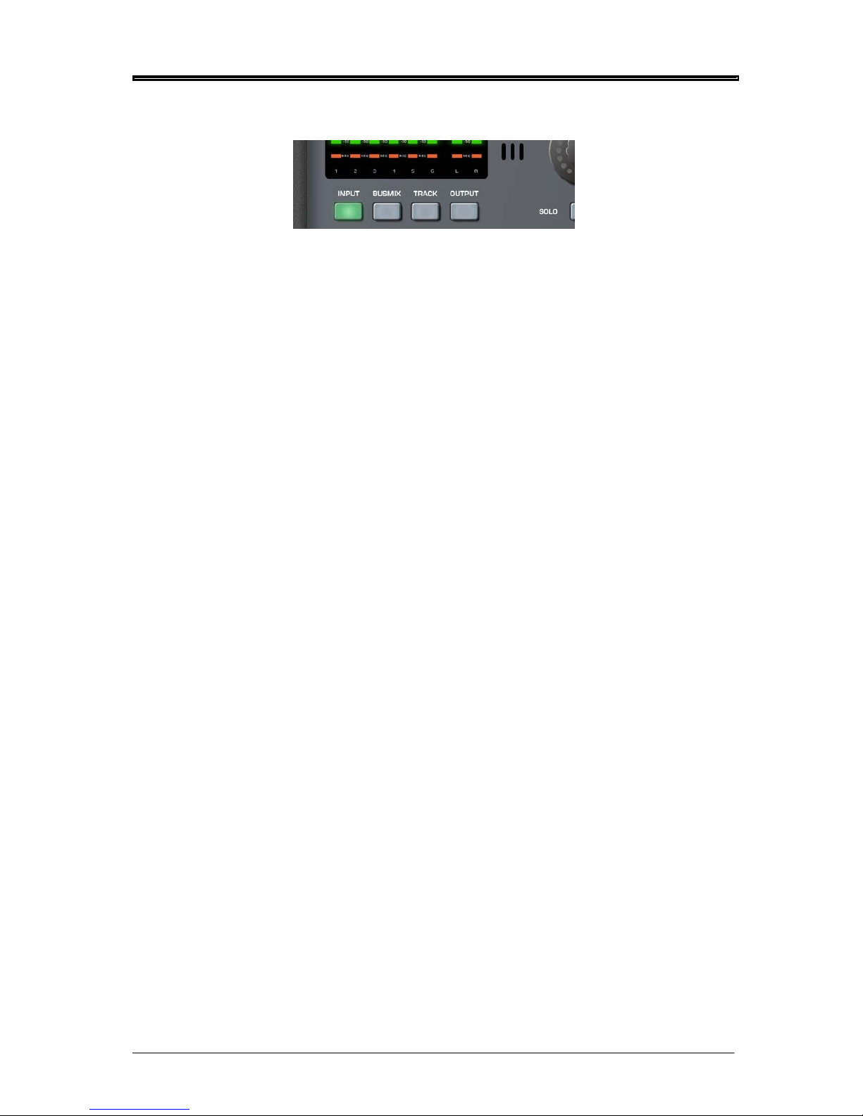
MODE KEYS
The four mode keys below the meters allow you to select the metering / monitoring.
The PORTADRIVE has three mixers, two of which (BUSMIX and OUTPUT MIX) can be selected here.
The four modes are:
INPUT
When INPUT is pressed, the meters will show input levels 1-8. Also, the LCD in the centre of the front
panel will show Page 1 of the INPUT menu. If the H/P Preset is set to ‘FOLLOW METERS’ (see page
34), the signal in the headphones will be a stereo mix of the inputs 1-6.
BUSMIX
When BUSMIX is pressed, the meters will show input levels 1-6 and the bus mixer’s stereo output.
Also, the LCD in the centre of the front panel will show Page 1 of the BUSMIX menu. If the H/P Preset
is set to ‘FOLLOW METERS’, the signal in the headphones will be the stereo output (BUSMIX L&R) of
the bus mixer.
TRACK
When TRACK is pressed, the meters will show track levels 1-8 (i.e. the level of the signal on disk).
Also, the LCD in the centre of the front panel will show Page 1 of the TRACK menu. If the H/P Preset
is set to ‘FOLLOW METERS’, the signal in the headphones will be a stereo mix of the tracks 1-6.
OUTPUT
When OUTPUT is pressed, the meters will show the MAIN L&R output signal . Also, the LCD in the
centre of the front panel will show Page 1 of the OUTPUT menu. If the H/P Preset is set to ‘FOLLOW
METERS’, the signal in the headphones will be a copy of the MAIN output signal.
If OUTPUT is pressed again, the meters will show the AUX L&R output signal and the LCD will show
page 2 of the OUTPUT menu. If the H/P Preset is set to ‘FOLLOW METERS’, the signal in the
headphones will be a copy of the AUX output signal.
If OUTPUT is then pressed for a third time, the meters will show the OUTPUT MIXER’s source 1-6 and
stereo output. The LCD will show Page 3 of the OUTPUT menu and if the H/P Preset is set to
‘FOLLOW METERS’, the signal in the headphones will be the stereo output of the OUTPUT MIXER.
When the modes are selected, the LEDs in the keys illuminate to indicate status.
Also, as you select different modes/mixer, the functions in the front panel LCD change to reflect the
selected mode/mixer.
We’ll look at each mode’s functions in more detail later in the manual. See Front Panel Modes (page
21) and Top Panel Modes (page 50).
Page 20
FRONT PANEL
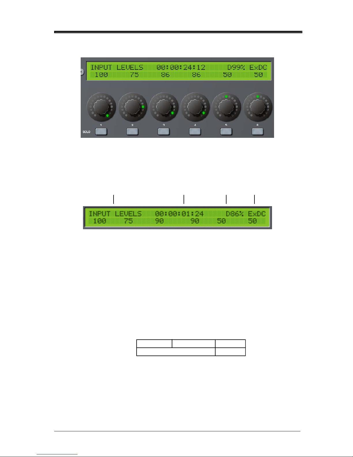
LCD / ENCODERS / SOLO KEYS
In the centre of the PORTADRIVE’s front panel is a large 40 x 2 character LCD. This is used to show
levels, pan/balance and other parameters.
The top line of the display shows general information:
CURRENT 'MODE / PAGE' 'NOW' TIME
FREE
ON DISK
BATTERY
CHARGE
The LCD also works in conjunction with the encoders below it and you will note how the parameters
on the bottom line of the LCD line up with the encoders and you can see the exact values of the
encoders on the LCD. However, the encoders have a ‘collar’ of LEDs around them that show their
position at a glance.
Portadrive detects how fast you turn a rotary encoder; the faster you turn a pot, the bigger the gain
change. This allows for much easier fade outs, fade ins and makes mixing using the rotary encoders
far more practical.
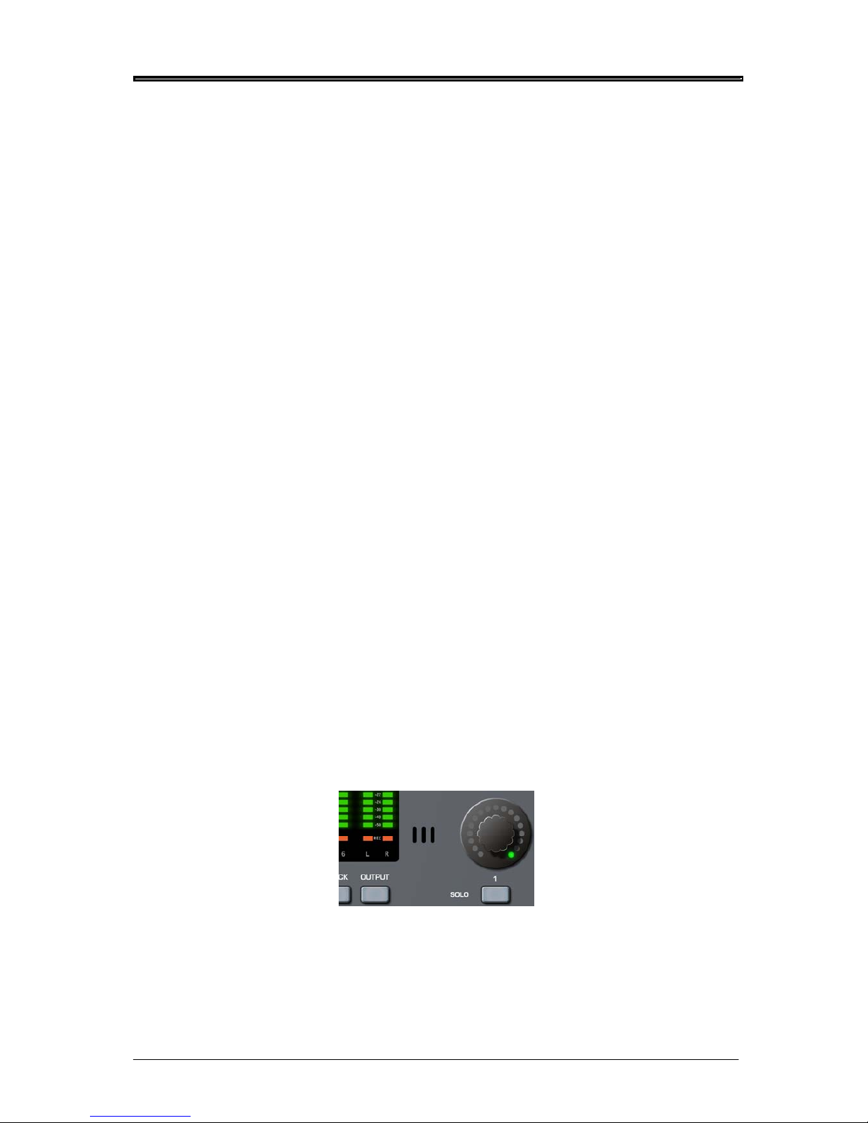
Below the encoders are six SOLO keys that allow you to listen to channels/tracks in isolation. The
solo’d signal only appears (in mono) in the headphone mix - it does not get recorded to disk, neither
will it appear at the main L/R output. Thus it’s possible to solo any channel whilst recording without
affecting the recording in any way.
What gets solo’d depends on the PORTADRIVE’s status:
RECORDINGSTOPPED PLAYING
Inputs Tracks
STATUS
SOLO
It is possible to solo any number of channels / tracks simultaneously. The input solo signal is post the
input fader.
By default, pressing a channel’s SOLO key will solo that channel and the selected key will illuminate press the key again to ‘un-solo’ it. However, depending on the way you like to work, there are various
options for how the SOLO keys react - these are available in the top panel’s HEADPHONE OUTPUT
window. See page 61.
12 Version 1.31
Page 21
FRONT PANEL
Version 1.31 13
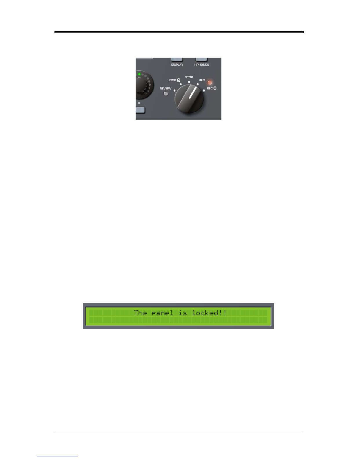
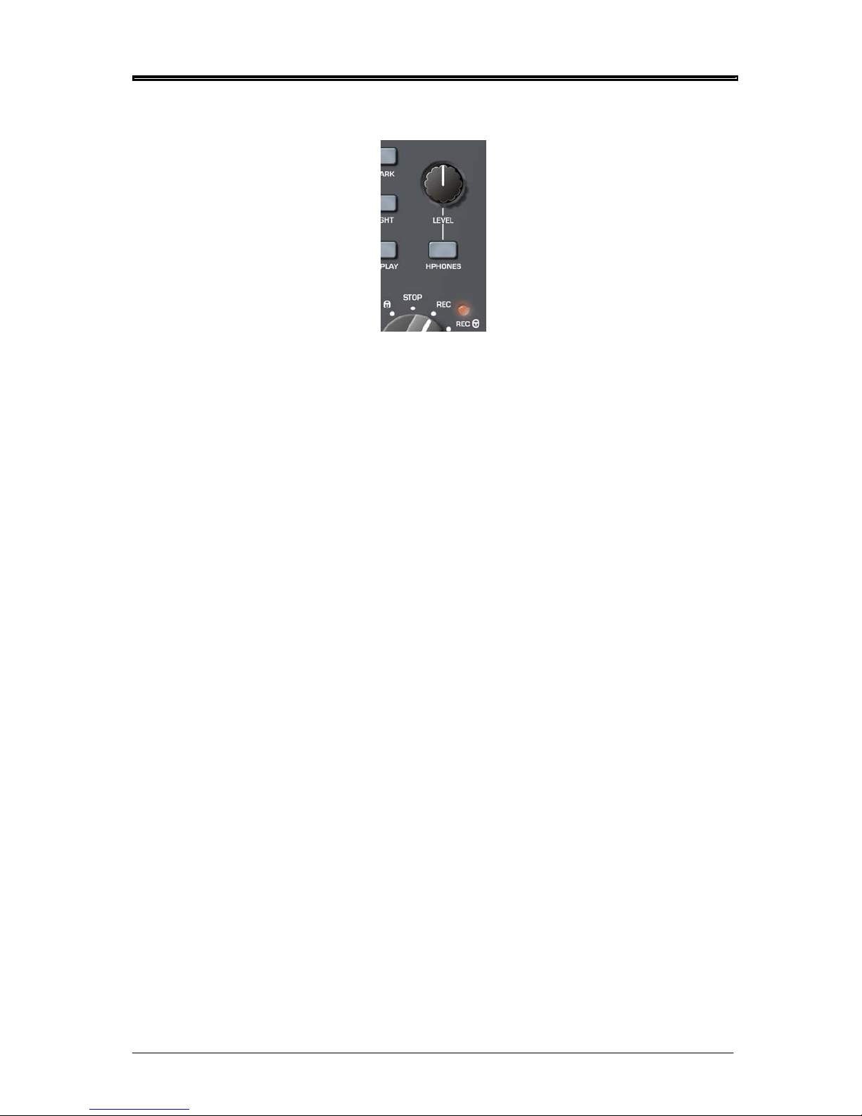
TRANSPORT CONTROL
The PORTADRIVE has a simple rotary switch to control transport. The five positions are:
STOP Stops playback or recording when the switch is turned to the 12-o-clock position. In
this condition, you can use the PORTADRIVE’s front panel without restriction.
STOP (lock) This stops playback or recording and also locks (or disables) the panel controls and
switches as a safety feature to prevent inadvertently adjusting anything.
You can choose what features are locked (or disabled) from the Panel Lock Mode,
accessed through the SETUP/MISC page on the top panel (see page104). The two
options are:
a) ALL - All controls are locked out
b) RESTRICTED - All controls are locked out apart from:-
INPUT LEVELS
BUSMIX LEVELS
SOLOS
H/P SHORTCUTS (hold ENABLE and press SOLO 1-6)
GROUP
MARK
LIGHT
DISPLAY pages 1&2
If you attempt to adjust or use any of the disabled controls, the LCD will briefly flash a
message to say that the panel is locked:
Page 22
FRONT PANEL
REC Puts the PORTADRIVE into record.
REC (lock) Puts the PORTADRIVE into record and also locks (or disables) the panel controls and
switches as a safety feature to prevent inadvertently adjusting anything by mistake
while you are recording.
You can choose what features are locked (or disabled) from the Panel Lock Mode,
accessed through the SETUP/MISC page on the top panel. The two options are:
a) ALL - All controls are locked out
b) RESTRICTED - All controls are locked out apart from:-
INPUT LEVELS
BUSMIX LEVELS
SOLOS
H/P SHORTCUTS (hold ENABLE and press SOLO 1-6)
GROUP
MARK
LIGHT
DISPLAY pages 1&2
If you attempt to adjust or use any of the disabled controls, the LCD will briefly flash a
message to say that the panel is locked (see previous page).
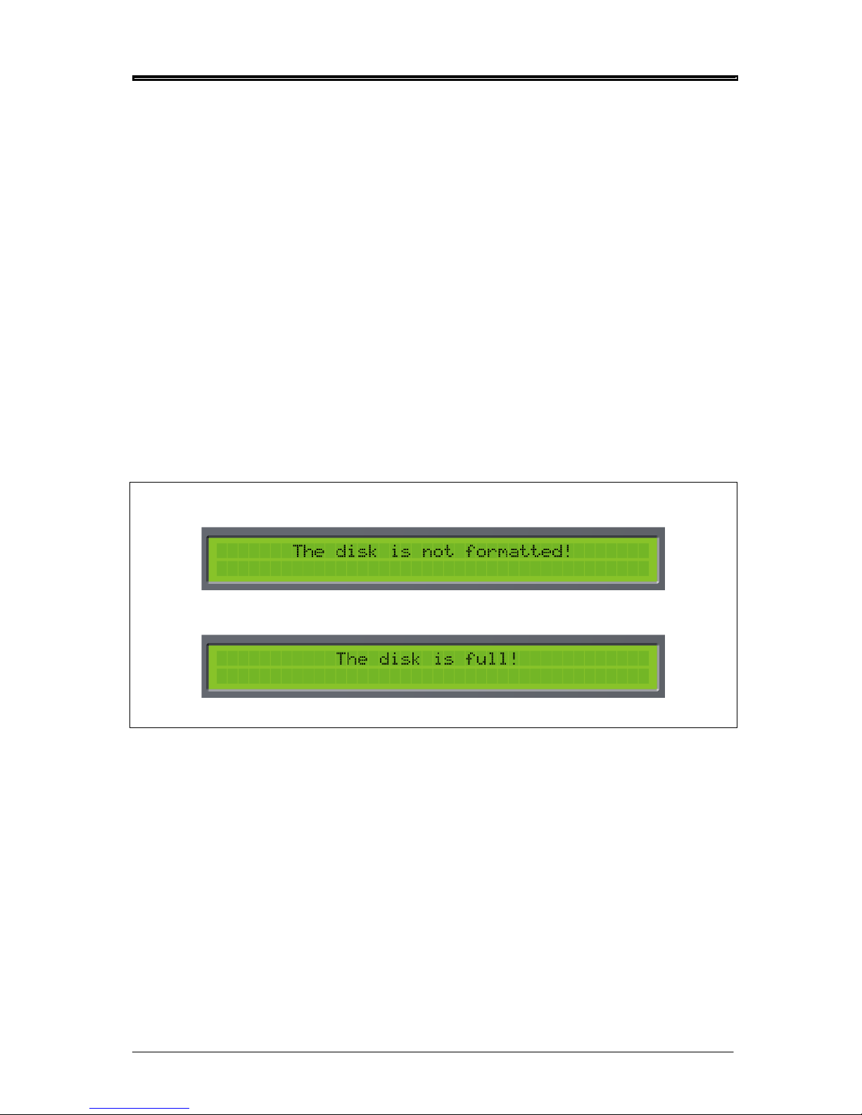
Note - If you put the PORTADRIVE into record and the disk is not formatted, the LCD will briefly
display an error message:
Similarly, if the disk is full (or close to full), you will be informed:
In either case, you should take the appropriate action to remedy the situation.
REVIEW This will play the most recently recorded take - ideal for checking what was just
recorded.
14 Version 1.31
Page 23
FRONT PANEL
Version 1.31 15
HEADPHONE CONTROL
The rotary control sets the level of the headphone output and the speaker on the top panel. It is a
‘push-lock’ control that can be pushed to recess it into the front panel to prevent accidental
adjustment.
The HPHONES key brings up the headphones menu in the LCD where you can set and select certain
options that relate to the headphones. See page 34.
Page 24
FRONT PANEL
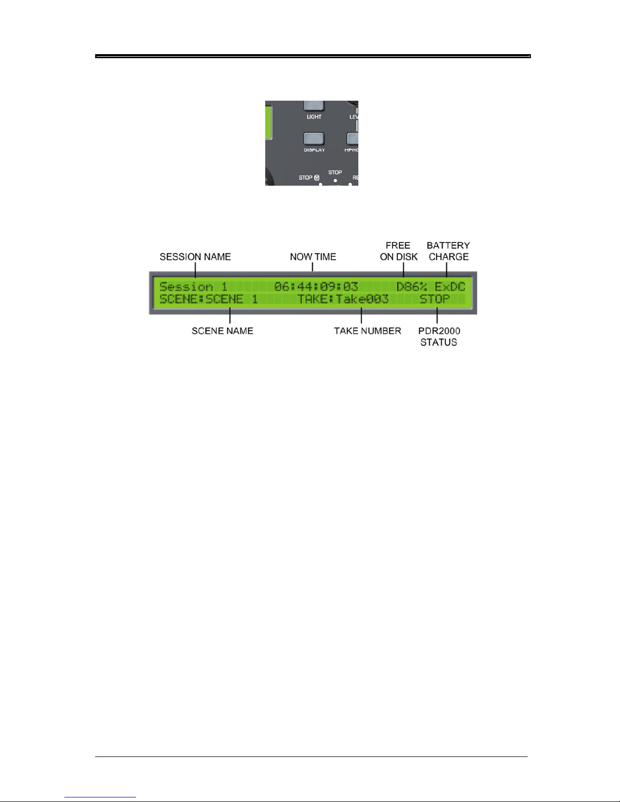
DISPLAY KEY
Pressing this key will display an overview of the current session on the LCD:
The fields are:
SESSION NAME Shows the currently selected session.
NOW TIME Shows the current timecode.
FREE ON DISK This shows the amount of free space on disk.
BATTERY CHARGE Shows the current battery charge and power source.
SCENE NAME Shows the current scene name.
TAKE NUMBER Shows the current take (recording).
PDR2000 STATUS Shows the PORTADRIVE’s current status (i.e. PLAY, REC, STOP).
16 Version 1.31
Page 25
FRONT PANEL
Version 1.31 17
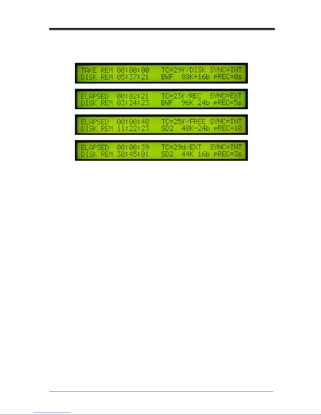
Pressing DISPLAY again will show further information about the current session including parameter
as well as time information:
Examples:
The fields are:
TAKE REM When the PORTADRIVE is playing back, this field shows TAKE REM (take remaining
time).
TC= frame rate / time-code mode
Frame rate: 23f, 24f, 25f, 29f, 29d, 30f, 30d
Time-code mode: REC=recrun, FREE=freerun, EXT=external, DISK=disktc
SYNC= INT or EXT
INT: Internal
EXT: External (wordclock, tri-level, video, digital audio)
DISK REM Shows the actual time that is free on disk for recording at the currently selected
sample rate, bit depth and number of enabled tracks.
BWF or SD2 Audio file format
FS; bits Sample rate and bit depth. ’+’ indicates 0.1% pull-up. ’-’ indicates 0.1% pull-down.
pREC= Pre-record buffer setting.
It is not possible to adjust or change anything in these screens - they are purely for information.
To cancel this display, press any other mode key.
Page 26
FRONT PANEL
LIGHT KEY
This turns the front panels’ LCD backlight on or off and can be used to conserve battery life.
If the LIGHT key is pressed for less than 1.0 seconds, the LCD backlight is only switched on for 10
seconds after which, it automatically turns off. If the LIGHT key is pressed for more than 1.0 seconds,
the LCD backlight is switched on permanently until such time as you press the LIGHT key again to
switch it off.
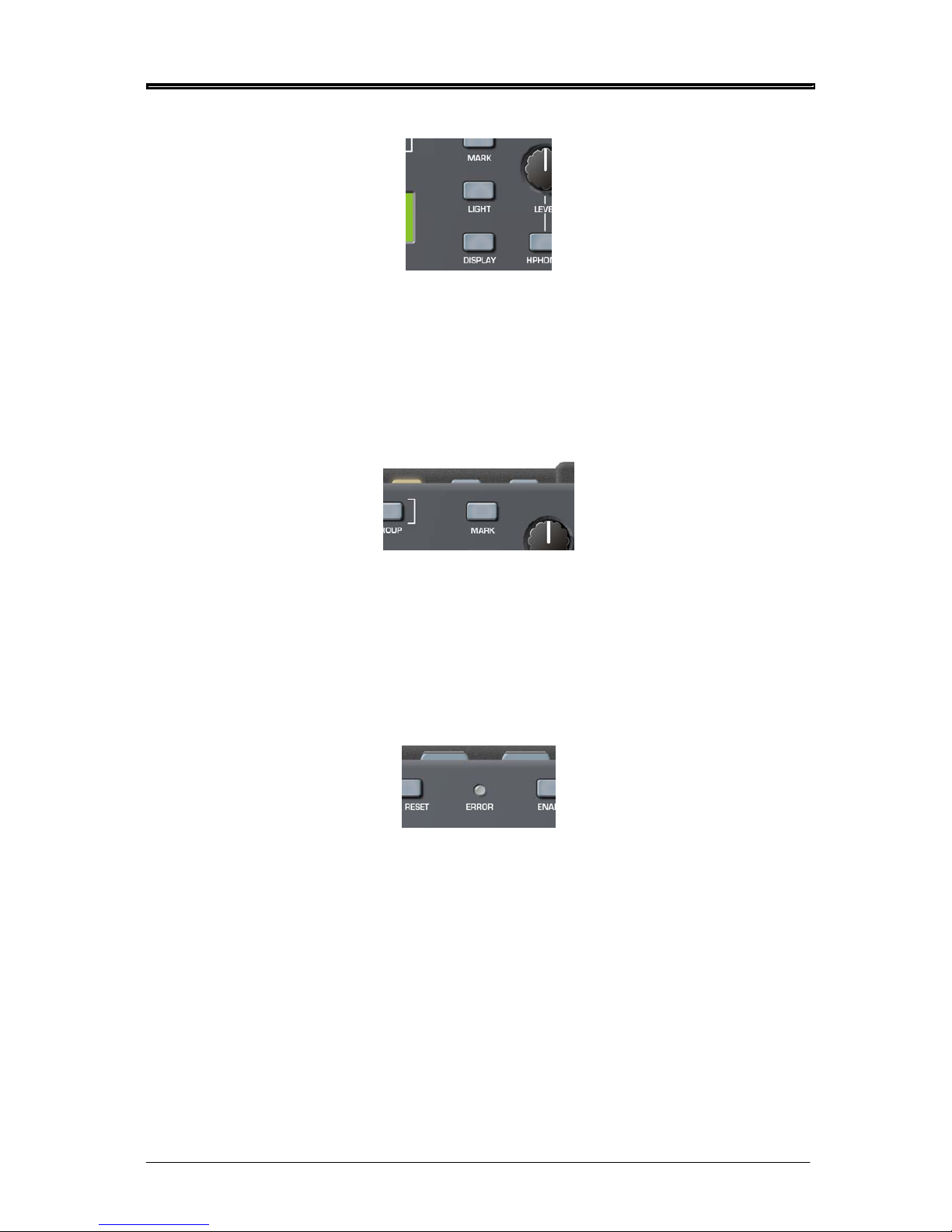
MARK KEY
The MARK key next to the headphone level control allows you to mark locate points.
When the mark key is pressed a ‘MARKER CREATED’ message is shown on the front and top LCDs.
Locate points can be marked on the fly during playback and/or recording simply by pressing the key at
the appropriate moment. Locate points can be recalled from the top panel’s LOCATE function, see
page 113.
ERROR LED
This three-coloured LED is used to give visible warnings and it will illuminate in one of the three
colours according to the condition being reported. These are:
BATTERY LOW Flashes red (you will also see an indication on the front and top LCDs).
DATA WRITE ERROR Constant red illumination for the duration of the error.
EXT TC ERROR Constant yellow illumination for the duration of the error.
EXT SYNC ERROR Constant green illumination for the duration of the error.
An audible error warning can also be set, see page 61.
18 Version 1.31
Page 27
FRONT PANEL
Version 1.31 19
UTILITY KEYS
This row of keys above the LCD gives access to several utilities you might need quick access to.
However, to prevent inadvertently pressing one of them by mistake, you need to press and hold the
ENABLE key and then press the required utility key. For example, to undo a recording, press and hold
ENABLE and UNDO.
The functions are:
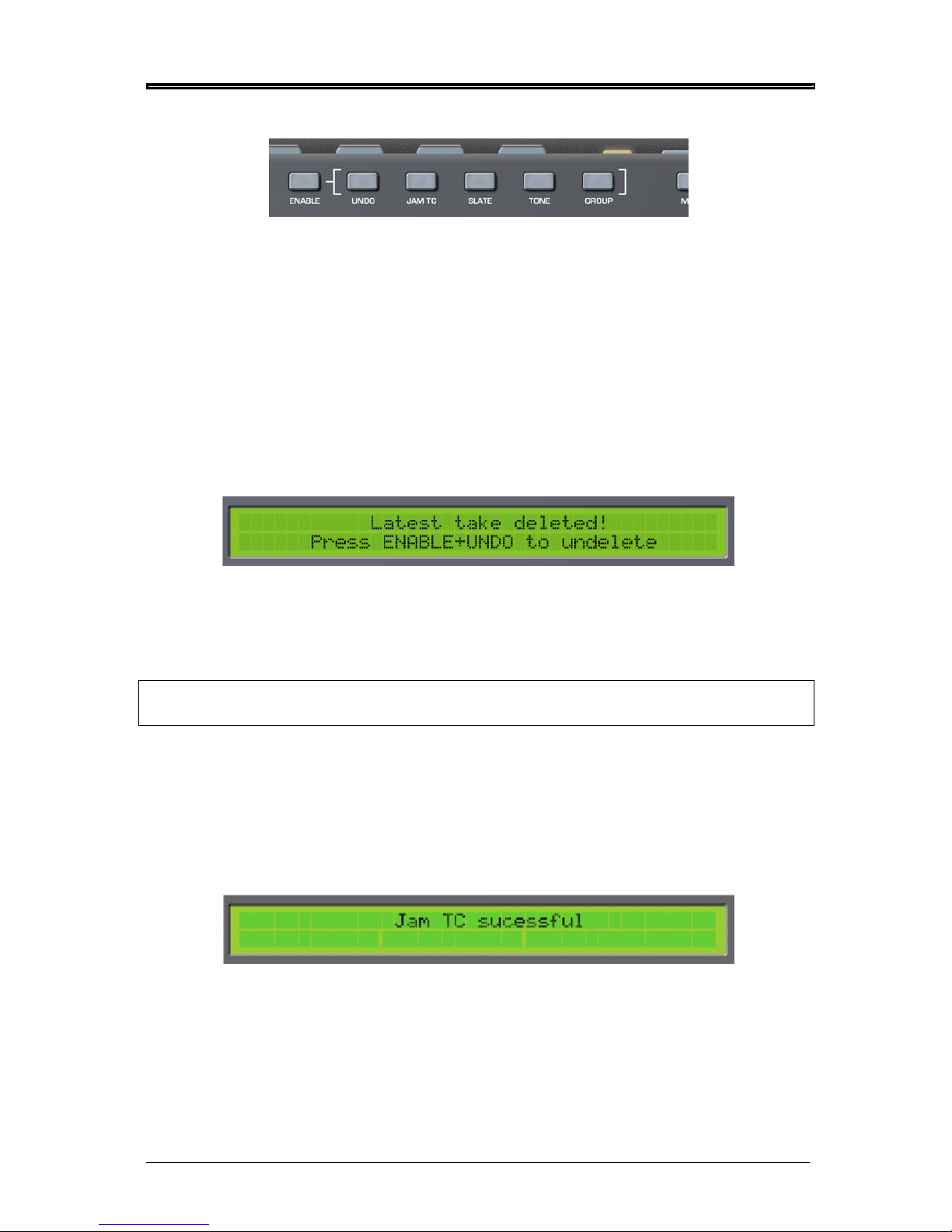
UNDO
Allows you to delete the latest recording (take) – all markers within the deleted take will also be
deleted. This is useful if there has been a false take, etc. - you can quickly undo (i.e. delete) it and rerecord it.
The LCD display will also show the following message for a few seconds
It is possible to undo this action if required by pressing and holding ENABLE and pressing UNDO
immediately after deleting the take. However, note that if you record immediately after deleting a take
in this way, it is not possible to undelete that take and the UNDO function will simply delete the new
recording.
Note - UNDO complies with the false-start convention whereby the new take uses the same
take number as the ‘false-start’ take.
JAM TC
JAM TC allows you to manually ‘jam’ the external timecode into the internal timecode generator. This
is only possible if there is a valid SMPTE LTC signal at the LEMO TC input and if the GEN TC is set to
FREERUN.
Press JAM whilst holding down the ENABLE key to initiate the jam function. The LCD display will
momentarily show the following message:
Page 28
FRONT PANEL
SLATE
The slate microphone mono signal will be output to wherever it has been routed in the SETUP/SLATE
page on the top panel (see page 99). Audio signals routed to the same destination(s) will be muted
during slate operation.
To activate the SLATE function, press and hold the ENABLE key and then press the SLATE key. The
SLATE key can be set to momentary, latching or ‘auto’ operation (where if the SLATE key is ‘dabbed’ i.e. pressed for a short period - SLATE operation is latched, or if pressed and ‘held’ for a second or
more, SLATE operation is momentary. This setting is made in the SETUP/SLATE page.
To de-activate the slate when in latching mode, simply press the SLATE key again
. The SLATE key
is illuminated when active. The SLATE can be routed to Tracks 1-6, stereo track and Main
and Aux L&R outputs.
TONE
This key allows you to generate a test tone. The test tone generator can be routed to Tracks 1-6,
stereo L/R tracks plus the main and Aux L/R outputs. Audio signals routed to the same destination(s)
will be muted whilst the tone generator is in use. The routing and the characteristics of the test tone
generator can be set in the SETUP pages (see page 98).
To activate the tone generator, press and hold the ENABLE key and then press the TONE key. The
TONE
key can be set to momentary, latching or ‘auto’ operation (where if the TONE key is ‘dabbed’ -
i.e. pressed for a short period - the tone generator is latched, or if pressed and ‘held’ for a second or
more, the tone generator’s operation is momentary. This setting is made in the SETUP/TONE page.
To de-activate the tone generator when in latching mode, simply press the TONE key again. The
TONE key is illuminated when active.
GROUP
The GROUP key is used to group all six rotary encoders so that levels 1-6 can be adjusted up or down
proportionally by the same amount using just one control. When the encoders are grouped, you only
need to turn one and all the others follow.
To enable the GROUP function, press and hold ENABLE and press GROUP - the key will illuminate.
The levels for the currently selected mode will now be grouped.
Of course, it could be that the LCD is not displaying the selected mode’s level parameters. This
doesn’t matter - when the mode’s LEVELS page is displayed on the LCD, the GROUP function will
have effect (it will have no effect on other sub-pages of any given mode). To de-activate GROUP for
the currently selected mode, press and hold ENABLE and press GROUP again.
INTERNAL MICROPHONE
The PORTADRIVE has an internal microphone that can be used for slating a recording. To use it,
simply press ENABLE +SLATE and speak into it! Note, however, that you will have to set up the track
routing for the slate mic. This is carried out in the top panel’s SETUP pages (see page 99).
That concludes our look at the main front panel functionality. In the next section we will look at some of
these in more detail.
20 Version 1.31
Page 29
FRONT PANEL MODES
Version 1.31 21
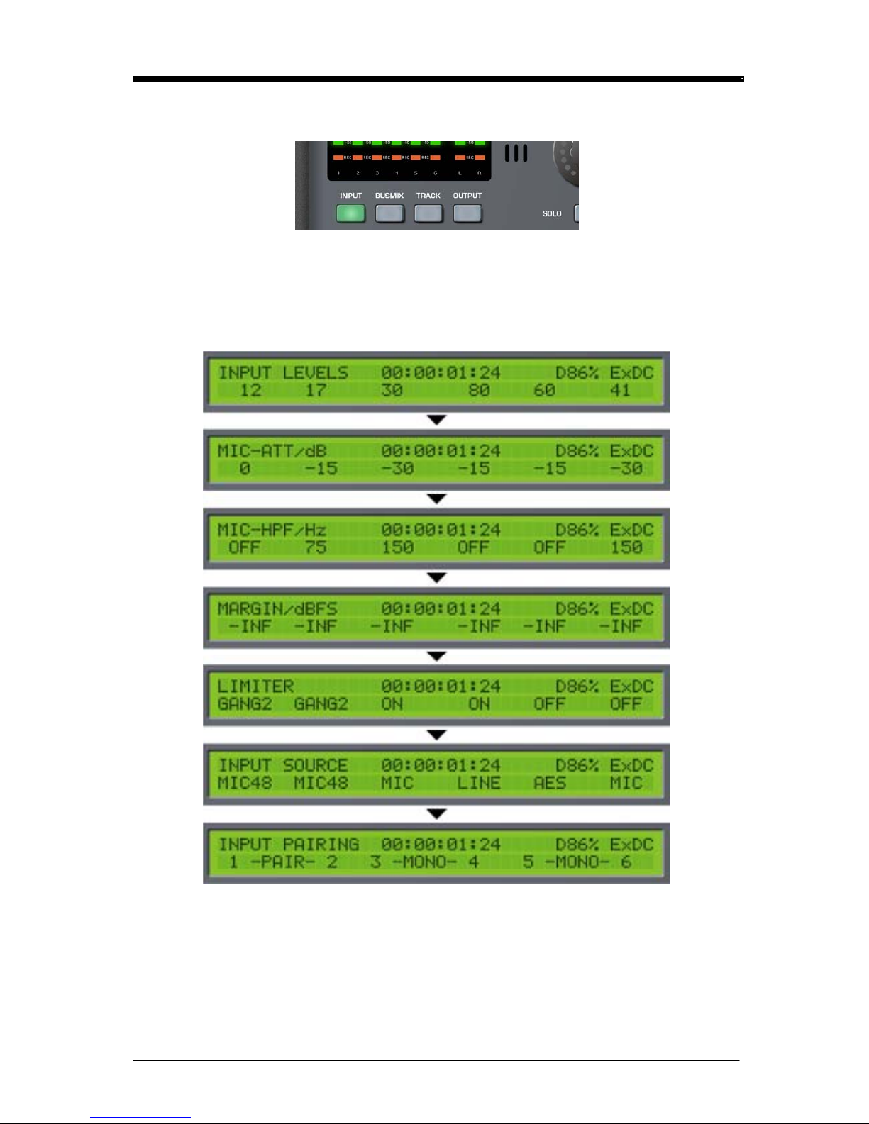
INPUT MODE
Pressing INPUT will cause the metering to show the level of the inputs. Headphone monitoring will
also, if selected to ‘FOLLOW METERS’, automatically switch to monitoring these signals. It will also
switch the LCD to show the input parameters. The first of these pages shows input level but by
repeatedly pressing the INPUTS
key, you can cycle through the various input parameters that are
available. The pages are as follows:
Pressing INPUT again will return you to the first of the pages (INPUT LEVELS).
The six rotary encoders are used to change the values of the parameters shown on the lower row of
the LCD. When setting LEVEL, the LEDs on the encoders’ ‘collars’ show the control’s position.
However, when setting other parameters (MIC ATT, MIC HPF, etc.) where the options are switched,
the LEDs around the encoders do not illuminate.
Page 30

FRONT PANEL MODES
22 Version 1.31
The parameters on the various pages are as follows:
INPUT LEVEL
The six encoders are used to adjust the input level. The range is 0-100 and it should be adjusted to
send as healthy a level of signal to disk as possible without overloading or distorting.
MIC ATT
Microphone attenuation can be set on each channel to 0 (no attenuation), -15dB and -30dB. Of
course, mic attenuation cannot be applied to digital or LINE inputs.
MIC HPF
This page allows you to apply a high pass filter to microphone inputs to filter out any unwanted low
frequency elements. Each channel’s filter can be set to OFF (no filter), 75Hz or 150Hz. The HPF
cannot be applied to digital or line input sources.
MARGIN
You can use this page to monitor the peak levels (in dBFS) of the inputs. This page is provided simply
for information - no parameters can be changed. However, when PEAK RESET key is pressed, the
display is re-initialised.
LIMITER
The channel limiters can be switched on and off in this page. However, it also possible to ‘gang’ pairs
of limiters on adjacent channels, or all six channels. The full range of options are OFF, ON, GANG 2
(Adjacent channels are ganged) and GANG 6 (all six input limiters are ganged).
In the case of the ‘ganged’ selection, when one channel has this selection, its adjacent channel is
automatically ganged to its neighbour. For example, in the case of selecting this option on Channel 1,
Channel 2 will automatically be ganged; in the case of selecting this option for Channel 4, Channel 3
will automatically be ganged. It is recommended that stereo-paired channels use the ‘ganged’
selection.
The limiters can only be applied to mic or line signal sources.
INPUT SOURCE
You may select the input source for each channel in this page. The options are:
INPUT 1 LINE, MIC, SPDIF, AES, OFF, MIC48
INPUT 2 LINE, MIC, SPDIF, AES, OFF, MIC48
INPUT 3 LINE, MIC, AES, OFF, MIC48
INPUT 4 LINE, MIC, AES, OFF, MIC48
INPUT 5 LINE, MIC, AES, OFF, MIC48
INPUT 6 LINE, MIC, AES, OFF, MIC48
• The MIC selection is a normal microphone input through the balanced XLR’s.
• MIC48 is a microphone input through the balanced XLR’s but with 48V phantom power
applied.
• LINE selects a line level input through the balanced XLR’s
• SPDIF (Input channels 1 and 2 only) select an SPDIF digital audio input through the
SPDIF phono connector.
• AES selects an AES/EBU digital audio input signal through the multi-channel D-Sub
connector.
Note –
When inputs 1&2 are both set to OFF, the associated input circuitry is also turned off thus saving
power. Similarly pairs 3&4, 5&6 operate in the same manner.
Page 31

FRONT PANEL MODES
Version 1.31 23
INPUT PAIRING
Adjacent inputs (e.g. 1+2, 3+4, 5+6) can be ‘paired’ so that either encoder associated with those
channels can be used to adjust their levels proportionally. Primarily, this is useful when using stereo
signals. However, you may well find other uses for it. If there is an offset between the two channels’
levels, this offset is retained as either encoder is adjusted.
IMPORTANT NOTE REGARDING INPUT PAIRING
LEVELS
When two channels are paired and their levels are offset, the offset is retained even when the upper
limits of either channel’s range is reached. For example....
Two channels are paired. Channel 1 has a level of 80, Channel 2 has a level of 90.
You adjust Channel 1’s encoder, increasing the level. The two channels increment in parallel:
80/90... 80/91... 82/92... 83/93.. 84/94... etc.
Until you reach 90/100
You can continue to increase Channel 1:
91/100... 92/100... 93/100... 94/100... 95/100... etc.
Until you reach 100/100
However, if you now turn Channel 1 down, you will see the following:
99/100... 98/100... 97/100... 96/100... 95/100... etc.
Until you reach 90/100.
If you now continue to decrease Channel 1’s level, the two channels will continue to track in parallel
with the original offset remembered:
89/99... 88/98... 87/97... 86/96... 85/95... etc.
Until you are back to the original setting of 80/90.
If you continue to decrease Channel 1, you will see the following:
79/89... 78/88... 77/87... 76/86... 75/85... etc.
However, using this example, things would be different if you were adjusting Channel 2’s encoder. In
this case, when you reach Channel 2’s extreme (i.e. 100), no further changes would take place on
Channel 1 because you’ve gone as far as you can with the encoder you are adjusting.
NOTE: The following also applies to BUS INPUT PAIRING, BUS OUT LEVELS and in fact any page
where levels can be paired such as the GROUP function.
Page 32

FRONT PANEL MODES
BUSMIX MODE
Pressing BUSMIX will cause the metering to show the level of the bus mixer’s inputs. If ‘FOLLOW
METERS’ mode is selected, headphone monitoring will also automatically switch to monitoring these
signals. It will also switch the LCD to show the busmix parameters. The first of these pages shows the
mixer’s input level but by repeatedly pressing the BUSMIX
key, you can cycle through the various
parameters that are available. The pages are as follows:
Pressing BUSMIX again will return you to the first of the pages (BUSMIX INPUT LEVELS).
As we saw with the INPUTS mode, the six rotary encoders are used to change the values of the
parameters shown on the lower row of the LCD. When setting variable parameters such as LEVEL
and PAN, the LEDs on the encoders’ ‘collars’ show the control’s position. However, when setting
other parameters (M/S DECODE, for example) where the options are switched, the LEDs around the
encoders do not illuminate.
The bus-mixer is ideal for recording each of the 6 inputs to its own track as well as a stereo mix of
those inputs to a further two disk tracks. In other words, INPUTS 1-6 go to TRACKS 1-6 respectively
and BUSMIX LR goes to TRACKS 7-8.
Each adjacent pair of channels also has an MS decoder, which is individually switchable.
24 Version 1.31
Page 33

FRONT PANEL MODES
Version 1.31 25
The parameters on the various pages are as follows:
BUS-MIXER INPUT LEVELS
Here you can set the bus mixer’s input levels.
Because the input signal is fed from after the inputs’ level controls, with all the BUSMIX level controls
set to the same value, the mix is effectively a copy of the inputs’ level; settings. However, by adjusting
the bus mixer’s level controls, a sub-mix can be set up which can be recorded to the stereo L/R tracks.
BUS-MIXER INPUT PANS
Using the six rotary encoders, you can set the pan position of the bus mixer’s inputs. With these, you
can set up a stereo sub mix with each input placed in the stereo image as required.
BUS OUT LEVELS
Here, you may adjust the overall output level of the bus mixer’s stereo output. Encoders 1 and 6 are
used to set the left and right levels respectively (encoders 2 and 5 are de-activated in this page).
Encoders 3 or 4 can be used to pair the L/R output channels’ level. When paired, you can use either
encoder 1 or 6 to set the master output level of the bus mixer’s stereo output.
BUS-MIXER INPUT PAIRING
Adjacent channels (e.g. 1+2, 3+4, 5+6) can be ‘paired’ and either encoder associated with those
channels can be used to adjust their levels proportionally. Primarily, this is useful when using stereo
signals. However, you may well find other uses for it. If there is an offset between the two channels’
levels, this offset is retained as either encoder is adjusted.
BUS-MIXER INPUT MS-DECODE
The encoders can be used to switch MS decoding on or off for adjacent pairs of channels. This is
particularly useful if, for example, an MS stereo mic is being used on inputs 1/2 and is being recorded
directly to tracks 1/2 un-decoded but it is necessary to provide an L/R stereo mix of these using the
bus mixer.
Page 34

FRONT PANEL MODES
TRACK MODE
Pressing TRACK will cause the metering to show the level of the audio coming off the disk tracks
1
. If
‘FOLLOW METERS’ mode is selected, headphone monitoring will also automatically switch to
monitoring a mix of tracks 1-6. It will also switch the LCD to show the disk tracks parameters. By
repeatedly pressing the TRACK
key, you can cycle through the various parameters that are available.
The pages are as follows:
Pressing TRACK again will return you to the first of the pages.
1 Only when the PDR2000 is playing back. When the PDR2000 is recording or stopped (i.e. not playing
back), the meters will show the level of the inputs to the disk tracks.
26 Version 1.31
Page 35

FRONT PANEL MODES
Version 1.31 27
TRACKS 1-6 SOURCE / ARM
This page is used to select an input source for the disk tracks. By default, they are inputs 1-6 but these
may be changed according to requirements. Any combination of tracks may armed for each take. The
input sources are:
Track 1: INP1 (*) BUS L OUTL OFF
Track 2: INP2 (*) BUS R OUTR OFF
Track 3: INP3 (*) BUS L OUTL OFF
Track 4: INP4 (*) BUS R OUTR OFF
Track 5: INP5 (*) BUS L OUTL OFF
Track 6: INP6 (*) BUS R OUTR OFF
(*) The actual input source for these selections depend on what is set as the input source in the INPUT
mode (e.g. MIC, MIC48, AES, etc.).
Note: When a track source is set to OFF, it is effectively disarmed - that is, it is not recorded. The
track arm indicators below the metering indicate which tracks are currently armed.
It is not possible to change a track source when the PORTADRIVE is actually recording. If you attempt
this, you will be prompted on the LCD accordingly:
Track Arming notes when using BWF formats.
BWFm
There are no limitations. Any number or combination of tracks can be armed for each take in a
session. For example, take 1 could have all 8 tracks armed, take 2 could have just tracks 2,5
and 7 armed and take 3 could have tracks 1,2,4,5,8 armed etc.
BWFp
If you set a group of tracks to polyphonic for a session, then it is not possible to individually
arm/disarm the tracks within that polyphonic group between each take. It is only possible to
arm/disarm the whole group between each take. The main reason for this is to ensure that the
original track number is maintained when importing into a current AVID system.
For further details explaining BWFm and BWFp file formats see page 90.
A few examples:-
If you set TRACKS 1-X to 6 X POLY, then tracks 1-6 will all be armed if any one of the tracks 1-6 is
armed. Only if you disarm (turn off) all tracks 1-6, then all tracks 1-6 will be disarmed.
If you set TRACKS 7&8 to 2 X POLY, then tracks 7&8 will both be armed if either one them is armed.
Only if you disarm (turn off) both tracks 7&8, then both of them will be disarmed.
If you set TRACKS 1-X to MONO and TRACKS 7&8 to 2 X POLY, then you will be able to individually
arm/disarm any of the tracks 1-6 between each take without limitation. Tracks 7&8 will both be armed if
either one of them is armed. Only if you disarm (turn off) both tracks 7&8, then both of them will be
disarmed.
Reminder: Tracks are armed or disarmed in the front or top panel TRACK menu.
Page 36

FRONT PANEL MODES
28 Version 1.31
TRACK INPUT MS-DECODE
You can use the rotary encoders to select whether a pair of adjacent tracks is routed through an MS
Decoder or not. This is particularly useful for decoding an MS pair so that it is recorded to disk as a
L/R pair.
TRACKS L-R SOURCE ARM
Encoders 1 and 2 are used to set the input source for the L/R tracks. The options are:
Left: INP7 BUSL OUTL OFF
Right: INP8 BUSR OUTR OFF
The default assignment is OFF. When any of the inputs are selected, these tracks are enabled for
record.
TRACKS 1-6 MARGIN/dBFS
You can use this page to monitor the peak levels (in dBFS) of the tracks.
In record and stop, the display shows disk track input level peaks. When playing back, the display
shows track output levels.
This page is provided simply for information - no parameters can be changed. However, when PEAK
RESET key is pressed, the display is re-initialised.
Page 37

FRONT PANEL MODES
Version 1.31 29
OUTPUT MODE
Pressing OUTPUT will cause the metering to show the level of the MAIN L/R outputs on the L/R
columns of the meters and the LCD will show the first of the OUTPUT pages. The headphones will
monitor the main L/R output if ‘FOLLOW METERS’ mode is selected. However, what is shown in the
meters and what is heard through the headphones depends on the page being displayed. The pages
are as follows:
Encoders 1 and 2 can be used to select the MAIN outputs’ input source. The source options are:
BUS L/R The L/R outputs of the BUS MIXER
OUT L/R The L/R outputs of the OUTPUT mixer
INP 1/2 Inputs 1 and 2
INP 3/4 Inputs 3 and 4
INP 5/6 Inputs 5 and 6
INP 7/8 Inputs 7 and 8
2CH RET The 2-Channel return
TRACKS 1/2 Tracks 1 and 2
TRACKS 3/4 Tracks 3 and 4
TRACKS 5/6 Tracks 5 and 6
TRACKS L/R Whatever is being (or has been) recorded to the L/R tracks
OFF (*)
TONE and SLATE can also be routed to the MAIN output. This is set in the top panel SETUP window.
See pages 98 and 99 respectively.
(*) When both the MAIN and AUX input sources’ are set to OFF, the output path electronics are turned
off thus saving power. As such, if you are not using both the MAIN and AUX outputs, switching both
sources to OFF will conserve battery life.
Encoders 3 or 4 can be used to switch MS decoding on or off. This can be useful if, for example,
inputs 1 and 2 are an MS pair of microphones and it is necessary to feed an MS decoded signal
through the MAIN outputs.
Encoders 5 and 6 can be used to set the master level for the MAIN outputs.
When this page is displayed, the meters show the MAIN output level in the L/R columns and if
‘FOLLOW METERS’ mode is selected, the headphones carry a copy of the MAIN outputs.
Page 38

FRONT PANEL MODES
Pressing the OUTPUT key again will show this screen:
Here you can set the AUX outputs’ input source, enable or disable MS decoding and set the master
level. The options are exactly the same as for the MAIN outputs.
(*) When both the MAIN and AUX input sources’ are set to OFF, the output path electronics are turned
off thus saving power. As such, if you are not using both the MAIN and AUX outputs, switching both
sources to OFF will conserve battery life.
When this page is displayed, the meters show the AUX output level in the L/R columns and if
‘FOLLOW METERS’ mode is selected, the headphones carry a copy of the AUX outputs.
Pressing the OUTPUT key again will show this screen:
It is possible to select INPUTS, TRACKS or OFF as the input source for the output mixer - if either
INPUTS or TRACKS are selected, further functions are available on extra pages as follows.
When INPUTS is selected as the output mixer’s source, the following screens are available:
30 Version 1.31
Page 39

FRONT PANEL MODES
Version 1.31 31
When INPUTS is selected as the output mixer’s source, you can use the output mixer to set up an
alternative mix to BUSMIX. This might be used to provide a special mix feed to a director or external
recording device. If you have routed inputs 1-6 to disk tracks 1-6, these will not be affected by
adjusting the output mixer:
LEVEL
LEVEL
LEVEL
LEVEL
LEVEL
LEVEL
OUTPUT MIXER
DISK
RECORDING
CORE
LEVEL
LEVEL
LEVEL
LEVEL
LEVEL
LEVEL
INPUTS
TRACK
ARM
The parameters on the various pages are as follows:
OUTPUT-MIXER INPUT LEVELS
Here you can set the output mixer’s input levels. Because the input signal is fed from after the input
level controls, with all the OUTMIX level controls set to the same value, the mix is effectively a copy of
the input level settings. However, by adjusting the output mixer’s level controls, an alternative sub-mix
can be set up which can be recorded to the stereo L/R tracks or routed to the outputs.
OUTPUT-MIXER INPUT PANS
Using the six rotary encoders, you can set the pan position of the output mixer’s inputs. With these,
you can set up a stereo sub mix with each input placed in the stereo image as required.
OUTPUT-MIXER L&R LEVELS
Here, you may adjust the overall output level of the output mixer’s stereo output. Encoders 1 and 6 are
used to set the left and right levels respectively (encoders 2 and 5 are de-activated in this page).
Encoders 3 or 4 can be used to pair the L/R output channels’ level. When paired, you can use either
encoder 2 or 5 to set the master output level of the output mixer’s stereo output.
OUTPUT-MIXER INPUT PAIRING
Adjacent channels (e.g. 1+2, 3+4, 5+6) can be ‘paired’ and either encoder associated with those
channels can be used to adjust their levels proportionally. Primarily, this is useful when using stereo
signals. However, you may well find other uses for it. If there is an offset between the two channels’
levels, this offset is retained as either encoder is adjusted.
OUTPUT-MIXER INPUT MS-DECODE
The encoders can be used to switch MS decoding on or off for adjacent pairs of channels. This is
particularly useful if, for example, an MS stereo mic is being used on inputs 1/2 and are being
recorded directly to tracks 1/2 un-decoded but it is necessary to provide a stereo mix of these using
the output mixer.
Page 40

FRONT PANEL MODES
When, in the MIXER SOURCE page, the input source is set to TRACKS, the following extra pages are
available:
When TRACKS is selected as the output mixer’s source, the output mixer can be used to provide an
alternative stereo or mono mix of what’s playing back off disk or being recorded to disk. Levels going
to disk are unaffected (these are set in the INPUT mode) but the output mixer can be used (for
example) to provide an alternative director’s monitoring feed or as a feed to an external recording
device. This mix can also be routed to the tracks L & R on the disk for sub-mixing.
LEVEL
LEVEL
LEVEL
LEVEL
LEVEL
LEVEL
OUTPUT MIXER
DISK
RECORDING
CORE
LEVEL
LEVEL
LEVEL
LEVEL
LEVEL
LEVEL
INPUTS
TRACK
ARM
32 Version 1.31
Page 41

FRONT PANEL MODES
Version 1.31 33
The parameters on the various pages are as follows:
OUTPUT-MIXER TRACK LEVELS
Here you can set the output mixer’s input levels.
OUTPUT-MIXER TRACK PANS
Using the six rotary encoders, you can set the pan position of the output mixer’s inputs. With these,
you can set up a stereo sub mix with each input placed in the stereo image as required.
OUTPUT-MIXER L&R LEVELS
Here, you may adjust the overall output level of the output mixer’s stereo output. Encoders 1 and 6 are
used to set the left and right levels respectively (encoders 2 and 5 are de-activated in this page).
Encoders 3 or 4 can be used to pair the L/R output channels’ level. When paired, you can use either
encoder 2 or 5 to set the master output level of the output mixer’s stereo output.
OUTPUT-MIXER TRACK PAIRING
Adjacent channels (e.g. 1+2, 3+4, 5+6) can be ‘paired’ and either encoder associated with those
channels can be used to adjust their levels proportionally. Primarily, this is useful when using stereo
signals. However, you may well find other uses for it. If there is an offset between the two channels’
levels, this offset is retained as either encoder is adjusted.
OUTPUT-MIXER TRACK MS-DECODE
The encoders can be used to switch MS decoding on or off for adjacent pairs of channels. This is
particularly useful if, for example, an MS stereo mic is being used on inputs 1&2 and is being recorded
directly to tracks 1&2 un-decoded but it is necessary to provide a stereo mix of these using the output
mixer.
Page 42

FRONT PANEL MODES
HEADPHONE SETUP MODE
Pressing the HEADPHONE key allows you to set certain parameters that relate to the headphones.
HEADPHONE CONFIGURATION PRESETS
On the PORTADRIVE, it is possible to store and recall six preset monitoring configurations. This
feature allows you to quickly select different signal sources in the headphone monitoring for checking
signals, confidence monitoring etc. The presets only affect monitoring and do not affect signals being
recorded to disk.
Pressing the HEADPHONES key shows this screen on the LCD:
Encoder 1 can be used to select any of the six presets simply by rotating it.
You can also select presets directly by pressing and holding ENABLE and then pressing any one of
the six SOLO keys. When a preset is selected by the ENABLE+SOLO method, the LCD will briefly
show the PHONES PRESET page for that preset.
Press ENABLE+SOLO1 to select H/P Preset User 1
Press ENABLE+SOLO2 to select H/P Preset User 2
Press ENABLE+SOLO3 to select H/P Preset User 3
Press ENABLE+SOLO4 to select H/P Preset User 4
Press ENABLE+SOLO5 to select H/P Preset User 5
Press ENABLE+SOLO6 to select H/P Preset User 6
Encoders3 and 4 can be used to select the headphone-monitoring source. The source options are:
BUSMIX L&R L/R outputs of the bus mixer
OUTMIX L&R L/R outputs of the output mixer
MAIN OUT Duplication of the MAIN L/R outputs
AUX OUT Duplication of the AUX L/R outputs
INP1/2 Inputs 1 and 2
INP3/4 Inputs 3 and 4
INP5/6 Inputs 5 and 6
INP7/8 Inputs 7 and 8
2CH RETURN The 2-Channel return
TRK1/2 Tracks 1 and 2
TRK3/4 Tracks 3 and 4
TRK5/6 Tracks 5 and 6
TRKL/R Tracks L and R
FOLLOW METERS See following explanation.
With the ‘FOLLOW METERS’ option selected, the source will be the currently selected mode (i.e.
INPUTS, BUSMIX, TRACKS, OUTPUT). in this way, the headphone (and top speaker) monitoring will
34 Version 1.31
Page 43

FRONT PANEL MODES
Version 1.31 35
follow the metering so that what you’re seeing on the meters is what you’re hearing in your
headphones. However, by pressing HEADPHONES and using Encoder 1, you can quickly override
this to monitor any signal within the PORTADRIVE.
Encoders 5 and 6 can be used to select a decode option for the preset. The options are STEREO,
MONO BOTH, MONO R, MONO L and MS
Also, when the source is set to FOLLOW, you actually have access to independent sub-mixers that
allow you set your own personal headphone mix.
If you press the HEADPHONES key when in INPUT mode, the following extra pages are available:
With these pages, you can create an independent, alternative headphone mix of the inputs.
LEVEL
LEVEL
LEVEL
LEVEL
LEVEL
LEVEL
H/P MIXER
DISK
RECORDING
CORE
LEVEL
LEVEL
LEVEL
LEVEL
LEVEL
LEVEL
INPUTS
TRACK
ARM
Settings made here will not affect signals being recorded to disk, only those being heard in the
headphones (or through the top panel speaker). The parameters and functions are exactly the same
as we have seen in the OUTPUT mixer mode. Please refer to page 31 for details.
Page 44

FRONT PANEL MODES
If you press the HEADPHONES key when in TRACK mode, the following extra pages are available:
With these pages, you can create an independent and alternative headphone mix for the audio going
to disk during record or coming off disk during playback.
LEVEL
LEVEL
LEVEL
LEVEL
LEVEL
LEVEL
HEADPHONE MIX IN 'TRACKS' MODE
H/P MIXER
DISK
RECORDING
CORE
LEVEL
LEVEL
LEVEL
LEVEL
LEVEL
LEVEL
INPUTS
TRACK
ARM
Settings made here will not affect signals being recorded to disk, only those being heard in the
headphones (or through the top panel speaker). The parameters and functions are exactly the same
as we have seen in the OUTPUT mixer mode. Please refer to page 31 for details.
Using these headphone sub-mixers in conjunction with all the other mixers contained within the
PORTADRIVE adds a lot of flexibility to the unit and you could, for example, have a certain mix going
to disk, another mix going out through the MAIN and/or AUX L/R outputs, another mix going to the L/R
tracks (via BUSMIX) and separate mixes for inputs and tracks in your headphone/speaker monitoring.
Headphone presets are automatically updated and saved whenever any changes are made.
36 Version 1.31
Page 45

FRONT PANEL MODES
Version 1.31 37
MANAGING METADATA
The PORTADRIVE allows front panel as well as top panel editing of metadata (SLATE, TAKE and
NOTES).
It is possible to edit any take’s SLATE name either before or after it has been recorded.
It is possible to edit a take’s NOTES at any time, before, after or even during recording.
It is possible to record the next TAKE into a previously created SLATE.
PORTADRIVE provides a 'universal' system that allows the user to work with both the USA and UK
naming conventions, or in fact whatever naming system they wish.
Note - A PS2 keyboard can be used to enter text when operating from the front or top panels,
but not both at the same time.
Description of types of Metadata
SLATE – This is the name of the slate or scene (or whatever you want to use it for) up to a maximum
of 12 characters.
Examples:
• ‘270’, ‘270 A’, ‘270 B’ . . . . . ‘270 Z’, ‘270 AA’, ‘270 AB’ etc [US convention]
• ‘001’, ’002’, ‘003’ etc [UK convention]
• ‘270WT’ [Wild track]
• ‘Movement’, ‘Song title’, etc [any name]
TAKE – This is a 3-digit number ranging from 001 – 999. This number is automatically controlled by
PORTADRIVE as follows:-
• TAKE number increments by 1 each time record is instigated.
• TAKE number automatically resets to ‘001’ if a new SLATE is created.
• If the next take to be recorded is in a previously created SLATE, then the TAKE number of
the next take will be equal to the last take number in that slate + 1. So, if there were three
takes in slate 001, the next take would automatically be take 004 in slate 001.
• If a take was recorded into the wrong slate (i.e. with the wrong slate name), then it is
possible to edit its slate name i.e. move it to another slate. If the take is moved to a new
slate, then its take number will default to ‘001’.
• If the take is moved to an existing slate, then its take number will default to the last take
number in that slate +1.
NOTES – This is a text string up to a maximum of 50 characters, which the user can use to make any
comments about a particular take.
Metadata uses
SLATE name, TAKE number and NOTES are stored in the description field of the Broadcast wave
header and can be read by most professional applications including later versions of AVID.
SLATE name and TAKE number also form the structure of the PORTADRIVE audio file name.
Example based on take 3 of slate 123a from session (roll) 115
115s123a_T003_4.wav refers to track 4, monophonic BWF
Page 46

FRONT PANEL MODES
Front Panel Editing.
Editing of metadata is performed in the EDIT INFO page accessed by holding the DISPLAY button for
more than 1 second.
As can be seen from above EDIT INFO page, the bottom row of the front panel LCD shows the
currently selected take. The above example shows we have selected take 4 (which happens to be the
next take to be recorded) of slate B270AA.
To return to DISPLAY page 1, press the DISPLAY button.
RECORDING THE NEXT TAKE INTO AN EXISTING SLATE
In the EDIT INFO page, use rotary encoder 2 to select an existing slate. If you want to know what the
take number of the next recording will be, use rotary encoder 4 to select the take number that is
followed by ‘[NEXT]’. This displays the next take number.
Instigate RECORD by using the transport controls. The take will be recorded into the selected slate.
38 Version 1.31
Page 47

FRONT PANEL MODES
Version 1.31 39
RECORDING THE NEXT TAKE INTO A NEW SLATE
In the EDIT INFO page, use rotary encoder 4 to select the take number that is followed by ’[NEXT]’.
In the example above, the next take to be recorded is take 4 of slate B270AA.
Press SOLO2 to access the SLATE EDIT page
Let’s assume that we want to change the next take to be recorded from B270AA, take 4 to B270AB,
take 1.
Rotate rotary encoder 1 (SHIFT) to shift the cursor to the position of the character you want to change.
Rotate clockwise to shift right and anti-clockwise to shift left.
The default starting position of the cursor is always the right-most character as it is this one that is
most frequently going to be changed.
Rotate rotary encoder 2 (CHARA) to change the character in the selected cursor position. In this
example, rotate it 1 step clockwise to change from ‘A’ to ‘B’.
If you need to enter a number, rotary encoder 3 (<0-9>) can be used as a shortcut to numeric
characters. Also, if necessary, use SOLO4 to delete a character.
Press SOLO6 to SAVE. The LCD will save and return to the EDIT INFO page which will now display
the edited take i.e. SLATE: B270AB TAKE:001[NEXT].
Instigating record will make take 001 of slate B270AB current and so the [NEXT] indicator will vanish.
Note - If you make a mistake in your edit, you can ABORT using the SOLO5 button – in this
case the LCD will return to the EDIT INFO page without saving any changes.
Page 48

FRONT PANEL MODES
MOVING A RECORDED TAKE TO A DIFFERENT SLATE (EXISTING OR NEW)
In the EDIT INFO page, select the SLATE name and TAKE number of the take that you want to move
(edit) using rotary encoders 2 and 4 respectively.
Press SOLO2 to enter the slate EDIT page.
Enter a new slate name or name of an existing slate and then press SOLO6 to SAVE and return to the
EDIT INFO page or press SOLO5 to ABORT the edit and return to the EDIT INFO page.
If SAVE (SOLO6) is pressed, the message ‘Take moved’ appears briefly in the LCD.
Note - When you move a take to another slate, its new take number will be the last take
number in that slate + 1. For example, if you move a take to a slate that already has takes 001,
002 and 003
,
then the moved take will become 004 in that slate.
ENTERING NOTES FOR A TAKE (BEFORE, DURING OR AFTER RECORDING)
In the EDIT INFO page, select the SLATE name and TAKE number of the take that you want to
add/edit notes to, using rotary encoders 2 and 4 respectively.
Press SOLO6 to enter the take NOTES EDIT page.
Enter a maximum of 50 characters and then press SOLO6 to SAVE and return to the EDIT INFO page
or press SOLO5 to ABORT the edit and return to the EDIT INFO page.
CIRCLING / UN-CIRCLING A TAKE
In the EDIT INFO page, select the SLATE name and TAKE number of the take that you want to circle /
un-circle using rotary encoders 2 and 4 respectively.
Press SOLO4 to circle. ‘TAKE CIRCLED’ will be briefly displayed in the LCD and an asterisk will
appear after the take number to indicate that the take is circled. To un-circle, press SOLO4. ‘TAKE
UN-CIRCLED’ will be briefly displayed in the LCD and the asterisk will disappear.
Note -
You can circle, as many takes as you like – there are no limitations.
If the session is a FAT32/BWF/AES31 session, then when operating in TREE file structure a
take that is circled will have the string ‘(Circled)’ added to the associated take folder name, so
that post are able to easily identify which takes are circled.
When operating in FLAT file structure a take that is circled will have the character ‘@’ added
to the beginning of the name of each associated audio file located in the Audio Files folder.
If the session is an HFS/SDII/PT5 session, then a take that is circled will have the character
‘@‘ added to the beginning of the name of each associated SDII audio file located in the
Audio Files folder, so that post are able to easily identify which takes are circled.
40 Version 1.31
Page 49

TOP PANEL
Version 1.31 41
PDR2000 TOP PANEL
POWER
SWITCH
TOP PANEL
ON/OFF
TRANSPORT LOCATE
MODE
KEYS
320x240 LCD &
FUNCTION KEYS
CURSOR
KEYS
DATA
WHEELSPEAKER
LIGHT
PROGRAMMABLE KEYS
ENTER KEY
Page 50

TOP PANEL
POWER SWITCH
This turns the PORTADRIVE on and off.
As a safety feature, to prevent the unit accidentally being switched on and hence draining your battery,
to switch the unit on, the PANEL ON/OFF switch must be switched to the ON position. Now press the
POWER key to switch the unit on. If the PANEL ON/OFF switch is not set to the ON position, the unit
will not switch on when the POWER switch is pressed.
To switch the PORTADRIVE off, press the POWER key. However, to prevent the accidental loss of
data, a prompt is shown asking whether you really want to shut down. If you respond YES, the unit
goes through a ‘shut down’ procedure and so may take a couple of seconds to completely switch off.
For safety reasons, the power switch is disabled during playback or recording.
42 Version 1.31
Page 51

TOP PANEL
Version 1.31 43
TRANSPORT CONTROLS
The top panel transport controls allow you to play, rewind and fast forward through sessions. There is
also a locate menu that allows you to move quickly around your session by various means. The keys
are:
PREV/REW When the PORTADRIVE is stopped; repeatedly pressing this key allows you to go
back through all previous takes that have been recorded. If you press and hold this
key, you will ‘scroll’ back through previously recorded takes. It sounds a bit
complicated but it’s just like the PREV key found on any CD player!
When the PORTADRIVE is playing back, pressing this key for more than half a
second will cause the unit to rewind at x10 normal playback speed. Pressing this key
for less than half a second will jump back to the previous take.
NEXT/FFWD Basically, the opposite of the above! PREV/REW. When the PORTADRIVE is
stopped, repeatedly pressing this key allows you to go forward through all takes that
have been recorded and if you press and hold the key, you will ‘scroll’ through the
takes.
When the PORTADRIVE is playing back, pressing this key for more than half a
second will cause the unit to fast forward at x10 normal playback speed. Pressing this
key for less than half a second will jump forward to the next take.
PLAY Will cause the unit to playback from the current timecode position.
STOP Will stop playback
Note - The top panel STOP key has no effect during RECORD or RECORD LOCK.
LOCATE This accesses the PORTADRIVE’s locate functions. See page 113.
Page 52

TOP PANEL
PANEL ON / OFF
This allows you to turn the top panel on and off as a safety feature to prevent inadvertent operation
when using the front panel, and also to save power when the top panel is not required.
MODE KEYS
These eight illuminated keys provide access to the top panel’s modes. These are:
INPUT Provides access to the input mode where you can set input channel parameters.
BUSMIX Provides access to the bus mixer where a stereo mix of the inputs can be set up.
TRACK Provides access to functions and settings that relate to disk tracks.
OUTPUT Provides access to the output section where you can set functions relative to the
MAIN and AUX outs, the headphone / speaker monitoring, the digital outputs and the
OUTPUT mixer.
DISK Allows you to perform disk related actions such as formatting, copying, etc..
SESSION Provides access to tools that allow you to create and manage your sessions.
TC Provides parameters relevant to timecode synchronisation.
SETUP Provides access to parameters that affect the PORTADRIVE generally.
Explanation of these modes can be found within the Top Panel Modes section of this manual (see
page 50).
44 Version 1.31
Page 53

TOP PANEL
Version 1.31 45
SPEAKER
The top panel has a speaker for mono monitoring purposes. The speaker is not active when
headphones are plugged in and/or the PORTADRIVE is recording.
The speaker output can be switched off in the SETUP/MISCELLANEOUS window (see page 104).
LCD
The large 320 x 240 LCD dominates the top panel and is where you see parameters and set their
values. The screen is navigated using the CURSOR keys to the right of the LCD and parameters
values are set using the DATA encoder.
Below the LCD are six keys, the function of which change according to the selected mode/screen.
Page 54

TOP PANEL
CURSOR KEYS / DATA WHEEL
The cursor keys allow you to move around the LCD and select parameters and there value is set using
the DATA wheel.
ENTER KEY
The ENTER key is used to confirm and commit certain operations; It is also used to ‘open’ name fields
in order to name items (channels, sessions, takes, etc.) on the PORTADRIVE.
LIGHT KEY
This turns the LCD’s backlight illumination on and off.
PROGRAMMABLE KEYS
These two keys can be programmed to provide quick, convenient access to functions. The function
assigned to these keys is set in the SETUP PAGE on the top panel.
46 Version 1.31
Page 55

TOP PANEL MODES
Version 1.31 47
USING THE TOP PANEL SCREENS
The top panel LCD is navigated using the CURSOR keys and you can move up, down and from left to
right. When a field or parameter is selected, the ‘box’ inverts and a value is set using the DATA wheel:
In this example, the cursor has been moved to Input 6’s fader... adjusting the DATA wheel now will not
only set the value in the ‘box’ but the fader graphic will move to show its position.
Some functions are not variable but are either ON/OFF. Others provide a list of options that you can
select with the DATA wheel. It will all make sense once you’ve used the PORTADRIVE for a short
while.
Page 56

TOP PANEL MODES
NAMING ITEMS ON THE PORTADRIVE
It is possible to name items on the PORTADRIVE. The kind of items that can be named are things like
inputs, files, folders, sessions, locate markers and so forth.
There is a standard process for naming these items:
When the cursor is on a name field, press the front panel ENTER key. This will ‘open’ the field,
allowing you to enter the name. For example, in the case of naming a new folder, you would see this:
You can use the CURSOR </> keys to move around the field and you should use the DATA wheel to
select the character(s). However, along the bottom of the screen are function keys to assist with
naming. These are:
ABORT Allows you to abort the naming process.
DEL Allows you to delete characters entered in error (and/or to add spaces)
UPPER Allows you to enter ‘UPPER CASE CHARACTERS’
LOWER Allows you to enter ‘lower case characters’
NUM Allows you to enter numbers 0 - 9.
OK Confirms the name and closes the name field (you can also press ENTER again for
this).
To facilitate easier naming, it is recommended you use a PS2 QWERTY computer keyboard (you may
already have a spare one). To name something using an external keyboard, press ENTER on the
PORTADRIVE’s panel or the RETURN key on the keyboard (to open up the name field) and type the
name in from the keyboard and confirm and enter the name by pressing RETURN (or the ENTER key
on the PORTADRIVE again).
48 Version 1.31
Page 57

TOP PANEL MODES
Version 1.31 49
ABOUT THE TOP PANEL MODES
It may seem odd having two sets of seemingly identical mode select keys but the reason that some of
the front and top panel modes are duplicated is for ease of use and to save you having to move from
panel to panel to operate the PORTADRIVE.
Many of the functions on the top panel are a duplication of those we have already seen on the front
panel but, with the larger LCD on the top panel, they can have a much more ‘graphically rich’
presentation.
The top panel, however, will typically be used for ‘management’ functions... things like disk formatting
and general disk management, preparing for the session, naming input channels and setting up input
parameters in preparation for the shoot, setting up the various mixers before (and/or after) the
recording, checking and maybe naming/re-naming recordings, sessions, etc., copying disks and so on.
Note that as you change modes on the front panel, assuming that the top panel is switched on, so the
equivalent mode on the top panel will also be selected. Similarly, as you change modes on the top
panel, so the equivalent modes on the front panel will be selected. Of course, when switching modes
on the top panel, the metering on the front panel changes accordingly. However, there is an option in
the SETUP/MISC page that allows you to disable this ‘linked’ mode switching (LINK PANEL MENUS).
See page 104.
When operating the PORTADRIVE from the front panel, it is suggested that you switch the top panel
off. Not only will this help conserve battery power but will also prevent the possibility of inadvertently
affecting some operation on the front panel.
Page 58

TOP PANEL MODES
INPUT MODE
Pressing INPUTS on the top panel shows this screen:
To enter a name, move the cursor to the appropriate NAME field, press the ENTER key and enter a
name of your choosing as described previously.
The input parameters are as follows:
PAIRING Adjacent inputs (e.g. 1+2, 3+4, 5+6) can be ‘paired’ so that either fader associated
with those channels can be used to adjust their levels proportionally. Primarily, this is
useful when using stereo signals. However, you may well find other uses for it. If there
is an offset between the two channels’ levels, this offset is retained as either channel
is adjusted.
SOURCE You may select the input source for each channel in this page. The options are:
INPUT 1: MIC, MIC48, LINE, AES1, SDIFL, OFF
INPUT 2: MIC, MIC48, LINE, AES2, SDIFR, OFF
INPUT 3: MIC, MIC48, LINE, AES3, OFF
INPUT 4: MIC, MIC48, LINE, AES4, OFF
INPUT 5: MIC, MIC48, LINE, AES5, OFF
INPUT 6: MIC, MIC48, LINE, AES6, OFF
MIC ATT Microphone attenuation can be set on each channel to 0 (no attenuation), -15, -30dB.
Of course, mic attenuation cannot be applied to digital inputs and when an input
source is digital, the function is not shown.
Similarly, if any channels are LINE inputs, mic attenuation cannot be applied.
MIC HPF This page allows you to apply a high pass filter to microphone inputs to filter out any
unwanted low frequency elements. Each channel’s filter can be set to OFF (no filter),
75Hz or 150Hz.
The HPF cannot be applied to digital or line input sources and should any channels be
set up in this way, the function is not shown.
50 Version 1.31
Page 59

TOP PANEL MODES
Version 1.31 51
LIMITER The channel limiters can be switched on and off in this page. However, it also possible
to ‘gang’ pairs of limiters on adjacent channels, or all six channels. The full range of
options are OFF, ON, GANG 2 (Adjacent channels are ganged) and GANG 6 (all six
input limiters are ganged).
In the case of the ‘ganged’ selection, when one channel has this selection, its adjacent
channel is automatically ganged to its neighbour. For example, in the case of selecting
this option on Channel 1, Channel 2 will automatically be ganged; in the case of
selecting this option for Channel 4, Channel 3 will automatically be ganged. It is
recommended that stereo-paired channels use the ‘ganged’ selection.
The limiters can only be applied to mic or line signal sources. If a channel uses a
digital input source, the function is not shown.
DELAY It is possible to introduce delay of up to 200ms to each channel.
PH. REV It is possible to phase reverse any of the odd-numbered input channels.
The other channels (3-6) are selected using F2 and F3. The other channels’ parameters are all
identical and require no special description here. However, the exception is INPUTS 7 and 8 (F4):
The channels can also be named in the usual way (move the cursor to the NAME field, press ENTER
and use the data wheel to enter a name.... or use an external keyboard).
The source options are 2CH RETURN, AES 7&8 or OFF.
Page 60

TOP PANEL MODES
Pressing LEVELS (F5) shows the input mixer screen:
Here, you can see and adjust the level of inputs 1-6. You can adjust levels by moving the cursor to the
level value shown below the faders and use the DATA wheel to set levels or you can use the front
panel’s encoders.
Note - To use the front panel encoders, the input levels page must be selected on the front panel. This
will happen automatically if the top and front panels are 'linked'. Set LINK PANEL MENUS to ‘ON’
If you use the DATA wheel method, you will note that (assuming the front panel is showing the main
INPUT LEVEL screen) the values on the front panel LCD will update as will the collar of LEDs around
the encoders as you change the setting on the top panel. The converse is also true and you will see
the faders and their values updating if you set the levels from the front panel encoders.
In this page, you can also set the pairing of adjacent channels.
52 Version 1.31
Page 61

TOP PANEL MODES
Version 1.31 53
Pressing 2-CH RETURN (F6) will display this screen:
The 2-CHANNEL RETURN is a separate stereo line input on the side of the PORTADRIVE that can be
used to feed stereo signals into the PORTADRIVE’s stereo L/R tracks or used purely as a method for
monitoring a return feed, say from a camera.
The page shows the level control for this stereo input as well as simple metering. To set the level for
the 2-CHANNEL RETURN, move the cursor to the level value field below the fader and use the DATA
wheel to set a value.
The options are:
2 CH RET OFF or ON. Simple as that! Setting to OFF will help to reduce power consumption.
LIMITER It is possible to apply limiting to the 2-CHANNEL RETURN input. The options are OFF
or GANGED (because it is a stereo input, the ‘on’ option for the limiter is automatically
GANGED in stereo).
SENSITIVITY You can set the operating level for the 2-CHANNEL RETURN input. The options are
HIGH (-10dB) or LOW (+4dB).
Page 62

TOP PANEL MODES
BUSMIX MODE
Pressing BUSMIX shows this screen:
Here, you can set parameters relative to the bus mixer’s inputs. Each channel can be switched on or
off (useful as a MUTE function) and each pair of channels can be paired and/or have MS decoding
applied. Each channel can also be panned.
Pressing LEVELS shows this screen:
Here you can set the levels for each of the bus mixer’s channels. Adjacent inputs can also be paired.
54 Version 1.31
Page 63

TOP PANEL MODES
Version 1.31 55
Pressing BUS L/R will show this screen:
Here, you can set the L/R output level of the bus mixer. The screen also shows the bus mixer’s L/R
output levels.
By pairing the L/R outputs, it is only necessary to adjust one of the ‘faders’ and both will change.
However, they can be adjusted independently by setting the parameter to MONO X 2.
The COPY function on F5 allows you to copy the settings between the various mixers. See page 65.
Page 64

TOP PANEL MODES
TRACK MODE
Pressing TRACKS will show this screen:
This page is used to select an input source for the disk tracks. By default, these are Inputs 1-6 (*) but
these may be changed according to requirements. The input sources are:
Track 1: INP1 BUS L OUTL OFF
Track 2: INP2 BUS R OUTR OFF
Track 3: INP3 BUS L OUTL OFF
Track 4: INP4 BUS R OUTR OFF
Track 5: INP5 BUS L OUTL OFF
Track 6: INP6 BUS R OUTR OFF
(*) The actual input source for these selections depend on what is set as the input source in the INPUT
mode (i.e. MIC, MIC48, LINE, etc.).
Each pair of tracks may also have MS decoding applied.
The L/R tracks can take the following as their input source:
Left: INP7 BUSL OUTL OFF
Right: INP8 BUSR OUTR OFF
If you make any changes, which you don’t like, you can quickly revert to the default settings by
pressing F5/6.
56 Version 1.31
Page 65

TOP PANEL MODES
Version 1.31 57
Track Arming notes when using BWF formats.
BWFm
There are no limitations. Any number or combination of tracks can be armed for each take in a
session. For example, take 1 could have all 8 tracks armed, take 2 could have just tracks 2,5
and 7 armed and take 3 could have tracks 1,2,4,5,8 armed etc.
BWFp
If you set a group of tracks to polyphonic for a session, then it is not possible to individually
arm/disarm the tracks within that polyphonic group between each take. It is only possible to
arm/disarm the whole group between each take. The main reason for this is to ensure that the
original track number is maintained when importing into a current AVID system.
A few examples:-
If you set TRACKS 1-X to 6 X POLY, then tracks 1-6 will all be armed if any one of the tracks 1-6 is
armed. Only if you disarm (turn off) all tracks 1-6, then all tracks 1-6 will be disarmed.
If you set TRACKS 7&8 to 2 X POLY, then tracks 7&8 will both be armed if either one them is armed.
Only if you disarm (turn off) both tracks 7&8, then both of them will be disarmed.
If you set TRACKS 1-X to MONO and TRACKS 7&8 to 2 X POLY, then you will be able to individually
arm/disarm any of the tracks 1-6 between each take without limitation. Tracks 7&8 will both be armed if
either one them is armed. Only if you disarm (turn off) both tracks 7&8, then both of them will be
disarmed.
Reminder: Tracks are armed or disarmed in the front or top panel TRACK menu.
Page 66

TOP PANEL MODES
OUTPUT MODE
Pressing OUTPUT shows this page:
Here, you can set certain parameters relative to the MAIN outputs. The parameters are:
SOURCE This allows you to select an input source to feed the MAIN L/R output and
what is selected here is what will be heard through the MAIN outputs. The
source options are:
OUT L&R The L/R outputs of the OUTPUT mixer
BUS L&R The L/R outputs of the BUS MIXER
INPUTS 1&2 Inputs 1 and 2
INPUTS 3&4 Inputs 3 and 4
INPUTS 5&6 Inputs 5 and 6
INPUTS 7&8 Inputs 7 and 8
2CH RETURN
TRACKS 1&2 Tracks 1 and 2
TRACKS 3&4 Tracks 3 and 4
TRACKS 5&6 Tracks 5 and 6
TRACKS L&R Whatever is set as the source for the L/R tracks
OFF (*)
The TONE and SLATE can also be routed to the MAIN output. This is set in
the top panel SETUP mode. See pages 98 and 99 respectively.
(*) When both the MAIN and AUX input sources’ are set to OFF, the output
path electronics are turned off thus saving power. As such, if you are not
using both the MAIN and AUX outputs, switching both sources to OFF will
conserve battery life.
58 Version 1.31
Page 67

TOP PANEL MODES
Version 1.31 59
MS DECODER You can switch MS decoding on or off. This can be useful if, for example,
inputs 1 and 2 are an MS pair of microphones and it is necessary to feed an
MS decoded signal through the MAIN outputs.
NOMINAL LEVEL Selects a nominal output level. This can be LINE (+4) or MIC (-50).
Use the stereo fader to adjust the overall level of the MAIN outputs.
The 18-segment meters give an indication of the level of the L and R channels of the MAIN or AUX
outputs.
Pressing AUX (F2) will show this screen:
Here you can set parameters relative to the AUX outputs. The parameters are exactly the same as
those described for the MAIN output screen.
Page 68

TOP PANEL MODES
Pressing H/P (headphones) shows this screen:
Here, you can set how the headphone (and speaker) monitoring will function. The parameters are:
PRESET On the PORTADRIVE, it is possible to store and recall six preset monitoring
configurations. This feature allows you to quickly select different signal sources in the
headphone monitoring for checking signals. confidence monitoring, etc.. The presets
only affect monitoring and do not affect signals being recorded to disk. You can select
one of the presets in this field, which will then allow the preset to be programmed and
also activate the settings in this preset to the headphones.
SOURCE It is possible to select a variety of sources to listen to through the headphones. The
source options are:
BUS L&R The L/R outputs of the BUS MIXER
OUT L&R The L/R outputs of the OUTPUT mixer
MAIN OUT Duplication of the MAIN L/R outputs
AUX OUT Duplication of the AUX L/R outputs
INPUTS 1&2 Inputs 1 and 2
INPUTS 3&4 Inputs 3 and 4
INPUTS 5&6 Inputs 5 and 6
INPUTS 7&8 Inputs 7 and 8
2CH RETURN
TRACKS 1&2 Tracks 1 and 2
TRACKS 3&4 Tracks 3 and 4
TRACKS 5&6 Tracks 5 and 6
TRACKS L&R Whatever is set as the source for the L/R tracks
FOLLOW METERS
The ‘FOLLOW METERS’ option is the one that will be used in most circumstances.
With this selected, the source will be the currently selected mode (i.e. INPUTS,
BUSMIX, TRACKS, OUTPUT). In this way, the headphone (and top speaker)
monitoring will follow the metering so that what you’re seeing on the meters is what
you’re hearing in your headphones or on the speaker. However, by pressing
HEADPHONES and changing the SOURCE field, you can quickly override this to
monitor any signal within the PORTADRIVE.
60 Version 1.31
Page 69

TOP PANEL MODES
Version 1.31 61
M/S DECODER Allows you to select a decode option for the current preset.
STEREO
MONO BOTH
MONO R
MONO L
MS
SOLO SWITCH STYLE This allows you to select different ways of using the front panel SOLO keys.
These are:
LATCHING When you press the SOLO key, it will illuminate, the selected
channel will be solo’d and will remain solo’d until the key is
pressed again to switch SOLO off.
MOMENTARY The selected channel will only be solo’d while the SOLO key
is being held.
AUTO If you ‘stab’ a SOLO key (i.e. press it quickly), the action will
be latched - i.e. it will stay solo’d until such time as the key is
pressed again. However, if a SOLO key is pressed and held,
the action will be momentary and the channel will only be
solo’d while you hold the key.
SOLO LEVEL This allows you to set the level of the solo’d signal. The range is MUTE / 1-99
/ MAX
.
ERROR BEEP LEVEL A warning beep can be turned on so that whenever there is any type of error a
beep will sound in the headphone monitoring.
The ERROR BEEP LEVEL control is located in the OUTPUT/HP page. Use
the data-wheel to control the settings.
Options: OFF, 1-99, MAX
If the SOURCE field is set to ‘FOLLOW METERS’, additional function keys are available that allow you
to set a separate mix for the headphone output:
Page 70

TOP PANEL MODES
The headphone mixer allows you to access separate mixers for the inputs and tracks that allow you to
set alternative personal headphone mixes for these sources.
When in INPUT mode, the monitoring signal flow is as follows:
LEVEL
LEVEL
LEVEL
LEVEL
LEVEL
LEVEL
H/P MIXER
DISK
RECORDING
CORE
LEVEL
LEVEL
LEVEL
LEVEL
LEVEL
LEVEL
INPUTS
TRACK
ARM
The headphone output mixer takes a feed from the inputs. In this way, you can create an alternative
input mix on the headphones / speaker safe in the knowledge that what’s going to disk is safe.
When in TRACK mode, the monitoring signal flow is as follows:
LEVEL
LEVEL
LEVEL
LEVEL
LEVEL
LEVEL
HEADPHONE MIX IN 'TRACKS' MODE
H/P MIXER
DISK
RECORDING
CORE
LEVEL
LEVEL
LEVEL
LEVEL
LEVEL
LEVEL
INPUTS
TRACK
ARM
Settings made in the headphone mixer will not affect signals being recorded to disk, only those being
heard in the headphones (or through the top panel speaker).
In either case, the headphone mixing facilities are identical and are discussed next.
62 Version 1.31
Page 71

TOP PANEL MODES
Version 1.31 63
Pressing H/P MIXER will show this screen (in this example, INPUTS is selected but the functions are
identical if the source is TRACKS):
In this page, you can set an alternative stereo mix for the headphone / speaker monitoring. You can
switch channels on or off, you can pair adjacent channels and you can independently pan channels.
You can also apply M/S decoding to pairs of adjacent channels.
Pressing LEVELS (F3) shows this screen:
Here you can set the levels for the channels. You can also pair tracks if you want.
Page 72

TOP PANEL MODES
Pressing OUT L/R (F4) shows this screen:
Here, you can set the master stereo level for your alternative headphone / speaker monitor mix.
The L/R channels can be paired to act as a single, master stereo fader. You can also see the master
L/R meters.
The input to the headphone mixer, if headphone FOLLOW mode is selected, will always follow the
selected ‘primary’ mode (i.e. input, track, output, etc.) so what you will hear in the headphones is
what’s being controlled and metered in the selected ‘primary’ mode. You have the ability to set up a
headphone mix for the input signals and the track signals. In this way, with the various 6 into 2 mixers
contained within the PORTADRIVE, you can have one mix (BUSMIX) going to two disk tracks from the
inputs, a totally separate mix (OUTPUT) of the track outputs in the MAIN L/R outputs, and another mix
(HPHONE) on the headphones / speaker. Why is this useful? Well... one mix could be sent to the
director via the MAIN outputs, another to the internal stereo L/R tracks via the BUSMIX whilst you
have your own personal mix on headphones. It’s all designed to be as flexible as possible. What
follows is an extremely simplified block diagram of the PORTADRIVE:
INPUTS
BUS MIXER
OUT MIXER
PHONES MIXER
DISK RECORDING CORE
The input paths feed via the track routing the disk-recording core and each of the various mixers can
independently have as their source a feed from the input paths or the inputs/outputs of the tracks. The
outputs of the bus mixer and the output mixer can feed the tracks via the track routing and/or the MAIN
and/or AUX outputs (the headphone mixer, of course, is hardwired to the headphone output /
speaker).
64 Version 1.31
Page 73

TOP PANEL MODES
Version 1.31 65
With that in mind, the COPY function on F5 allows you to copy the settings between the various
mixers. Pressing COPY will show this screen:
Select the destination mixer you wish the headphone mix to be copied to.
Once you have set up your alternative headphone / speaker mix, press OK (F6). You will be returned
to the MAIN OUTPUT page:
Page 74

TOP PANEL MODES
Pressing DIGI will show this screen:
Here, you can set parameters that relate to the PORTADRIVE’s digital outputs. The parameters are:
ST. & AES 78 SOURCE This allows you to select the input source for the digital outputs (in
other words, allows you to select what will be output through this
connector). The options are:
OFF No output
MAIN OUT The audio source selected for the MAIN outputs will
be output through the digital output.
AUX OUT The audio source selected for the AUX outputs will be
output through the digital output.
TRACK L&R The L&R tracks (tracks 7+ 8) will be sent to the digital
output.
Note - The signal on the AES outputs 7&8 on the DB25 connector is the same signal as routed to the
stereo SPDIF/AES outputs. If you want to output all eight-disk tracks 1-8 via the DB25 connector, then
the ST&AES78 DIGOUT SOURCE must be set to TRACKS L&R.
AES 1-6 SOURCE The multi-pin DB25 AES connector can take as its output source disk
tracks 1-6. During playback, you will hear the output of the track;
during record (or when the unit is stopped), you will hear the disk
tracks inputs. You can also switch this option to OFF - this actually
turns the AES circuitry off and so can help to conserve power if the
multi-channel DB25 connector is not being used.
FORMAT Allows you to set the format of the digital audio appearing at the
digital outputs. The options are:
PRO Professional AES/EBU.
Note - This option can also be used with consumer devices but you should check that device’s
documentation for compatibility details.
CONSUMER SPDIF (60958). This is best suited for use
with consumer digital audio devices equipped
with phono digital I/Os. When this option is
selected a further option becomes available:
CATEGORY CODE. This can be set to
GENERAL, DAT or CD.
66 Version 1.31
Page 75

TOP PANEL MODES
Version 1.31 67
OUTPUT BIT DEPTH Allows you to set the bit depth of the output signal between:
16 bit; 20 bit and 24 bit words.
DITHER The dither ON/OFF function only appears when you select Output Bit Depth
to be 20-bit or 16-bit.
Page 76

TOP PANEL MODES
DISK MODE
Pressing DISK will show this screen:
This shows a typical PORTADRIVE with just an internal drive installed. However, a more advanced
setup with external drives connected would show more drives. Drives are selected using the CURSOR
UP/DOWN keys and opened using the OPEN key on F6.
Various icons are used to show the type of drive being used.
Indicates that the drive is a hard disk.
Indicates that the drive is a removable type.
Indicates that the drive is a DVD or CD-ROM
The soft keys across the bottom give you access to various disk related functions. These are:
FORMAT Allows you to format the disk so that it is ready for use with the
PORTADRIVE. See page 71.
SCAN This can be useful if, for example, you switched the PORTADRIVE on and
then switch any connected external drives on afterwards.
With the drives powered down, the PORTADRIVE won’t, of course, ‘see’ them
when you enter the DISK mode. After switching them on, however, pressing
SCAN will scan the SCSI bus and will refresh the drive list to show any
external drives that may be connected.
SCAN is also useful if removable drives have been swapped over.
IMPORTANT NOTE - YOU CANNOT ‘HOT SWAP’ SCSI DRIVES!!
Once the PORTADRIVE is powered up, you cannot just plug a drive into to the SCSI connector like,
for example, plugging in another mic. Neither can you unplug a SCSI drive when the PORTADRIVE is
switched on. Doing so may damage the PORTADRIVE and / or the drive.
This is not a limitation of the PORTADRIVE but an electrical restriction imposed by SCSI.
Under no circumstances should you switch the PORTADRIVE on and then plug in a SCSI drive.
Similarly, when the PORTADRIVE is switched on, you should never unplug a drive.
68 Version 1.31
Page 77

TOP PANEL MODES
Version 1.31 69
You might just get away with it but there is every chance that you won’t and you run the risk of
damaging your PORTADRIVE and/or the disk drive and also potentially lose data.
Any external drives you plan to use MUST be switched off and connected beforehand with the
PORTADRIVE switched off. Once everything is connected, then - and only then - should you apply
power and the rule of thumb is that the external drives should be switched on first followed finally by
the PORTADRIVE.
If, however, you happen to switch the PORTADRIVE on first and then switch any external drives on
afterwards, use the SCAN function.
UNMOUNT DISK When swapping removable media, it is necessary to ‘unmount’ the drive
before removing or ejecting it.
You should always unmount a disk before ejecting or physically
removing a disk to reduce the risk of data loss.
OPEN Pressing this ‘opens’ the selected drive. It is the equivalent of double clicking
on a disk icon on a Mac or Windows PC. Pressing OPEN will show you the
contents of the selected drive. For example:
The first level down from the main DISK page is the partitions page. If you
have formatted your drive to have multiple partitions, you will see these as
‘virtual drives’. The above example screen shot shows a drive with a single
partition.
Page 78

TOP PANEL MODES
To see the contents of a partition, press OPEN again. You will see something like this:
Repeatedly pressing open will take you down further into the disk hierarchy.
70 Version 1.31
Page 79

TOP PANEL MODES
Version 1.31 71
FORMAT DISK
Before a disk can be used on the PORTADRIVE, it has to be formatted, a process that arranges the
disk in a way that is suitable for use.
PRO TOOLS V5 (SDII) or AES31 (BWF)
The following table provides a description of the two possible format groups (including audio file formats)
available within PORTADRIVE:
DISK
FORMAT
AUDIO FILE
FORMAT
SESSION
FORMAT
NOTES
GROUP 1
(FAT32)
FAT32 BWFm AES31-3 FAT32 – compatible with PC and
MAC.
BWFm – Broadcast wave
compatible with virtually all
modern workstations
AES31-3 – compatible with
SADIE, NUENDO, PYRAMIX,
INDAW etc
GROUP 1
(FAT32)
FAT32 BWFp AES31-3 FAT32 – compatible with PC and
MAC.
BWFp – Broadcast wave file
containing multiple audio tracks.
GROUP 2
(HFS)
HFS SDII PRO TOOLS V5 HFS – compatible with all MAC
systems
SDII – sound designer 2 audio
files
Pro Tools V5 – compatible with
any version 5 or 6 Pro Tools
system.
The disk format determines which format group is selected.
Examples
If the user wishes to record BWF audio files, then they must ensure the disk being recorded to is formatted
FAT32.
If the user wishes to record SDII audio files, then they must ensure the disk being recorded to is formatted
HFS.
If the user wishes to record a Pro Tools session, then they must ensure the disk being recorded to is
formatted HFS.
If the user wishes to record an AES31-3 session, then they must ensure the disk being recorded to is
formatted FAT32.
If a disk is formatted FAT32, then you are instructing PORTADRIVE to automatically record BWF audio files and
an AES31-3 session file.
The AES31-3 session file is denoted by an ’.adl’ suffix. ADL stands for Audio Decision List and is a simple text
document that contains all the necessary information to allow direct interchange (without the need to import
individual files on to a timeline) of sessions between any compliant workstation or audio equipment.
The use of the AES31-3 file (adl) is optional – you can quite happily ignore it and just use the BWF files if you
prefer.
NOTE –
THE BWF FILES ARE COMPATIBLE WITH ALMOST ALL KNOWN PROFESSIONAL WORKSTATIONS
Page 80

TOP PANEL MODES
72 Version 1.31
If a disk is formatted HFS, then you are instructing PORTADRIVE to automatically record SDII audio files and a
PRO TOOLS V5 session file.
The PRO TOOLS V5 session file is denoted by a ’pt5’ suffix and contains all the necessary information to allow
direct interchange (without the need to import individual files on to a timeline) of PORTADRIVE sessions with
any Mac based Pro Tools system, version 5 or higher.
The use of the PRO TOOLS V5 file (pt5) is optional – you can quite happily ignore it and just use the SDII files if
you prefer.
Page 81

TOP PANEL MODES
Version 1.31 73
To format a disk, first select the drive in the main DISK page (above) and press DISK FORMAT. You
will see the following screen:
As the screen informs you, proceeding will erase all data on the drive - proceed with caution.
Once a drive has been formatted, there is no way to retrieve the data that was previously stored
on the drive. Also, there is no way to stop the formatting process once it has begun and it is
not possible to undo the operation after the process has completed.
If there is the slightest doubt, press CANCEL [F1/F2]
There are two parameters on this page. These are:
FORMAT TYPE Allows you to format the disk as FAT32 or HFS. You should select
FAT32 if the disk is to be used with AES31 sessions. You should
select HFS if the disk is to be used for Pro Tools version 5 sessions.
NUMBER OF PARTITIONS It is possible to divide a disk up into ‘partitions’ - i.e. smaller ‘virtual
drives’. You don’t have to do this but it can be useful if you want to
keep different projects separate (although this can just as easily be
done using folders of course).
To format a disk with partitions, simply set a number on this field. The
drive will be divided accordingly. For example, if you have a 40Gb
drive and you set a value of 4 here, after the formatting process is
complete, you will end up with 4 x 10Gb partitions. If you set 10 here,
you will end up with 10 x 4Gb partitions. If you set a value of 1, you
will have 1 x 40Gb partition (in other words, the whole drive will be
just one big partition). When a drive is formatted with partitions, each
partition will show up as a separate drive in the main DISK SELECT
page.
Special care must be taken when formatting a drive that has previously been formatted with partitions.
For example, you may have a drive that has been partitioned into four equal partitions. To all intents
and purposes, you have four separate 10Gb drives and, in practice, they will appear and behave like
separate drives except....
**** It is not possible to separately format an individual partition ****
Using the above example, should you select one of the drives in the list, proceeding with the format
will also wipe (erase) all data from the other two partitions.
Page 82

TOP PANEL MODES
NAVIGATING DISKS
Back in the main DISK page, pressing OPEN (F6) will open the selected disk and you will see the
selected drive’s partitions (if any). When a drive/partition is opened, you will see something like the
following screen:
Different file types are used which are denoted graphically with easily recognisable icons as follows:
SESSION This is the collection of recordings that make up your project or ‘session’.
Think of it much like a reel of multi-track tape that contain your day’s
recordings.
SCENE A session will typically contain any number of scenes.
TAKE This folder type is created every time you make new recording and contains
the raw audio files. One file is created for each track that is enabled when
recording in BWFm or SDII audio formats. When recording in the BWFp
format, a single polyphonic file is created.
AUDIO: This icon indicates that the file is an audio file (the raw recordings used in a
session). A session typically contains many audio files.
ADL This file contains all the pointers that ensure that the recordings play at the
correct times on the correct tracks. This is an AES31-3 interchange file that
allows PORTADRIVE sessions to be directly imported into many DAWs
FOLDER A folder can contain sessions, raw recordings or even further sub-folders that
contain these items. Folders allow you to organise your work more logically.
For example, you could have a folder called ‘MY SHOOT’ and in this folder
you could have the sessions for each day’s recording.
TEMPLATE This icon indicates a file containing a bank of 10 User Templates. Using
multiple Template files (.tpl) enables an unlimited number of User Templates
to be stored.
Alongside each file type (session, folder or audio file), you will see the ‘last modified’ date... that is, the
date of the last time the file was modified in any way.
74 Version 1.31
Page 83

TOP PANEL MODES
Version 1.31 75
DISK / FILE HIERARCHY
Across the bottom of the screen, the keys show functions pertinent to disk and file operations. They
are:
DISKS Takes you back to the ‘disk list’ page.
COPY Allows you to copy items.
DELETE Allows you to delete items. If you press this key, you will receive a prompt:
NEW Allows you to create new sessions or folders. See page 79.
CLOSE Allows you to close folders.
OPEN Allows you to open files.
To open any of the files, move the cursor to the required item and press OPEN (F6).
When the selected file is a .ADL file, pressing open will activate the associated
session (the previously active session will be autosaved and closed). Also, you will be
taken to the SESSION mode – see page 81.
When the selected file type is a folder, pressing OPEN will open the folder and you will
see its contents. If the folder contains further sub-folders, they can also be opened in
the same way. Folders can be closed using the CLOSE key on F5. If you try to close a
folder that is already closed, you will be prompted accordingly.
Takes cannot be ‘opened’ as such but the takes folder can be opened to view the
audio within the take folder. Takes and Audio files are shown in the file list purely for
information and for other ‘management’ tasks such as copying and deleting.
Page 84

TOP PANEL MODES
The hierarchy of the file structure allows the user to choose how the audio files are stored on a FAT32
format disk, thereby enhancing import flexibility into post.
The user is able to select which structure is used when creating a NEW SESSION:
TREE
This is a simple and organised directory structure which makes for easy navigation and copying of
individual SLATES and TAKES.
Here is an example of TREE structure for a session called ’123’. In this example, the user has input
slate names in the following format,
<SESSION name><s><SLATE number>
settings.set
123.adl
(AES31-3 file)
123s0001_T001_1.wav
123s0001_T001_2.wav
123s0001_T001_3.wav
123s0001_T001_4.wav
123s0001_T001_5.wav
123s0001_T001_6.wav
123s0001_T001_7.wav
123s0001_T001_8.wav
T001
T003
T002
T001
123s0002
123s0001
(Slate
123
(Session
76 Version 1.31
Page 85

TOP PANEL MODES
Version 1.31 77
FLAT
In the FLAT structure, all audio files are stored inside a folder called 'Audio files'.
Some audio products find it easier to import audio files when they are located in a single directory.
Here is an example of FLAT structure for a session called ’123’. In this example, the user has input
slate names in the following format:-
<SESSION name><s><SLATE number>
settings.set
123.adl
(AES31-3 file)
ET
123s0001_T001_1.wav
123s0001_T001_2.wav
123s0001_T001_3.wav
123s0001_T001_4.wav
123s0001_T001_5.wav
123s0001_T001_6.wav
123s0001_T001_7.wav
123s0001_T001_8.wav
123s0001_T002_1.wav
123s0001_T002_2.wav
123s0001_T002_3.wav
123s0001_T002_4.wav
123s0001_T002_5.wav
123s0001_T002_6.wav
123s0001_T002_7.wav
123s0001_T002_8.wav
Audio Files
123
(Session
Page 86

TOP PANEL MODES
COPYING ITEMS
Each of the DISK pages has a copy function that allows you to copy items. You can copy items
between different disk drives, different partitions or you can copy items around on the same disk.
To copy an item, you must first select the item you want to copy in the usual way using the CURSOR
UP/DOWN keys. Pressing COPY will now show something like this:
The selected item is shown at the top of the page and the destination is shown below. In this example,
you can see that the file “48KHZ” on Partition 1 of the Internal hard drive is going to be copied to a
DVD RAM disk that is connected via SCSI.
To navigate around the destination location, press OPEN and select the destination in the usual way.
Once the destination has been chosen, press OK.... the item selected for copy will be copied to the
selected destination and you will see a progress display. At any time, you can press CANCEL to abort
the process.
The COPY process allows you to copy everything from one disk to another, one partition to another, a
partition from one disk to another disk right down to copying a single audio file to a different (or new)
folder..... simply select the item you want to copy and then select the destination you want to copy it to.
Of course, it is also possible to take the disk to a Mac or PC and manage your recordings there. The
drive will appear as a drive on the Mac desktop or in Windows Explorer and you can move files around
in the usual way. A detailed description is beyond the scope of this Operator’s Manual however but if
you have used a Mac or PC before, you should have no trouble!
78 Version 1.31
Page 87

TOP PANEL MODES
Version 1.31 79
CREATING A NEW FOLDER OR SESSION
To create a new folder, press NEW (F4). You will see this screen
You can select whether to create a new folder or a new session using the DATA wheel.
Choose CREATE NEW FOLDER (as shown above) and move the cursor down to the FOLDER NAME
field:
Page 88

TOP PANEL MODES
To enter a name, press ENTER. The name field will ‘open’:
You can enter a 12-character name in the usual way. Press ENTER again to confirm the name and
close the name field.
To create a new session, choose CREATE NEW SESSION in the topmost field. See page 87 to find
details on creating a new session.
80 Version 1.31
Page 89

TOP PANEL MODES
Version 1.31 81
SESSION MODE
Pressing SESSION will show this screen:
Here you can see essential information about the currently active session and its takes. The current
session is shown top left. The fields are:
TAKE XXX The take number is shown (where XXX is the take number). An associated
SCENE number will also be shown to the take name’s left.
TAKE TIME The options are CURRENT TIME, REMAINING TIME or ELAPSED TIME.
FORMAT Shows the current format. This will be either AES31 (BWF files) or PRO
TOOLS (SD2 files). This is set by the DISK format of the current drive in the
PORTADRIVE.
TRACKS /FS / BITS Shows the current number of tracks used in the session and the session’s
sample rate and bit-depth.
SYNC SOURCE Displays the current synchronisation status.
FRAME RATE Displays the current system timecode frame rate.
BATTERY LEVEL Shows the current battery charge.
DISK SPACE Shows the amount of free disk space in Gbytes and hours/minutes.
Page 90

TOP PANEL MODES
Pressing TAKE INFO shows this screen:
The Metadata fields here can be edited allowing you to add, create and rename scenes and takes and
also add your own comments about the recording.
SLATE NAME Shows you the current scene name. You can name the scene if you want
using the usual naming process - press ENTER, enter a 12-character name
and press ENTER again to confirm the name and close the name field.
You cannot rename a scene but you can make a new scene utilising the last
take in the current scene, this allows for the situation where a take is made in
the wrong scene location.
TAKE Shows the currently selected take.
It is possible to ‘circle’ a take. That is, if you imagine a typical logging sheet
where you might draw a circle around the take you want to use, this is the
equivalent. Takes are circled using the CIRCLE key (F4).
COMMENTS You can enter your own comments about the take in this field. Comments of
up to 50 characters can be accommodated.
The function keys are as follows:
INC SLATE NO Allows you to create a new scene by incrementing the last character of the
scene name by 1 (if in numerical incremental mode) or by sequential letters of
the alphabet – if in alphabetical mode (A->B->C etc). See page 104 for further
information.
CIRCLE Allows you to ‘circle’ a take for future reference.
OK Pressing this will enter your comments and return you to the main SESSION
page
82 Version 1.31
Page 91

TOP PANEL MODES
Version 1.31 83
MANAGING METADATA
The PORTADRIVE allows front panel as well as top panel editing of metadata (SLATE, TAKE and
NOTES).
It is possible to edit any take’s SLATE name either before or after it has been recorded.
It is possible to edit a take’s NOTES at any time, before, after or even during recording.
It is possible to record the next TAKE into a previously created SLATE.
PORTADRIVE provides a 'universal' system that allows the user to work with both the USA and UK
naming conventions, or in fact whatever naming system they wish.
Note - A PS2 keyboard can be used to enter text when operating from the front or top panels,
but not both at the same time.
Description of types of Metadata
SLATE – This is the name of the slate or scene (or whatever you want to use it for) up to a maximum
of 12 characters.
Examples:
• ‘270’, ‘270 A’, ‘270 B’ . . . . . ‘270 Z’, ‘270AA’, ‘270AB’ etc [US convention]
• ‘001’, ’002’, ‘003’ etc [UK convention]
• ‘270WT’ [Wild track]
• ‘Movement’, ‘Song title’, etc [any name]
TAKE – This is a 3-digit number ranging from 001 – 999. This number is automatically controlled by
PORTADRIVE as follows:-
• TAKE number increments by 1 each time record is instigated.
• TAKE number automatically resets to ‘001’ if a new SLATE is created.
• If the next take to be recorded is in a previously created SLATE, then the TAKE number of
the next take will be equal to the last take number in that slate + 1. So, if there were three
takes in slate 001, the next take would automatically be take 004 in slate 001.
• If a take was recorded into the wrong slate (i.e. with the wrong slate name), then it is
possible to edit its slate name i.e. move it to another slate. If the take is moved to a new
slate, then its take number will default to ‘001’.
• If the take is moved to an existing slate, then its take number will default to the last take
number in that slate +1.
NOTES – This is a text string up to a maximum of 50 characters, which the user can use to make any
comments about a particular take.
Page 92

TOP PANEL MODES
84 Version 1.31
Metadata uses
SLATE name, TAKE number and NOTES are stored in the description field of the Broadcast wave
header and can be read by most professional applications including later versions of AVID.
SLATE name and TAKE number also form the structure of the PORTADRIVE audio file name:
XXXXXXXXXXXX_TNNN_YPZ.wav
XXXXXXXXXXXX is the user definable maximum 12-character text entered in the slate field.
NNN is a take number between 001 and 999
Y is the base track number
P = if present, indicates that the audio file is polyphonic (BWFp)
Z = if polyphonic, then indicates the number of tracks interleaved with the file.
Examples based on take 3 of slate 123a from session (roll) 115
115s123a_T003_4.wav refers to track 4, monophonic BWF
115s123a_T003_1.wav refers to track 1, monophonic BWF
115s123a_T003_1P6.wav refers to tracks 1-6, polyphonic BWF
115s123a_T003_7P2.wav refers to tracks 7-8, polyphonic BWF
115s123a_T003_1P4.wav refers to tracks 1-4, polyphonic BWF
Page 93

TOP PANEL MODES
Version 1.31 85
EDITING METADATA
Top panel editing of Metadata is performed in the TAKE INFO page of the SESSION menu.
RECORDING THE NEXT TAKE INTO AN EXISTING SLATE
In the TAKE INFO page above, use the cursors to navigate to the SLATE NAME option box
Use the data-wheel to select an existing slate.
Tip:
If you want to know what the take number of the next recording will be, cursor to the
Take option box and use the data-wheel to select the take number that is preceded by
the label NEXT TAKE.
Instigate RECORD from the transport control. The take will be recorded into the selected slate.
RECORDING THE NEXT TAKE INTO A NEW SLATE
In the TAKE INFO page above, use the data-wheel to select the take number that is preceded
by the label NEXT TAKE.
Cursor to the SLATE NAME option box and press ENTER.
Type in the new slate name/number and press ENTER to save.
Press ABORT (F1) if you make a mistake and you don’t want to save.
Instigating RECORD from the transport control will now record take 001 of the new slate.
Page 94

TOP PANEL MODES
MOVING A RECORDED TAKE TO A DIFFERENT SLATE (EXISTING OR NEW)
In the TAKE INFO page, select the SLATE name and TAKE number of the take that you want
to move (edit) using the cursor keys and data-wheel.
Cursor to the SLATE NAME option box and press ENTER.
Type a new slate name or the name of an existing slate and then ENTER to SAVE.
Press ABORT (F1) if you make a mistake and you don’t want to save.
If ENTER is pressed, the message ‘Take moved’ appears briefly in the LCD.
Note - When you move a take to another slate, its new take number will be the last take
number in that slate +1. For example, if you move a take to a slate that already has takes 001,
002 and 003, then the moved take will become 004 in that slate.
ENTERING NOTES FOR A TAKE (BEFORE, DURING OR AFTER RECORDING)
In the TAKE INFO page, select the SLATE name and TAKE number of the take that you want
to add/edit notes to, using the cursor keys and data-wheel.
Cursor to the NOTES option box and press ENTER.
Enter a maximum of 50 characters and then press ENTER to SAVE or press ABORT (F1) if
you make a mistake and you don’t want to save.
CIRCLING / UN-CIRCLING A TAKE
In the TAKE INFO page, select the SLATE name and TAKE number of the take that you want
to circle / un-circle using the cursor keys and data-wheel.
Press CIRCLE (F5) to circle. ‘Circled’ will appear to the right hand side of the Take option box
to indicate that the take is circled. To un-circle, press F5 again. ‘Circled’ will disappear.
Note –
You can circle, as many takes as you like – there are no limitations.
If the session is a FAT32/BWF/AES31 session, then when operating in TREE file structure a
take that is circled will have the string ‘(Circled)’ added to the associated take folder name, so
that post are able to easily identify which takes are circled.
When operating in FLAT file structure a take that is circled will have the character ‘@’ added to
the beginning of the name of each associated audio file located in the Audio Files folder.
If the session is an HFS/SDII/PT5 session, then a take that is circled will have the character ‘@‘
added to the beginning of the name of each associated SDII audio file located in the Audio Files
folder, so that post are able to easily identify which takes are circled.
86 Version 1.31
Page 95

TOP PANEL MODES
Version 1.31 87
CREATING A NEW SESSION
Pressing NEW... [F5/6] in SESSION MODE will show this screen:
Here, you can define certain settings that apply to the session you are creating. The parameters are:
NEW SESSION NAME Allows you to name the session. To enter a name, press ENTER to
open the naming field, enter a name in the usual way and press
ENTER again to confirm the name and close the field.
BASED ON TEMPLATE It is possible to use one of six factory presets (listed on page 118) or
one of ten ‘user’ presets as the basis for your new session. Select as
(or if) appropriate. If you don’t want to use a template, select NONE this will create a new session with the current PORTADRIVE settings.
Note - User presets are created in the Top Panel SETUP windows (page 106).
STEREO TRACKS 7&8 Allows two sessions to be recorded simultaneously to any destination disk,
internal or external. Tracks 7&8 can be recorded in a separate session to
tracks 1-6 if required. See page 89 for further details on Multi-Session
Support.
When creating a new single session with all tracks, set STEREO
TRACKS 7&8 to SAME SESSION.
When creating a new multi-session, set STEREO TRACKS 7&8 to
SELECT PARTITION….
Press the ENTER button on the top panel.
The SELECT DISK OR PARTITION page will be displayed.
Cursor to the required disk (internal or external) and press OPEN
(F6).
Cursor to the required partition and then press F2/F3 (SELECT).
The page will return to the NEW SESSION page and will show in
which partition and on which disk the Stereo Tracks 7&8 session
(secondary session) will be created.
AUDIO FILE LAYOUT Allows you to choose how the Session’s audio files are stored on a
FAT32 format disk. Either TREE or FLAT. See File Hierarchy, page
75.
Page 96

TOP PANEL MODES
CURRENT FOLDER Shows the folder in which the new session will be placed. This can be
changed by accessing the DISK menu and navigating to a different
location.
FORMAT This shows the session format (AES31 or Pro Tools) as determined
by the disk format.
AES31 sessions will always be created on FAT format disks.
PRO TOOLS sessions will always be created on HFS format disks.
SAMPLE RATE / FS Allows you to decide the session’s sample rate. The options are:
44.1kHz
48kHz
88.2kHz
96kHz
All rates are available with a +/- 0.1% pull-up/pull-down.
88 Version 1.31
Note – PRO TOOLS V5 format allows for a maximum sample rate of 48kHz +0.1%.
AES31 format allows for any sample rate from 44.1kHz -0.1% to 96kHz +0.1%.
BIT DEPTH Allows you to set the session’s bit depth (16-bit or 24-bit).
TRACKS 1-X 7&8 Allows you to select between Broadcast Wave Monaural and
Polyphonic formats. See Broadcast Wave Support.
When you have entered the values you require for your new session, press OK [F5/6] (or CANCEL
[F1/2] to abort the procedure). You will then be prompted to create a NEW SESSION. The
PORTADRIVE will automatically switch to SESSION mode.
Note - New sessions are always stored at the level navigated to in the DISK pages.
Page 97

TOP PANEL MODES
Version 1.31 89
MULTI-SESSION SUPPORT
The PORTADRIVE allows the user to create two simultaneous sessions, one for up to 6 tracks
(primary session) and one for tracks 7&8 (secondary session). The user has the ability to store both
sessions in the same folder or on separate disks whereby tracks 7 and/or 8 can be recorded to an
external disk such as DVDRAM or HDD. This is particularly useful for situations where only a mono or
stereo mix is required for rushes i.e. picture edit and where the discrete tracks will be conformed at a
later stage for dialogue editing.
In addition, by separating the stereo tracks into a separate session, it is very simple to backup just a
stereo mix rather than all 8 tracks that may not be needed in the early stages of post-production. Of
course, all 8 tracks can be backed up if required.
Notes –
1) Takes stored on the external disk will have the same metadata (time-code, slate, take,
notes etc), as the associated takes stored on the internal disk.
2) If the partition selected is the same as that of the primary session (tracks 1-6), then the two
sessions will be created side-by-side in the parent folder determined by the primary session’s
location – this is indicated by the ‘Current folder’ line in the NEW SESSION page.
3) If the partition selected is a different partition from that of the primary session (tracks 1-6),
then the secondary session (tracks 7&8) will be created at the root level of the partition
selected.
4) Multi-disk session recording limits the maximum number of tracks recorded internally to 6
(tracks 1-6).
5) It is not possible to record a PROTOOLS multi-disk session with DVDRAM as the external
drive. This is because PORTADRIVE only allows FAT32 format for DVDRAM. However, it is
possible to record a PROTOOLS multi-disk session with an external HD formatted HFS.
To view remaining space on the external disk for a multi-disk session, go to the DISK menu,
select the external disk in the DISK SELECT page, press OPEN to view the remaining space
(in GB) on the external disk partition.
Page 98

TOP PANEL MODES
Broadcast Wave (BWF) Support
The PORTADRIVE has the facility to record in either BWFm or BWFp modes, and selection of the
recording BWF format is made via the NEW SESSION window.
’What is the difference between an interleaved (often referred to as polyphonic) broadcast wave
file, BWFp and a mono broadcast wave file, BWFm?’
BWFm is a broadcast wave audio file which contains a single audio track.
So for example, if a particular take was recorded with 8 tracks armed, then this would result in 8
individual audio files, 1 for each recorded audio track. Each audio file has exactly the same timecode
stamp, sample length and slate, take, note metadata allowing the files to be easily synchronised
together within an editing workstation.
Advantages:
• Can be played back by virtually any wave-file player.
• No need to de-interleave – some audio editing workstations require that wave files are mono
and must de-interleave an interleaved file into its constituent mono files before editing can take
place. Mono file editing requires less processor overhead.
• Unlikely to reach the 4GB file size limit. A 96Khz, 24-bit take with 8 tracks can last up to
approximately 4 hours.
Disadvantages:
• Requires an automated or manual system for synchronising the mono files that represent the
individual tracks of a take.
Portadrive eradicates this disadvantage by recording sessions in AES31-3 format, an interchange
format that allows individual mono files that make up a take to be automatically imported and placed in
sync at the correct point on a workstation’s timeline and on the correct track.
BWFp is a single broadcast wave audio file which contains a group of audio tracks.
So for example, if a particular take was recorded with 8 tracks armed, then this would result in a single
audio file comprising of 8 interleaved audio tracks. No synchronisation of the individual tracks is
necessary as they are bound together as one. The simplest example of an interleaved wave file is the
stereo ’.wav’ file, the most common format for distribution of un-compressed stereo audio over the
web.
Advantages:
• All tracks that make up the file are by default in sync thus simplifying syncing up in an AVID.
• More efficient when writing to slow optical disk formats.
Disadvantages:
• There is no guarantee that a workstation or audio software application will be able to playback
the file directly in its interleaved state and thus must often go through an additional process of
de-interleaving before editing can take place.
• Polyphonic file editing requires more processor overhead.
• More likely to reach the 4GB file size limit. A 96Khz, 24-bit take with 8 tracks can last up to a
maximum of approximately 30 minutes.
Note - It is recommended that the sound mixer seeks advice from the production company and
/or post-production as to whether to record in BWFm or BWFp format. If in doubt, use BWFm as
this format can be read by virtually any workstation or audio software application.
90 Version 1.31
Page 99

TOP PANEL MODES
Version 1.31 91
BWF Format Selection
In the NEW SESSION page (SESSION/NEW), after naming and selecting your parameters for the
session, select a BWF format from option boxes TRACKS 1-X and 7&8.
The options for each box are as follows:-
Tracks 1-X Tracks 7&8
MONO (Any of tracks 1-6) MONO (Any of tracks 7&8)
2 X POLY (tracks 1,2) MONO (Any of tracks 7&8)
3 X POLY (tracks 1,2,3) MONO (Any of tracks 7&8)
4 X POLY (tracks 1,2,3,4) MONO (Any of tracks 7&8)
5 X POLY (tracks 1,2,3,4,5) MONO (Any of tracks 7&8)
6 X POLY (tracks 1,2,3,4,5,6) MONO (Any of tracks 7&8)
8 X POLY (tracks 1,2,3,4,5,6,7,8) --MONO (Any of tracks 1-6) 2 X POLY (tracks 7,8)
2 X POLY (tracks 1,2) 2 X POLY (tracks 7,8)
3 X POLY (tracks 1,2,3) 2 X POLY (tracks 7,8)
4 X POLY (tracks 1,2,3,4) 2 X POLY (tracks 7,8)
5 X POLY (tracks 1,2,3,4,5) 2 X POLY (tracks 7,8)
6 X POLY (tracks 1,2,3,4,5,6) 2 X POLY (tracks 7,8)
Reminder –
Tracks are armed or disarmed in the front or top panel TRACK menus.
Page 100

TOP PANEL MODES
TC MODE
Pressing TC / SYNC gives access to the timecode and synchronisation functions. You will see this
screen:
The parameters are:
T/C MODE Allows you to set the timecode source the PORTADRIVE will use as the time
reference for recording. The options are:
EXT TIMECODE The PORTADRIVE will use the external timecode being
received at the side panel’s T/C IN connector.
FREE RUN The PORTADRIVE’s timecode will be generated
internally and free running.
RECRUN The PORTADRIVE will only generate timecode when
recording.
DISK TIMECODE This selection will cause the PORTADRIVE to generate
the selected recording’s timecode.
FRAME RATE Allows you to set the frame rate of the timecode. The options are 23.98, 24,
25, 29.97D, 29.97ND, 30D, 30ND.
LEVEL Sets the level of the timecode generated by the PORTADRIVE. You can
select 1Vp-p or 5V p-p.
SET GENERATOR Allows you to set a start point for the PORTADRIVE’s timecode generator.
This is only available in FREERUN and RECRUN.
The timecode display shown at the top of the page always shows the current timecode count.
92 Version 1.31
 Loading...