

Page 1
www.hh.com.hk
f = 852.24813727
Room 1117, 11/F, Asia Trade Centre, 79 Lei Muk Road, Kwai Chung, N.T., Hong Kong.
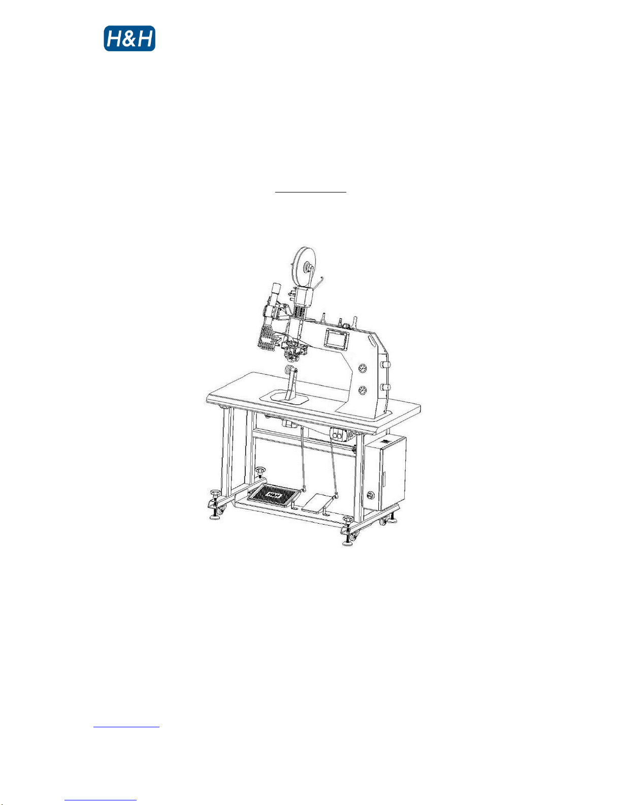
AI-007 Hot Air Sealing Machine
Operation Manual
is powered by
H&H Asia Group Limited
Page 2

AI-007 operation manual
Issue 1 12.10.10, HMI version 13, plc version 29 P. 1 of 43
Table of Content
Precautions Regarding to Safety
Name Plate
Introduction
Specifications
Features
Identification of Components
Front View
Rear View
Cutter Assembly
Heater Positioning Assembly (Front)
Heater Positioning Assembly (Rear)
Main Air Filter Assembly
Compressed air ON/OFF Switch
Pressure Adjustment Panel
Power ON/OFF Switch
Principle of Seam Sealing
Preparation for Installation
Control Method
Touch Screen Control Panel
Foot Switch
Control Menu Navigation
Pressure Adjustment
Start Up And Shut Down Procedures
Start Up Procedures
Shut Down Procedures
Basic Operation
Temperature, Sealing Speed & Pressure Adjustment
Nozzle Position Adjustment
Procedures of Seam Sealing
Tape Cutting
Tape Loading
Page 3

AI-007 operation manual
Issue 1 12.10.10, HMI version 13, plc version 29 P. 2 of 43
Table of Content (cont.)
Advance Operation
Quill Latch
Foot Hold
Differential Speed
Individual Program for Start/ Middle/ End of Tape
Digital Tensioner
Power Save Mode
Parameter Lock
Maintenance
Preventative
Procedures for Replacing Parts
Trouble Shooting
Appendix A Nozzle Air Flow Cross Reference Table
Appendix B Electrical Scheme
Appendix C Wiring Scheme
Appendix D Pneumatic Scheme
Page 4
AI-007 operation manual
Issue 1 12.10.10, HMI version 13, plc version 29 P. 3 of 43
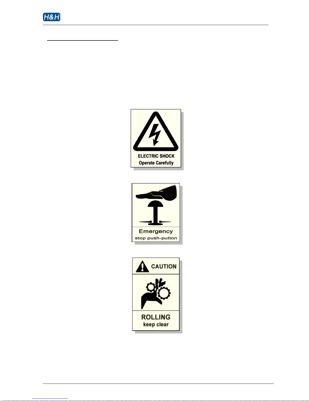
> Precautions Regarding to Safety
Please observe these safety tips for a safe, efficient, and injury free operation of your equipment. By
strictly following all instructions contained in this manual you will certainly obtain an excellent
performance from the use of this equipment for many years.
Page 5
AI-007 operation manual
Issue 1 12.10.10, HMI version 13, plc version 29 P. 4 of 43
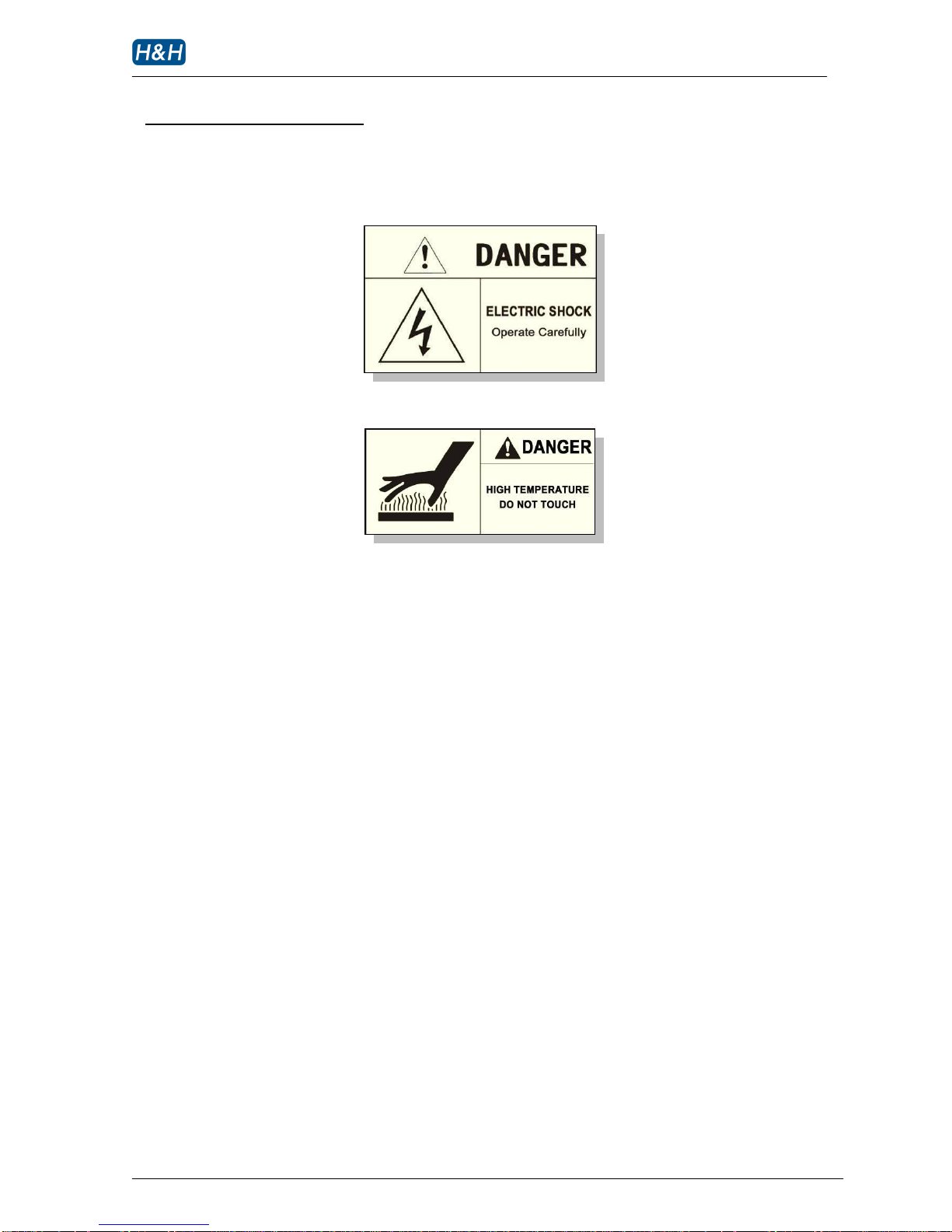
> Precautions Regarding to Safety (cont.)
Page 6
AI-007 operation manual
Issue 1 12.10.10, HMI version 13, plc version 29 P. 5 of 43
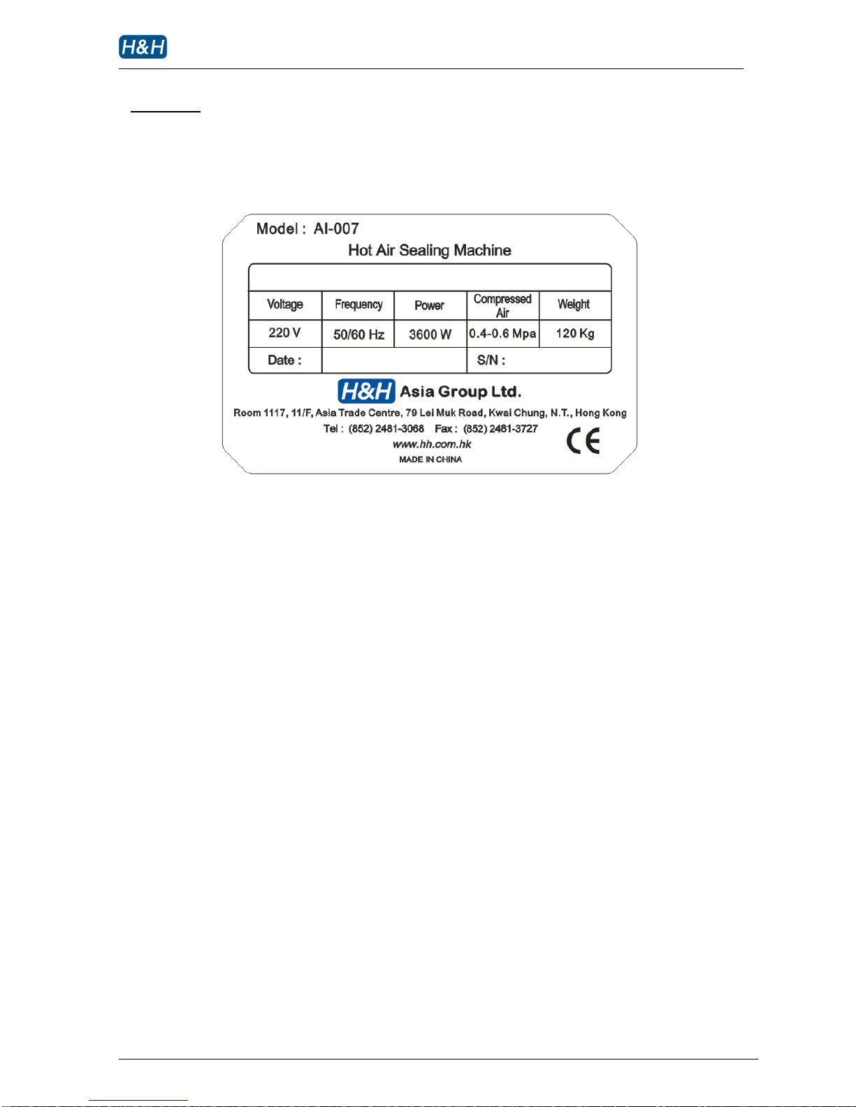
> Name Plate
Page 7

AI-007 operation manual
Issue 1 12.10.10, HMI version 13, plc version 29 P. 6 of 43
> Introduction
Thank you for choosing AI-007 hot air sealing machine by H&H.
The hot air sealing machine described in this manual is one of the most sophisticated machines in the
market today. Built on pure digital platform and designed for the professional users, AI-007
incorporated many new features that makes seam sealing much easier than before. Operators are
recommended to have basic knowledge and skill in seam sealing operation before using this machine.
In order to fully understand how to use this machine properly, and avoid damage to both the machine
and operating personnel, please read this manual carefully and keep it safe for future reference.
Page 8

AI-007 operation manual
Issue 1 12.10.10, HMI version 13, plc version 29 P. 7 of 43
> Specifications
Model : AI-007
Voltage : AC 220 V
Frequency : 50/ 60 Hz
Power Consumption : 3600 W max, 1500 W typical
Compressed Air : 0.4 - 0.6Mpa
Air Consumption : 100 L/min max
Sealing Speed : 1 - 60 ft/min
Nozzle Temperature : 50 – 800C
Nozzle Unit : 22.0 mm standard, other optional
Upper Roller Width : 25.4 mm
Lower Roller Width : 31.0 mm
Overall Dimensions : 1200 mm (L) x 700 mm (W) x 1800 mm (H)
Overall Weight : 120 kg
Note : due to continuous improvement, specifications are subjected to change without prior notification
Page 9

AI-007 operation manual
Issue 1 12.10.10, HMI version 13, plc version 29 P. 8 of 43
> Features
Differential speed for top and bottom rollers, ideal for reducing stretch fabric puckering.
Digital tape releaser for stable operation.
Large size color operator interface.
Power saving mode.
Separate program for tape start/ tape middle/ tape end control.
Multi-function foot pedal for easy one-footed control operation.
Multi-lingual support for touch screen display interface
Page 10
AI-007 operation manual
Issue 1 12.10.10, HMI version 13, plc version 29 P. 9 of 43
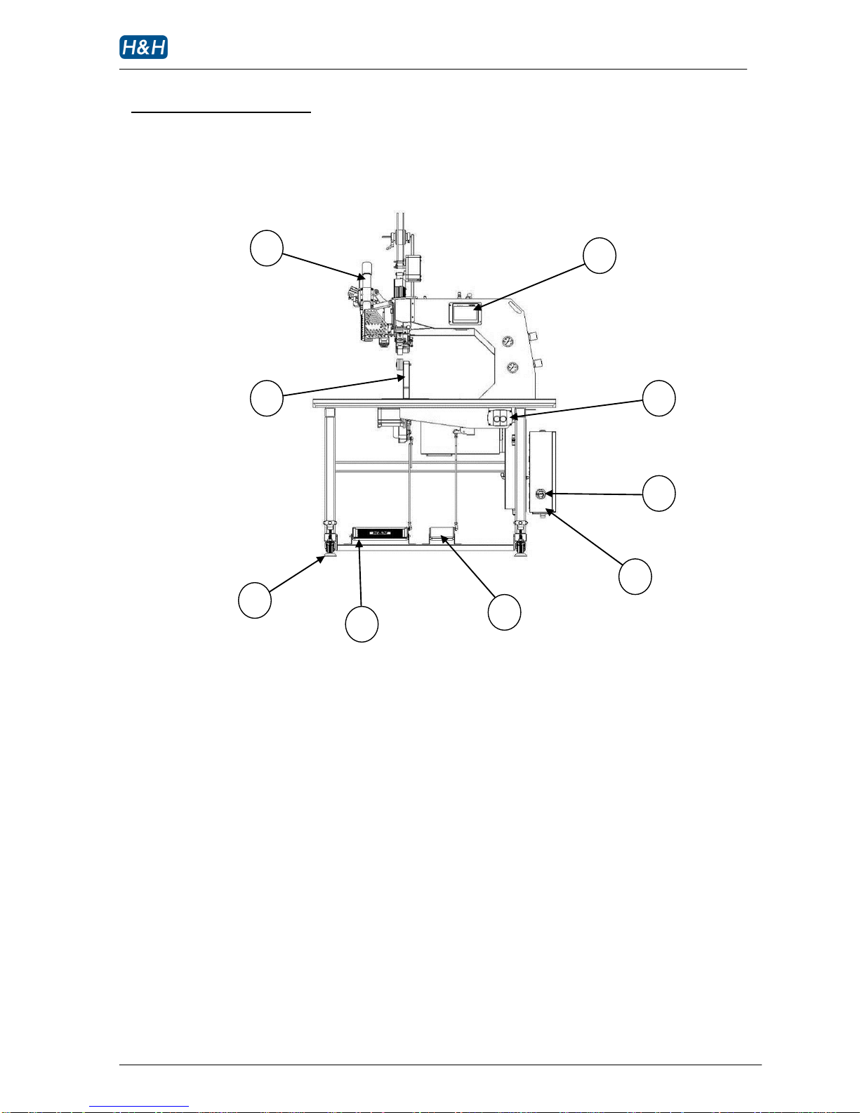
> Identification of Components
>> Front View
1. heater body
2. lower pedestal
3. adjustable floor stand
4. left foot pedal
5. right foot pedal
6. main control box
7. emergency push button
8. power ON/OFF switch
9. touch screen control panel
4 6 1 7 2 8 3 5 9
Page 11
AI-007 operation manual
Issue 1 12.10.10, HMI version 13, plc version 29 P. 10 of 43
> Identification of Components (cont.)
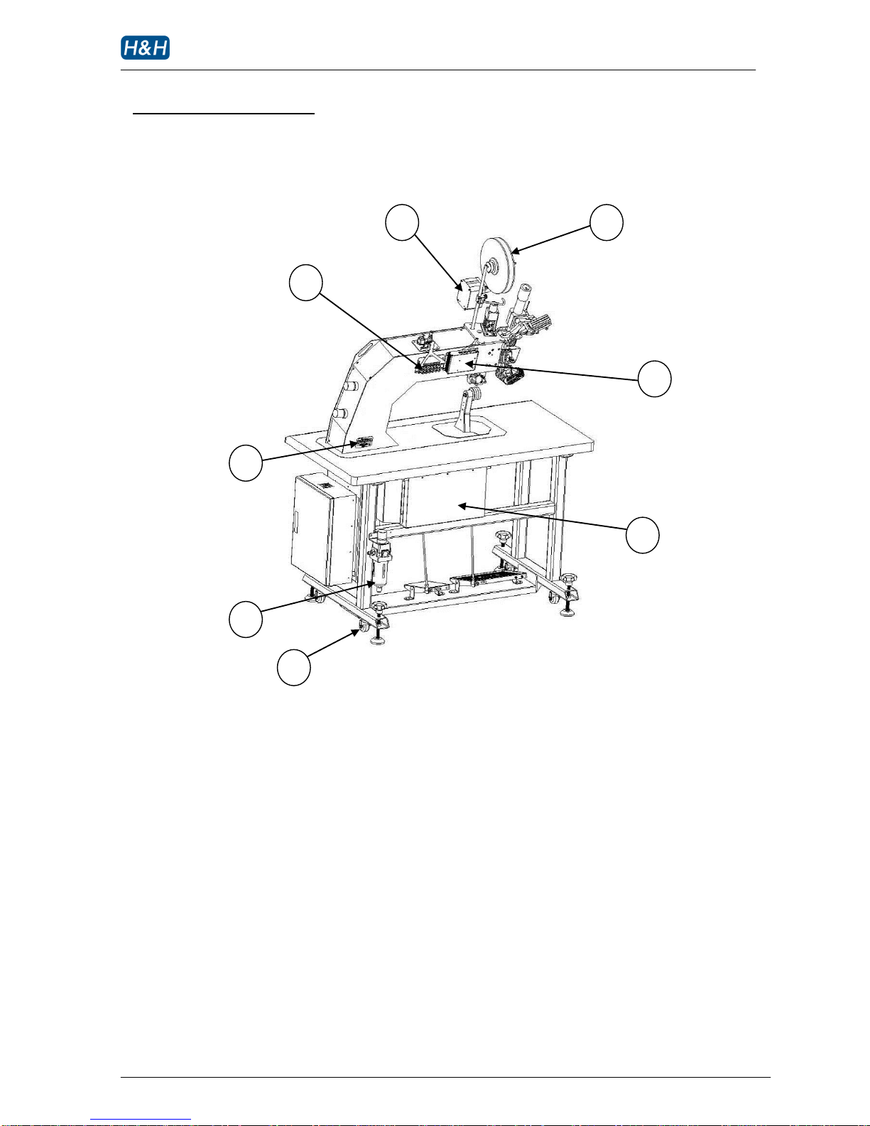
>> Rear View
1. transport caster
2. water filter assembly
3. motor driver box
4. distribution box
5. tape spool
6. tape tensioner
7. pneumatic solenoid cluster
8. name plate
1 4 3 2 8 5 6
7
Page 12
AI-007 operation manual
Issue 1 12.10.10, HMI version 13, plc version 29 P. 11 of 43
> Identification of Components (cont.)
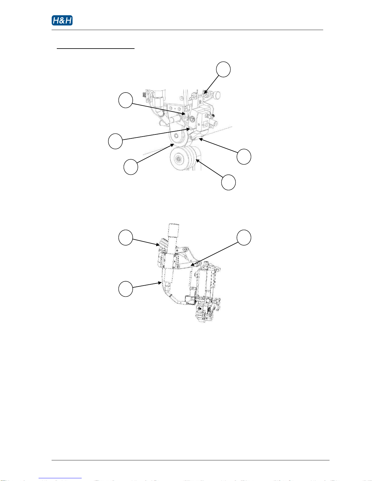
>> Cutter Assembly
>> Heater Positioning Assembly (front)
1. tape clamp
2. movable lower cutter blade
3. presser roller
4. tape stabilizer
5. upper nip roller
6. lower nip roller
7. main swing cylinder
8. temperature sensor
9. heater swing arm
1 2 3 4 8 7 5
6
9
Page 13
AI-007 operation manual
Issue 1 12.10.10, HMI version 13, plc version 29 P. 12 of 43
> Identification of Components (cont.)
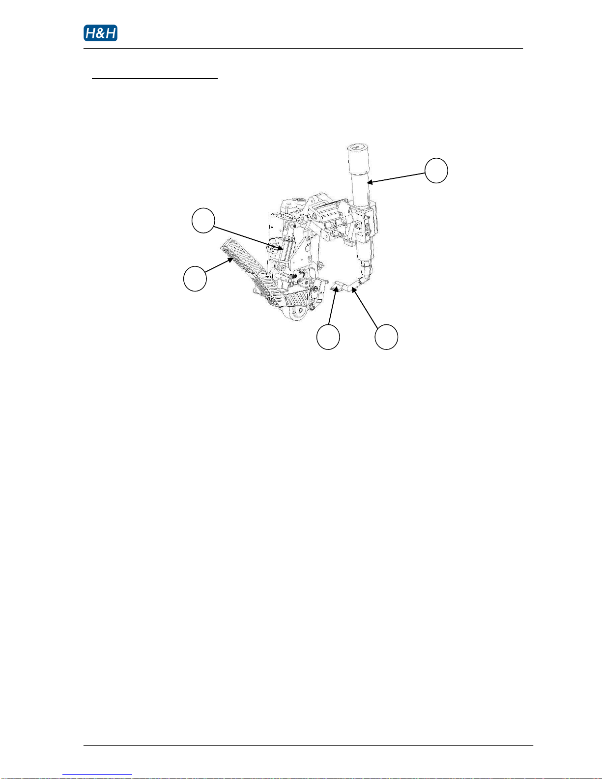
>> Heater Positioning Assembly (rear)
1 auxiliary heater swing cylinder
2 hot air exhaust duct
3 nozzle bit
4 nozzle pipe
5 heater body
1 2 3 4 5
Page 14
AI-007 operation manual
Issue 1 12.10.10, HMI version 13, plc version 29 P. 13 of 43
> Identification of Components (cont.)
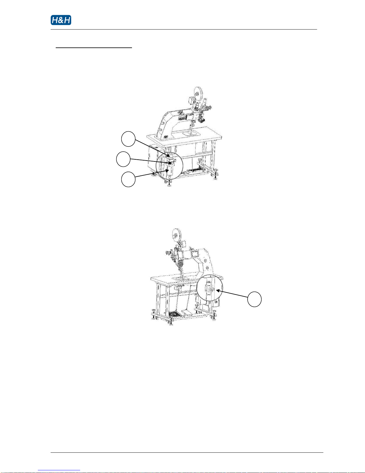
>> Main Air Filter Assembly
>> Compressed air ON/OFF Switch
1 main compressed air pressure regulator
2 main compressed air pressure gauge
3 water filter reservoir
4 compressed air ON/OFF switch
4 1 2
3
Page 15
AI-007 operation manual
Issue 1 12.10.10, HMI version 13, plc version 29 P. 14 of 43
> Identification of Components (cont.)
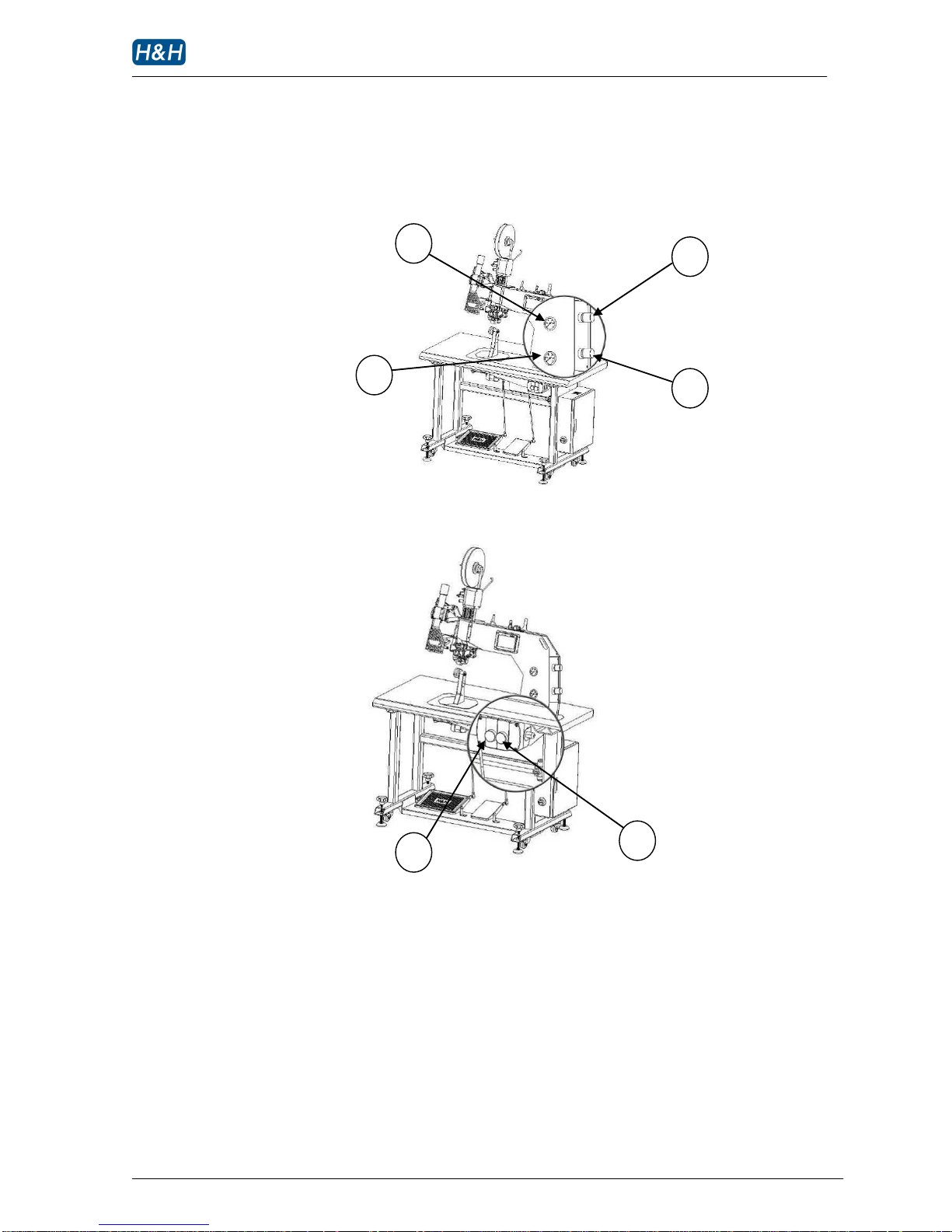
>> Pressure Adjustment Panel
>> Power ON/OFF Switch
1 nozzle air pressure regulator
2 nozzle air pressure gauge
3 nip roller pressure gauge
4 nip roller pressure regulator
5 power ON button (green)
6 power OFF button (red)
5 6 1 4 3
2
Page 16

AI-007 operation manual
Issue 1 12.10.10, HMI version 13, plc version 29 P. 15 of 43
> Principle of Seam Sealing
When seam tape is heated up, the adhesive on the tape is activated. This activated tape is applied on
the water proof coating or lamination of the fabric seam under pressure. When cooled, a strong bond
is formed between the tape and the seam. This bond is so strong that it will prevent pressurized water
from penetrating the sewn seam. As a result, a water proof seam is produced.
A hot air machine, like AI-007, produces hot air with precisely controlled temperature to directly heat
up the adhesive of seam tape. The heated tape and the fabric are feeding into two oppositely rotating
rollers under pressure called nip rollers. The linear speed of the nip rollers is called sealing speed.
During sealing, hot air is being blown out from the nozzle. The hot air that actually reaches the surface
of the tape is a mixture of hot air from the nozzle and surrounding air, hence the actual temperature
that appeared on the tape is somewhat lower than the nozzle temperature. The farther the distance
between the nozzle and the tape, the higher the percentage of surrounding air becomes. On the other
hand, a higher hot air flow rate will reduce the percentage of surrounding air causing the hot air
temperature appeared on the tape to be higher. So both the nozzle position and hot air flow rate are
very important factors.
So, the major factors that can affect the seam sealing are as follows:
Hot air temperature
Sealing speed
Nozzle air pressure
Air flow rate
Nozzle position
When a consistent product is required, the combination of the above factors have to be set precisely
since their effects towards a proper sealing are all interconnecting.
Page 17
AI-007 operation manual
Issue 1 12.10.10, HMI version 13, plc version 29 P. 16 of 43
> Preparation for Installation
Installation must be carried out by authorized personnel. Follow the steps below:
1. Position the machine on a flat surface and allow at least 50cm clearance on both sides as well as
the back side, this is essential for the hot air deflector to work properly and also to allow enough
room for carrying out necessary service and maintenance
2. Adjust the foot stand so that the machine is level and stable.
3. Cut loose all packing cable ties and materials in order to free up all machine movements.
4. Connect the power plug to a suitable outlet with at lease 15A capacity.
5. Locate the air hose supplied with the machine. Connect one end to the inlet of the water filter at
the back side of the machine; connect the other end to a compressed air supply such as air
compressor or central air supply. Make sure the compressed air supply has at least 0.6 Mpa (6 bar)
of pressure and a flow rate of no less than 100L/min.
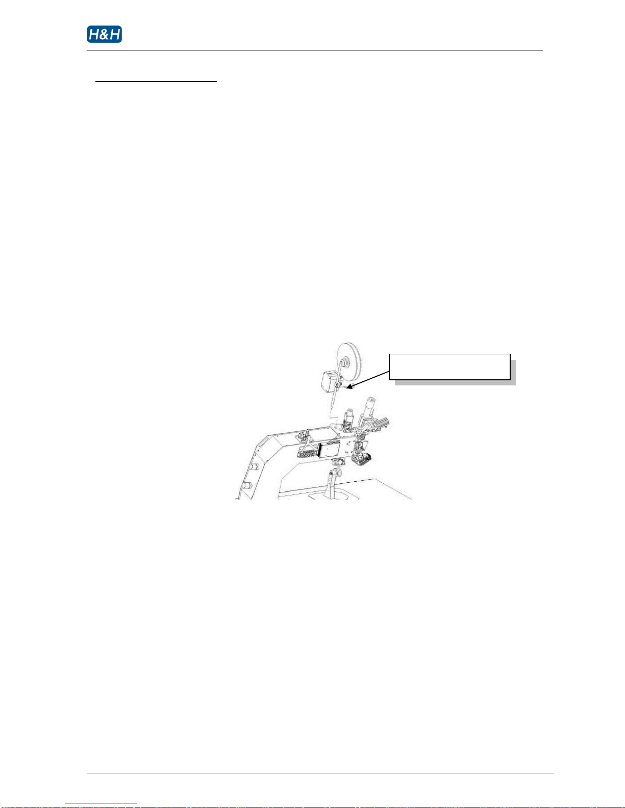
6. Install the tape dispenser assembly at the top of the machine and align the tape spool at right
angle to the width of the machine. (see diagram below)
7. Install a roll of seam tape with the adhesive side facing the operator (refer to the section on tape
loading).
8. The machine is now ready for operation.
Install tape dispenser assembly
Page 18
AI-007 operation manual
Issue 1 12.10.10, HMI version 13, plc version 29 P. 17 of 43
> Control Method
>> Touch Screen Control Panel
Almost all settings and timing control of the machines can be input from the touch screen control
panel. Use you finger tip to touch the parameter to be modified. Switch to different pages to
modify other parameters (refer to section on control menu navigation). The screen has a protective
cover to prevent the surface from damage and scratch, however, avoid using excessive force when
touching the panel.
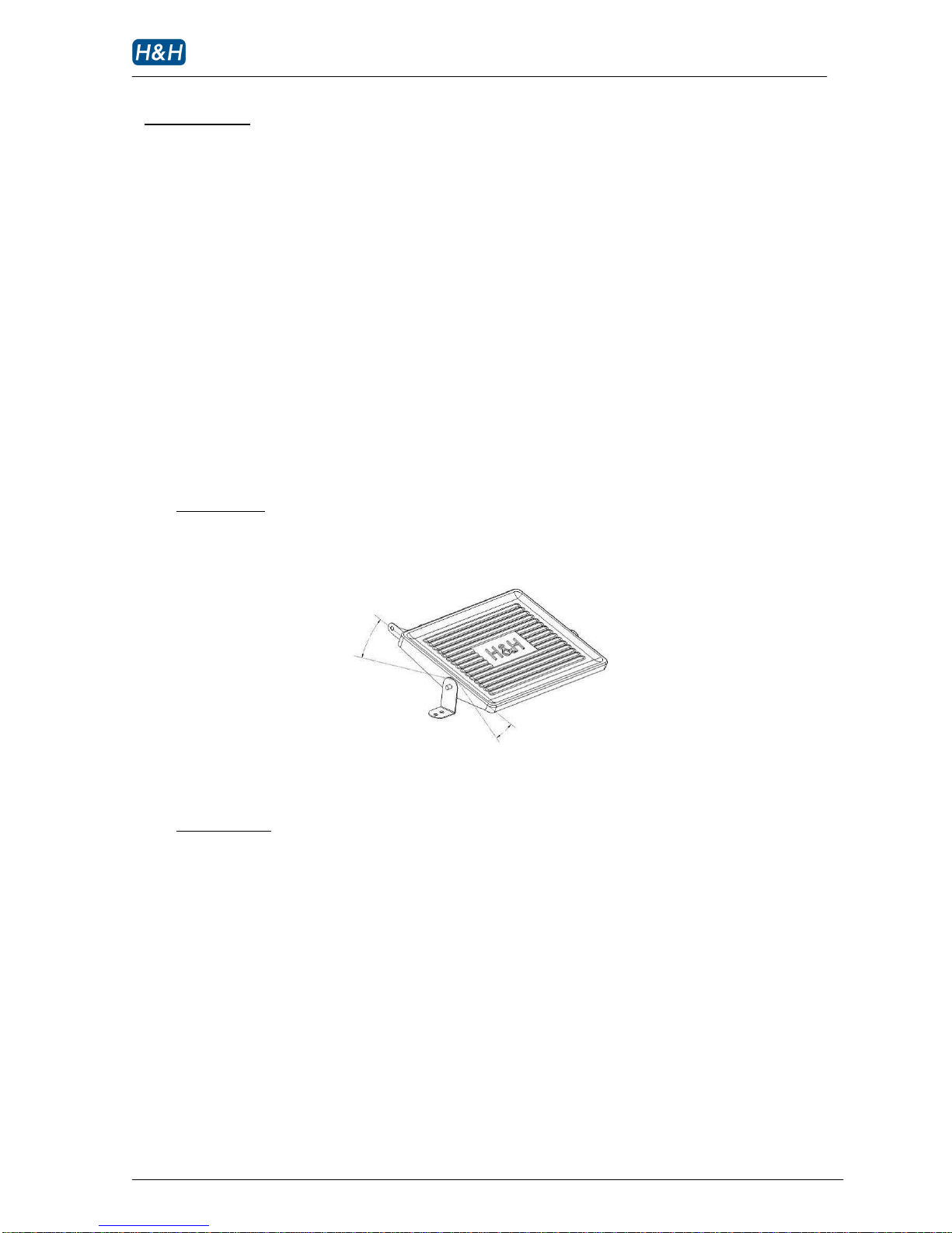
>> Foot Switch
There are 2 foot pedals for the machine. The design of these pedals is such that they can be
operated either individually or in combination to achieve a number of preset tasks by the operator’s
feet alone. As a result, the operator’s hands are free to manipulate the processing fabric.
Left foot pedal
The left pedal is a multi function pedal. You can use it to raise the upper roller and start sealing
To raise the upper roller - heel back the left foot pedal.
To start sealing - press forward.
Right foot pedal
The right pedal is a simple ON/OFF switch. It performs different function according to the timing
of activation
During idle – jog function that makes the rollers rotate forward without the nozzle coming in.
During sealing – cut function that cuts the tape
While left foot pedal is heel back – perform tape cutting function
Page 19
AI-007 operation manual
Issue 1 12.10.10, HMI version 13, plc version 29 P. 18 of 43
> Control Method (cont.)
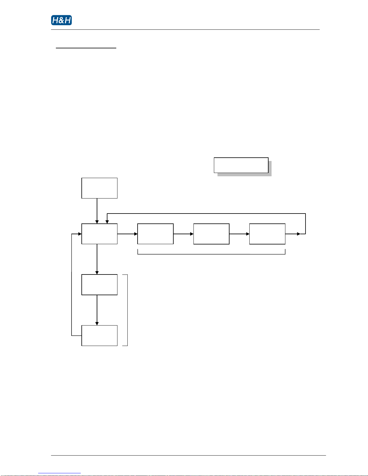
>> Control Menu Navigation
The AI-007 has many parameters that can be adjusted according to the operational situations.
These parameters are arranged in different menu pages on the touch screen control panel according
to their functionality. The structure of the menu page arrangement is represented in the following
diagram.
operation menu group
supplier
information
main
tape start
tape middle
tape end
personality
AI-007 Menu Structure
support menu group
language
Page 20
AI-007 operation manual
Issue 1 12.10.10, HMI version 13, plc version 29 P. 19 of 43
> Control Method (cont.)
>> Control Menu Navigation (cont.)
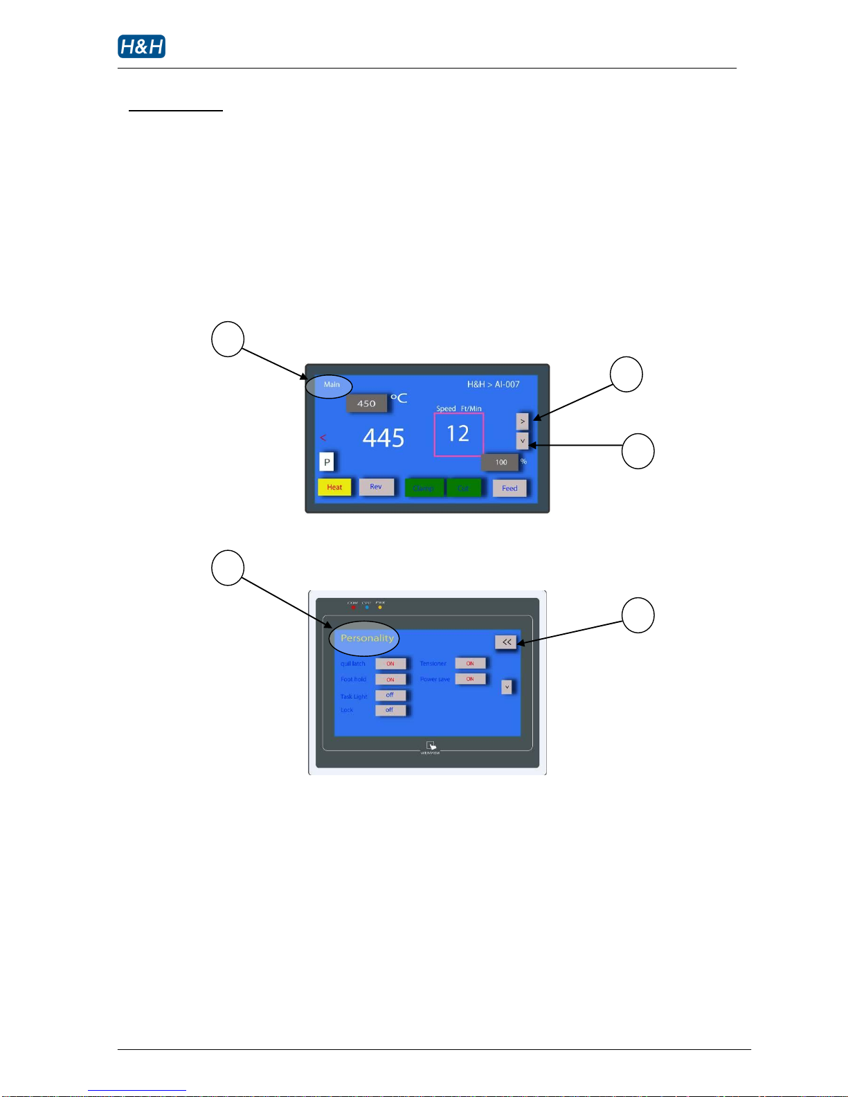
The followings are typical menu pages, all of them have names at the top left corner for easy
identification. Right arrow buttons are for navigating in the operation menu group. Down arrow
buttons are for navigating in the support menu group. Please note that page ‘main’ is the hub of the
menu network so only this page has navigation buttons for both operation and support menu groups.
1 page name
2 next page in the operation menu group
3 hot key to return to page ‘main’
4 next page in the support menu group
1 2 4
3
1
Page 21
AI-007 operation manual
Issue 1 12.10.10, HMI version 13, plc version 29 P. 20 of 43
> Control Method (cont.)
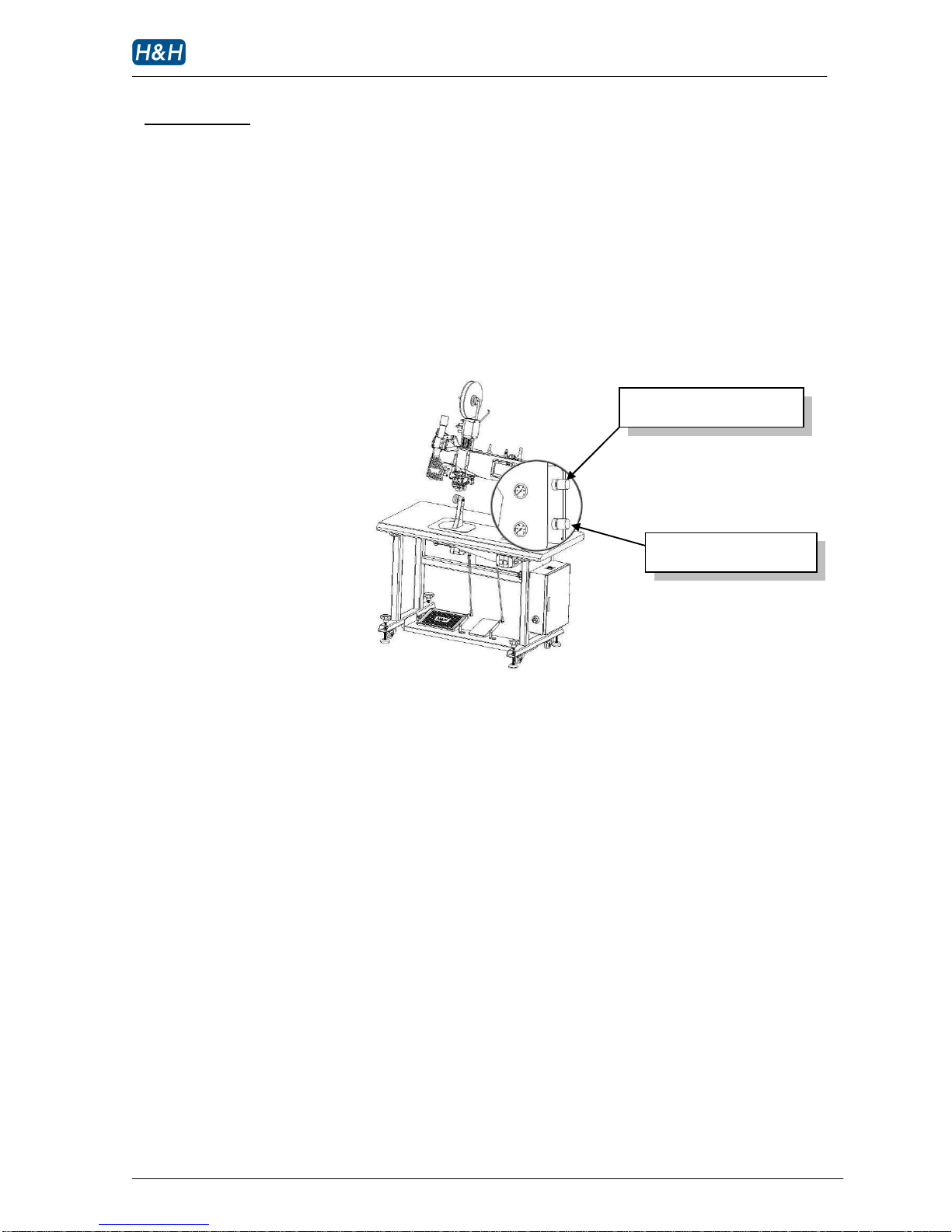
>> Pressure Adjustment
To adjust corresponding pressure, pull out the adjusting knob by one notch, turn the knob clockwise
or anti-clockwise to increase or decrease the needed pressure accordingly. When finished, lock the
air regulator pressure by pushing the adjusting knob toward the regulator.
Nozzle air pressure regulator
Nip roller pressure regulator
Page 22
AI-007 operation manual
Issue 1 12.10.10, HMI version 13, plc version 29 P. 21 of 43
> Start Up and Shut Down Procedures
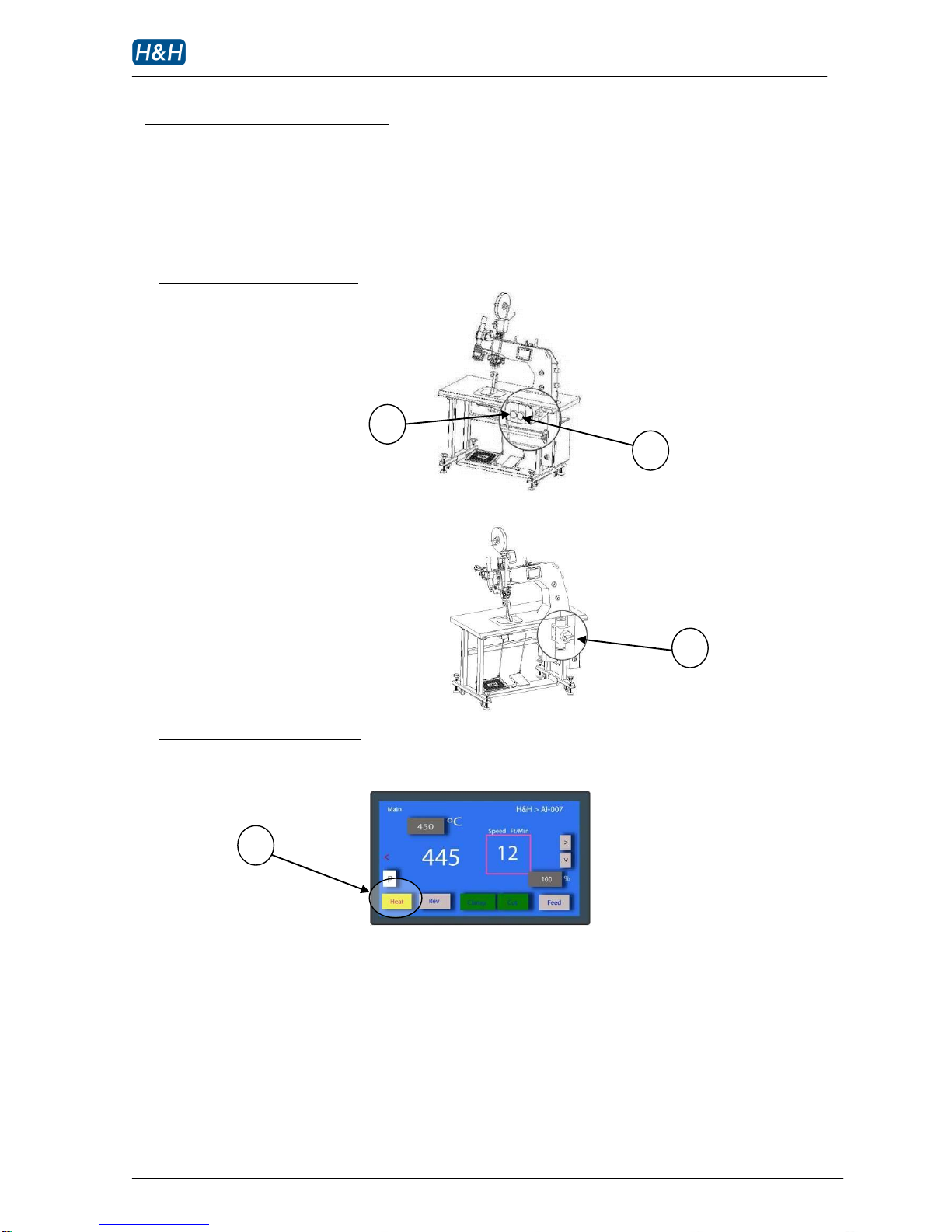
Both start up and shut down procedures are extremely important to the well being of AI-007, please
take steps to follow the procedures described.
Location of power ON/OFF switch
Location of main air supply ON/OFF switch
Location of heater ON/OFF button
1 power OFF button
2 power ON button
3 main air ON/OFF switch
4 heater ON/OFF button
1 2 3
4
Page 23
AI-007 operation manual
Issue 1 12.10.10, HMI version 13, plc version 29 P. 22 of 43
> Start Up and Shut Down Procedures (cont.)
>> Start up Procedures
1 Turn on the machine by pressing the green power ON button
2 Switch on the compressed air by turning the main air ON/OFF switch knob
3 Enable the heating by pressing the HEAT button.
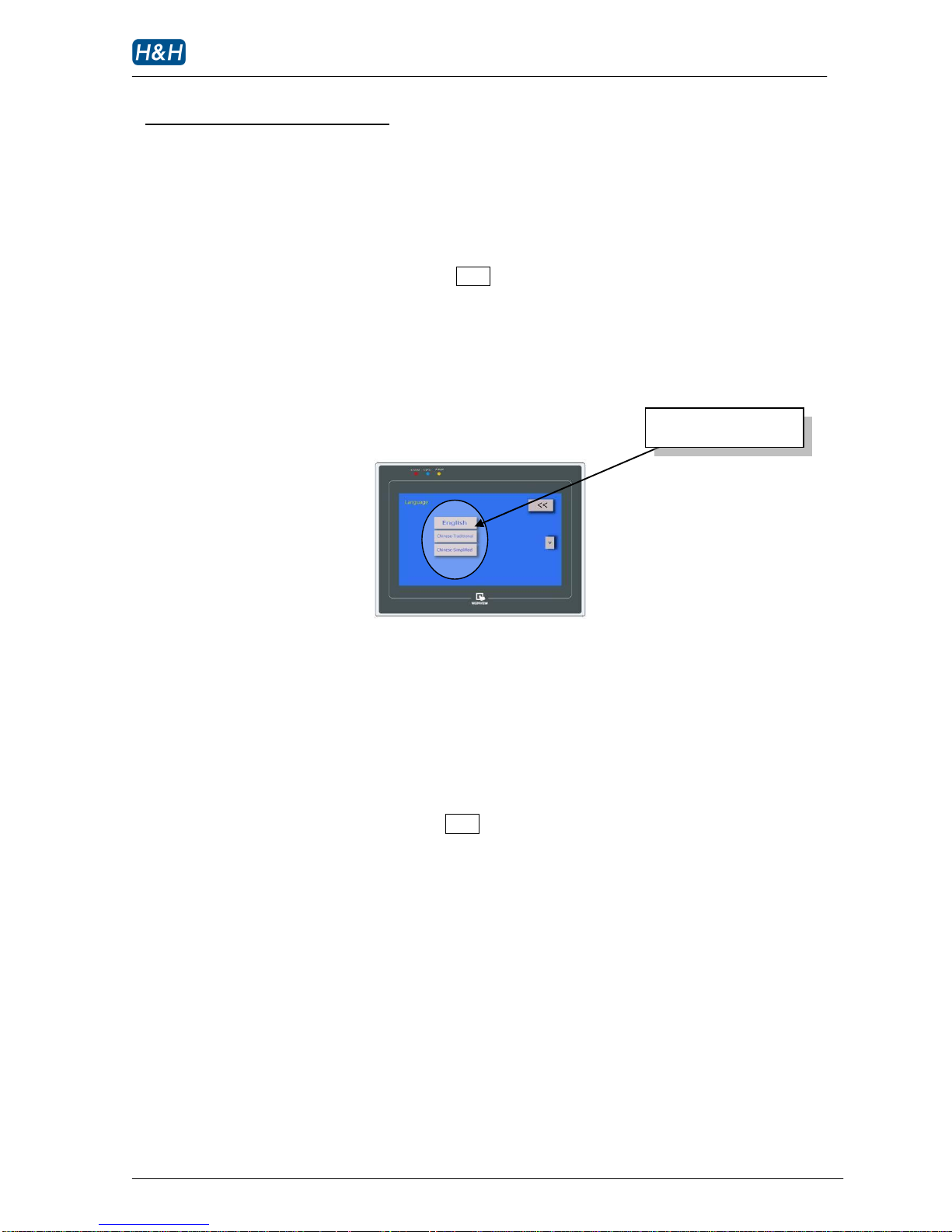
The machine display will indicate various information including company contact information and
software versions of the machine. After about 20 seconds, the page ‘main’ is displayed meaning the
machine is ready for operation. While the software version page is displayed, you can choose the
preferred language.
The display will store this selection even the power is off.
>> Shut down Procedures
WARNING !
Please follow the shut down procedures strictly to avoid damage to the heater. Always cool
down the heater before shutting off the compressed air supply.
1 Disable the heating by pressing the HEAT button if the machine is previously in the heating
mode.
2 Observe the indicated nozzle temperature, the temperature should start to drop.
3 Wait until the nozzle temperature is below 60 C, depending on the previous temperature and
surrounding environment, it may take 5-10 minutes.
4 Confirm that the temperature is below 60 C, then switch off the machine by pressing the red
power OFF button.
5 Follow by switching off the compressed air by turning the main air ON/OFF switch knob.
Select preferred language
Page 24
AI-007 operation manual
Issue 1 12.10.10, HMI version 13, plc version 29 P. 23 of 43
> Basic Operation
>> Temperature, Sealing Speed & Pressure Adjustment
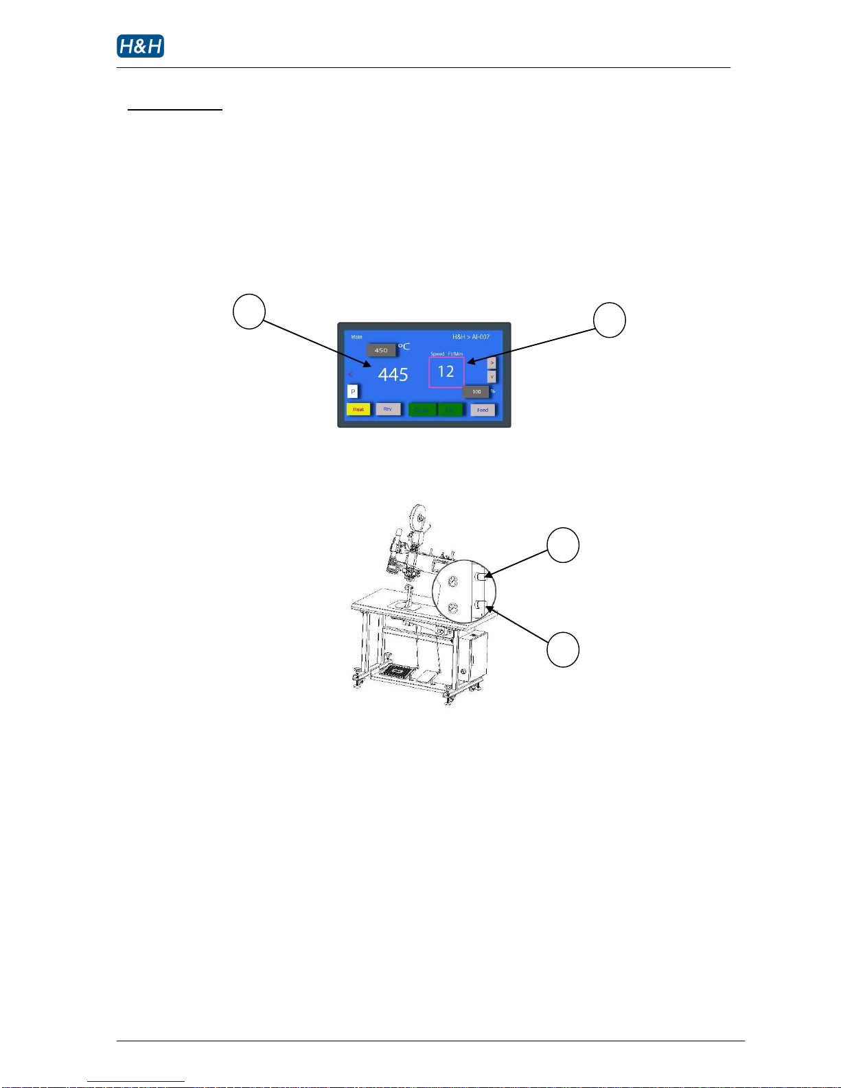
Please note the locations of basic parameters that you need to set before operating the machine.
Refer to the corresponding sections for detail explanation.
1 temperature
2 sealing speed
3 nip rollers pressure
4 nozzle air pressure
1 2 3
4
Page 25
AI-007 operation manual
Issue 1 12.10.10, HMI version 13, plc version 29 P. 24 of 43
> Basic Operation (cont.)
>> Nozzle Position Adjustment
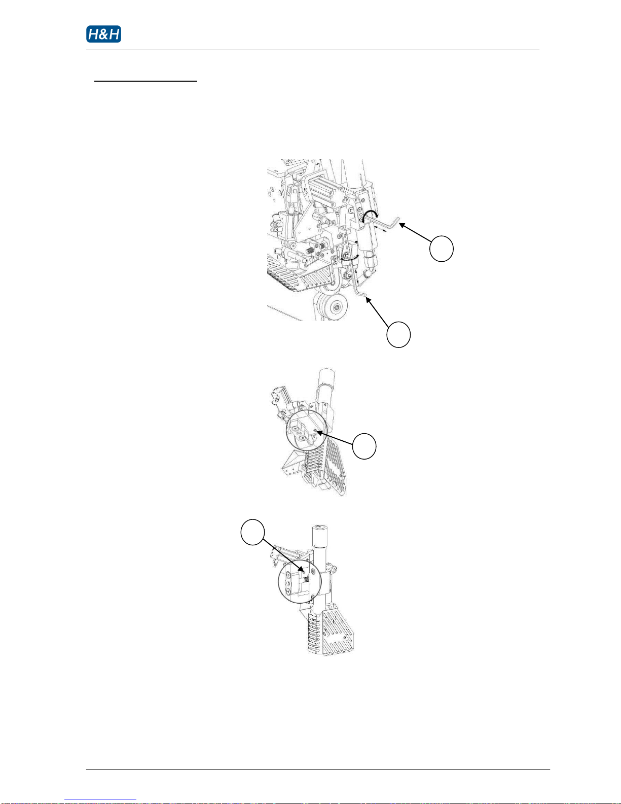
2 1 3
4
Page 26
AI-007 operation manual
Issue 1 12.10.10, HMI version 13, plc version 29 P. 25 of 43
> Basic Operation (cont.)
>> Nozzle Position Adjustment (cont.)
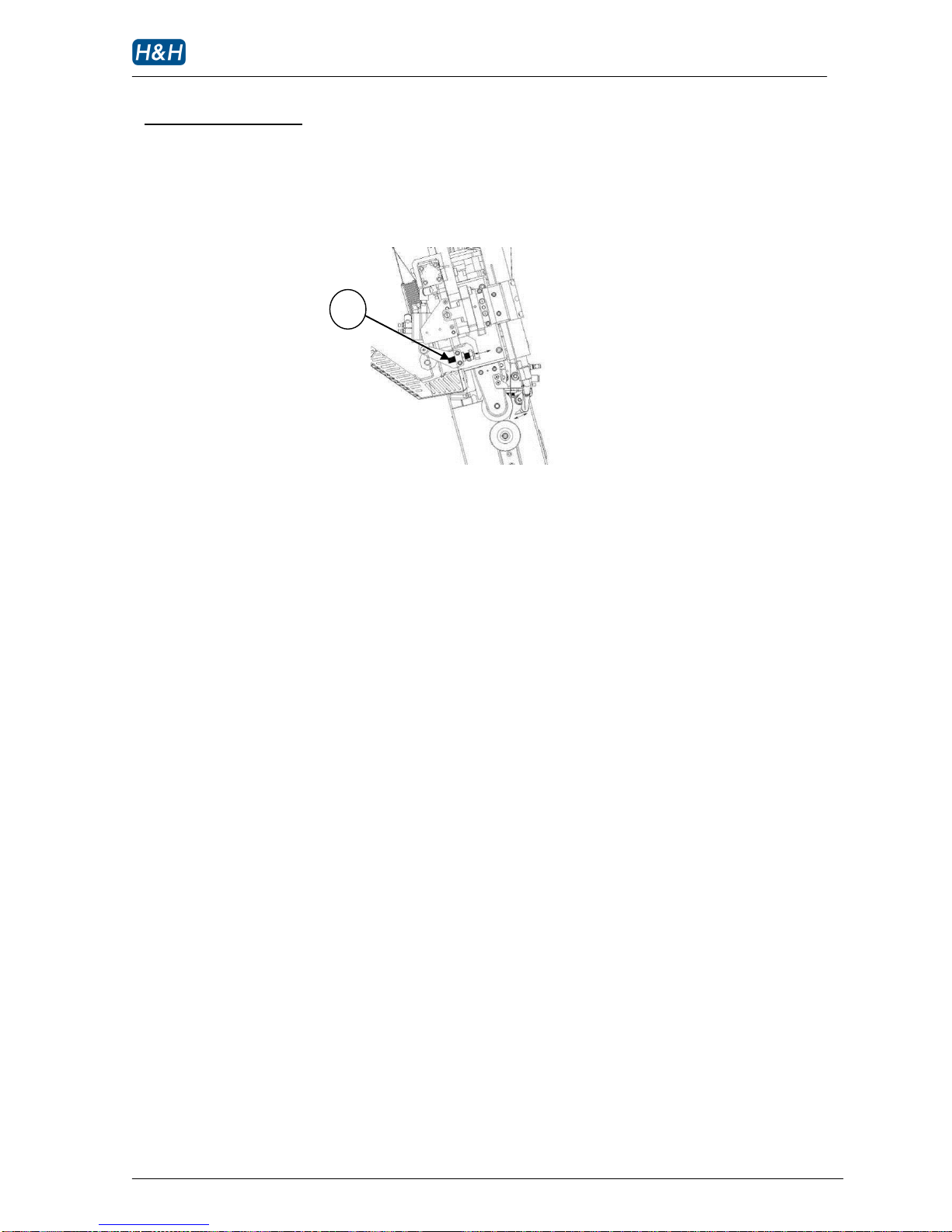
1 nozzle position (left-right adjustment)
2 nozzle position (up-down adjustment)
3 nozzle left-right adjustment locking screw
4 nozzle up-down adjustment locking screw
5 nozzle position (far-near adjustment)
5
Page 27

AI-007 operation manual
Issue 1 12.10.10, HMI version 13, plc version 29 P. 26 of 43
> Basic Operation (cont.)
>> Procedures of Seam Sealing
Set the heater temperature, nozzle air pressure and fabric speed to the desired values. To begin
with, set to 400°C, 0.1Mpa and 12ft/min accordingly. This should be a fair setting to start with.
However, other setting can be used depending on the actual situation.
Activate the RUN (left foot) pedal momentarily, check the position of the nozzle and adjust
accordingly.
Insert the seam tape through the tape stabilizer and the white tape presser roller, activate the JOG
(right foot) pedal to advance the tape towards the nip rollers. The tape must be position in the
middle and with the adhesive side facing towards the operator. Adjust the sealing tape to proper
tension and running position (refer to section on tape loading)
Raise the upper nip roller by heeling back the left foot pedal, put the tape and the sewn seam in the
center and release the left foot pedal so that the upper nip roller presses on the tape and seam
tightly.
Collect the seam with both hands until the starting point can be reached by fingers. Position the
forearms on the table and smooth out the seam with your fingers.
Activate the RUN (left foot) pedal, the hot air nozzle will engage and the nip rollers will start
turning and draw the tape and the seam in between the nip rollers. Release the seam while keeping
it in the center of the lower nip roller.
Near the end of tape, step on the right foot pedal while left foot pedal is still down. This will cut the
tape, the upper nip roller will rise and new section of tape is fed.
The first seam sealing is completed; resume sealing for the next seam.
>> Tape Cutting
During sealing - while the left foot pedal is in forward sealing position, press on the right foot to cut
the tape.
Idling – manually press the CUT button on the touch screen to cut the tape
Idling – while the left foot pedal is in the heel back position, press on the right foot to cut the tape.
Page 28
AI-007 operation manual
Issue 1 12.10.10, HMI version 13, plc version 29 P. 27 of 43
> Basic Operation (cont.)
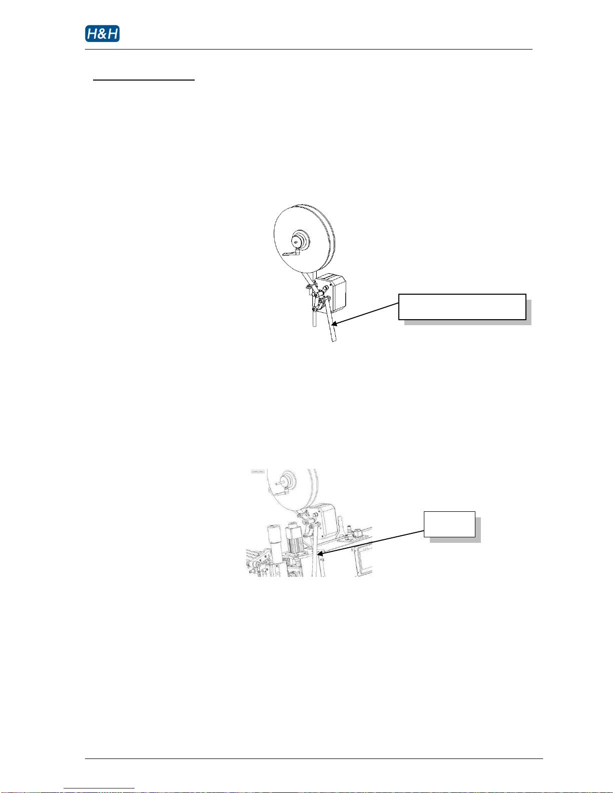
>> Tape Loading
Load the tape on the spool and route the tape thru the tape dispenser as shown below. Make sure
the adhesive side of the tape is facing the operator when installing the tape.
Next guide the tape thru various path and guide as shown below:
Seam tape
Adhesive facing toward operator
Page 29
AI-007 operation manual
Issue 1 12.10.10, HMI version 13, plc version 29 P. 28 of 43
> Basic Operation (cont.)
>> Tape Loading (cont.)
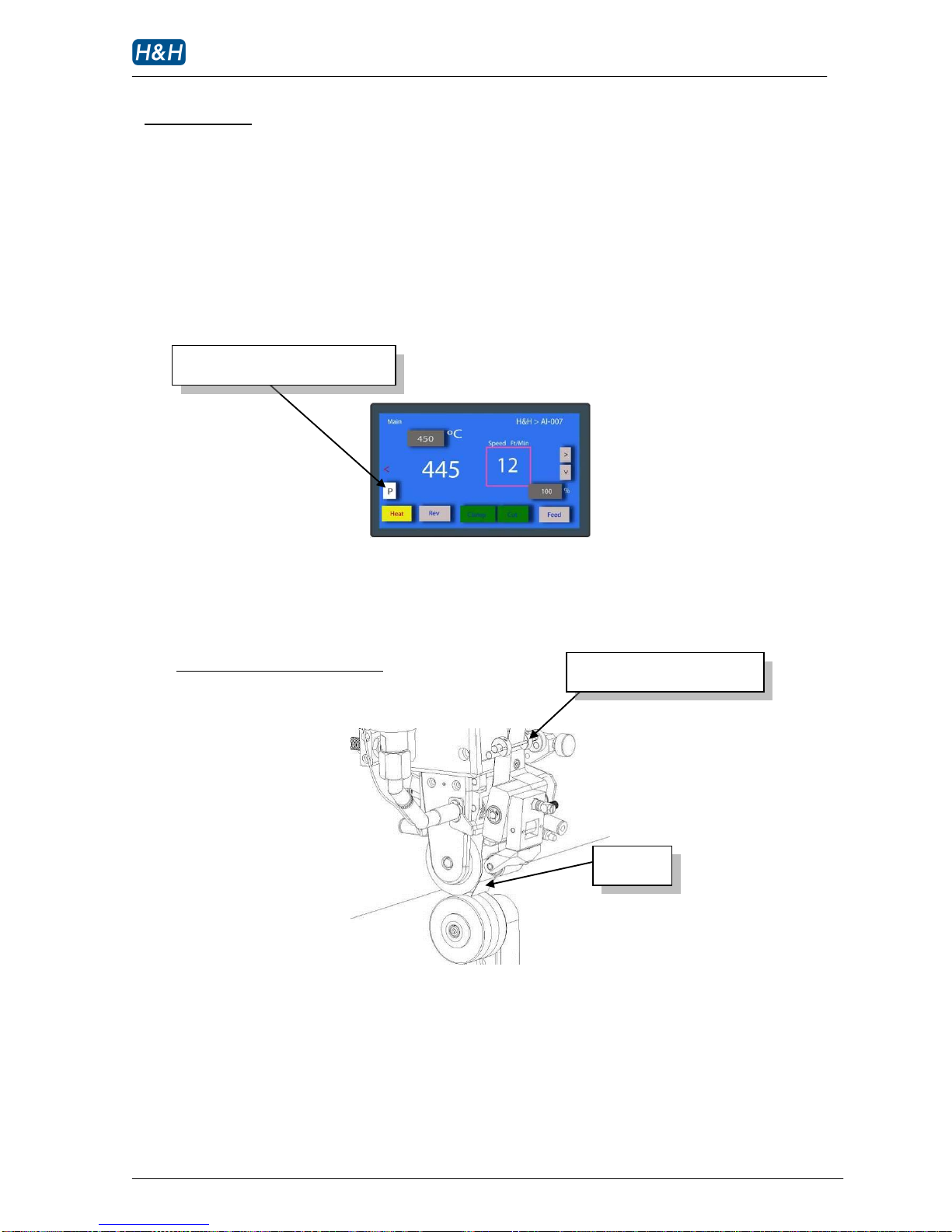
When inserting the tape thru the cutter area, it is best to place the nozzle in the park position. At
this time, the tape clamp will be released to facilitate the tape insertion.
Go to page ‘main’ and press the nozzle parking button.
When parked, the nozzle is moved to a position farther away from the operator. This gives a cleaner
look at the cutter opening for a more convenient tape loading. This is also safer as the chance of
getting burn by the nozzle is minimized.
Tape installation in the cutter area
After loading, press the park button again to bring the nozzle back to standby position. Press the
right foot pedal to jog the rollers and make sure the tape is running at the center of the rollers
smoothly. Adjust the side guides to shift tape if needed.
Press to park or un-park the nozzle
Adjust side guides to center tape
Seam tape
Page 30

AI-007 operation manual
Issue 1 12.10.10, HMI version 13, plc version 29 P. 29 of 43
> Advance Operation
In the past, hot air machines had been built with similar technology. Factory users were forced to
compromise between quality and efficiency as fundamental problems in seam sealing still exist in day
to day production.
The AI-007 hot air sealing machine is engineered to make seam sealing much easier than before.
Unique features allow you to fine tune sealing conditions in the time domain level, eliminating
traditional problems.
These features including but not limiting to the follows:
Quill latch
Foot hold
Differential speed
Duplex nozzle action
Individual program for start/ middle/ end of tape
Digital tensioner
Power save mode
Parameters lock
Page 31
AI-007 operation manual
Issue 1 12.10.10, HMI version 13, plc version 29 P. 30 of 43
> Advance Operation (cont.)
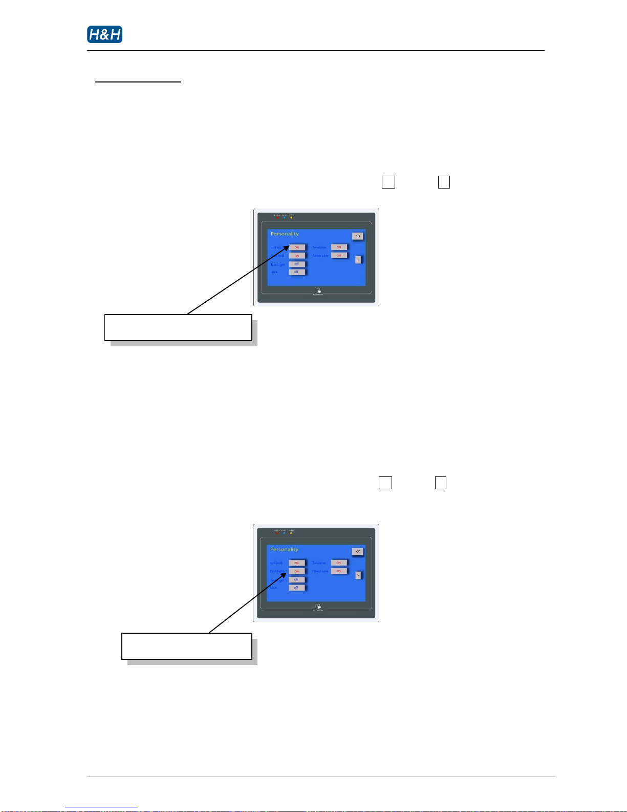
>> Quill Latch
This feature allows the upper roller to latch in the up position after tape is cut.
To enable this function, press the corresponding button until off becomes on..
If this function is not enabled, the upper roller will come down after the tape is fed.
>> Foot Hold
This feature is used to control the after cut sequence.
To enable this function, press the corresponding button until off becomes on. During this mode, the
after cut sequence will be finished even the left foot pedal is released after the cutting.
If this function is not enable, the after cut sequence is cancelled when left foot pedal is released.
Press to ON to enable quill latch
Press to ON to enable foot hold
Page 32
AI-007 operation manual
Issue 1 12.10.10, HMI version 13, plc version 29 P. 31 of 43
> Advance Operation (cont.)
>> Differential Speed
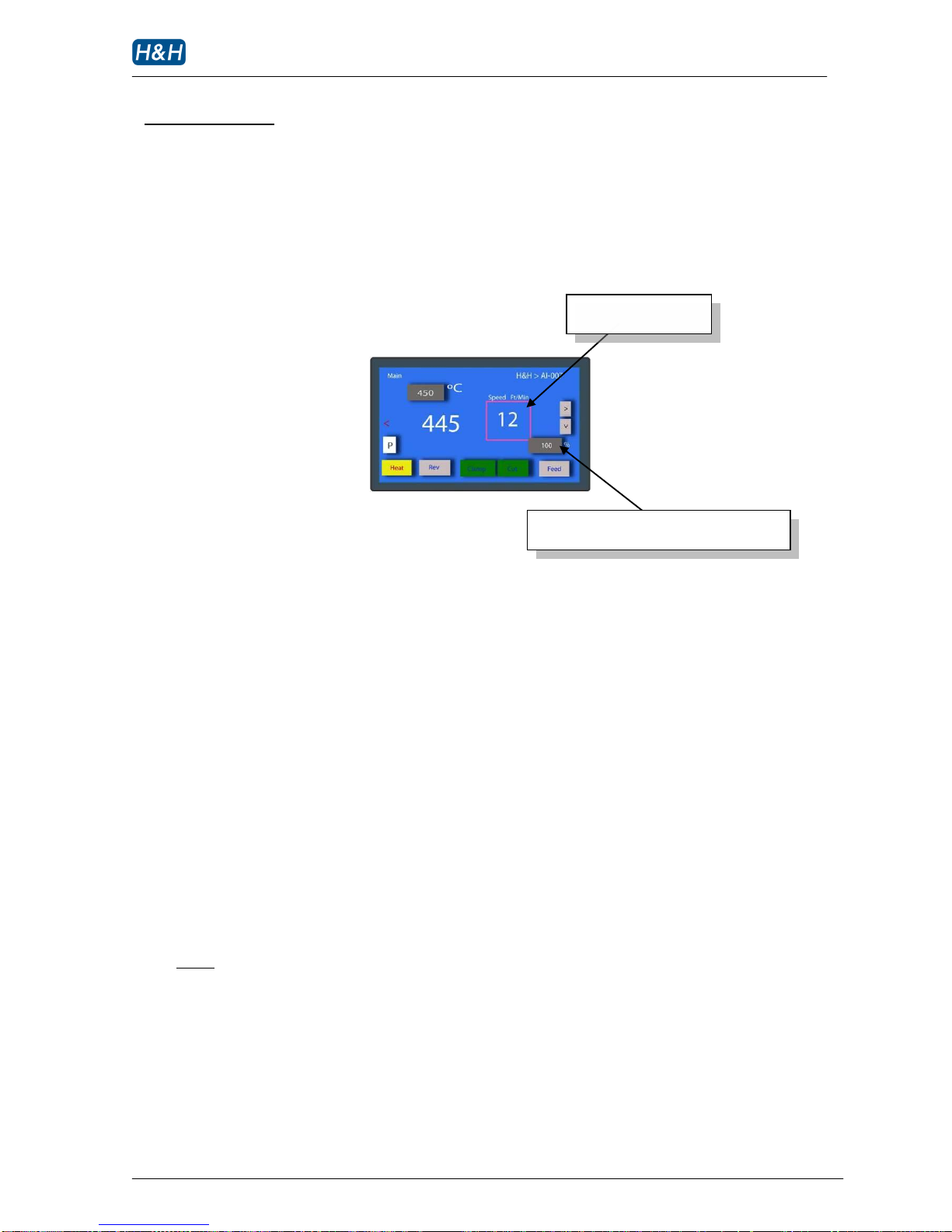
This feature allows the operator to set the upper and lower rollers to run at a slightly different
speed.
While the upper roller is running at the preset sealing speed, the lower roller is running at a speed
according to the % (percentage) setting.
Lower roller speed = preset sealing speed x % setting
If differential speed setting = 100%, roller is running at the same speed as the upper roller.
If differential speed setting > 100%, roller is running at a faster speed than the upper roller.
If differential speed setting < 100%, roller is running at a slower speed than the upper roller.
The range of percentage setting is 80–150 %.
WARNING !
When using larger differential speed < 90% or > 110%. Always place a piece of fabric
between the nip rollers. Failure to do so may cause excessive stress in the transmission
system which may in turn damage the machine parts
Usage:
To compensate puckering due to stretchiness of fabric
To compensate puckering due to uneven worn out of upper and bottom rollers
To improve a phenomenon called ‘bamboo shell’ on some kind of fabric
Press to change the differential speed in %
Preset sealing speed
Page 33
AI-007 operation manual
Issue 1 12.10.10, HMI version 13, plc version 29 P. 32 of 43
> Advance Operation (cont.)
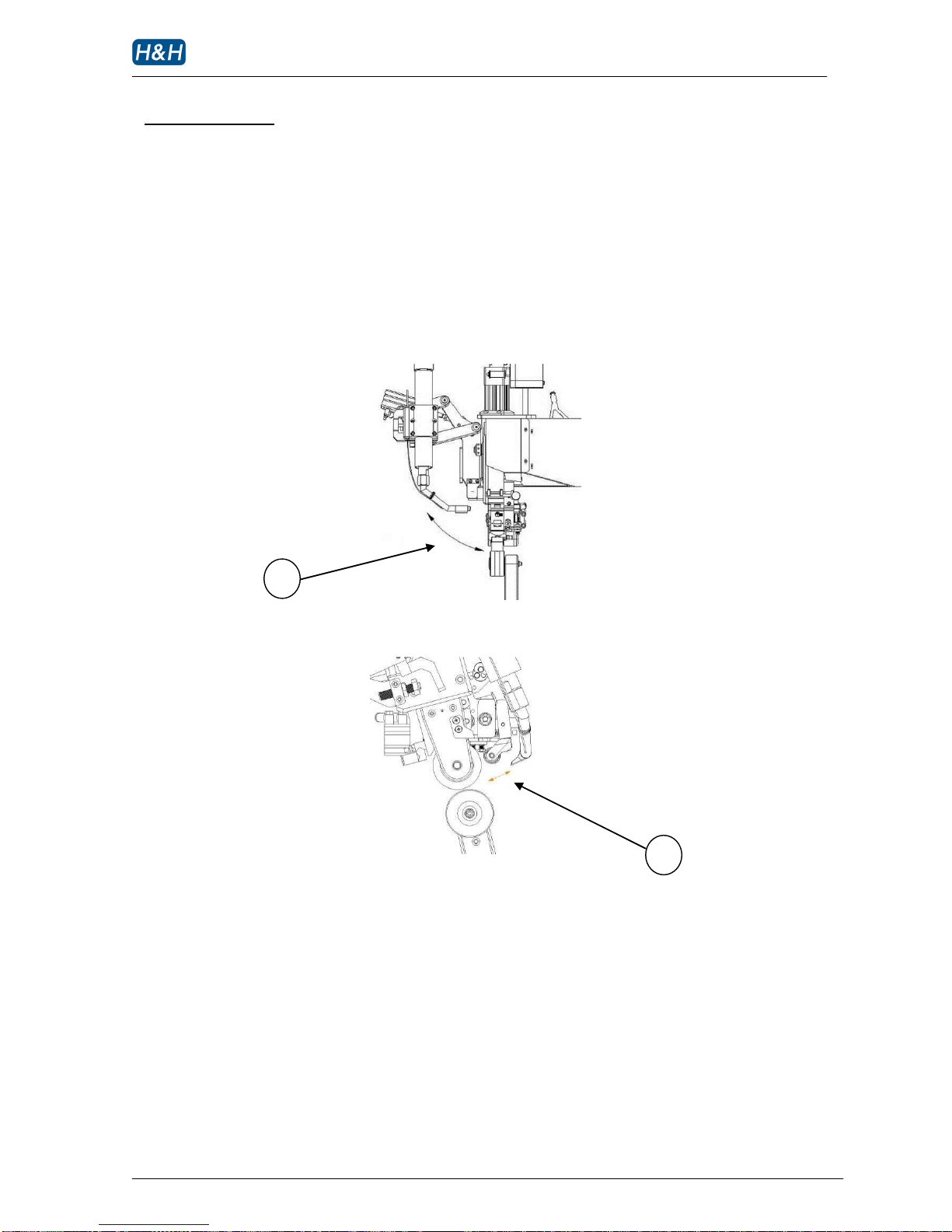
>> Duplex Nozzle Action
The nozzle action, or path is controlled by two cylinders. One is for left-right direction and the
other one is for far-near direction. Hence the action is duplex.
This feature significantly improves the seam sealing quality especially on thin and soft tape.
1 nozzle swing in the LEFT to RIGHT direction
2 nozzle swing in the IN and OUT direction
1
2
Page 34
AI-007 operation manual
Issue 1 12.10.10, HMI version 13, plc version 29 P. 33 of 43
> Advance Operation (cont.)
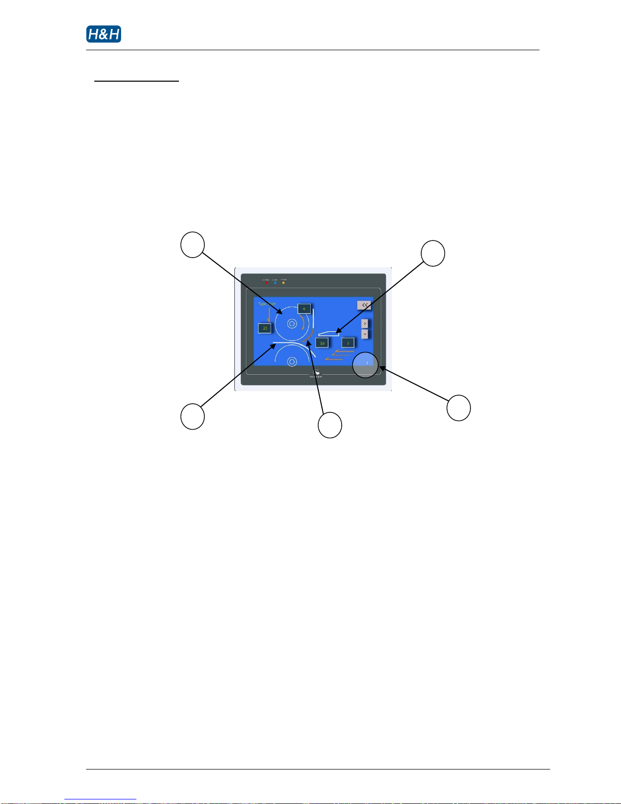
>> Individual Program for Start/ Middle/ end of Tape
AI-007 can recognize the stage of sealing the machine is processing, individual programs can be used
to change the behavior of the machines according to whether the stage is in the start, middle or end
of sealing. To invoke the set up pages of these programs, touch the respective area in the seam tape
graphic symbols as illustrated below:
1 upper roller symbol
2 fabric symbol
3 seam tape symbol
4 tape section programming indicator
5 air nozzle symbol
On the individual programming pages, parameters that can be altered are represented by
blinking symbols. Touch these symbols to enter into corresponding data entry mode. Simple
explanation and range of the parameter will be shown up at this time.
Note: since the operating software is being upgraded constantly to accommodate new features, please refer to the on screen
menu on the touch screen control panel for further explanation.
1 5 4 3 2
Page 35
AI-007 operation manual
Issue 1 12.10.10, HMI version 13, plc version 29 P. 34 of 43
> Advance Operation (cont.)
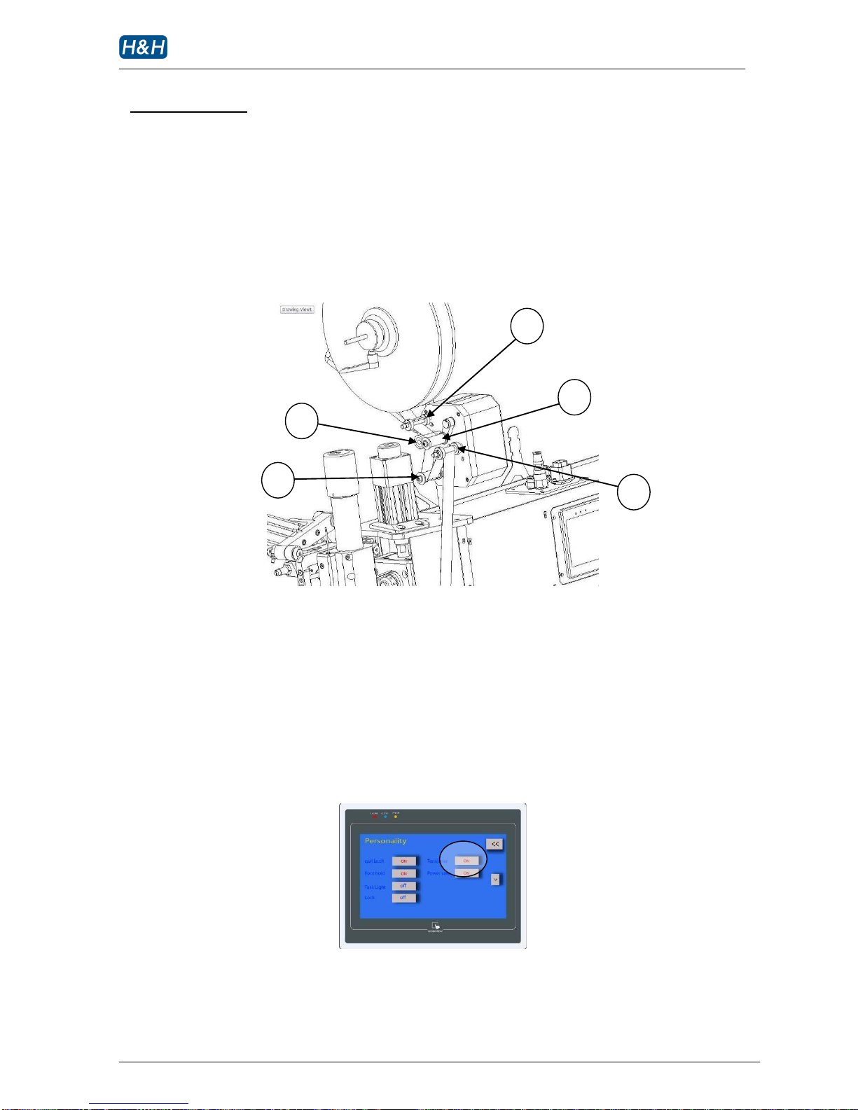
>> Digital Tensioner
During seam sealing, the consistent supply of seam tape to the sealing area is important. Your AI-007
is equipped with a built in digital tensioner to release the seam tape from the tape spool. Route the
tape exactly as shown in the below diagram.
1 drive roller
2 swing sensor
3 tape stabilizer
4 tensioner press roller
By default the tensioner is enabled and tape is dispensed while the machine is in operation. Press
the tensioner ON/OFF button in the personality page to enable/disable the tensioner.
1 2 3 4 3
Page 36
AI-007 operation manual
Issue 1 12.10.10, HMI version 13, plc version 29 P. 35 of 43
> Advance Operation (cont.)
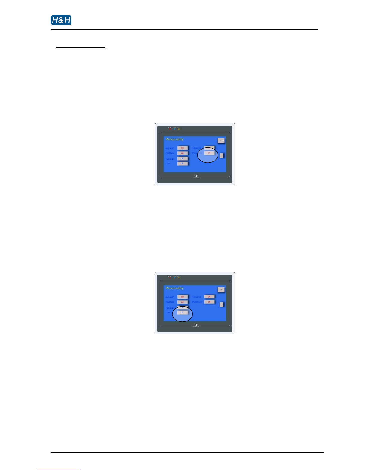
>> Power Save Mode
The heater consumes significant amount of electricity during operation. The Power save mode
enables the machine to turn off the heater after 10 minutes of idling, therefore reducing the
electricity cost.
>> Parameters Lock
The machine settings can be protected against accidental changes by the Parameters Lock
function. Press and hold the lock button in the personality page for 10 seconds to enable/disable
this function.
Page 37

AI-007 operation manual
Issue 1 12.10.10, HMI version 13, plc version 29 P. 36 of 43
> Maintenance
>> Preventative
In order to keep the machine in top running condition, regular maintenance is important for trouble
free operation. This will minimize possible down time and to prolong machine life.
Daily
Check the motion of the machine for smoothness and strange noise.
Check the air hoses for leakage or damage.
Check silicone roller for worn or damaged.
Weekly
Check all rollers for excessive play, all play should be less than 5 mm, adjust the
corresponding cam belt tension if necessary.
Lubricate the cutter blade slightly with machine oil. Wipe off any excessive oil if necessary.
While the machine is off and cooled, test the circuit breaker by pressing the test button.
The handle should flip to OFF immediately.
Check the speed of the nip roller cylinder. Adjust the speed by the air speed regulators
located under the touch screen control panel if necessary.
Visually inspect all the electrical and mechanical parts for abnormal burns and looseness.
Check the nozzle air pressure interlock: lower the nozzle air pressure gradually to below
0.05 Mpa, an alarm message should appear and the heater power will be cut off followed
by a drop in heater temperature.
Next increase the air pressure to above 0.1 Mpa, the alarm message ‘pressure low’ in the
page ‘main’ should disappear.
As Required
Clean the rollers to remove any adhesive residue, which may cause fabric wrapping.
Replace the silicone roller by a new one if necessary.
Replace heater element if damaged, be careful not to allow material being broken off from
the old element causing blockage to the air passages.
If nozzle is blocked, remove the nozzle from the heater and tap it gently to release foreign
material from the inlet side.
Page 38
AI-007 operation manual
Issue 1 12.10.10, HMI version 13, plc version 29 P. 37 of 43
> Maintenance (cont.)
>> Procedures for Replacing Parts
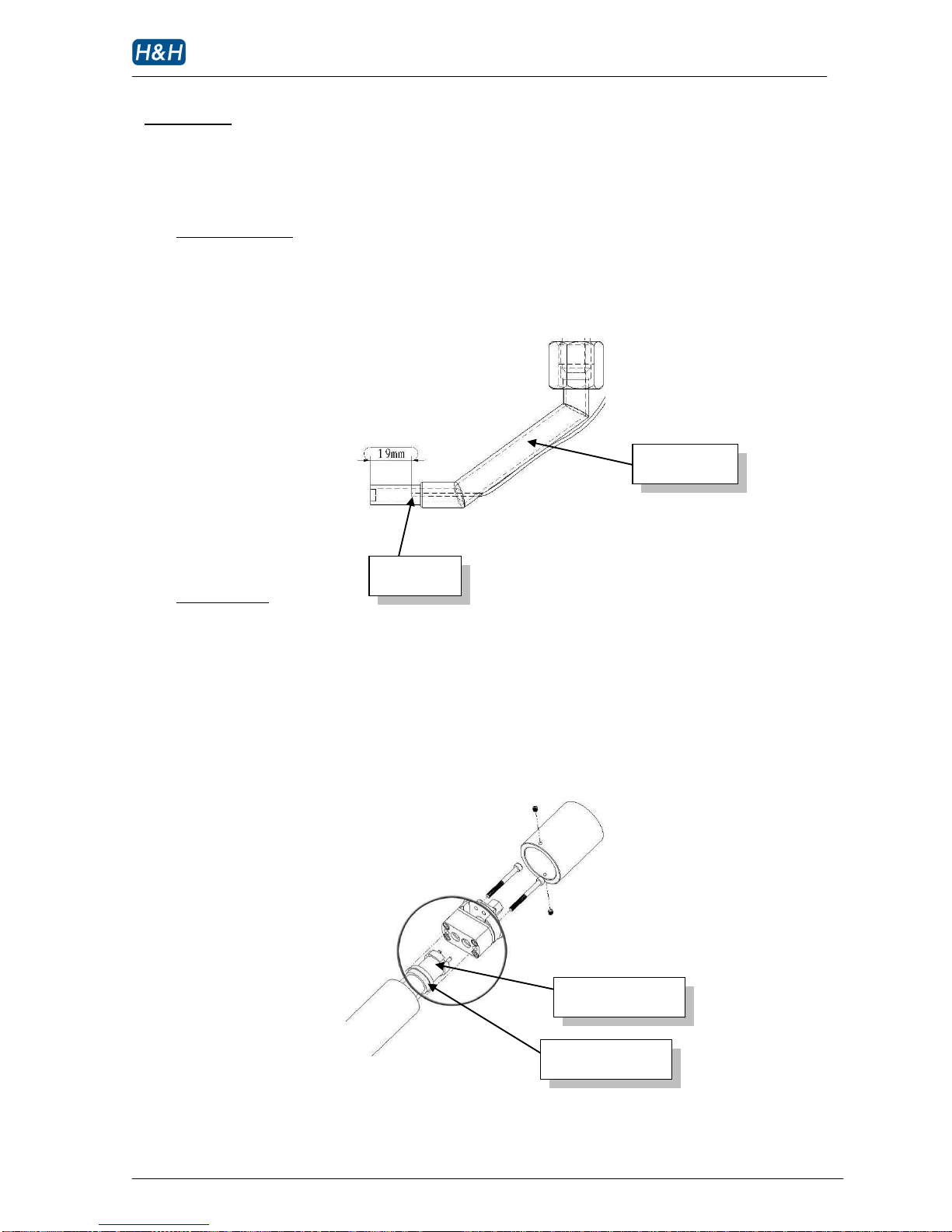
Temperature sensor
The tip of the replaced thermocouple is very important, the location must be the same as shown
in the below diagram. Also inspect and make sure that the tip is in the center of the pipe and not
touching the metal part. This is essential for the sensor to measure the air temperature correctly.
Heater Element
Remove the heater top cap and the heater securing mount to locate the heater element.
Carefully pull the element off the connecting sockets. Replace the broken element with a new
one, make sure that the red colored sealing gasket is installed properly. Installation is just the
reversal. After replacing a new heater element, run the machine at 300 C for at least 10 minutes
to break in the heater before operating at higher temperature.
heating element
nozzle pipe
Sensor tip
sealing gasket
Page 39
AI-007 operation manual
Issue 1 12.10.10, HMI version 13, plc version 29 P. 38 of 43
> Maintenance (cont.)
>> Procedures for Replacing Parts (cont.)
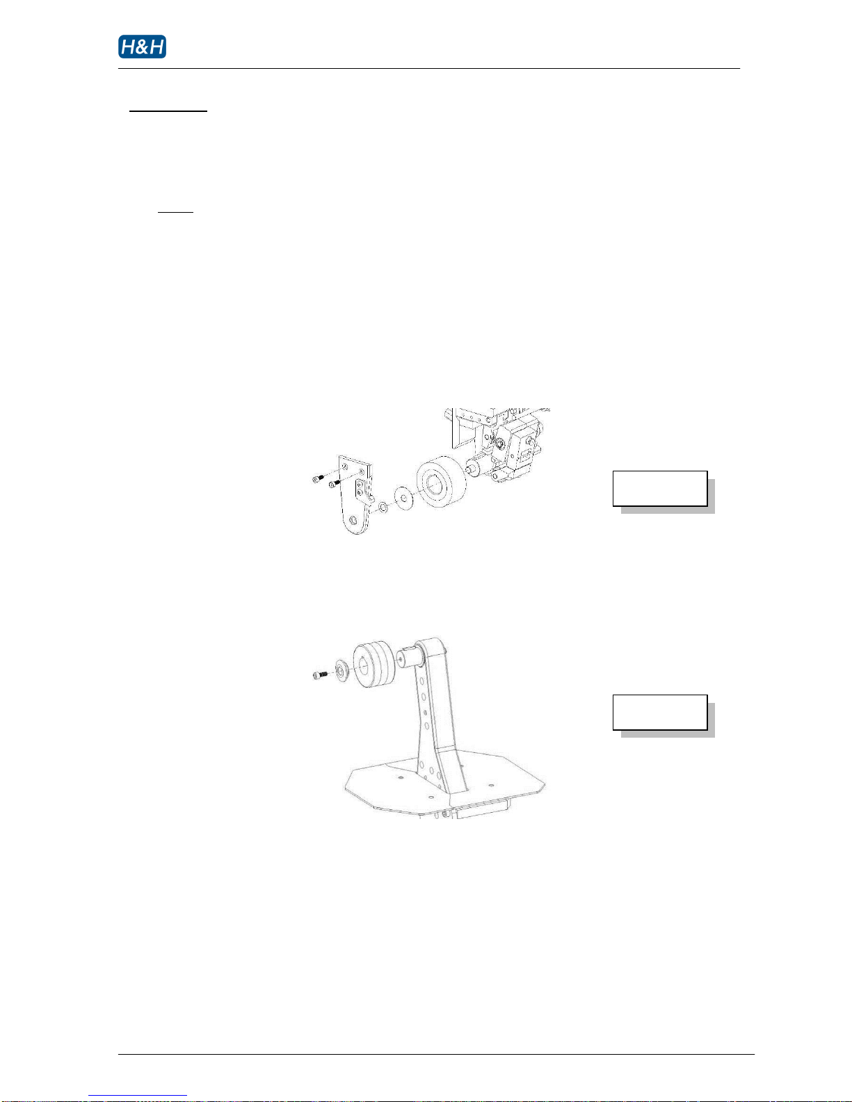
Rollers
The rollers are needed to be replaced when there are signs of torn or excessive worn in order to
maintain the consistence of quality of the finished product. Replace the rollers as shown in the
illustration below. Please choose the correct width and softness roller. For best result, always use
genuine H&H parts for replacement. Please contact us for optional sizes.
upper roller
lower roller
Page 40
AI-007 operation manual
Issue 1 12.10.10, HMI version 13, plc version 29 P. 39 of 43
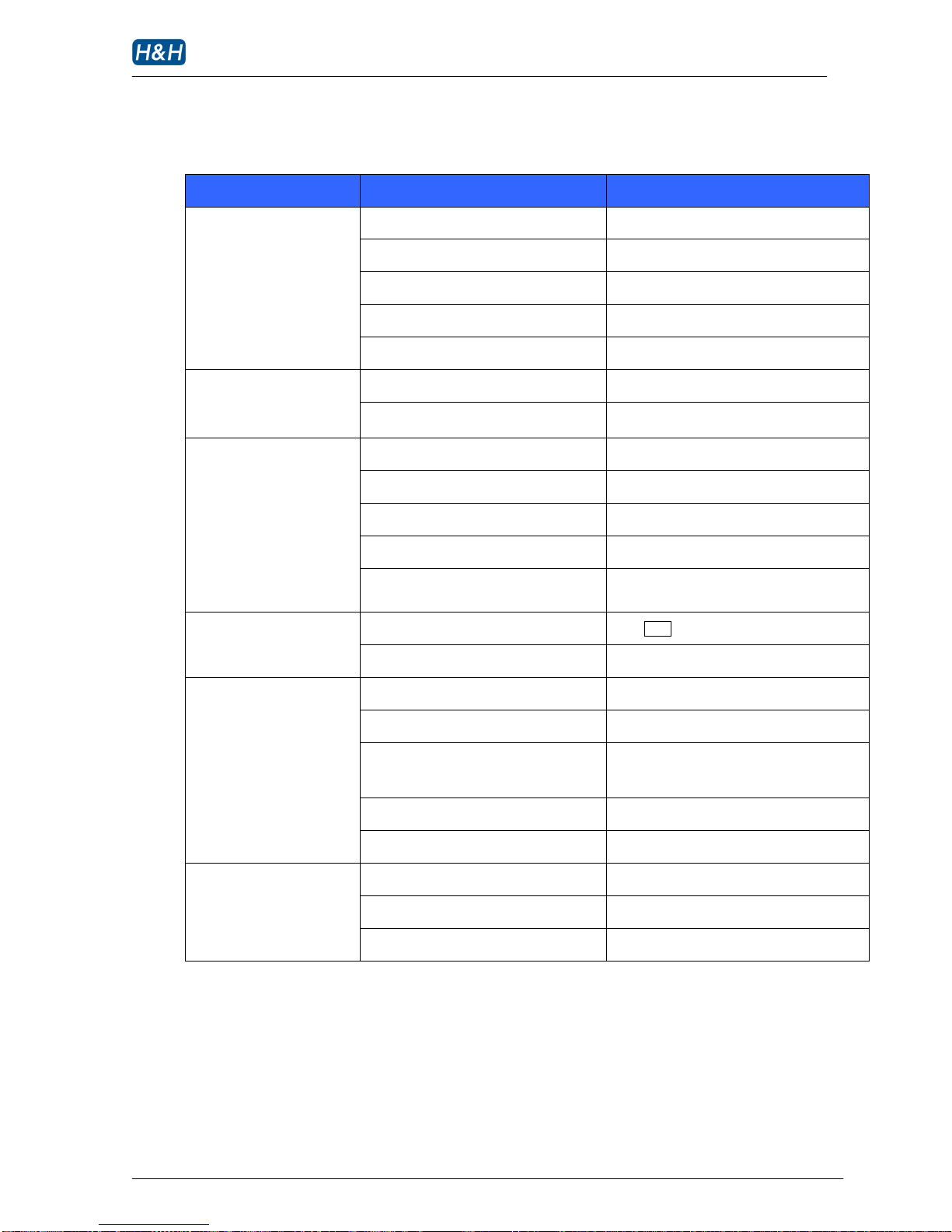
> Trouble Shooting
Problem
cause
solution
No power in some places
Power cable or plug faulty
Check the power supply connection
Circuit breaker tripped
Reset circuit breaker and investigate the cause
Main power switch not turned on
Press the power ON button (start)
Bad connection
Check all wires for loose connection
Faulty transformer
Check the voltage of switching power supply
Motor not turning
Nozzle in park position
Un-park the nozzle
Faulty Main controller
Replace a new controller
Temperature display not
stable
Faulty thermocouple
Replace a new temperature sensor
Loose thermocouple connection
Check and secure the connection
Faulty temperature controller
Replace PCB in the main electrical box
Thermocouple extension wire short circuit
Find the location and fix
Thermocouple not installed in proper
position
Check the position of sensor tip and fix
Temperature display Thermocouple extension wire short circuit
read ambient at all time
Heater is not turned on
Press HEAT to enable heater
Air pressure too low
Inspect if air supply is cut off
Temperature fluctuate
abnormally
Broken heater element
Replace heater element
Faulty thermocouple
Replace thermocouple
Hose tangled
Check for hose clearance or pinch during
heater movement
Line voltage fluctuation
Install voltage regulator
Loose object in air passage
Remove nozzle and clean the foreign material
Heater Not heating
Faulty solid state relay (SSR)
Replace solid state relay
Pressure low interlocked
Increase nozzle air pressure
Heater broken
Replace heater element
Page 41
AI-007 operation manual
Issue 1 12.10.10, HMI version 13, plc version 29 P. 40 of 43
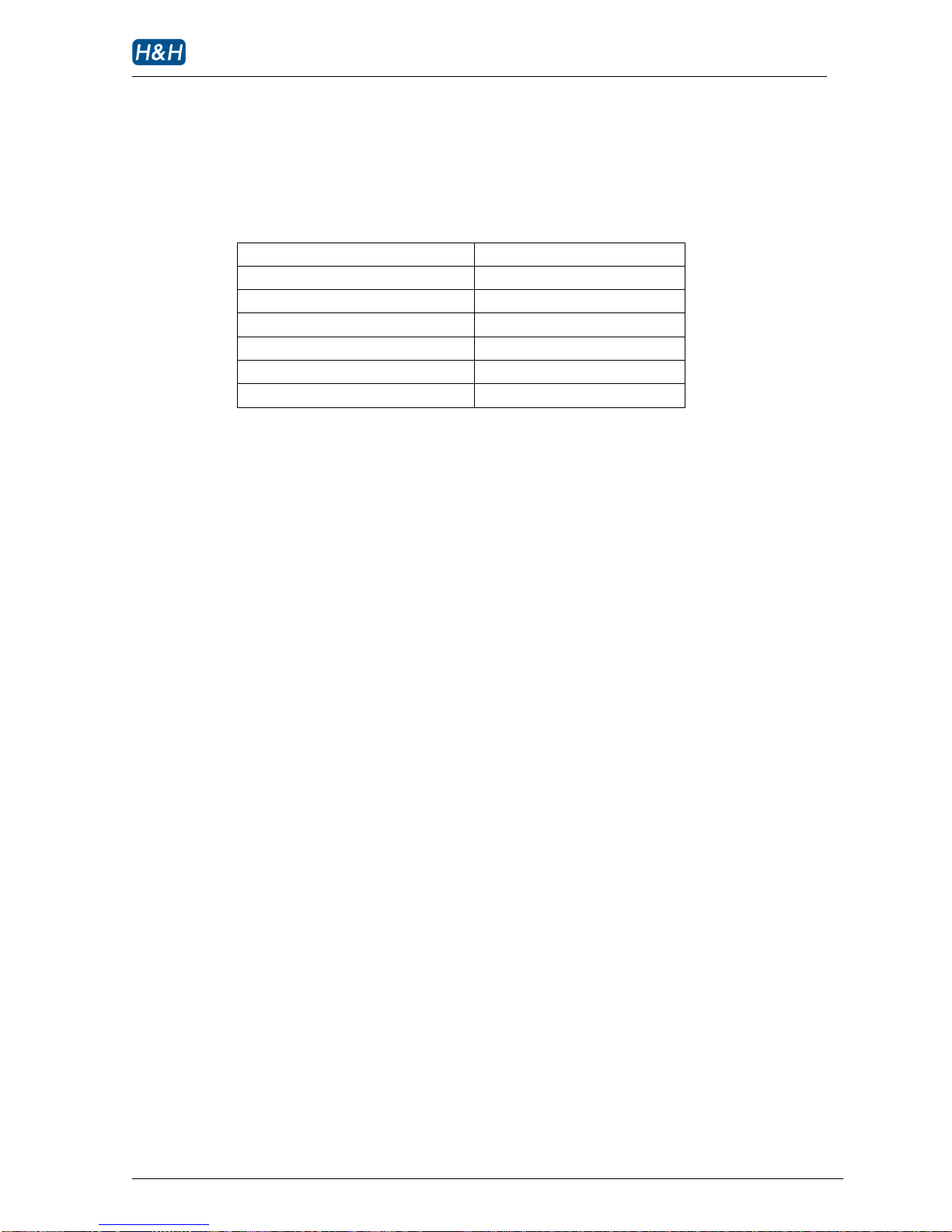
Appendix A Nozzle Air Flow Cross Reference Table
Nozzle air pressure (Mpa)
Air flow (L/min)
0.05
35
0.06
38
0.07
40
0.08
42
0.09
45
0.10
48
Page 42
AI-007 operation manual
Issue 1 12.10.10, HMI version 13, plc version 29 P. 41 of 43
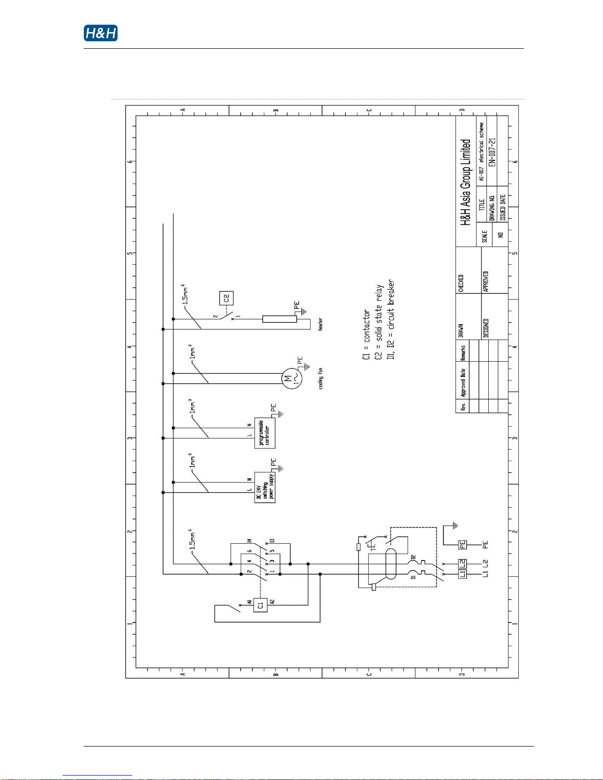
Appendix B Electrical Scheme
Page 43
AI-007 operation manual
Issue 1 12.10.10, HMI version 13, plc version 29 P. 42 of 43
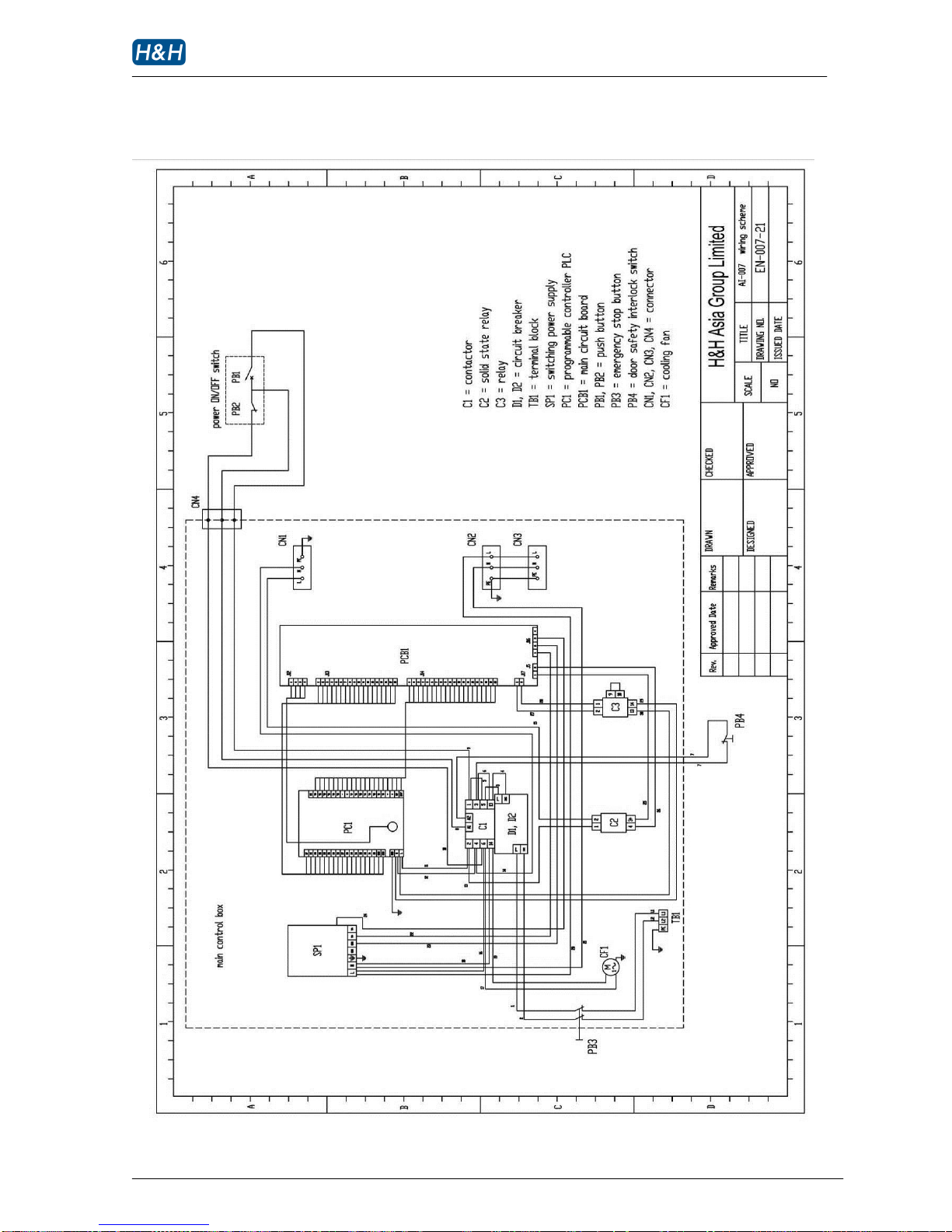
Appendix C Wiring Scheme
Page 44
AI-007 operation manual
Issue 1 12.10.10, HMI version 13, plc version 29 P. 43 of 43
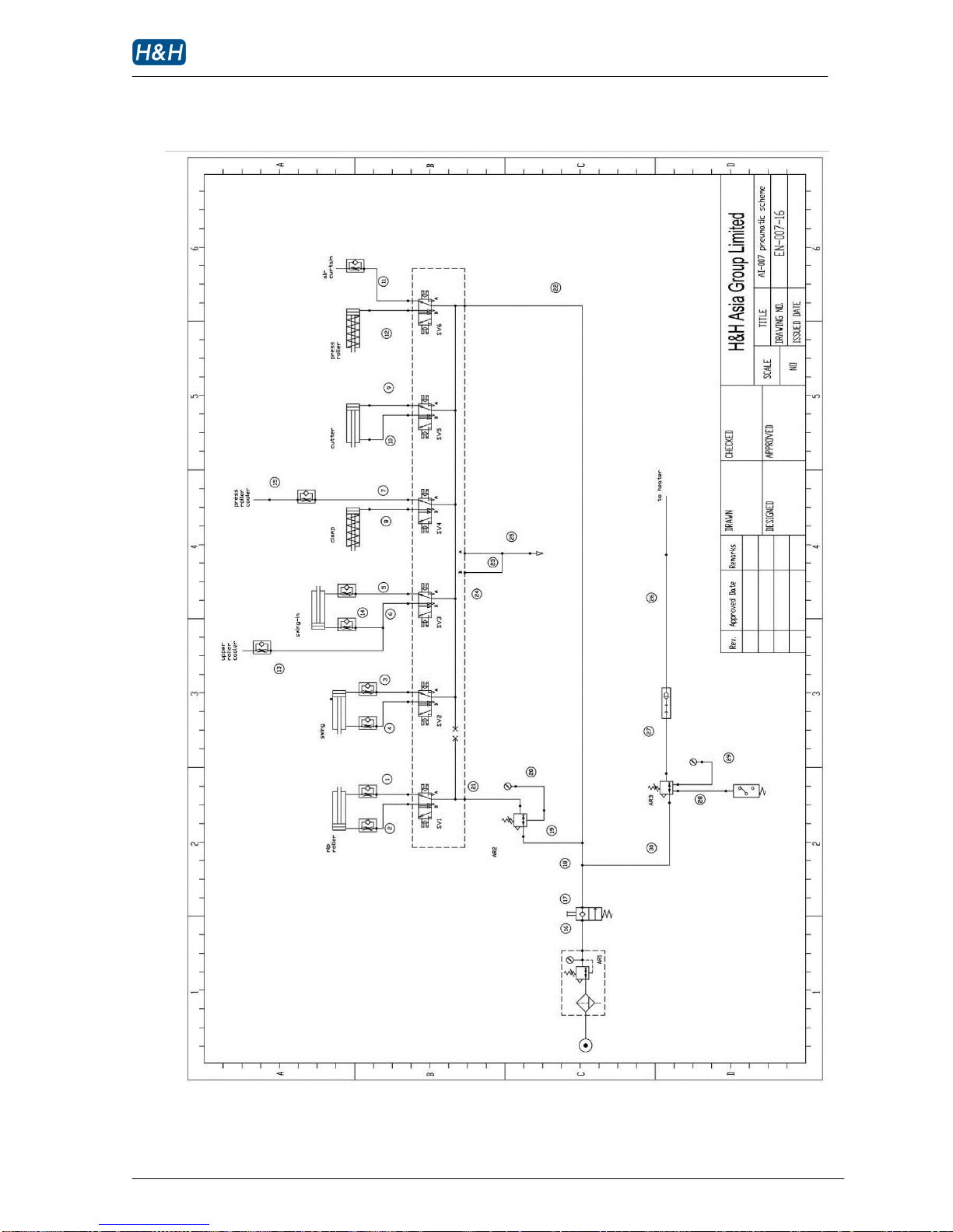
Appendix D Pneumatic Scheme
 Loading...