

Page 1
Model:
HUS726060AL5210/1/4/5
HUS726050AL5210/1/4/5
HUS726040AL5210/1/4/5
HUS726020AL5210/1/4/5
HUS726060AL4210/1/4/5
HUS726050AL4210/1/4/5
HUS726040AL4210/1/4/5
HUS726020AL4210/1/4/5
Hard disk drive specifications
HGST Ultrastar 7K6000
3.5 inch Serial Attached SCSI hard disk drive
Revision 1.6 23 May 2016
1
HGST Hard Disk Drive OEM Specification
Page 2

Revision 1.6 (23 May 2016)
The following paragraph does not apply to the United Kingdom or any country where such provisions are
inconsistent with local law: HGST a Western Digital company PROVIDES THIS PUBLICATION "AS IS"
WITHOUT WARRANTY OF ANY KIND, EITHER EXPRESS OR IMPLIED, INCLUDING, BUT NOT
LIMITED TO, THE IMPLIED WARRANTIES OF MERCHANTABILITY OR FITNESS FOR A
PARTICULAR PURPOSE. Some states do not allow disclaimer or express or implied warranties in certain
transactions, therefore, this statement may not apply to you.
This publication could include technical inaccuracies or typographical errors. Changes are periodically
made to the information herein; these changes will be incorporated in new editions of the publication.
HGST may make improvements or changes in any products or programs described in this publication at
any time.
It is possible that this publication may contain reference to, or information about, HGST products
(machines and programs), programming, or services that are not announced in your country. Such
references or information must not be construed to mean that HGST intends to announce such HGST
products, programming, or services in your country.
Technical information about this product is available by contacting your local HGST representative or on
the Internet at www.hgst.com/support,
HGST may have patents or pending patent applications covering subject matter in this document. The
furnishing of this document does not give you any license to these patents.
© 2015 HGST, Inc. All rights reserved.
HGST, a Western Digital company
3403 Yerba Buena Road
San Jose, CA 95135
Produced in the United States
05/16
Ultrastar™ is a trademark of HGST, Inc. and its affiliates in the United States and/or other countries.
HGST trademarks are authorized for use in countries and jurisdictions in which HGST has the right to
use, market and advertise the brands.
Other product names are trademarks or registered trademarks of their respective owners.
One GB is equal to one billion bytes and one TB equals 1,000 GB (one trillion bytes) when referring to hard
drive capacity. Accessible capacity will vary from the stated capacity due to formatting and partitioning of
the hard drive, the computer’s operating system, and other factors.
References in this publication to HGST products, programs or services do not imply that HGST intends to
make these available in all countries in which HGST operates.
Product information is provided for information purposes only and does not constitute a warranty.
Information is true as of the date of publication and is subject to change. Actual results may vary. This
publication is for general guidance only. Photographs may show design models.
23 May 2016
2
HGST Hard Disk Drive OEM Specification
Page 3
Table of contents
1 General ................................................................................................................................................................ 18
Introduction .............................................................................................................................. 18
Glossary ..................................................................................................................................... 19
General caution ......................................................................................................................... 19
References ................................................................................................................................. 19
2 General features .................................................................................................................................................. 20
Part 1. Functional specification ....................................................................................................................... 21
3 Fixed disk subsystem description ........................................................................................................................ 22
Control Electronics ................................................................................................................... 22
Head disk assembly .................................................................................................................. 22
Actuator ..................................................................................................................................... 22
4 Drive characteristics ............................................................................................................................................ 23
Default logical drive parameters ............................................................................................. 23
Data sheet ................................................................................................................................. 26
World Wide Name Assignment ................................................................................................ 26
Drive organization .................................................................................................................... 26
Drive Format ............................................................................................................................. 26
Cylinder allocation ................................................................................................................... 26
Performance characteristics .................................................................................................... 27
Mechanical positioning............................................................................................................. 27
Drive ready time ....................................................................................................................... 28
Operating modes ....................................................................................................................... 28
5 Defect flagging strategy ....................................................................................................................................... 29
Shipped format ......................................................................................................................... 29
6 Specification ........................................................................................................................................................ 30
Electrical interface ................................................................................................................... 30
Connector location .................................................................................................................... 30
29 pin Serial Attached SCSI (SAS) Connector Definition ..................................................... 31
Voltage and Ground Signals .................................................................................................... 32
Ready LED output .................................................................................................................... 32
Environment ............................................................................................................................. 33
Temperature and humidity ...................................................................................................... 33
Corrosion test ............................................................................................................................ 34
Atmospheric condition .............................................................................................................. 34
DC power requirements ........................................................................................................... 35
Input voltage ............................................................................................................................. 35
Power supply current (typical1) ............................................................................................... 36
Power supply generated ripple at drive power connector...................................................... 38
Power Consumption Efficiency ................................................................................................ 38
Reliability .................................................................................................................................. 39
Data integrity............................................................................................................................ 39
Cable noise interference ........................................................................................................... 39
Load/Unload .............................................................................................................................. 39
Start/stop cycles ........................................................................................................................ 39
Preventive maintenance........................................................................................................... 39
Data reliability .......................................................................................................................... 39
Required Power-Off Sequence ................................................................................................. 39
Mechanical specifications......................................................................................................... 40
Physical dimensions ................................................................................................................. 40
Connector locations .................................................................................................................. 44
Drive mounting ......................................................................................................................... 44
Heads unload and actuator lock .............................................................................................. 44
3
HGST Hard Disk Drive OEM Specification
Page 4
Vibration and shock .................................................................................................................. 45
Operating vibration .................................................................................................................. 45
Nonoperating vibration ............................................................................................................ 46
Operating shock ........................................................................................................................ 46
Nonoperating shock .................................................................................................................. 46
Nonoperating Rotational shock ............................................................................................... 47
Acoustics .................................................................................................................................... 48
Identification labels .................................................................................................................. 48
Safety ......................................................................................................................................... 49
UL and CSA standard conformity ........................................................................................... 49
German Safety Mark ................................................................................................................ 49
Flammability ............................................................................................................................. 49
Safe handling ............................................................................................................................ 49
Substance restriction requirements ........................................................................................ 49
Secondary circuit protection .................................................................................................... 49
Electromagnetic compatibility ................................................................................................. 50
CE Mark .................................................................................................................................... 50
C-Tick Mark .............................................................................................................................. 50
BSMI Mark ............................................................................................................................... 50
KC Mark .................................................................................................................................... 50
Part 2. Interface specification .......................................................................................................................... 51
7 SAS Attachment .................................................................................................................................................. 52
General ...................................................................................................................................... 52
SAS Features ............................................................................................................................ 52
SAS Names and Identifiers...................................................................................................... 54
Layer .......................................................................................................................................... 56
Link Reset Sequence ................................................................................................................ 56
Hard Reset ................................................................................................................................ 56
SAS OOB (Out of Band) ........................................................................................................... 57
SAS Speed Negotiation ............................................................................................................ 57
PHY Error Handling ................................................................................................................ 58
Link Layer ................................................................................................................................. 59
Address Frames ........................................................................................................................ 59
Link Layer Error Handling...................................................................................................... 62
Transport Layer ........................................................................................................................ 64
Command Information Unit .................................................................................................... 65
TASK Information Units .......................................................................................................... 66
XFER_RDY Information Units ................................................................................................ 67
DATA Information Units .......................................................................................................... 67
RESPONSE Information Units ............................................................................................... 68
Sequences of SSP Information Units ...................................................................................... 70
Transport Layer Error Handling ............................................................................................. 71
8 SCSI Command Set ............................................................................................................................................ 72
SCSI Control Byte .................................................................................................................... 74
Abbreviations ............................................................................................................................ 74
Byte ordering conventions ....................................................................................................... 74
FORMAT UNIT (04) ................................................................................................................. 75
Parameter List Header ............................................................................................................ 77
Initialization Pattern ............................................................................................................... 79
Defect Descriptor ...................................................................................................................... 81
INQUIRY (12) ........................................................................................................................... 83
Inquiry Data .............................................................................................................................. 84
LOG SELECT (4C) ................................................................................................................... 99
LOG SENSE (4D) ................................................................................................................... 102
Log Page Parameters ............................................................................................................. 103
4
HGST Hard Disk Drive OEM Specification
Page 5
Log Sense Page 0 .................................................................................................................... 104
Log Sense Page 2 .................................................................................................................... 105
Log Sense Page 3 .................................................................................................................... 106
Log Sense Page 5 .................................................................................................................... 107
Log Sense Page 6 .................................................................................................................... 108
Log Sense Page D ................................................................................................................... 108
Log Sense Page E .................................................................................................................... 109
Log Sense Page F ..................................................................................................................... 110
Log Sense Page 10 ................................................................................................................... 111
Log Sense Page 15 ................................................................................................................... 113
Log Sense Page 18 ................................................................................................................... 115
Log Sense Page 19h - General Statistics and Performance ................................................. 119
Log Sense Page 1A .................................................................................................................. 121
Log Sense Page 2F .................................................................................................................. 122
Log Sense Page 30 .................................................................................................................. 122
Log Sense Page 37 .................................................................................................................. 125
MODE SELECT (15) .............................................................................................................. 126
MODE SELECT (55) .............................................................................................................. 127
MODE SENSE (1A) ................................................................................................................ 128
Mode Parameter List .............................................................................................................. 130
Mode Page 00 (Vendor Unique Parameters) ......................................................................... 133
Mode Page 01 (Read/Write Error Recovery Parameters) .................................................... 135
Mode Page 02 (Disconnect/Reconnect Parameters) ............................................................. 139
Mode Page 03 (Format Device Parameters) ......................................................................... 140
Mode Page 04 (Rigid Disk Drive Geometry Parameters) .................................................... 141
Mode Page 07 (Verify Error Recovery Parameters) ............................................................. 142
Mode Page 08 (Caching Parameters) .................................................................................... 143
Mode Page 0A (Control Mode Page Parameters) ................................................................. 145
Mode Page 0C (Notch Parameters) ....................................................................................... 149
Mode Page 18h ........................................................................................................................ 150
Mode Page 19h (Port Control Parameters) ........................................................................... 151
Mode Page 1A (Power Control) .............................................................................................. 156
Mode Page 1C (Informational Exceptions Control) ............................................................. 158
MODE SENSE (5A) ................................................................................................................ 161
PERSISTENT RESERVE IN (5E) ......................................................................................... 162
Service Action .......................................................................................................................... 162
Parameter data for Read Keys .............................................................................................. 163
Parameter Data for Read Reservations ................................................................................ 164
PERSISTENT RESERVE OUT (5F) ..................................................................................... 165
Service Action .......................................................................................................................... 165
Type ......................................................................................................................................... 166
Parameter list ......................................................................................................................... 167
Summary ................................................................................................................................. 168
PRE-FETCH (34) .................................................................................................................... 169
PRE-FETCH (90) .................................................................................................................... 170
READ (6) - (08) ........................................................................................................................ 171
READ (10) - (28) ...................................................................................................................... 172
READ (12) - (A8) ..................................................................................................................... 174
READ (16) - (88) ...................................................................................................................... 175
READ (32) - (7F/09) ................................................................................................................ 176
READ BUFFER (3C) .............................................................................................................. 177
Combined Header And Data (Mode 00000b) ........................................................................ 177
Read Data (Mode 00010b) ...................................................................................................... 178
Descriptor (Mode 00011b) ...................................................................................................... 178
5
HGST Hard Disk Drive OEM Specification
Page 6
Read Data from Echo Buffer (Mode 01010b) ........................................................................ 178
Echo Buffer Descriptor (Mode 01011b) ................................................................................. 179
Expander Communications and Echo Buffer (Mode 11010b) .............................................. 179
Error History (Mode 11100b) ................................................................................................. 179
READ CAPACITY (10) - (25) ................................................................................................. 182
Returned Data Format ........................................................................................................... 182
READ CAPACITY (16) (9E/10) .............................................................................................. 183
Returned Data Format ........................................................................................................... 183
READ DEFECT DATA (37) .................................................................................................... 184
Defect List Header .................................................................................................................. 185
Defect List Descriptor ............................................................................................................ 185
Bytes from Index Format (100b) ........................................................................................... 185
Physical Sector Format (101b) ............................................................................................... 186
READ DEFECT DATA (B7) ................................................................................................... 187
Defect List Header .................................................................................................................. 187
Defect List Descriptor ............................................................................................................ 187
Bytes from Index Format (100b) ........................................................................................... 188
Physical Sector Format (101b) ............................................................................................... 188
READ LONG (3E) ................................................................................................................... 189
READ LONG (9E) ................................................................................................................... 190
REASSIGN BLOCKS (07) ...................................................................................................... 191
RECEIVE DIAGNOSTICS RESULTS (1C) .......................................................................... 192
Receive Diagnostic Results Page 0 ........................................................................................ 192
Receive Diagnostic Results Page 40 ...................................................................................... 193
RELEASE (17) ........................................................................................................................ 194
RELEASE (57) ........................................................................................................................ 195
REPORT DEVICE IDENTIFIER (A3/05) ............................................................................. 196
REPORT LUNS (A0) .............................................................................................................. 197
REPORT SUPPORTED OPERATION CODES (A3/0C) ...................................................... 198
All_commands parameter data format ................................................................................. 199
One_command parameter data format ................................................................................. 200
Command timeouts descriptor format .................................................................................. 201
REPORT SUPPORTED TASK MANAGEMENT FUNCTIONS (A3/0D) ........................... 203
REPORT TIMESTAMP (A3/0F) ............................................................................................ 205
Device clocks and timestamps ............................................................................................... 206
REQUEST SENSE (03) .......................................................................................................... 207
RESERVE (16) ........................................................................................................................ 208
RESERVE (56) ........................................................................................................................ 209
REZERO UNIT (01) ................................................................................................................ 210
SANITIZE (48) ......................................................................................................................... 211
Sanitize (48) Service Action Codes ......................................................................................... 211
SECURITY PROTOCOL IN (A2) .......................................................................................... 213
SECURITY PROTOCOL OUT (B5) ...................................................................................... 214
SEND DIAGNOSTIC (1D) ..................................................................................................... 215
Send Diagnostic Page 0 .......................................................................................................... 216
Send Diagnostic Page 3F ....................................................................................................... 216
Send Diagnostic Page 40 ........................................................................................................ 218
SET DEVICE IDENTIFIER (A4/06) ..................................................................................... 220
SET TIMESTAMP (A4/0F) ..................................................................................................... 221
START STOP UNIT (1B) ....................................................................................................... 222
SYNCHRONIZE CACHE (10) - (35) ..................................................................................... 224
SYNCHRONIZE CACHE (16) - (91) ..................................................................................... 225
TEST UNIT READY (00) ....................................................................................................... 226
VERIFY (10) - (2F) .................................................................................................................. 227
6
HGST Hard Disk Drive OEM Specification
Page 7
VERIFY (12) - (AF) ................................................................................................................. 229
VERIFY (16) - (8F) .................................................................................................................. 230
VERIFY (32) - (7F/0A) ............................................................................................................ 231
WRITE (6) - (0A) ..................................................................................................................... 232
WRITE (10) - (2A) ................................................................................................................... 233
WRITE (12) - (AA) .................................................................................................................. 235
WRITE (16) - (8A) ................................................................................................................... 236
WRITE (32) - (7F/0B).............................................................................................................. 237
WRITE AND VERIFY (10) - (2E) .......................................................................................... 238
WRITE AND VERIFY (12) - (AE) .......................................................................................... 239
WRITE AND VERIFY (16) - (8E) .......................................................................................... 240
WRITE AND VERIFY (32) - (7F/0C) ..................................................................................... 241
WRITE BUFFER (3B) ............................................................................................................ 242
Combined Header And Data (Mode 00000b) ........................................................................ 243
Write Data (Mode 00010b) ..................................................................................................... 243
Download Microcode (Mode 00100b) ..................................................................................... 243
Download Microcode and Save (Mode 00101b) -Single Binary File ................................... 244
Download Microcode and Save (Mode 00111b) - Multiple Binary Files ............................. 244
Write Data to Echo Buffer (Mode 01010b) ............................................................................ 244
Download Microcode with Offsets, Select Activation Events, Save, and Defer Activate (Mode
01101b) .................................................................................................................................... 245
Download Microcode with Offsets, Save, and Defer Activate (Mode 01110b) .................... 245
Activate Deferred Microcode Mode (Mode 01111b) .............................................................. 245
Enable Expander Communications Protocol (Mode 11010b) .............................................. 245
WRITE LONG (10) (3F) ....................................................................................................... 246
WRITE LONG (16) - (9F) ....................................................................................................... 248
WRITE SAME (10) - (41) ........................................................................................................ 249
WRITE SAME (16) - (93) ........................................................................................................ 250
WRITE SAME (32) - (7F/0D) ................................................................................................. 251
9 SCSI Status Byte ............................................................................................................................................... 252
10 Additional information ...................................................................................................................... 253
SCSI Protocol .......................................................................................................................... 253
Priority of SCSI Status Byte Reporting ................................................................................ 253
Invalid LUN Processing ......................................................................................................... 253
Overlapped Commands .......................................................................................................... 253
Command Processing During Execution of Active I/O Process ........................................... 254
Unit Attention Condition ....................................................................................................... 255
Command Processing During Startup and Format Operations ......................................... 256
Internal Error Condition ........................................................................................................ 256
Deferred Error Condition ....................................................................................................... 256
Degraded Mode ....................................................................................................................... 257
Command Processing while Reserved ................................................................................... 260
Priority Commands ................................................................................................................ 261
Command Queuing ................................................................................................................. 261
Queue Depth ........................................................................................................................... 261
Queue Full Status ................................................................................................................... 261
Termination of I/O Processes ................................................................................................. 261
Command Reordering ............................................................................................................ 262
Concurrent I/O Process .......................................................................................................... 262
Write Cache ............................................................................................................................. 262
Automatic Rewrite/Reallocate ............................................................................................... 262
Segmented Caching ................................................................................................................ 264
Overview .................................................................................................................................. 264
Read Ahead ............................................................................................................................. 264
Multiple Initiator Systems ..................................................................................................... 264
7
HGST Hard Disk Drive OEM Specification
Page 8
Sense Data .............................................................................................................................. 264
Mode Pages ............................................................................................................................. 264
Multiple Initiator Environment ............................................................................................ 265
Initiator Sense Data ............................................................................................................... 265
Initiator Mode Select/Mode Sense Parameters .................................................................... 265
Reset ........................................................................................................................................ 265
Initiator Sense Data ............................................................................................................... 265
Reset Actions ........................................................................................................................... 265
Diagnostics .............................................................................................................................. 266
Power on Diagnostics ............................................................................................................. 266
Self-test via SEND DIAGNOSTIC Command ...................................................................... 266
Idle Time Function ................................................................................................................. 269
Command Time out Limits .................................................................................................... 269
Reassignment Time ................................................................................................................ 269
Format Time ........................................................................................................................... 269
Start/Stop Unit Time .............................................................................................................. 269
Medium Access Command Time ............................................................................................ 269
Time-out Limits for Other Commands .................................................................................. 270
Recommended Initiator ERP ................................................................................................. 271
Drive Service Strategy ........................................................................................................... 271
Recommendations for System Error Log .............................................................................. 271
Data Recovery Procedure ....................................................................................................... 272
Non data Error Recovery Procedure ..................................................................................... 273
RAID Rebuild Assist ............................................................................................................... 279
Rebuild Assist diagnostic page .............................................................................................. 279
11 Firmware Security .............................................................................................................................................. 281
Referenced Specifications and Standards ............................................................................. 281
TCG Specifications ................................................................................................................. 281
Federal Information Processing Standards (FIPS) .............................................................. 281
National Institute of Standards and Technology (NIST) ..................................................... 282
Department of Defense........................................................................................................... 282
RSA Laboratories Standards ................................................................................................. 282
Other Standards ..................................................................................................................... 282
Implementation Exceptions ................................................................................................... 283
Implementation Features and Details Outside of TCG Specifications .............................. 283
Encryption Algorithms ........................................................................................................... 284
Advanced Encryption Standard (AES) Support ................................................................... 284
‘Level 0 Discovery’ Vendor Specific Data .............................................................................. 284
Deterministic Random Bit Generation (DRBG) ................................................................... 285
Key Wrap ................................................................................................................................. 285
Key Erasure ............................................................................................................................ 285
TCG SSC Tables ..................................................................................................................... 286
‘Admin SP’ C_PIN and ‘Locking SP’ C_PIN Tables .............................................................. 286
K_AES_256 Table ................................................................................................................... 286
‘Locking SP’ Access Control Table ......................................................................................... 287
‘Locking Info’ Table ................................................................................................................. 287
‘Locking SP’ Locking Table ..................................................................................................... 287
Firmware Download and Signing .......................................................................................... 288
Revert Feature ........................................................................................................................ 288
Ports ......................................................................................................................................... 289
MSID........................................................................................................................................ 292
Logging .................................................................................................................................... 292
Number of Sessions ................................................................................................................ 292
Number of Bands .................................................................................................................... 292
8
HGST Hard Disk Drive OEM Specification
Page 9
Number of COMIDs ................................................................................................................ 292
Locked and Unlocked Behavior ............................................................................................. 293
T10 SCSI Commands ............................................................................................................. 293
TCG SSC Commands ............................................................................................................. 295
Error Codes ............................................................................................................................. 297
Customer Specific Requirements .......................................................................................... 297
FIPS140 Cryptographic Officer Instructions ....................................................................... 298
Physical Security .................................................................................................................... 298
Security Protocol Parameters ................................................................................................ 298
Certified Models, Hardware Versions and Firmware Versions ........................................... 303
Cryptographic Module Acceptance and Provisioning .......................................................... 303
Zeroization of the Cryptographic Module ............................................................................. 303
12 SCSI Sense Data ............................................................................................................................ 304
SCSI Sense Data Format Introduction ................................................................................. 304
Sense Data Format ................................................................................................................. 304
Sense Data Length ................................................................................................................. 304
Sense Data Response Code .................................................................................................... 304
Fixed Format Sense Data ...................................................................................................... 305
Valid (Bit 7 of byte 0) .............................................................................................................. 305
Response Code (Bit 6 - 0 of byte 0) ........................................................................................ 305
ILI: Incorrect Length Indicator (Bit 5 of byte 2) .................................................................. 305
Sense Key (Bit 3 - 0 of byte 2) ................................................................................................ 306
Information Bytes (Byte 3 through 6) ................................................................................... 307
Additional Sense Length (Byte 7) ......................................................................................... 307
Command Specific Information (Byte 8 through 11) ........................................................... 307
Additional Sense Code/Qualifier (Byte 12 and 13) ............................................................... 308
FRU: Field Replaceable Unit (Byte 14)................................................................................. 330
Sense Key Specific (Byte 15 through 17) .............................................................................. 330
Reserved (Byte 18 through 19)h ............................................................................................ 332
Vendor unique error information (Byte 20 through 23) ....................................................... 332
Physical Error Record (Product Specific Information) (Byte 24 through 29)..................... 332
Descriptor Format Sense Data .............................................................................................. 333
Order of Sense Descriptors .................................................................................................... 334
Sense Data Descriptor Definitions ........................................................................................ 335
13 Appendix. UEC list........................................................................................................................... 339
9
HGST Hard Disk Drive OEM Specification
Page 10

List of tables
Table 1 Type and Model# ........................................................................................................................ 18
Table 2 Formatted capacity .................................................................................................................... 25
Table 3 Mechanical positioning performance ........................................................................................ 26
Table 4 World Wide Name Assignment ................................................................................................. 26
Table 5 Average seek time ...................................................................................................................... 27
Table 6 Single Track Seek Time ............................................................................................................. 27
Table 7 Latency Time .............................................................................................................................. 27
Table 8 Drive ready time ........................................................................................................................ 28
Table 9 Mode transition times ................................................................................................................ 28
Table 10 29-pin Connector Signal Definition ........................................................................................ 31
Table 11 Temperature and humidity ..................................................................................................... 33
Table 12 Input voltage ............................................................................................................................ 35
Table 13 SAS power consumption (6TB/5TB/4TB Model) .................................................................... 36
Table 14 SAS power consumption (2TB Model) .................................................................................... 37
Table 15 Power supply generated ripple at drive power connector ..................................................... 38
Table 16 Power Consumption Efficiency ............................................................................................... 38
Table 17 Physical Dimensions ................................................................................................................ 43
Table 18 Random vibration PSD profile break points (operating) ...................................................... 45
Table 19 Random vibration (Rotational) PSD profile break points ..................................................... 45
Table 20 Random vibration PSD profile break points (nonoperating) ................................................ 46
Table 21 Sinusoidal shock wave ............................................................................................................. 46
Table 22 Rotational Shock ...................................................................................................................... 47
Table 23 Sound power levels .................................................................................................................. 48
Table 24 Names and Identifiers ............................................................................................................. 54
Table 25 SAS Address Format ................................................................................................................ 54
Table 26 IEEE Registered Name Format .............................................................................................. 54
Table 27 Name Address Authority field ................................................................................................. 55
Table 28 SAS Speed Negotiation ............................................................................................................ 57
Table 29 Supported Settings Bit Priorities ........................................................................................... 58
Table 30 PHY Layer Error Handling ..................................................................................................... 58
Table 31 Address Frame Format............................................................................................................ 59
Table 32 Frame Type: .............................................................................................................................. 59
Table 33 Identify Address Frame ........................................................................................................... 59
Table 34 Reason Field ............................................................................................................................. 60
Table 35 Open Address Frame Format .................................................................................................. 61
Table 36 Link Layer Error Handling (part 1 of 2) ................................................................................ 62
Table 37 Link Layer Error Handling (part 2 of 2) ................................................................................ 63
Table 38 SAS Frame Format .................................................................................................................. 64
Table 39 FRAME TYPE Field ................................................................................................................ 64
Table 40 COMMAND Information Unit ................................................................................................ 65
Table 41 Task Attribute Field ................................................................................................................. 65
Table 42 TASK Information Unit ........................................................................................................... 66
Table 43 TASK MANAGEMENT FUNCTION Field ............................................................................ 66
Table 44 Additional Response Information Argument for Query Async Event .................................. 67
Table 45 UADE DEPTH Field ................................................................................................................ 67
Table 46 XFER_RDY Information Units ............................................................................................... 67
Table 47 Data Information Unit ............................................................................................................. 67
Table 48 Response Information Unit ..................................................................................................... 68
Table 49 RETRY DELAY TIMER Field ................................................................................................. 68
Table 50 DATAPRES Field ..................................................................................................................... 69
Table 51 RESPONSE Data ..................................................................................................................... 69
10
HGST Hard Disk Drive OEM Specification
Page 11

Table 52 RESPONSE Codes ................................................................................................................... 69
Table 53 Transport Layer Error Handling ............................................................................................ 71
Table 54 SCSI Commands Supported (part 1 of 2) ............................................................................... 72
Table 55 SCSI Commands Supported (part 2 of 2) ............................................................................... 73
Table 56 SCSI Control Byte .................................................................................................................... 74
Table 57 FORMAT UNIT ........................................................................................................................ 75
Table 58 Format of the Short Parameter List Header ......................................................................... 77
Table 59 Format of the Long Parameter List Header .......................................................................... 77
Table 60 Format of the Long Parameter List Header .......................................................................... 77
Table 61 Data Format with Protection field .......................................................................................... 78
Table 62 Initialization Pattern Descriptor ............................................................................................ 79
Table 63 Defect Descriptor - Block Format (for n + 1 defects) ............................................................. 81
Table 64 Defect Descriptor - Bytes from Index Format (for n = 1 defects) ......................................... 81
Table 65 Defect Descriptor - Physical Sector Format (for n + 1 defects)............................................. 82
Table 66 INQUIRY (12) ........................................................................................................................... 83
Table 67 Page Code descriptions ............................................................................................................ 83
Table 68 Inquiry Data- EVPD = 0 .......................................................................................................... 84
Table 69 Inquiry Data - EVPD = 1 (Page Code = 00h) ......................................................................... 85
Table 70 Inquiry Data - EVPD = 1 (Page Code = 03h) ......................................................................... 86
Table 71 Inquiry Data - EVPD = 1 (Page Code = 80h) ......................................................................... 87
Table 72 Inquiry Data Format - EVPD = 1, (Page Code - 83h) ............................................................ 88
Table 73 Inquiry Data Format - EVPD = 1, (Page Code - 86h) ............................................................ 90
Table 74 Inquiry Data Format - EVPD = 1, (Page Code - 87h) ............................................................ 91
Table 75 Inquiry Data Format - EVPD = 1, (Page Code - 88h) ............................................................ 92
Table 76 Inquiry Data Format - EVPD = 1, (Page Code - 8Ah) ........................................................... 93
Table 77 Inquiry Data - EVPD = 1 (Page Code = 90h) ......................................................................... 94
Table 78 Protocol-specific logical unit information descriptor ............................................................. 94
Table 79 Protocol Specific Port Information VPD page to SAS SSP ................................................... 95
Table 80 Port Information Descriptor for SAS SSP .............................................................................. 95
Table 81 SAS PHY Information Descriptor for SAS SSP ..................................................................... 95
Table 82 Inquiry Data - EVPD = 1 (Page Code = B0h) ......................................................................... 96
Table 83 Inquiry Data - EVPD = 1 (Page Code = B1h) ......................................................................... 97
Table 84 Inquiry Data - EVPD = 1 (Page Code = B2h) ......................................................................... 97
Table 85 Inquiry Data - EVPD = 1 (Page Code = D1h) ........................................................................ 98
Table 86 Inquiry Data - EVPD = 1 (Page Code = D2h) ........................................................................ 98
Table 87 Log Select (4C) ......................................................................................................................... 99
Table 88 Log Sense (4D)........................................................................................................................ 102
Table 89 Log Sense Page 0.................................................................................................................... 104
Table 90 Log Sense Page 2.................................................................................................................... 105
Table 91 Log Sense Page 3.................................................................................................................... 106
Table 92 Log Sense Page 5.................................................................................................................... 107
Table 93 Log Sense Page 6.................................................................................................................... 108
Table 94 Log Sense Page D ................................................................................................................... 108
Table 95 Log Sense Page E ................................................................................................................... 109
Table 96 Log Sense Page F .................................................................................................................... 110
Table 97 Log Sense Page F, Application Client Log ............................................................................. 110
Table 98 Log Sense Page 10................................................................................................................... 111
Table 99 Log Sense Page 10, self-test results ...................................................................................... 111
Table 100 Log Sense Page 10, self-test results .................................................................................... 112
Table 101 Log Sense Page 10, Extended Segment Number ................................................................ 112
Table 102 Log Sense Page 15 ................................................................................................................ 113
Table 103 BMS Status Parameter structure ........................................................................................ 113
Table 104 BMS Status ........................................................................................................................... 113
Table 105 Medium Scan Parameter structure ..................................................................................... 114
11
HGST Hard Disk Drive OEM Specification
Page 12

Table 106 Reassign Status ..................................................................................................................... 114
Table 107 Log Sense Page 18 ................................................................................................................ 115
Table 108 SAS Log Descriptor (part 1 of 3) .......................................................................................... 115
Table 109 SAS Log Descriptor (part 2 of 3) .......................................................................................... 116
Table 110 SAS Log Descriptor (part 3 of 3) .......................................................................................... 117
Table 111 Log Sense Page 19h - General Statistics and Performance ............................................... 119
Table 112 Time Interval Descriptor ..................................................................................................... 120
Table 113 Log Sense Page 1A ............................................................................................................... 121
Table 114 Log Sense Page 2F ............................................................................................................... 122
Table 115 Log Sense Page 30 ................................................................................................................ 122
Table 116 Log Sense Page 37 ................................................................................................................ 125
Table 117 Mode Select (15) ................................................................................................................... 126
Table 118 Mode Select (55) ................................................................................................................... 127
Table 119 Mode Sense (1A) ................................................................................................................... 128
Table 120 Page Code Usage .................................................................................................................. 129
Table 121 Mode parameter header (6) ................................................................................................. 130
Table 122 Mode parameter header (10) ............................................................................................... 130
Table 123 Short LBA Mode Parameter Block Descriptor ................................................................... 131
Table 124 Long LBA Mode Parameter Block Descriptor .................................................................... 131
Table 125 Mode Parameter Page Format ............................................................................................ 132
Table 126 Mode Parameter Page Format ............................................................................................ 132
Table 127 Vendor Unique Parameters - Page 00 ................................................................................ 133
Table 128 Mode Page 01 (Vendor Unique Parameters) ...................................................................... 135
Table 129 Mode Page 02 (Disconnect/Reconnect Parameters) ........................................................... 139
Table 130 Mode Page 03 (Format Device Parameters) ...................................................................... 140
Table 131 Mode Page 04 (Rigid Disk Drive Geometry Parameters) ................................................. 141
Table 132 Mode Page 07 (Verify Error Recovery Parameters) ........................................................... 142
Table 133 Page 08 (Caching Parameters) ............................................................................................ 143
Table 134 Page 0A (Control Mode Page Parameters) ......................................................................... 145
Table 135 Control Extension Subpage ................................................................................................. 147
Table 136 Application Tag mode page: ................................................................................................ 147
Table 137 Application Tag descriptor format ...................................................................................... 148
Table 138 Page 0C (Notch Parameters) ............................................................................................... 149
Table 139 Page 18h (Protocol-Specific Logical Unit mode page) ....................................................... 150
Table 140 Short (Port Control Parameters) Short Format ................................................................ 151
Table 141 Long Format of Port Control Page...................................................................................... 152
Table 142 PHY Control and Discover (Subpage 1) ............................................................................. 152
Table 143 SAS PHY Mode Descriptor .................................................................................................. 153
Table 144 Shared Port Control (Subpage 2) ........................................................................................ 154
Table 145 Subpage 3 ............................................................................................................................. 155
Table 146 PHY Mode Descriptor (0 and 1) .......................................................................................... 155
Table 147 Page 1A (Power Control) ..................................................................................................... 156
Table 148 PM_BG_PRECEDENCE field ............................................................................................. 157
Table 149 Page 1C (Informational Exceptions Control) ..................................................................... 158
Table 150 Background Control (Subpage 01h) .................................................................................... 160
Table 151 Mode Sense (5A) ................................................................................................................... 161
Table 152 Persistent Reserve In (5E) .................................................................................................. 162
Table 153 PERSISTENT RESERVE IN, Service Action Codes ......................................................... 162
Table 154 PERSISTENT RESERVE IN, parameter data for Read Keys ......................................... 163
Table 155 PERSISTENT RESERVE IN, parameter data for Read Reservations ............................ 164
Table 156 PERSISTENT RESERVE IN, Read Reservation Descriptor ............................................ 164
Table 157 PERSISTENT RESERVE OUT (5F)................................................................................... 165
Table 158 PERSISTENT RESERVE OUT, Service Action Code ....................................................... 165
Table 159 PERSISTENT RESERVE OUT, Type Code ....................................................................... 166
12
HGST Hard Disk Drive OEM Specification
Page 13

Table 160 Parameter List ..................................................................................................................... 167
Table 161 PERSISTENT RESERVE OUT, Service Action, Parameters ........................................... 168
Table 162 APTPL and information held by a drive ............................................................................ 168
Table 163 PRE-FETCH (34) ................................................................................................................. 169
Table 164 PRE-FETCH (90) ................................................................................................................. 170
Table 165 READ (6) - (08) ..................................................................................................................... 171
Table 166 READ (10) - (28) ................................................................................................................... 172
Table 167 READ (12) - (A8) .................................................................................................................. 174
Table 168 READ (16) - (88) ................................................................................................................... 175
Table 169 READ (32) - (7F/09) ............................................................................................................. 176
Table 170 READ BUFFER (3C) ........................................................................................................... 177
Table 171 Read Buffer Header ............................................................................................................. 177
Table 172 Read Buffer Description ...................................................................................................... 178
Table 173 Echo Buffer Descriptor ........................................................................................................ 179
Table 174 Error History Buffer ID Field ............................................................................................. 179
Table 175 Error History Directory ....................................................................................................... 180
Table 176 Error History Directory Entry ............................................................................................ 180
Table 177 READ CAPACITY (10) - (25) ............................................................................................... 182
Table 178 Format of READ CAPACITY command reply ................................................................... 182
Table 179 Read Capacity (16) (9E/10) .................................................................................................. 183
Table 180 Returned Data Format ........................................................................................................ 183
Table 181 Protection Type (P_TYPE) field .......................................................................................... 183
Table 182 Logical Blocks per Physical Block Exponent field ............................................................. 183
Table 183 READ DEFECT DATA (37) ................................................................................................. 184
Table 184 Defect List Format ............................................................................................................... 184
Table 185 Defect List Header ............................................................................................................... 185
Table 186 Defect List Descriptor .......................................................................................................... 185
Table 187 Defect Descriptors of Bytes from Index Format ................................................................ 185
Table 188 Defect Descriptors of Physical Sector Format ................................................................... 186
Table 189 READ DEFECT DATA (B7) ................................................................................................ 187
Table 190 Unit Defect List Header ...................................................................................................... 187
Table 191 Defect List Descriptor .......................................................................................................... 187
Table 192 Defect Descriptors of Bytes from Index Format ................................................................ 188
Table 193 Defect Descriptors of Physical Sector Format ................................................................... 188
Table 194 READ LONG (3E) ................................................................................................................ 189
Table 195 READ LONG (9E) ................................................................................................................ 190
Table 196 REASSIGN BLOCKS (07) ................................................................................................... 191
Table 197 Format of Reassign Blocks Parameter List data ............................................................... 191
Table 198 RECEIVE DIAGNOSTIC RESULTS (1C).......................................................................... 192
Table 199 Receive Diagnostic Results page 0 ...................................................................................... 192
Table 200 Receive Diagnostic Results page 40.................................................................................... 193
Table 201 Translated address ............................................................................................................... 193
Table 202 RELEASE (17) ..................................................................................................................... 194
Table 203 RELEASE (57) ..................................................................................................................... 195
Table 204 REPORT DEVICE IDENTIFIER (A3/05) .......................................................................... 196
Table 205 Report Device Identifier parameter list ............................................................................. 196
Table 206 REPORT LUNS (A0) ........................................................................................................... 197
Table 207 LUN Reporting parameter list format ............................................................................... 197
Table 208 REPORT SUPPORTED OPERATION CODES (A3/0C) ................................................... 198
Table 209 Reporting Options ................................................................................................................ 198
Table 210 All_command parameter data format ................................................................................ 199
Table 211 Command Descriptor format ............................................................................................... 199
Table 212 One_command parameter data format .............................................................................. 200
Table 213 One_command parameter support field ............................................................................. 200
13
HGST Hard Disk Drive OEM Specification
Page 14

Table 214 Command timeouts descriptor format ............................................................................... 201
Table 215 Command timeouts descriptor Command Specific Field usage ....................................... 201
Table 216 Report Supported Task Management Functions (A3/0D) ................................................. 203
Table 217 Report Supported Task Management Functions - returned parameter data ................. 203
Table 218 REPORT TIMESTAMP (A3/0F) ............................................................................................ 205
Table 219 REPORT TIMESTAMP return parameter data ................................................................... 205
Table 220 Timestamp Origin value ........................................................................................................ 206
Table 221 REQUEST SENSE (03) ....................................................................................................... 207
Table 222 Sense Data Format and Length .......................................................................................... 207
Table 223 RESERVE (16) ..................................................................................................................... 208
Table 224 RESERVE (56) ..................................................................................................................... 209
Table 225 REZERO UNIT (01) ............................................................................................................. 210
Table 226 SANITIZE (48) ...................................................................................................................... 211
Table 227 SANITIZE Service Action Codes .......................................................................................... 211
Table 228 Parameter List Format for Overwrite Service Action ....................................................... 212
Table 229 SECURITY PROTOCOL IN (A2) ........................................................................................ 213
Table 230 SECURITY PROTOCOL field in SECURITY PROTOCOL IN command ....................... 213
Table 231 SECURITY PROTOCOL OUT (B5) .................................................................................... 214
Table 232 SECURITY PROTOCOL field in SECURITY PROTOCOL OUT command ................... 214
Table 233 SEND DIAGNOSTIC (1D) .................................................................................................. 215
Table 234 SEND DIAGNOSTIC Function Code (1D) ......................................................................... 215
Table 235 Diagnostic page 0 ................................................................................................................. 216
Table 236 Diagnostic page 3F ............................................................................................................... 216
Table 237 Phy Test Function ................................................................................................................ 217
Table 238 Phy Test Pattern .................................................................................................................. 217
Table 239 Phy Test Pattern SSC Code ................................................................................................. 217
Table 240 Phy Test Pattern Dwords Control ....................................................................................... 218
Table 241 Diagnostic Page 40 ............................................................................................................... 218
Table 242 Address to translate ............................................................................................................. 219
Table 243 SET DEVICE IDENTIFIER (A4/06) .................................................................................. 220
Table 244 SET DEVICE IDENTIFIER, Parameter List .................................................................... 220
Table 245 SET TIMESTAMP (A4/0F) .................................................................................................. 221
Table 246 SET TIMESTAMP parameter list ...................................................................................... 221
Table 247 START STOP UNIT (1B) ..................................................................................................... 222
Table 248 Power Conditions ................................................................................................................. 222
Table 249 SYNCHRONIZE CACHE (10) - (35) ................................................................................... 224
Table 250 Synchronize Cache (16) - (91) .............................................................................................. 225
Table 251 TEST UNIT READY (00) .................................................................................................... 226
Table 252 VERIFY (10) - (2F) ............................................................................................................... 227
Table 253 Byte Check ............................................................................................................................ 227
Table 254 VERIFY (12) - (AF) .............................................................................................................. 229
Table 255 VERIFY (16) - (8F) ............................................................................................................... 230
Table 256 VERIFY (32) - 7F/0A) .......................................................................................................... 231
Table 257 WRITE (6) - (0A) .................................................................................................................. 232
Table 258 WRITE (10) - (2A) ................................................................................................................ 233
Table 259 WRITE (12) - (AA) ................................................................................................................ 235
Table 260 WRITE (16) - (8A) ................................................................................................................ 236
Table 261 WRITE (32) - (7F/0B) ........................................................................................................... 237
Table 262 WRITE AND VERIFY (10) - (2E) ........................................................................................ 238
Table 263 Byte Check ............................................................................................................................ 238
Table 264 WRITE and VERIFY (12) - (AE) ......................................................................................... 239
Table 265 WRITE and VERIFY (16) - (8E).......................................................................................... 240
Table 266 WRITE and VERIFY (32) - (7F/0C) .................................................................................... 241
Table 267 WRITE BUFFER (3B) ......................................................................................................... 242
14
HGST Hard Disk Drive OEM Specification
Page 15

Table 268 Write Buffer Header ............................................................................................................ 243
Table 269 Mode Specific Field .............................................................................................................. 245
Table 270 WRITE LONG (3F) .............................................................................................................. 246
Table 271 WRITE LONG (9F) .............................................................................................................. 248
Table 272 WRITE SAME (41) ............................................................................................................... 249
Table 273 WRITE SAME (16) - (93) ..................................................................................................... 250
Table 274 WRITE SAME (32) - (7F/0D) ............................................................................................... 251
Table 275 SCSI Status Byte. Format of the SCSI STATUS byte. ..................................................... 252
Table 276 Spindle Motor Degraded Mode - Disable Auto Start ......................................................... 257
Table 277 Spindle Motor Degraded Mode - Auto Start Delay/Spinning Up ..................................... 258
Table 278 Spindle Motor Degraded Mode - Spindle Start Failure .................................................... 258
Table 279 Spindle Motor Degraded Mode - Spindle Stopped by Command ..................................... 259
Table 280 Self Configuration Failure Degraded Mode ....................................................................... 259
Table 281 Format Command Failure Degraded Mode ....................................................................... 260
Table 282 Sense data combinations with auto/recommend rewrite/reallocate ................................. 263
Table 283 Short and Extended Self-Test Description ......................................................................... 268
Table 284 Log Only Errors ................................................................................................................... 272
Table 285 Rebuild Assist input diagnostic page ................................................................................. 280
Table 286 Rebuild Assist output diagnostic page ............................................................................... 280
Table 287 Persistent Reserve In (5E) .................................................................................................. 284
Table 288 HGST Default Values for ‘Admin SP’ C_PIN & ‘Locking SP’ C_PIN ............................... 286
Table 289 HGST Implementation of K_AES_256 Table ..................................................................... 286
Table 290 HGST Implementation of ‘Locking SP’ Access Control Table ........................................... 287
Table 291 HGST Implementation of ‘Locking Info’ Table .................................................................. 287
Table 292 HGST Implementation of ‘Locking SP’ Locking Table ...................................................... 287
Table 293 PSID Authority Added to ‘Admin SP’ Authority Table ...................................................... 288
Table 294 PSID Addition to ‘Admin SP’ C_PIN table ......................................................................... 288
Table 295 Additions to ‘Admin SP’ Access Control Table ................................................................... 289
Table 296 Ports Functionality .............................................................................................................. 289
Table 297 Ports Table ............................................................................................................................ 289
Table 298 Modified ‘Admin SP’ ACE Table .......................................................................................... 290
Table 299 Modified ‘Admin SP’ Access Control Table (part 1 of 2) .................................................... 290
Table 300 Modified ‘Admin SP’ Access Control Table (part 2 of 2) .................................................... 291
Table 301 T10 SCSI Commands Behavior Table (part 1 of 2) ........................................................... 293
Table 302 T10 SCSI Commands Behavior Table (part 2 of 2) ........................................................... 294
Table 303 TCG Enterprise SSC Commands Behavior -1 ................................................................... 295
Table 304 TCG Enterprise SSC Commands Behavior -2 ................................................................... 295
Table 305 TCG Enterprise SSC Commands Behavior -3 ................................................................... 295
Table 306 TCG Enterprise SSC Commands Behavior -4 ................................................................... 296
Table 307 TCG Enterprise SSC Commands Behavior -5 ................................................................... 296
Table 308 SECURITY PROTOCOL SPECIFIC Field for SECURITY PROTOCOL IN Protocol 00h
............................................................................................................................................................ 298
Table 309 Supported Security Protocols SECURITY PROTOCOL IN Parameter Data ........................ 299
Table 310 Certificate Data SECURITY PROTOCOL IN Parameter Data .............................................. 299
Table 311 Security Compliance Information SECURITY PROTOCOL IN Parameter Data .......... 300
Table 312 Compliance Descriptor Format ........................................................................................... 301
Table 313 COMPLIANCE DESCRIPTOR TYPE Field ...................................................................... 301
Table 314 FIPS 140 Compliance Descriptor ........................................................................................ 302
Table 315 RELATED STANDARD Field ............................................................................................. 302
Table 316 Sense data response codes ................................................................................................... 304
Table 317 Fixed Format Sense Data .................................................................................................... 305
Table 318 Incorrect Length Indicator .................................................................................................. 305
Table 319 Information Bytes (Byte 3 through 6) ................................................................................ 307
Table 320 Sense Code/Qualifier ........................................................................................................... 308
15
HGST Hard Disk Drive OEM Specification
Page 16

Table 321 Field Pointer Bytes .............................................................................................................. 330
Table 322 Actual Retry Count .............................................................................................................. 331
Table 323 Recovery Type ...................................................................................................................... 331
Table 324 Progress Indication .............................................................................................................. 332
Table 325 Log Only Errors ................................................................................................................... 332
Table 326 Descriptor Format Sense Data ........................................................................................... 333
Table 327 Sense Data Descriptor Format ........................................................................................... 333
Table 328 Supported Descriptor Types ................................................................................................ 334
Table 329 Sense Data Descriptor List ................................................................................................. 334
Table 330 Information Sense Data Descriptor Format ...................................................................... 335
Table 331 Command-specific Sense Data Descriptor Format ............................................................ 336
Table 332 Information Sense Data Descriptor Format ...................................................................... 336
Table 333 Field Replaceable Unit Sense Data Descriptor Format .................................................... 337
Table 334 Block Command Sense Data Descriptor Format ............................................................... 337
Table 335 Vendor Unique Unit Error Code Sense Data Descriptor .................................................. 338
Table 336 Vendor Unique Physical Error Record Sense Data Descriptor ........................................ 338
Table 337 Unit Error Codes .................................................................................................................. 339
16
HGST Hard Disk Drive OEM Specification
Page 17

List of figures
Figure 1 PList physical format ............................................................................................................... 29
Figure 2 Connector location.................................................................................................................... 30
Figure 3 SAS Connector.......................................................................................................................... 31
Figure 4 Limits of temperature and altitude ........................................................................................ 33
Figure 5 Limits of temperature and humidity ...................................................................................... 34
Figure 6 Top and side views and mechanical dimensions .................................................................... 40
Figure 7 Top and side views and mechanical dimensions (FIPS model) ............................................. 41
Figure 8 Bottom and side views with mounting hole locations ........................................................... 42
Figure 9 Bottom and side views with mounting hole locations (FIPS model) .................................... 43
Figure 10 Connector locations ................................................................................................................ 44
Figure 11 Link Reset Sequence .............................................................................................................. 56
Figure 12 SSP Information Unit Sequences ......................................................................................... 70
17
HGST Hard Disk Drive OEM Specification
Page 18

1 General
Capacity
Type
Interface
Interface
Description
6TB
US7SSK600
Serial Attached
SCSI
HUS726060AL5210
HUS726060AL4210
Instant Secure Erase
HUS726060AL5211
HUS726060AL4211
TCG w/Instant Secure Erase
HUS726060AL5214
HUS726060AL4214
Secure Erase (Overwrite only), BDE off
HUS726060AL5215
HUS726060AL4215
TCG w/Instant Secure Erase+FIPS
5TB
US7SSK500
HUS726050AL5210
HUS726050AL4210
Instant Secure Erase
HUS726050AL5211
HUS726050AL4211
TCG w/Instant Secure Erase
HUS726050AL5214
HUS726050AL4214
Secure Erase (Overwrite only), BDE off
HUS726050AL5215
HUS726050AL4215
TCG w/Instant Secure Erase+FIPS
4TB
US7SSK400
HUS726040AL5210
HUS726040AL4210
Instant Secure Erase
HUS726040AL5211
HUS726040AL4211
TCG w/Instant Secure Erase
HUS726040AL5214
HUS726040AL4214
Secure Erase (Overwrite only), BDE off
HUS726040AL5215
HUS726040AL4215
TCG w/Instant Secure Erase+FIPS
2TB
US7SSK200
HUS726020AL5210
HUS726020AL4210
Instant Secure Erase
HUS726020AL5211
HUS726020AL4211
TCG w/Instant Secure Erase
HUS726020AL5214
HUS726020AL4214
Secure Erase (Overwrite only), BDE off
HUS726020AL5215
HUS726020AL4215
TCG w/Instant Secure Erase+FIPS
Introduction
This document describes the specifications of the 7K6000 an HGST Japan 3.5-inch 7200-rpm Serial Attached SCSI
interface hard disk drive with the following model numbers:
Table 1 Type and Model#
18
HGST Hard Disk Drive OEM Specification
Page 19

Glossary
ESD
Electrostatic Discharge
Kbpi
1,000 bits per inch
Ktpi
1,000 tracks per inch
Gbps
1,000,000,000 bits per second
Mbps
1,000,000 bits per second
MB/s
1,000,000 bytes per second
TB
1,000,000,000,000 bytes (for Drive Capacity)
GB
1,000,000,000 bytes (for Drive Capacity)
MB
1,048,576 bytes (for Memory Size)
KB
1,024 bytes (for Memory Size)
S.M.A.R.T.
Self-Monitoring Analysis and Reporting Technology
DFT
Drive Fitness Test
ADM
Automatic Drive Maintenance
General caution
The drive can be damaged by shock or ESD (Electrostatic Discharge). Any damage sustained by the drive after
removal from the shipping package and opening the ESD protective bag are the responsibility of the user.
References
SAS Compliance : “Serial Attached SCSI-3 (SAS-3)”
SAS Protocol
This drive supports Serial Scsi Protocol (SSP)
STP (Tunneled SATA) and SMP (Management protocol) protocols are NOT supported
HGST Hard Disk Drive OEM Specification
19
Page 20

2 General features
Data capacities of 2TB/4TB/5TB/6TB
Spindle speeds of 7200 RPM
Fluid Dynamic Bearing motor
Dual Stage Actuator
Closed-loop actuator servo
Load/Unload mechanism, non head disk contact start/stop
Automatic Actuator lock
Write Cache
Power saving modes/Low RPM idle mode (APM)
S.M.A.R.T. (Self Monitoring and Analysis Reporting Technology)
Adaptive zone formatting
RVS(Rotational Vibration Safeguard)
Sector Buffer size of 128MB
Seek time of 7.6 ms in read operation (without Command Overhead)
SAS Interface 12/6/3/1.5Gbps
Supports dual-ported operations
Supports full duplex operations
Variable sector size (512, 520, 528) bytes/sector and (4096,4112,4160,4224) bytes/sector
Back to back write
Automatic defect reallocation
Self diagnostics at power on
64 bit addressing feature
SAS-3 compliant
ANSI T10 Protection Information (End-to-End) support with 512/520/4096 byte/sector.
Support TCG Enterprise_A SSC Encryption (specific model only)
FIPS-2 Support
20
HGST Hard Disk Drive OEM Specification
Page 21

Part 1. Functional specification
21
HGST Hard Disk Drive OEM Specification
Page 22

3 Fixed disk subsystem description
Control Electronics
The drive is electronically controlled by a microprocessor, several logic modules, digital/analog modules, and
various drivers and receivers. The control electronics performs the following major functions:
Controls and interprets all interface signals between the host controller and the drive.
Controls read write accessing of the disk media, including defect management and error recovery.
Controls starting, stopping, and monitoring of the spindle.
Conducts a power-up sequence and calibrates the servo.
Analyzes servo signals to provide closed loop control. These include position error signal and estimated
velocity.
Monitors the actuator position and determines the target track for a seek operation.
Controls the voice coil motor driver to align the actuator in a desired position.
Constantly monitors error conditions of the servo and takes corresponding action if an error occurs.
Monitors various timers such as head settle and servo failure.
Performs self-checkout (diagnostics).
Head disk assembly
The head disk assembly (HDA) is assembled in a clean room environment and contains the disks and actuator
assembly. Air is constantly circulated and filtered when the drive is operational. Venting of the HDA is accomplished
via a breather filter.
The spindle is driven directly by an in-hub, brushless, sensorless DC drive motor. Dynamic braking is used to
quickly stop the spindle.
Actuator
The read/write heads are mounted in the actuator. The actuator is a swing-arm assembly driven by a voice coil
motor. A closed-loop positioning servo controls the movement of the actuator. An embedded servo pattern supplies
feedback to the positioning servo to keep the read/write heads centered over the desired track.
The actuator assembly is balanced to allow vertical or horizontal mounting without adjustment.
When the drive is powered off, the actuator automatically moves the head to the actuator ramp outside of the disk
where it parks.
22
HGST Hard Disk Drive OEM Specification
Page 23
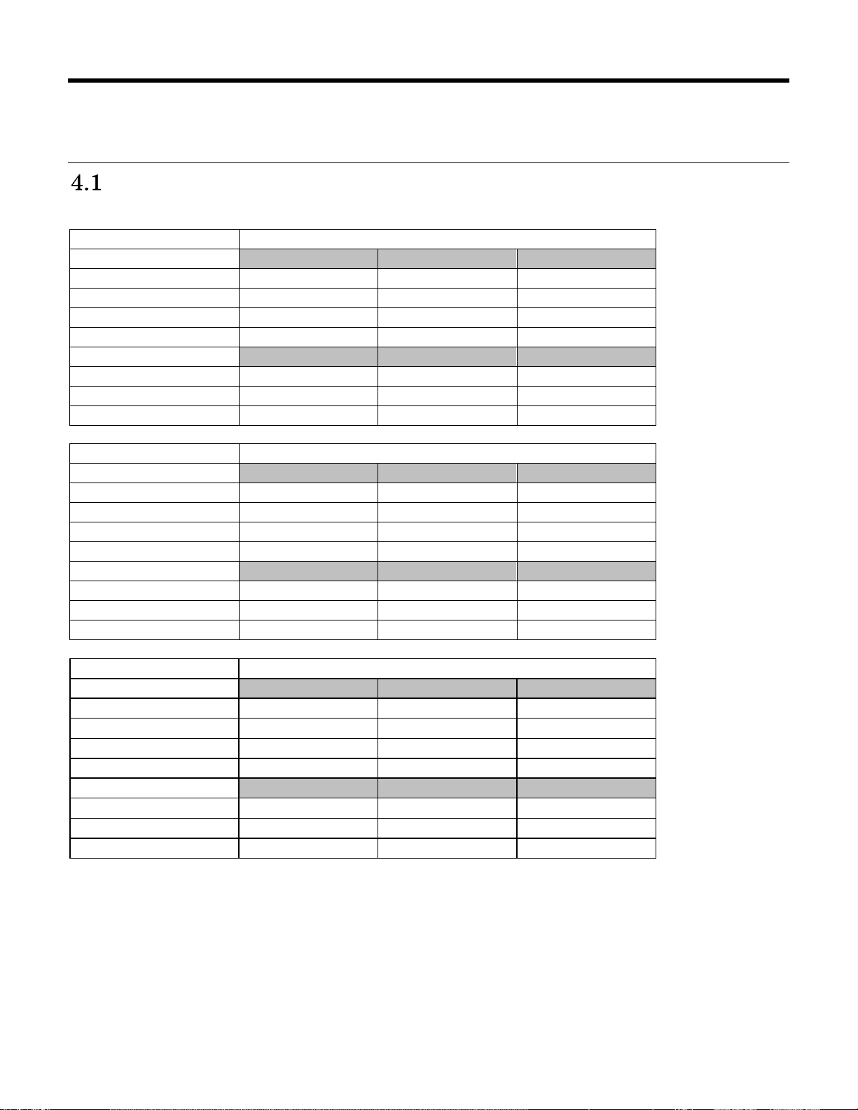
4 Drive characteristics
Description
6TB model
Physical Layout
Label capacity
6TB
6TB
6TB
Bytes per Sector
4,096
4,160
4,224
Number of Heads
10
10
10
Number of disks
5 5 5
Logical Layout
2
Bytes per Sector
512
520
528
Number of Sectors
11,721,045,168
11,521,787,400
11,310,808,584
Total Logical Data Bytes
6,001,175,126,016
5,899,155,148,800
5,791,133,995,008,
Description
5TB model
Physical Layout
Label capacity
5TB
5TB
5TB
Bytes per Sector
4,096
4,160
4,224
Number of Heads
10
10
10
Number of disks
5 5 5
Logical Layout
2
Bytes per Sector
512
520
528
Number of Sectors
9,767,541,168
9,767,541,168
9,425,677,224
Total Logical Data Bytes
5,000,981,078,016
5,000,981,078,016
4,825,946,738,688
Description
4TB model
Physical Layout
Label capacity
4TB
4TB
4TB
Bytes per Sector
4,096
4,160
4,224
Number of Heads
8 8 8
Number of disks
4 or 5
4 or 5
4 or 5
Logical Layout
2
Bytes per Sector
512
520
528
Number of Sectors
7,814,037,168
7,814,037,168
7,540,545,864
Total Logical Data Bytes
4,000,787,030,016
4,000,787,030,016
3,860,759,482,368
This section describes the characteristics of the drive.
Default logical drive parameters
The default of the logical drive parameters in Identify Device data is as shown below.
23
HGST Hard Disk Drive OEM Specification
Page 24
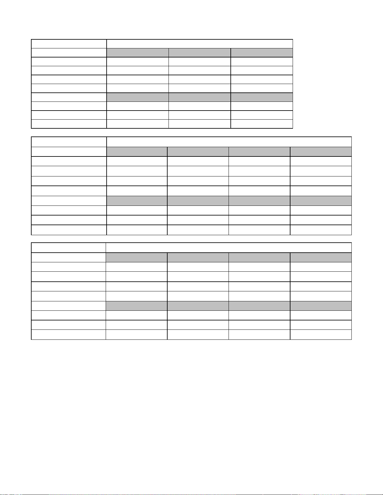
Description
2TB model
Physical Layout
Label capacity
2TB
2TB
2TB
Bytes per Sector
4,160
4,160
4,224
Number of Heads
4 4 4
Number of disks
2 2 2
Logical Layout
2
Bytes per Sector
512
520
528
Number of Sectors
3,907,029,168
3,907,029,168
3,770,283,144
Total Logical Data Bytes
2,000,398,934,016
2,000,398,934,016
1,930,384,969,728
Description
6TB model
Physical Layout
Label capacity
6TB
6TB
6TB
6TB
Bytes per Sector
4,096
4,112
4,160
4,224
Number of Heads
10
10
10
10
Number of disks
5 5 5
5
Logical Layout
2
Bytes per Sector
4,096
4,112
4,160
4,224
Number of Sectors
1,465,130,646
1,459,270,120
1,440,223,425
1,413,851,073
Total Logical Data Bytes
6,001,175,126,016
5,977,170,411,520
5,899,155,148,000
5,791,133,995,008
Description
5TB model
Physical Layout
Label capacity
5TB
5TB
5TB
5TB
Bytes per Sector
4,096
4,112
4,160
4,224
Number of Heads
10
10
10
10
Number of disks
5 5 5
5
Logical Layout
2
Bytes per Sector
4,096
4,112
4,160
4,224
Number of Sectors
1,220,942,646
1,216,058,872
1,220,942,646
1,178,209,653
Total Logical Data Bytes
5,000,981,078,016
4,980,977,139,712
5,000,981,078,016
4,825,946,738,688,
HGST Hard Disk Drive OEM Specification
24
Page 25
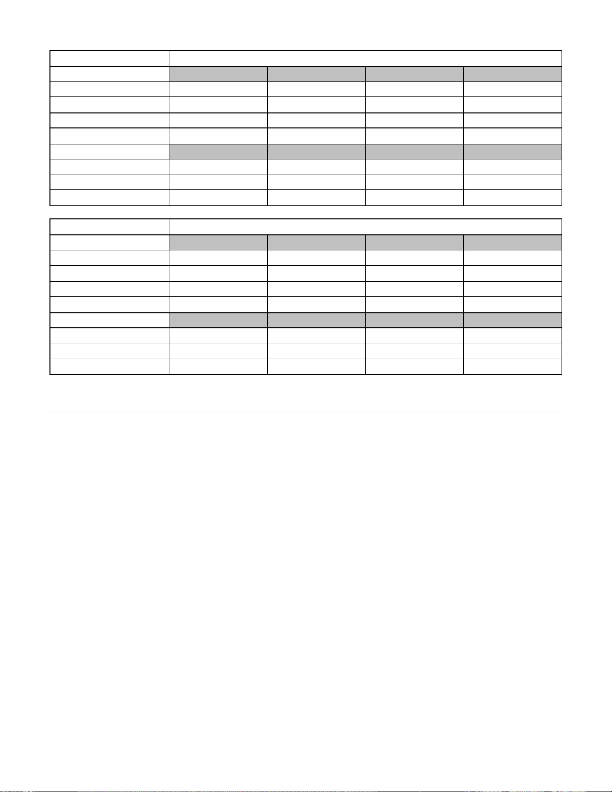
Description
4TB model
Physical Layout
Label capacity
4TB
4TB
4TB
4TB
Bytes per Sector
4,096
4,112
4,160
4,224
Number of Heads
8 8 8
8
Number of disks
4 or 5
4 or 5
4 or 5
4 or 5
Logical Layout
1
Bytes per Sector
4,096
4,112
4,160
4,224
Number of Sectors
976,754,646
972,847,624
976,754,646
942,568,233
Total Logical Data Bytes
4,000787,030,016
3,984,783,867,904
4,000,787,030,016
3,860,759,482,368
Description
2TB model
Physical Layout
Label capacity
2TB
2TB
2TB
2TB
Bytes per Sector
4,096
4,112
4,160
4,224
Number of Heads
4 4 4
4
Number of disks
2 2 2
2
Logical Layout
1
Bytes per Sector
4,096
4,112
4,160
4,224
Number of Sectors
488,378,646
486,425,128
488,378,646
471,285,393
Total Logical Data Bytes
2,000,398,934,016
1,992,397,324,288
2,000,398,934,016
1,930,384,969,728
Table 2 Formatted capacity
Notes:
1
Logical layout: Logical layout is an imaginary drive parameter (that is, the number of heads) which is used to
access the drive from the system interface. The Logical layout to Physical layout (that is, the actual Head and
Sectors) translation is done automatically in the drive. The default setting can be obtained by issuing an IDENTIFY
DEVICE command
HGST Hard Disk Drive OEM Specification
25
Page 26
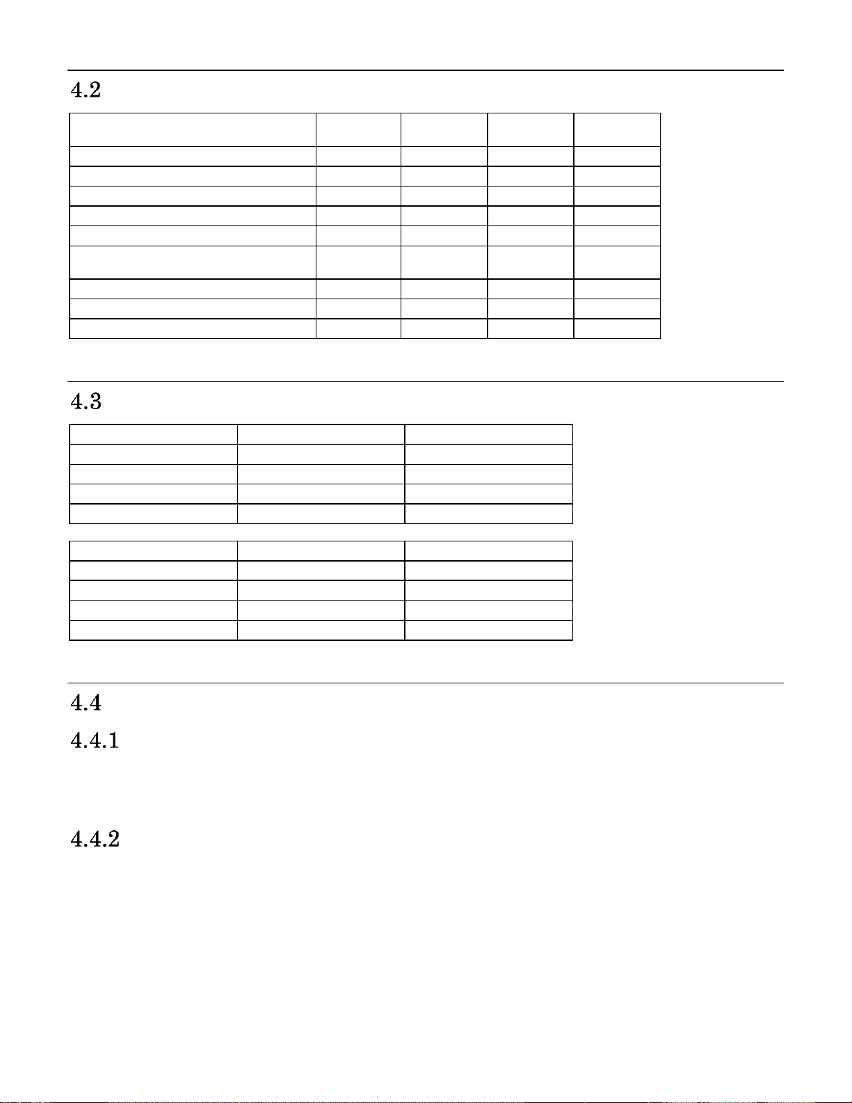
Data sheet
Description
6TB
Model
5TB
Model
4TB
Model
2TB
Model
Max Data transfer rate (Mbps)
2,193
1,825
1,825
1,825
Interface transfer rate (MB/s)
1,200
1,200
1,200
1,200
Typ Sustained transfer rate (MB/s)
226
201
201
201
Data buffer size (MB)
128
128
128
128
Rotational speed (RPM)
7,200
7,200
7,200
7,200
Configurable number of buffer
segment Number
2,048 max
2,048 max
2,048 max
2,048 max
Recording density- max (Kbpi)
1,943
1,621
1,621
1,621
Track density (Ktpi)
355
355
355
355
Areal density - max (Gbits/in2)
690
575
575
575
Description
6TB Model
5TB model
Organization
HGST
HGST
Manufacturing Site
Thailand
Thailand
Product
Ultrastar 7K6000-6000
Ultrastar 7K6000-5000
Block Assignment
Thailand:242h,24Dh
Thailand:242h,24Dh
Description
4TB model
2TB model
Organization
HGST
HGST
Manufacturing Site
Thailand
Thailand
Product
Ultrastar 7K6000-4000
Ultrastar 7K6000-2000
Block Assignment
Thailand:243h/244h
Thailand:245h
Table 3 Mechanical positioning performance
World Wide Name Assignment
Table 4 World Wide Name Assignment
Drive organization
Drive Format
Upon shipment from HGST Japan manufacturing the drive satisfies the sector continuity in the physical format by
means of the defect flagging strategy described in Section 5 on page 29 in order to provide the maximum
performance to users.
Cylinder allocation
Physical cylinder is calculated from the starting data track of 0. It is not relevant to logical CHS. Depending on the
capacity some of the inner zone cylinders are not allocated.
Data cylinder
This cylinder contains the user data which can be sent and retrieved via read/write commands and a spare area for
reassigned data.
Spare cylinder
The spare cylinder is used by HGST Japan manufacturing and includes data sent from a defect location.
26
HGST Hard Disk Drive OEM Specification
Page 27
Performance characteristics
Command Type
Typical (ms)
Max (ms)
Read
7.6
9.0
Write
8.0
10.0
Typical.
The average of the drive population tested at nominal environmental and voltage conditions.
Max.
The maximum value measured on any one drive over the full range of the environmental and
voltage conditions. (See Section 6.2, “Environment” and Section 6.3, “DC Power Requirements”)
Function
Typical (ms)
Max (ms)
Read
0.25
0.35
Write
0.30
0.40
Rotational speed
Time for a revolution
(ms)
Average latency
(ms)
7200 RPM
8.3
4.16
Drive performance is characterized by the following parameters:
Command overhead
Mechanical positioning
- Seek time
- Latency
Data transfer speed
Buffering operation (Look ahead/Write cache)
All the above parameters contribute to drive performance. There are other parameters that contribute to the
performance of the actual system. This specification defines the characteristics of the drive, not the characteristics
of the system throughput which depends on the system and the application.
Mechanical positioning
Average seek time (without command overhead, including settling)
Table 5 Average seek time
The terms “Typical” and “Max” are used throughout this specification with the following meanings:
Single track seek time (without command overhead, including
settling)
Common to all models and all seek modes
Table 6 Single Track Seek Time
Average latency
Table 7 Latency Time
27
HGST Hard Disk Drive OEM Specification
Page 28
Drive ready time
Power on to ready
Typical (sec)
Maximum (sec)
5 Disk model
20
30
Ready
The condition in which the drive is able to perform a media access command (such as read, write) immediately
Power on
This includes the time required for the internal self diagnostics.
Operating mode
Description
Spin-up
Start up time period from spindle stop or power down
Seek
Seek operation mode
Write
Write operation mode
Read
Read operation mode
Unload Idle
Spindle rotation at 7200 RPM with heads unloaded
Idle
Spindle motor is working normally. Servo system is sleeping or waking up. Commands can
be received and processed immediately
Standby
Actuator is unloaded and spindle motor is stopped. Commands can be received
immediately
From
To
RPM
Typical Transition
time(sec)
Max Transition
time(sec)
Standby
Idle
0 -> 7200
15
30
Idle
Standby
7200 -> 0
Immediately
Immediately
Unload idle
Idle
7,200
1
30
Idle
Unload Idle
7,200
Immediately
Immediately
Low RPM
Idle
6300 -> 7200
4
30
Note: The command is processed immediately but there will be an actual spin down time reflecting the seconds
passed until the spindle motor stops.
Table 8 Drive ready time
Operating modes
Operating mode descriptions
Note: Upon power down or spindle stop a head locking mechanism will secure the heads in the OD parking
position.
Mode transition times
Mode transition times are shown below.
Table 9 Mode transition times
28
HGST Hard Disk Drive OEM Specification
Page 29

5 Defect flagging strategy
N N+1 N+2 N+3
defect defect
skip
skip
Media defects are remapped to the next available sector during the Format Process in manufacturing. The mapping
from LBA to the physical locations is calculated by an internally maintained table.
Shipped format
Data areas are optimally used.
All pushes generated by defects are absorbed by the spare tracks of the inner zone.
Figure 1 PList physical format
Defects are skipped without any constraint, such as track or cylinder boundary. The calculation from LBA to
physical is done automatically by internal table.
HGST Hard Disk Drive OEM Specification
29
Page 30
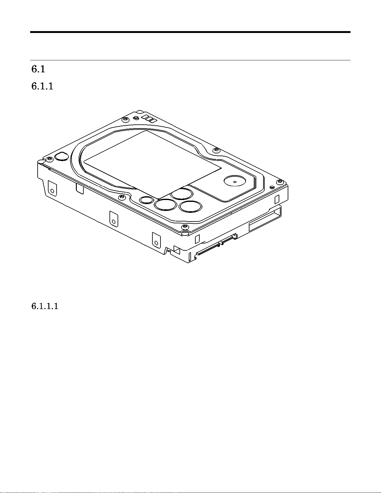
6 Specification
Electrical interface
Connector location
Refer to the following illustration to see the location of the connectors.
* This connector is SATA, shape of SAS connector is shown in Figure 3
Figure 2 Connector location
Signal connector
The drive uses the standard 29 pin Serial Attached SCSI (SAS) connector which conforms to the mechanical
requirements of SFF 8660. The connector is expected to be used in an environment which uses a common
connector structure for racking disk drives in a cabinet. The connector allows for plugging a drive directly into a
backplane by providing the necessary electrical connection. Mechanical stability and device retention must be
provided by a mechanism outside the drive.
30
HGST Hard Disk Drive OEM Specification
Page 31

29 pin Serial Attached SCSI (SAS) Connector Definition
Pin No.
Signal
Description
S1
GND
GND for SAS Primary Port
S2
RP+
SAS Primary Port Receive (positive) signal
S3
RP-
SAS Primary Port Receive (negative) signal
S4
GND
GND for SAS Primary Port
S5
TP-
SAS Primary Port Transmit (negative) signal
S6
TP+
SAS Primary Port Transmit (positive) signal
S7
GND
GND for SAS Primary Port
S8
GND
GND for SAS Secondary Port
S9
RS+
SAS Secondary Port Receive (Positive) signal
S10
RS-
SAS Secondary Port Receive (negative) signal
S11
GND
GND for SAS Secondary Port
S12
TS-
SAS Secondary Port Transmit (negative) signal
S13
TS+
SAS Secondary Port Transmit (Positive) signal
S14
GND
GND for SAS Secondary Port
P1
Vendor Spec
NOT USED (Pins P1-P2 tied internally)
P2
Vendor Spec
NOT USED (Pins P1-P2 tied internally)
P3
POWER DISABLE
POWER DISABLE
P4
GND
GROUND
P5
GND
GROUND
P6
GND
GROUND
P7
+5V-Charge
Pre-charge pin for +5V
P8
+5V
+5V power supply input
P9
+5V
+5V power supply input
P10
GND
GROUND
P11
READY LED
READY LED output
P12
GND
GROUND
P13
+12V=Charge
Pre-charge pin for +12V
P14
+12V
+12V power supply input
P15
+12V
+12V power supply input
Table 10 29-pin Connector Signal Definition
Diagram of top and bottom of connector showing pinouts.
Figure 3 SAS Connector
31
HGST Hard Disk Drive OEM Specification
Page 32

Voltage and Ground Signals
The 12V and 5V contacts provide all of the voltages required by the drive. The two voltages share a common
ground plane to which all of the ground contacts are connected.
Ready LED output
The drive provides an open-drain driver with 15mA of current sink capability to the Ready LED Output signal. The
cathode of the LED should be connected to this signal. The LED and the current-limiting resistor must be provided
by the enclosure
32
HGST Hard Disk Drive OEM Specification
Page 33

Environment
Operating conditions
Temperature
Relative humidity
Maximum wet bulb temperature
Maximum temperature gradient
Altitude
5 to 60°C
8 to 90% non-condensing
29.4°C non-condensing
20°C/Hour
–300 to 3,048 m
Non-Op conditions
Temperature
Relative humidity
Maximum wet bulb temperature
Maximum temperature gradient
Altitude
-40 to 70°C ( storage 0 to 70°C )
5 to 95% non-condensing
35°C non-condensing
30°C/Hour
–300 to 12,000 m (Inside dashed-dotted line of Figure 4)
Temperature and humidity
Table 11 Temperature and humidity
Notes:
1. The system is responsible for providing sufficient ventilation to maintain a surface temperature below 65°C at
the center of the top cover of the drive.
2. Non condensing conditions should be maintained at any time.
3. Maximum storage period within shipping package is one year.
Figure 4 Limits of temperature and altitude
HGST Hard Disk Drive OEM Specification
33
Page 34

Figure 5 Limits of temperature and humidity
Corrosion test
The drive shows no sign of corrosion inside and outside of the hard disk assembly and is functional after being
subjected to seven days at 50°C with 90% relative humidity.
Atmospheric condition
Environments that contain elevated levels of corrosives (e.g. hydrogen sulfide, sulfur oxides, or hydrochloric acid)
should be avoided. Care must be taken to avoid using any compound/material in a way that creates an elevated
level of corrosive materials in the atmosphere surrounding the disk drive. Care must also be taken to avoid use of
any organometallic (e.g. organosilicon or organotin) compound/material in a way that creates elevated vapor levels
of these compounds/materials in the atmosphere surrounding the disk drive.
34
HGST Hard Disk Drive OEM Specification
Page 35

DC power requirements
Input voltage
During run and
spin up
Absolute max
spike voltage
Supply rise time
+5 Volts Supply
5V ± 5%
–0.3 to 5.5V
0 to 5sec
+12 Volts Supply
12V ± 5%
–0.3 to 15.0V
0 to 5sec
The following voltage specification applies at the drive power connector. Connections to the drive should be made
in a safety extra low voltage (SELV) circuit. There is no power on or power off sequencing requirement.
Adequate secondary over-current protection is the responsibility of the system.
Input voltage
Table 12 Input voltage
35
HGST Hard Disk Drive OEM Specification
Page 36

Power supply current (typical
Serial Attached SCSI @12Gb/sec
Current Current Power
IO/Sec +5V Amp +12V Amp Watts
Spin up Peak DC [1] 1.53
Spin up Peak AC 0.60 1.81
Idle_0 Ave. 0.41 0.49 8.0
Idle Ripple [2] 0.16 0.39
Random RW 4KB Qd=4 Peak 0.90 2.13
Random RW 4KB Qd=4 Ave. 132 0.46 0.73 11.0
Random RW 4KB Qd=1 Peak 0.87 2.17
Random RW 4KB Qd=1 Ave. 100 0.45 0.78 11.6
Sequential Read Peak 0.99
Sequential Read Ave. [3] 0.80 0.50 10.0
Sequential Write Peak 0.72
Sequential Write Ave. [3] 0.62 0.53 9.5
BMS Peak 0.9
BMS Ave. 0.7 0.5 9.7
Power Save Mode Current Power
(PHY state: Active) +5V Amp +12V Amp Watts
Watts
Saved
12V DC
peak
12V AC
peak
Idle_A 0.39 0.48 7.7 0.3
Idle_B 0.32 0.40 6.5 1.5
Idle_C 0.32 0.30 5.2 2.8 1.07 1.29
Standby_Y 0.32 0.30 5.2 2.8 1.07 1.29
Standby_Z 0.31 0.004 1.6 6.4 1.49 1.76
Notes
Reference data, sample number = 10HDDs, DE temp. = 40degC (25degC for Spin up), WCE=0
[1] 200mS windowed average
[2] Pk to Pk BWL @20MHz
[3] Max transfer rate
Recovery [1]
1
)
Table 13 SAS power consumption (6TB/5TB/4TB Model)
HGST Hard Disk Drive OEM Specification
36
Page 37

Serial Attached SCSI @12Gb/sec
Current Current Power
IO/Sec +5V Amp +12V Amp Watts
Spin up Peak DC [1] 1.52
Spin up Peak AC 0.60 1.79
Idle_0 Ave. 0.40 0.28 5.3
Idle Ripple [2] 0.17 0.34
Random RW 4KB Qd=4 Peak 0.84 1.85
Random RW 4KB Qd=4 Ave. 137 0.45 0.51 8.4
Random RW 4KB Qd=1 Peak 0.82 1.87
Random RW 4KB Qd=1 Ave. 98 0.44 0.49 8.1
Sequential Read Peak 0.91
Sequential Read Ave. [3] 0.76 0.29 7.2
Sequential Write Peak 0.71
Sequential Write Ave. [3] 0.60 0.33 6.9
BMS Peak 0.9
BMS Ave. 0.7 0.3 6.8
Power Save Mode Current Power
(PHY state: Active) +5V Amp +12V Amp Watts
Watts Saved 12V DC peak 12V AC peak
Idle_A 0.38 0.27 5.1 0.2
Idle_B 0.32 0.23 4.3 1.0
Idle_C 0.32 0.18 3.7 1.6 1.06 1.29
Standby_Y 0.32 0.18 3.7 1.6 1.06 1.29
Standby_Z 0.31 0.004 1.6 3.7 1.49 1.76
Notes
Reference data, sample number = 10HDDs, DE temp. = 40degC (25degC for Spin up), WCE=0
[1] 200mS windowed average
[2] Pk to Pk BWL @20MHz
[3] Max transfer rate
Recovery [1]
Table 14 SAS power consumption (2TB Model)
HGST Hard Disk Drive OEM Specification
37
Page 38

Power supply generated ripple at drive power connector
Maximum (mV pp)
MHz
+5V DC
200
0-10
+12V DC
250
0-10
Power Consumption
Efficiency at Idle
W/TB
1.3 (6TB)
W/GB
0.0013 (6TB)
Table 15 Power supply generated ripple at drive power connector
During drive start up and seeking 12-volt ripple is generated by the drive (referred to as dynamic loading). If the
power of several drives is daisy chained together, the power supply ripple plus the dynamic loading of the other
drives must remain within the above regulation tolerance. A common supply with separate power leads to each
drive is a more desirable method of power distribution.
To prevent external electrical noise from interfering with the performance of the drive, the drive must be held by four
screws in a user system frame which has no electrical level difference at the four screws position and has less than
±300 millivolts peak to peak level difference to the ground of the drive power connector.
Power Consumption Efficiency
Table 16 Power Consumption Efficiency
38
HGST Hard Disk Drive OEM Specification
Page 39

Reliability
Data integrity
No more than one sector is lost at Power loss condition during the write operation when the write cache option is
disabled. If the write cache option is active, the data in write cache will be lost. To prevent the loss of customer
data, it is recommended that the last write access before power off be issued after setting the write cache off.
Cable noise interference
To avoid any degradation of performance throughput or error rate when the interface cable is routed on top or
comes in contact with the HDA assembly, the drive must be grounded electrically to the system frame by four
screws. The common mode noise or voltage level difference between the system frame and power cable ground or
AT interface cable ground should be in the allowable level specified in the power requirement section.
Load/Unload
The product supports a minimum of 600,000 normal load/unloads in a 40° C environment.
Load/unload is invoked by transition of the HDD's power mode.
Idle <-> unload idle
Idle <-> Low rpm idle
Start/stop cycles
The drive withstands a minimum of 50,000 start/stop cycles in a 40° C environment and a minimum of 10,000
start/stop cycles in extreme temperature or humidity within the operating range.
Preventive maintenance
None
Data reliability
Probability of not recovering data is 1 in 1015 bits read.
LDPC on the fly/ offline data correction
600 bit LDPC
This implementation recovers maximum 330 bits single burst error by on the fly correction and maximum
450 bits single burst error by offline correction
Required Power-Off Sequence
The required BIOS sequence for removing power from the drive is as follows:
Step 1: Issue one of the following commands.
STOP UNIT
Note: Do not use the Flash Cache command for the power off sequence because this command does not invoke
Unload
Step 2: Wait until the Command Complete status is returned. In a typical case 350 ms are required for the
command to finish completion; however, the BIOS time out value needs to be 30 seconds considering
error recovery time.
Step 3: Terminate power to HDD
39
HGST Hard Disk Drive OEM Specification
Page 40

Mechanical specifications
Physical dimensions
Figure 6 Top and side views and mechanical dimensions
40
HGST Hard Disk Drive OEM Specification
Page 41

Figure 7 Top and side views and mechanical dimensions (FIPS model)
All dimensions are in millimeters.
41
HGST Hard Disk Drive OEM Specification
Page 42

Figure 8 Bottom and side views with mounting hole locations
All dimensions in the above figure are in millimeters.
42
HGST Hard Disk Drive OEM Specification
Page 43

Figure 9 Bottom and side views with mounting hole locations (FIPS model)
Height (mm)
Width (mm)
Length (mm)
Weight (grams)
26.1 MAX
101.6 ± 0.25
147 MAX
715 Max.
All dimensions in the above figure are in millimeters.
The following table shows the physical dimensions of the drive.
Table 17 Physical Dimensions
43
HGST Hard Disk Drive OEM Specification
Page 44

Connector locations
Figure 10 Connector locations
Drive mounting
The drive will operate in all axes (6 directions). Performance and error rate will stay within specification limits if the
drive is operated in the other orientations from which it was formatted.
For reliable operation, the drive must be mounted in the system securely enough to prevent excessive motion or
vibration of the drive during seek operation or spindle rotation, using appropriate screws or equivalent mounting
hardware.
The recommended mounting screw torque is 0.6 - 1.0 Nm (6-10 Kgf.cm).
The recommended mounting screw depth is 4 mm maximum for bottom and 6.1 mm maximum for horizontal
mounting.
Drive level vibration test and shock test are to be conducted with the drive mounted to the table using the bottom
four screws.
Heads unload and actuator lock
Heads are moved out from disks (unload) to protect the disk data during shipping, moving, or storage. Upon
power down, the heads are automatically unloaded from disk area and the locking mechanism of the head actuator
will secure the heads in unload position.
44
HGST Hard Disk Drive OEM Specification
Page 45

Vibration and shock
Frequency
5 Hz
17 Hz
45 Hz
48 Hz
62 Hz
65 Hz
150 Hz
200 Hz
500 Hz
RMS
(m/sec2)
[(m/sec2)2/Hz]
1.9 x
10E–3
1.1 x
10E–1
1.1 x
10E–1
7.7 x
10E–1
7.7 x
10E–1
9.6 x
10E–2
9.6 x
10E–2
4.8 x
10E–2
4.8
x10E-2
6.57
Frequency
20 Hz
100 Hz
200 Hz
800 Hz
1000 Hz
1500 Hz
1700 Hz
2000 Hz
RMS
(Rad/s2)
[(Rad/s2) 2/Hz]
1.90E02
1.90E02
1.87E01
1.87E01
5.33E02
7.70E03
4.00E03
4.00E03
12.5
All vibration and shock measurements recorded in this section are made with a drive that has no mounting
attachments for the systems. The input power for the measurements is applied to the normal drive mounting points.
Operating vibration
Random vibration (Linear)
The test is 30 minutes of random vibration using the power spectral density (PSD) levels shown below in each of
three mutually perpendicular axes. The disk drive will operate without non-recoverable errors when subjected to the
below random vibration levels.
Table 18 Random vibration PSD profile break points (operating)
The overall RMS (root mean square) level is 6.57 m/sec2 (0.67 G).
Swept sine vibration (Linear)
The drive will meet the criteria shown below while operating in the specified conditions:
No errors occur with 4.9 m/sec2 (0.5 G) 0 to peak, 5 to 300 to 5 Hz sine wave, 0.5 oct/min sweep rate with 3-
minute dwells at two major resonances
No data loss occurs with 9.8 m/sec2 (1 G) 0 to peak, 5 to 300 to 5 Hz sine wave, 0.5 oct/min sweep rate with 3-
minute dwells at two major resonances
Random vibration (Rotational)
The drive will meet the criteria shown below while operating in the specified conditions:
Less than 20% Performance degradation
The overall RMS (Root Mean Square) level of vibration is 12.5Rad/sec^2. PSD profile is shown below.
Table 19 Random vibration (Rotational) PSD profile break points
45
HGST Hard Disk Drive OEM Specification
Page 46
Nonoperating vibration
Frequency
2 Hz
4 Hz
8 Hz
40 Hz
55 Hz
70 Hz
200 Hz
[(m/sec2)2/Hz]
0.096
2.89
2.89
0.289
0.962
0.962
0.096
Acceleration level (m/sec2)
Duration (ms)
2940(300G)
1
1470(150G)
11
The drive does not sustain permanent damage or loss of previously recorded data after being subjected to the
environment described below
Random vibration
The test consists of a random vibration applied for each of three mutually perpendicular axes with the time duration
of 10 minutes per axis. The PSD levels for the test simulate the shipping and relocation environment shown below.
The overall RMS (Root Mean Square) level of vibration is 10.2 m/sec2 (1.04 G).
Table 20 Random vibration PSD profile break points (nonoperating)
Swept sine vibration
19.6 m/sec2 (2 G) (Zero to peak), 5 to 500 to 5 Hz sine wave
0.5 oct/min sweep rate
3 minutes dwell at two major resonances
Operating shock
The drive meets the following criteria while operating in the conditions described below. The shock test consists of
10 shock inputs in each axis and direction for total of 60. There must be a delay between shock pulses long enough
to allow the drive to complete all necessary error recovery procedures.
No error occurs with a 98.1 m/sec2 (10 G) half-sine shock pulse of 11 ms duration
No data loss occurs with a 294 m/sec2 (30 G) half-sine shock pulse of 4 ms duration.
No data loss occurs with a 686 m/sec2 (70 G) half-sine shock pulse of 2 ms duration.
Nonoperating shock
The drive will operate without non-recoverable errors after being subjected to shock pulses with the following
characteristics.
Trapezoidal shock wave
Approximate square (trapezoidal) pulse shape
Approximate rise and fall time of pulse is1 ms
Average acceleration level is 490 m/sec2 (50 G). (Average response curve value during the time following the 1
ms rise time and before the 1 ms fall with a time "duration of 11 ms")
Minimum velocity change is 4.23 m/sec
Sinusoidal shock wave
The shape is approximately half-sine pulse. The figure below shows the maximum acceleration level and duration.
Table 21 Sinusoidal shock wave
46
HGST Hard Disk Drive OEM Specification
Page 47

Nonoperating Rotational shock
Duration
Rad/sec2
1 ms
30,000
2 ms
20,000
All shock inputs shall be applied around the actuator pivot axis.
Table 22 Rotational Shock
47
HGST Hard Disk Drive OEM Specification
Page 48

Acoustics
Mode
7200rpm (Typical / Max)
Idle
2.9 / 3.4
Operating
3.6 / 4.0
Idle mode.
The drive is powered on, disks spinning, track following, unit ready to receive and respond to
interface commands.
Operating mode.
Continuous random cylinder selection and seek operation of the actuator with a dwell time at
each cylinder. The seek rate for the drive is to be calculated as shown below:
The upper limit criteria of the octave sound power levels are given in Bels relative to one picowatt and are shown in
the following table. The sound power emission levels are measured in accordance with ISO 7779.
Table 23 Sound power levels
Mode definition:
Dwell time = 0.5 x 60/RPM
Seek rate = 0.4 / (Average seek time + Dwell time)
Identification labels
The following labels are affixed to every drive shipped from the drive manufacturing location in accordance with the
appropriate hard disk drive assembly drawing:
A label containing the HGST logo, the HGST Japan part number, and the statement “Made by HGST Japan, Ltd.”
or HGST Japan approved equivalent
A label containing the drive model number, the manufacturing date code, the formatted capacity, the place of
manufacture, UL/CSA/TUV/CE/C-Tick mark logos and WEEE/China RoHS logos
A bar code label containing the drive serial number
A label containing the jumper pin description
A user designed label per agreement
The above labels may be integrated with other labels.
48
HGST Hard Disk Drive OEM Specification
Page 49

Safety
UL and CSA standard conformity
The product is qualified per UL60950-1:Second Edition and CAN/CSA-C22.2 No.60950-1-07 Second Edition, for
use in Information Technology Equipment including Electric Business Equipment.
The UL recognition or the CSA certification is maintained for the product life.
The UL and C-UL recognition mark or the CSA monogram for CSA certification appear on the drive.
German Safety Mark
The product is approved by TUV on Test requirement: EN60950-1:2006+A11 but the GS mark is not applicable to
internal devices such as this product.
Flammability
The printed circuit boards used in this product are made of material with the UL recognized flammability rating of V1 or better. The flammability rating is marked or etched on the board. All other parts not considered electrical
components are made of material with the UL recognized flammability rating of V-2 minimum basically.
Safe handling
The product is conditioned for safe handling in regards to sharp edges and corners.
Substance restriction requirements
The product complies with the Directive 2002/95/EC of the European Parliament on the restrictions of the use of the
certain hazardous substances in electrical and electronic equipment (RoHS) and with Halogen free requirements
based on the electronics industry standard, IEC 61249-2-21 (http://www.iec.ch/).
FIPS models do not comply with IEC 61249-2-21.
Secondary circuit protection
Spindle/VCM driver module includes 12 V over current protection circuit.
49
HGST Hard Disk Drive OEM Specification
Page 50

Electromagnetic compatibility
When installed in a suitable enclosure and exercised with a random accessing routine at maximum data rate, the
drive meets the following worldwide EMC requirements:
United States Federal Communications Commission (FCC) Rules and Regulations (Class B), Part 15. (A 6 dB
buffer shall be maintained on the emission requirements).
European Economic Community (EEC) directive number 76/889 related to the control of radio frequency
interference and the Verband Deutscher Elektrotechniker (VDE) requirements of Germany (GOP).Spectrum
Management Agency (SMA) EMC requirements of Australia. The SMA has approved C-Tick Marking for HGST
Japan.
CE Mark
The product is declared to be in conformity with requirements of the following EC directives under the sole
responsibility of HGST Japan, Ltd:
Council Directive 2004/108/EC on the approximation of laws of the Member States relating to electromagnetic
compatibility.
C-Tick Mark
The product complies with the following Australian EMC standard:
Limits and methods of measurement of radio disturbance characteristics of information technology, AS/NZS 3548 :
1995 Class B.
BSMI Mark
The product complies with the Taiwan EMC standard “Limits and methods of measurement of radio disturbance
characteristics of information technology equipment, CNS 13438 Class B.”
KC Mark
The product complies with the Korea EMC standard. The regulation for certification of information and
communication equipment is based on “Telecommunications Basic Act” and “Radio Waves Act” Korea EMC
requirement are based technically on CISPR22 measurement standards and limits. KC standards are likewise
based on IEC standards.
50
HGST Hard Disk Drive OEM Specification
Page 51

Part 2. Interface specification
51
HGST Hard Disk Drive OEM Specification
Page 52

7 SAS Attachment
This section defines some basic terminology and describes the behavior of the drive when attached to a Serial
Attached SCSI (i.e. SAS) domain.
General
This section introduces some of the terminology that is used in describing Serial Attached SCSI (i.e. SAS).
SAS is logically a bi-directional, point to point serial data channel that leverages the SCSI protocol set. Nodes are
physically connected via a port.
Ports may be connected point-to-point via SAS expanders, to form a complex switching network, referred to as a
SAS domain.
SAS is defined in terms of a hierarchy of functions or 'protocol layers'. This discussion will focus in on the aspects of
SAS that are relevant to this product.
SCSI Application Layer - Clause 10
SSP Transport Layer (Serial SCSI Protocol) - Clause 9
SAS Port Layer - Clause 8
SSP Link Layer - Clause 7
SAS PHY Layer - Clause 6
SAS Physical Layer - Clause 5
All layers are defined in the following ANSI standard.
"SAS Protocol Layer - 2 (SPL-3)"
In addition, this drive claims compliance with the following ANSI standards.
SCSI Architecture Model (SAM-5)
SCSI Block Commands (SBC-3)
SAS Features
The following SAS features are supported by the drive.
SAS Compliance
- "Serial Attached SCSI - 3 (SAS-3)"
SAS Protocol
- This drive supports Serial SCSI Protocol (SSP).
- STP (Tunneled SATA) and SMPs (Management protocols) are NOT supported.
52
HGST Hard Disk Drive OEM Specification
Page 53

SAS Dual Ported Operation
- Single PHY ports (i.e. Narrow port. Wide Port NOT supported)
- Ports function independently with separate firmware controls
- Multiple DMA engines capable of accessing either port
- Maximum outstanding credit of four per port
Physical Link Rates
- G1 (1.5 Gbps), G2 (3.0 Gbps), G3 (6.0 Gbps), and G4 (12.0 Gbps) supported
- Largely automated OOB and speed negotiation sequences
- Optional support for the hot-plug timeout in hardware
Partial support for Disconnect/Reconnect Mode Page (0x02)
- Maximum Connect Time Limit - SUPPORTED
- Bus Inactivity Time Limit - NOT SUPPORTED
- Maximum Burst Size - SUPPORTED
- First Burst Size - NOT SUPPORTED
Others...
- Connection Rate Matching
- Hard Reset primitive sequence detection and validation in hardware
- Support for NOTIFY (Power Loss Expected)
- Hashed WWN validation in hardware
- Extended CDB support
53
HGST Hard Disk Drive OEM Specification
Page 54

SAS Names and Identifiers
Object
SAS Implementation
Port Identifier
SAS address
Port Name
Not defined
Device Name
SAS address
PHY Identifier
PHY identifier
Byte/Bit
7 6 5 4 3 2 1 0 0
NAA (5h)
(MSB)
1
IEEE Company ID
2
3
(LSB)
(MSB)
4
Vendor Specific Identifier
(LSB)
5
6
7
Bit
63-60
59-36
35-24
23-2
1-0
0101
OUI in Canonical Form
Block Assignment
S/N
Object
In SAS, device and port names are worldwide unique names within a transport protocol. Port identifiers are the
values by which ports are identified within a domain, and are used as SAS addresses. PHY identifiers are unique
within a device.
Table 24 Names and Identifiers
Where the SAS address format is defined by ANSI as follows:
Table 25 SAS Address Format
The SAS device name is a unique SAS address worldwide name. This device name is reported through the SCSI
Vital Products Data.
Each of the two SAS ports also has a unique SAS address worldwide name. These port identifiers are reported in
the IDENTIFY address frame and are used as source and destination addresses in the OPEN address frame. They
are also reported through the SCSI Vital Products Data.
Since this drive is one device with two ports it has three SAS addresses. All SAS addresses are in 64-bit IEEE
Registered Name format, as illustrated in Table 26.
Table 26 IEEE Registered Name Format
HGST Hard Disk Drive OEM Specification
54
Page 55

The Name Address Authority field (5h) specifies the format used for the rest of the name as follows:
Field
Description
OUI
Organizationally Unique Identifier (24 bits). Canonical form means that
each byte is stored in “bit reversed” order.
Block Assignment
Block assignment within HGST, a Western Digital Company
Object
Device Name/Port Identifier
00b Device
01b Port 1
10b Port 2
11b Not assigned
S/N
Sequentially increasing drive serial number assigned at manufacturing.
Table 27 Name Address Authority field
55
HGST Hard Disk Drive OEM Specification
Page 56

Layer
SAS
Time
Link Reset sequence
Phy Reset sequence
OOB sequence
Speed Negotiation
sequence
Identification sequence
Time
SAS w/Hard Reset
Link Reset sequence with hard error
Phy Reset sequence
Hard Reset sequence
Phy Reset sequence
Identification sequence
The PHY layer defines 8b10b encoding and OOB signals. The PHY layer is the interface between the link layer and
the physical layer. This section describes PHY layer behaviors of the drive. For a complete description of SAS PHY
Layer, please see the ANSI specification, SPL-3.
Link Reset Sequence
The Link Reset sequences for SAS are defined in the SPL-3 ANSI specification with a general overview shown
below. As shown in the diagram, a PHY Reset sequence, consists of an OOB sequence, followed by speed
negotiation. Link Reset sequences will always include a PHY Reset sequence, followed by an Identification
sequence. Inclusion of a Hard Reset sequence is optional. If Hard Reset is performed, it will be preceded by a PHY
Reset sequence, and followed by PHY Reset and an Identification sequence.
Figure 11 Link Reset Sequence
Hard Reset
A Hard Reset sequence on a port will not affect the other port, but the outstanding commands on the other port will
be aborted due to the LUN reset associated with the Hard Reset. The effect of a Hard Reset will be similar to a
Power on Reset, and will result in the re-initialization of all drive resources. The first command issued from every
initiator on the port that received the Hard Reset will result in a CHECK CONDITION with a sense key of UNIT
ATTENTION and an additional sense code of SCSI BUS RESET OCCURRED. The first command issued from
every initiator on the other port will result in a CHECK CONDITION and an additional sense code of BUS DEVICE
RESET OCCURRED.
A Hard Reset sequence will never be issued by the drive. A link reset will be initiated by the drive on the affected
port upon completion of Hard Reset processing.
56
HGST Hard Disk Drive OEM Specification
Page 57

SAS OOB (Out of Band)
Byte /Bit 7 6 5 4 3 2 1 0
0
Start =1b
TX SSC
Type = 0b
Reserved
Requested Logical Link Rate = 0h
1
G1 Without
SSC=1b
G1 With
SSC=1b
G2 Without
SSC=1b
G2 With
SSC=1b
G3 Without
SSC=1b
G3 With
SSC=1b
G4
Without
SSC=1b
G4 With
SSC=1b
2
Reserved
3
Reserved
Parity
Out of Band (OOB) signals are low-speed signal patterns detected by the PHY that do not appear in normal data
streams. They consist of defined amounts of idle time followed by defined amounts of burst time. During the idle
time, D.C. idle is transmitted. During the burst time, ALIGN (0) primitives are transmitted repeatedly. The signals are
differentiated by the length of idle time between the burst times.
As a SAS compliant device, the drive uses three OOB signals: COMINIT/COMRESET and COMWAKE and
COMSAS.OOB operations are beyond the scope of this specification. Please refer to the ANSI SPL-3 specification
for more details.
The drive will initiate OOB by sending COMINITs, under the following conditions:
- POR
- Loss of sync
- Identify timeout
SAS Speed Negotiation
The drive supports G1 (1.5 Gbps), G2 (3.0 Gbps), G3 (6.0 Gbps), and G4 (12.0 Gbps) negotiation speeds. The
default maximum negotiation rate is G4 speed (per byte 32 in the PHY Control and Discover Mode Page 19
subpage 1). Drive is SAS3 device and supports SNW-1, SNW-2, SNW-3 speed negotiation with PHY capabilities
exchange, and both transmitter training (Train_Tx-SNW, at 12G only) and receiver training (Train_Rx-SNW or
Train-SNW). The drive’s PHY capabilities are defined in table below:
PHY Capabilities:
Table 28 SAS Speed Negotiation
Start is set to 1 to indicate the beginning of the PHY capabilities
TX SSC Type is set to 1 to indicate that PHY’s transmitter uses center-spreading-SSC when SSC is enabled
TX SSC Type is set to 0 to indicate that PHY’s transmitter uses down-spreading-SSC when SSC is enabled
Requested Logical Link Rate field is set to 0 to indicate that drive does not support multiplexing
G1 Without SSC is set to 1 to indicate that drive supports G1 (1.5 Gbps) without SSC
G2 Without SSC is set to 1 to indicate that drive supports G2 (3.0 Gbps) without SSC
G3 Without SSC is set to 1 to indicate that drive supports G3 (6.0 Gbps) without SSC
G4 Without SSC is set to 1 to indicate that drive supports G4 (12.0 Gbps) without SSC
G1 With SSC set to 1 to indicate that drive supports G1 (1.5 Gbps) with SSC
G2 With SSC set to 1 to indicate that drive supports G2 (3.0 Gbps) with SSC
G3 With SSC set to 1 to indicate that drive supports G3 (6.0 Gbps) with SSC
G4 With SSC is set to 1 to indicate that drive supports G4 (12.0 Gbps) with SSC
Parity is set to 1 for even parity of the total number of SNW-3 PHY capabilities, including Start bit.
Training is based on the highest untried commonly supported settings on the exchanged SNW-3 supported settings
bits. If a Train-SNW is invalid and there are additional, untried, commonly supported settings exchanged during
SNW-3, then a new Train-SNW will be performed based on the next highest untried, commonly supported settings.
57
HGST Hard Disk Drive OEM Specification
Page 58

Table 29 defines the priority of the supported settings bits.
Priority
Bit
Highest
G4 With SSC bit
...
G4 Without SSC bit
...
G3 With SSC bit
...
G3 Without SSC bit
...
G2 With SSC bit
…
G2 Without SSC bit
…
G1 With SSC bit
G1 Without SSC bit
Lowest
Error
Error Handling Procedure
Link Reset
After POR or Hard Reset, the drive initiates link reset by transmitting exactly 1 COMINIT.
For other resets, the drive does not initiate Link Reset.
COMINIT Timeout
If COMINIT or COMSAS is not received before the ”Hot Plug Timeout" period expires, the
drive continues to transmit DC zero and wait for COMINIT/COMSAS. Firmware is notified.
This is not considered an error.
COMSAS Timeout
If COMINIT is detected, COMSAS is transmitted, and COMSAS is not received before the
COMSAS Detect Timeout timer expires, firmware is notified and the drive continues to
transmit DC zero and wait for COMINIT.
Speed Negotiation
Errors
If speed negotiation fails with no match, or if the drive fails retrying the matched link rate,
firmware is notified and the drive continues to transmit DC zero and wait for COMINIT. If the
match link rate retry fails, the PHY Reset Problem counter is incremented (Log Page 0x18).
Loss of Sync
If the drive loses Dword sync long enough for the loss of sync timer to expire, firmware is
notified and the drive transmits a COMINIT to initiate a new link reset. The loss of Dword
sync counter is incremented (Log Page 0x18).
Disparity/Invalid
Dword Error
If a disparity error or an invalid Dword is detected by the drive, the Invalid Dword Count is
incremented (Log Page 0x18). The Running Disparity Error Count in Log Page 0x18 is not
used
Table 29 Supported Settings Bit Priorities
PHY Error Handling
This section defines the PHY layer error handling of the drive.
Table 30 PHY Layer Error Handling
HGST Hard Disk Drive OEM Specification
58
Page 59

Link Layer
Byte
Bit
7 6 5 4 3 2 1
0
0
RSVD
Device Type
Address Frame Type
1-27
Frame Type Dependent bytes
28-31
CRC
Value
Address Frame Type Description
0000b
IDENTIFY: Identification Sequence
0001b
OPEN: Connection Request
Others
Reserved
Byte
Bit
7 6 5 4 3 2 1
0
0
RSVD
Device Type = 1h
Address Frame Type = 0
1
Reserved
Reason
2
Reserved
SSP
Initiator Port
STP
Initiator Port
SMP
Initiator Port
RSVD
3
Reserved
SSP
Target Port
STP
Target Port
SMP
Target Port
RSVD
4-11
Device Name
12-19
SAS Address
20
PHY Identifier
21
Persistent
Capable
Power Capable
Slumber
Capable
Partial
Capable
Inside
ZPSDS
Persistent
Requested
Inside
ZPSDS
Break_Reply
Capable=1b
22
Pwr_DIS
Capable
23-27
Reserved
28-31
CRC
The SAS Link layer defines primitives, address frames, and connections. The Link layer is the interface between the
Port layer and the PHY layer. This section describes Link layer behaviors of the drive. For a complete description of
SAS Link layer, please see the ANSI specification, SPL-3.
Address Frames
Address frames are used for the identification sequence and for connection requests and are only sent outside
connections. The Address Frame format is defined below:
Table 31 Address Frame Format
Address Frame Type indicates the type of address frame and is defined in Table 32. This field determines the
definition of the frame type dependent bytes.
Table 32 Frame Type:
Identify Address Frame
The Identify Address Frame format is used for the identification sequence. The Identify Address Frame is sent after
the PHY reset sequence completes. The Identify Address Frame format is defined as follows:
Table 33 Identify Address Frame
59
HGST Hard Disk Drive OEM Specification
Page 60

Device Type is set to 001b to indicate that this drive is an "End Device"
Value
Address Frame Type Description
00b
Power on
01b
OPEN: Connection Request
02b
Hard Reset
(received a Hard Reset during hard reset sequence)
04b
Loss of Dword synchronization
07b
Break timeout timer expired
08b
PHY test function stopped
Others
RESERVED
Address Frame Type is set to 00b to indicate that this is an IDENTIFY
Reason indicates the reason for link reset sequence as defined in Table 34
Initiator Port bits is set to 000b since this device is a target device only
Target Port bits is set to 100b since this device is a SSP target device only
Device Name contains Target Device Identifier
SAS Address contains the port identifier of the SAS port transmitting this frame
PHY Identifier contains the PHY identifier of the PHY transmitting this frame
Persistent Capable is set to 0b to indicate the drive does not support persistent connections
Power Capable is set to 00b to indicate drive does not issue PWR_REQ or PWR_DONE, and does not
respond to PWR_GRANT
Slumber Capable is set to 0b to indicate drive does not support slumber power PHY mode
Partial Capable is set to 0b to indicate drive does not support partial power PHY mode
Inside ZPSDS Persistent: set to 0b since this is an "End Device"
Requested Inside ZPSDS: set to 0b since this is an "End Device"
Break_Reply Capable: set to 1b to indicate that this port is capable of sending BREAK_REPLY primitive
sequence in responding of receiving BREAK primitive sequences
Pwr_DIS Capable is set to 1b to indicate the drive does support the PWR_DIS signal as defined in SAS-3
Table 34 Reason Field
HGST Hard Disk Drive OEM Specification
60
Page 61

Open Address Frame
Byte
Bit
7
6 5 4 3 2 1 0
0
Initiator Port=0
Protocol = 1
Address Frame Type = 1
1
Features = 0
Connection Rate = 8h, 9h, Ah, or Bh
2-3
Initiator Connection Tag
4-11
Destination SAS Address
12-19
Source SAS Address
20
Source Zone Group
21
Pathway Blocked Count
22-23
Arbitration Wait Time
24-27
More Compatible Features
28-31
CRC
The Open Address Frame format is used for the identification sequence. The Open Address Frame is sent after the
PHY reset sequence completes. The Open Address Frame format is defined as follows:
Table 35 Open Address Frame Format
Initiator Port is set to zero when the drive is the source port acting as a SAS target
Protocol is set to 001b to indicate SSP Protocol
Features is set to zero and ignored by the drive per SPL-3
Connection Rate is set to 8h (1.5Gbps), 9h (3Gbps), Ah (6Gbps), or Bh (12Gbps), depending on requested link
rate. Rate matching is supported by the drive, therefore if the link to the drive is 3.0Gbps, and the Connection
Rate is 1.5Gbps, the drive will insert ALIGNs between Dwords, to match the Connection Rate.
Initiator Connection Tag is set by the drive to the last value received from this Initiator.
Destination SAS Address contains the port identifier of the SAS port to which a connection is being requested.
Source SAS Address contains the port identifier on the port that originated this frame (i.e. the drive’s port
address).
Source Zone Group is set to zero and ignored by the drive per SPL-3
Pathway Blocked Count indicates the number of times the port has retried this connection request due to
receiving OPEN_REJECT (PATHWAY BLOCKED). The drive will not increment the PATHWAY BLOCKED
COUNT value past FFh.
Arbitration Wait Time indicates how long the port transmitting the OPEN address frame has been waiting for a
connection request to be accepted. For values from 0000h to 7FFFh, the Arbitration Wait Time timer increments
in one microsecond steps. For values from 8000h to FFFFh, the Arbitration Wait Time timer increments in one
millisecond step.
More Compatible Features is set to zero and ignored by the drive per SPL-3.
61
HGST Hard Disk Drive OEM Specification
Page 62

Link Layer Error Handling
Error
Error Handling Procedure
IDENTIFY Timeout
If IDENTIFY is not received before the IDENTIFY timer expires (1ms), firmware is
notified and the drive transmits a COMINIT to initiate a new link reset.
BREAK Received
If BREAK is received while the drive has ACK/NAK balance, BREAK or BREAK_REPLY
is transmitted and a new connection may be opened if the drive still has frames to
transmit. Firmware is not notified. If BREAK is received while the drive does NOT
have ACK/NAK balance, BREAK or BREAK_REPLY is transmitted and the current
command is aborted and will return Check Condition status with sense data indicating
an ACK/NAK timeout.
NAK and ACK/NAK
Timeout
If a NAK is received on a RESPONSE frame, the RESPONSE frame is retransmitted
with the RETRANSMIT bit set to one. If an ACK or NAK is not received for a
RESPONSE frame within 1ms, the RESPONSE frame will be retransmitted with the
RETRANSMIT bit set to one. The drive will retry sending a RESPONSE frame once.
Bad Frame CRC
If a frame fails the CRC check, the frame is NAKed by the drive and discarded. This is a
link layer function. The command associated with a NAKed DATA or XFER_RDY frame
is aborted with check condition status and sense data corresponding to
DATA_PHASE_ERROR is returned. COMMAND frames that fail the CRC check are
NAKed and discarded.
This section defines the Link layer error handling of the drive.
Table 36 Link Layer Error Handling (part 1 of 2)
HGST Hard Disk Drive OEM Specification
62
Page 63

Error
Error Handling Procedure
OPEN_REJECT
OPEN_REJECT – Retry-able Variations
OPEN_REJECT (RETRY) - Will be retried indefinitely by the drive. This
case is considered to occur when the initiator is temporarily not available to
accept connections
OPEN_REJECT (RATE_NOT_SUPPORTED) – If this occurs, it must mean
that a link between the drive and initiator negotiated to a lower link rate
after the command was received. The drive will retry at the connection at a
lower rate, and if a connection eventually fails for this session at 1.5Gbps,
the command is internally aborted.
OPEN_REJECT – (PATHWAY_BLOCKED) – handled the same as
OPEN_REJECT(RETRY)
OPEN_REJECT(BAD_DESTINATION) – handled the same as
OPEN_REJECT(RETRY)
OPEN_REJECT – Non-Retry-able Variations – If these are received, the
command is internally aborted by the drive
OPEN_REJECT(BAD_DESTINATION)
OPEN_REJECT(WRONG_DESTINATION)
OPEN_REJECT(PROTOCOL_NOT_SUPPORTED)
Credit Timeout
If credit is not received before the credit timer expires, DONE
(CREDIT_TIMEOUT) is sent to the Initiator.
DONE Timeout
If credit is extended and the DONE timer expires, BREAK is sent by hardware to
tear down the connection.
CREDIT_BLOCKED
If CREDIT BLOCKED is received and the drive has frames to send in the current
connection, DONE (CREDIT_TIMEOUT) is returned. Otherwise, DONE
(NORMAL) is returned.
OPEN Frame Checking
Reserved fields in the OPEN frame are not checked.
The Dest Address field is checked, and if it doesn’t match
OPEN_REJECT(WRONG_DESTINATION) is returned.
The Protocol field is checked and if it isn’t set to SSP
OPEN_REJECT(PROTOCOL_NOT_SUPPORTED) is returned.
If the Link Rate exceeds the physical link rate on that port,
OPEN_REJECT(LINK_RATE_NOT_SUPPORTED) is returned.
The Initiator bit is not checked.
OPEN Response Timeout
If AIP or OPEN_ACCEPT is not received before the OPEN Response timer
expires, the hardware transmits BREAK.
CLOSE Timeout
If CLOSE is not received before the CLOSE timer expires, the hardware transmits
BREAK.
PHY Not Ready
If Link Reset occurs outside of a connection, commands can execute normally
across the link reset. If a link reset occurs inside of a connection, the behavior is
similar to BREAK in that it is treated as an abruptly closed connection. In cases
where the command cannot be continued normally (e.g. a frame is corrupted by
OOB signals, or we do not have ACK/NAK balance), the command is terminated
with CHECK CONDITION status with sense data corresponding to ACK/NAK
TIMEOUT.
Table 37 Link Layer Error Handling (part 2 of 2)
HGST Hard Disk Drive OEM Specification
63
Page 64

Transport Layer
Byte
Bit
7 6 5 4 3 2 1
0
0
Frame Type
1-3
Hashed Destination Address
4
Reserved
5-7
Hashed Source Address
10
Reserved
TLR Control = 00b
Retry Data
Frames =0b
Retransmit
RSVD
11
Reserved
# of fill bytes
12-15
Reserved
16-17
Tag
18-19
Target Port Transfer Tag
20-23
Data Offset
24-m
Information Unit
Fill Bytes (if needed)
(n-3)-
n
CRC
Code
Name of Frame
Information
Unit
Originator
IU Size (bytes)
01h
DATA
Data
Initiator or Target
1-1024
05h
XFER_RDY
Data Transfer
Ready
Target
12
06h
COMMAND
Command
Initiator
28-284
07h
RESPONSE
Response
Target
24-1024
16h
TASK
Task
Management
Function
Initiator
28
f0-ffh
Vendor Specific
all
others
Reserved
The Transport layer defines frame formats. The Transport layer is the interface between the Application layer and
Port layer. It is responsible for constructing and parsing frame contents. For SSP, the Transport layer only receives
frames from the Port layer that are going to be ACKed by the Link layer. This section describes Transport layer
behaviors of the drive. For a complete description of SAS Transport layer, please see the ANSI specification, SPL-
3.
The Transport layer defines the frame format as follows.
Table 38 SAS Frame Format
FRAME TYPE field, which defines the format of the INFORMATION UNIT field as follows:
Table 39 FRAME TYPE Field
Hashed Destination SAS Address contains the hashed value of the destination SAS address
Hashed Source SAS Address contains the hashed value of the source SAS address
HGST Hard Disk Drive OEM Specification
64
Page 65

TLR Control is not supported
Byte
Bit
7
6 5 4 3 2 1 0
0-7
Logical Unit Number
8
Reserved
9
Disable First
Burst=0
Reserved
Task
Attribute
10
Reserved
11
Additional CDB Length (in Dwords)
Reserved
12-27
CDB
28-n
Additional CDB Bytes
Value
Attribute
000b
Simple_Q
001b
Head_of_Q
010b
Ordered_Q
100b
ACA_Q (not supported)
101b
Reserved
Retry Data Frames is not supported
Changing Data Pointer is not supported
Number of Fill Bytes indicates the number of fill bytes between the INFORMATION UNIT field and the CRC
field. The Retransmit bit is set to one for RESPONSE frames when attempting to retransmit this frame due to
receiving an error during the initial transmission. It shall be set to zero for all other frame types. The Number of
Fill Bytes field shall be set to zero for all frame types except DATA frames
Tag field contains a value that allows the SSP port to establish a context for commands and task management
functions
Target Port Transfer Tag is set and used by the drive. The initiator should echo this field in outbound data IU.
Information Unit contains the information unit, the format of which is defined by the FRAME TYPE field.
Fill bytes shall be included after the INFORMATION UNIT field so the CRC field is aligned on a four byte
boundary.
Command Information Unit
The COMMAND frame is sent by an SSP initiator port to request that a command be processed by the drive.
Table 40 COMMAND Information Unit
Logical Unit Number contains the address of the logical unit. The drive only supports a LUN of 0’s.
Disable First Burst is not supported by the drive
Task Attribute is defined as follows:
Table 41 Task Attribute Field
Additional CDB Length contains the length in Dwords (four bytes) of the ADDITIONAL CDB field.
CDB and Additional CDB Bytes together contain the CDB.
HGST Hard Disk Drive OEM Specification
65
Page 66

TASK Information Units
Byte
Bit
7 6 5 4 3 2 1
0
0-7
Logical Unit Number
8-9
Reserved
10
Task Management Function
11
Reserved
12-13
Tag of Task to be Managed
14-27
Reserved
Value
Function
01h
ABORT TASK: The drive shall perform the ABORT TASK associated with the value of the TAG OF
TASK TO BE MANAGED field
02h
ABORT TASK SET: The drive shall perform the ABORT TASK SET by aborting all outstanding tasks
for the Initiator that sent the TMF.
04h
CLEAR TASK SET: This TMF causes the drive to abort all tasks in the task set. The action is
equivalent to receiving a series of Abort Task requests from all Initiators.
A unit attention condition shall be generated for all other Initiators with tasks in the task set. The
Additional Sense Code shall be Commands cleared by another Initiator.
08h
LUN RESET: The LUN RESET causes the Target to execute a hard reset. This means:
1. Abort all tasks for all Initiators on either both ports.
2. Release any device reservation on either port.
3. Set a Unit Attention condition for all Initiators.
10h
I_T NEXUS RESET: The I_T NEXUS RESET causes the drive to abort all outstanding tasks for the
Initiator that sent the TMF. In addition, a Unit Attention is set for the initiator that sent the TMF,
indicating I_T NEXUS LOSS. This TMF does not affect task sets for other initiators.
40h
CLEAR ACA (not supported)
80h
QUERY TASK: The drive shall return a response of FUNCTION SUCCEEDED if the specified task
exists, or FUNCTION COMPLETE if the specified task does not exist.
81h
QUERY TASK SET: The drive shall return a response of FUNCTION SUCCEEDED if there is any
task exist, or FUNCTION COMPLETE if there is no task exist.
82h
QUERY ASYNCHRONOUS EVENT (formerly QUERY UNIT ATTENTION): The drive shall return a
response of FUNCTION SUCCEEDED if there is a unit attention or a deferred error pending, or
FUNCTION COMPLETE if there is no unit attention or no deferred error pending.
others
RESERVED: The Drive will return a RESPONSE frame with the DATAPRES field set to
RESPONSE_DATA and its RESPONSE CODE field set to TASK MANAGEMENT FUNCTION NOT
SUPPORTED.
Table 42 TASK Information Unit
Logical Unit Number field contains the address of the logical unit. The drive only supports a LUN of 0’s.
Task Management Function field is defined as follows:
Table 43 TASK MANAGEMENT FUNCTION Field
If TMF is set to ABORT TASK or QUERY TASK, the Tag of Task to be Managed field specifies the TAG value
from the COMMAND frame that contained the task to be aborted or checked. For all other TMF’s, this field is
ignored.
If TMF is set to QUERY ASYNCHRONOUS EVENT, the Additional Response Information argument is set to
000000h for the response of FUNCTION COMPLETE. If the response is FUNCTION SUCCEED, the Additional
Response Information argument is set as defined in Table 44.
HGST Hard Disk Drive OEM Specification
66
Page 67

Byte
Bit
7 6 5 4 3 2 1
0
0
Reserved
UADE Depth
Sense Key
1
Additional Sense Code
2
Additional Sense Code Qualifier
Table 44 Additional Response Information Argument for Query Async Event
Code
Description
00b
The combined number of unit attention conditions and deferred errors is unknown
01b
The combined number of unit attention conditions and deferred errors is one
10b
The combined number of unit attention conditions and deferred errors is greater than one
11b
Reserved
Byte
Bit
7 6 5 4 3 2 1
0
0 - 3
Requested Offset
4 - 7
Write Data Length
8 - 11
Reserved
Byte
Bit
7 6 5 4 3 2 1 0 0 - (n-1)
Data
UADE Depth is the number of pending unit attention conditions or deferred errors. It is defined as in Table 45
Sense Key is the value of the SENSE KEY field in the highest-priority pending unit attention condition or
deferred error.
Additional Sense Code is the value of the ADDITIONAL SENSE CODE field in the highest-priority pending unit
attention condition or deferred error.
Additional Sense Code Qualifier is the value of the ADDITIONAL SENSE CODE QUALIFIER field in the
highest-priority pending unit attention condition or deferred error
Table 45 UADE DEPTH Field
XFER_RDY Information Units
The XFER_RDY frame is sent by the drive to request write data (i.e. out bound data) from the initiator.
Table 46 XFER_RDY Information Units
Requested Offset contains the buffer offset of the segment of write data the Initiator may transmit to the drive
(using DATA frames). The requested offset shall be a multiple of four.
Write Data Length contains the number of bytes of write data the Initiator may transmit to the drive (using
DATA frames) from the requested offset.
DATA Information Units
The DATA frame is sent by the drive to the Initiator (in bound data) or by the Initiator to the drive (out bound data).
Table 47 Data Information Unit
67
HGST Hard Disk Drive OEM Specification
Page 68

RESPONSE Information Units
Byte
Bit
7 6 5 4 3 2 1
0
0-7
Reserved
8-9
MSB
Retry Delay Timer
LSB
10
Reserved
DataPres
11
Status
12 - 15
Reserved
16 - 19
Sense Data Length (n bytes)
20 - 23
Response Data Length (m bytes)
24 - (24+m)
Response Data
(24+m) -(23+m+n)
Sense Data
Status Code
Retry Delay
Timer Code
Description
BUSY
0000h
Same as normal busy
0001h-FFEFh
The number of 100 milliseconds increments which Initiator should wait
before sending another command to drive
FFF0h-FFFDh
Reserved
FFEFh
Initiator should stop sending commands to drive
FFFFh
Drive is not able to accept the command
0000h
Same as normal busy
QUEUE FULL
0001h-FFEFh
Initiator should wait before sending another command to the drive until:
a) At least the number of 100 milliseconds increments indicated in the
RETRY DELAY TIMER CODE field have elapsed; or
b) A command addressed to the drive completes.
FFF0h-FFFFh
Reserved
GOOD
0000h-FFFFh
Reserved
CHECK
CONDITION
0000h-FFFFh
Reserved
CONDITION
MET
0000h-FFFFh
Reserved
RESERVATION
CONFLICT
0000h-FFFFh
Reserved
ACA ACTIVE
0000h-FFFFh
Reserved
TASK ABORT
0000h-FFFFh
Reserved
The RESPONSE frame is sent by the drive to the Initiator (in bound data) or by the Initiator to the drive (out bound
data).
Table 48 Response Information Unit
Retry Delay Timer contains the retry delay timer code which is defined as follows:
Table 49 RETRY DELAY TIMER Field
HGST Hard Disk Drive OEM Specification
68
Page 69

DataPres indicates the format and content of the STATUS field, SENSE DATA LENGTH field, RESPONSE
Value
DATAPRES Description
00b
NO DATA: no data present
01b
RESPONSE_DATA: response data present
10b
SENSE_DATA: sense data present
11b
Reserved
Byte
Bit
7 6 5 4 3 2 1
0
0 - 2
Reserved
3
Response Code
Value
RESPONSE Code Description
00b
Task Management Function complete
02b
Invalid Frame
04b
Task Management Function not supported
05b
Task Management Function failed
08b
Task Management Function succeeded
09b
Invalid LUN
others
Reserved
DATA LENGTH field, RESPONSE DATA field, and SENSE DATA field.
Table 50 DATAPRES Field
Table 51 RESPONSE Data
Response Codes are defined as follows:
Table 52 RESPONSE Codes
69
HGST Hard Disk Drive OEM Specification
Page 70

Sequences of SSP Information Units
Initiator
Target
Data IU (s)
Response IU
Time
Time
Time
Time
Read Type Command
IU Sequence
Write Type Command
IU Sequence
Command IU
Command IU
Xfr_Rdy IU
Data IU (s)
Response IU
Initiator
Target
SSP Information Units are used in conjunction with one another to execute SCSI commands. This section provides
a brief overview of SAS SSP Information Unit sequences that would be required to complete a SCSI command.
Figure 12 SSP Information Unit Sequences
70
HGST Hard Disk Drive OEM Specification
Page 71

Transport Layer Error Handling
Error
Error Handling Procedure
SSP Header Field
Checking
Reserved fields in SSP frames are not checked.
Data Offset Error
If a DATA frame with an invalid Data Offset is received, the command associated with the
DATA frame is aborted with Check Condition status and sense data corresponding to a
DATA OFFSET ERROR is returned
I_T NEXUS Loss
Timeout
If a connection cannot be established to an Initiator before the I_T NEXUS LOSS timer
expires (Mode Page 0x19), all commands from the Initiator are internally aborted. The first
new command received from the affected Initiator results in a CHECK CONDITION with
sense data corresponding to I_T NEXUS LOSS OCCURRED.
Initiator Response
Timeout
If DATA frames corresponding to an outstanding XFER_RDY frame are not received
before the Initiator Response timer expires (Mode Page 0x19), the command is aborted
with CHECK CONDITION status and sense data corresponding to INITIATOR RESPONSE
TIMEOUT is returned for the affected command.
Data Overflow
If more data is received than requested via an XFER_RDY frame, the affected command is
aborted with CHECK CONDITION status with sense data corresponding to TOO MUCH
WRITE DATA is returned.
Invalid Target Port
Transfer Tag
If a DATA frame is received and the TPTT is not set to the value used in the corresponding
XFER_RDY frame, the frame is discarded. If a COMMAND or TASK frame is received with
the TPTT set to a value other than 0xFFFF, a RESPONSE frame with RESPONSE_DATA
set to INVALID FRAME is returned.
Invalid Frame
Length
If a DATA frame is received with zero bytes of payload data, the frame is discarded. This is
not considered an error. If a COMMAND/TASK frame that is too short is received,
RESPONSE data corresponding to INVALID FRAME is returned. The additional CDB
length field of a COMMAND frame is not checked for correctness. If a DATA frame is
received with a payload greater than 1024 bytes, the frame is discarded and the command
is aborted with CHECK CONDITION status and sense data corresponding to
DATA_PHASE_ERROR is returned.
This section defines the Transport layer error handling by the drive.
Table 53 Transport Layer Error Handling
HGST Hard Disk Drive OEM Specification
71
Page 72

8 SCSI Command Set
Type
Code
Description
M
04h
FORMAT UNIT (04)
M
12h
INQUIRY (12)
O
4Ch
LOG SELECT (4C)
O
4Dh
LOG SENSE (4D)
O
15h
MODE SELECT (15)
O
55h
MODE SELECT (55)
O
1Ah
MODE SENSE (1A)
O
5Ah
MODE SENSE (5A)
O
5Eh
PERSISTENT RESERVE IN (5E),
O
5Fh
PERSISTENT RESERVE OUT (5F)
O
34h
PRE-FETCH (34)
O
90h
PRE-FETCH (90)
M
08h
READ (6) - (08)
M
28h
READ (10) - (28)
O
A8h
READ (12) - (A8)
O
88h
READ (16) - (88)
O
7Fh/09h
READ (32) - (7F/09)
O
3Ch
READ BUFFER (3C)
M
25h
READ CAPACITY (10) - (25)
O
9Eh/10h
READ CAPACITY (16) (9E/10)
O
37h
READ DEFECT DATA (37)
O
B7h
READ DEFECT DATA (B7)
O
3Eh
READ LONG (3E),page 207
O
9Eh
READ LONG (9E),page 208
O
07h
REASSIGN BLOCKS (07)
O
1Ch
RECEIVE DIAGNOSTICS RESULTS (1C)
M
17h
RELEASE (17)
O
57h
RELEASE (57)
O
A3h/05h
REPORT DEVICE IDENTIFIER (A3/05)
O
A0h
REPORT LUNS (A0)
O
A3h/0Ch
REPORT SUPPORTED OPERATION CODES (A3/0C)
O
A3h/0Dh
REPORT SUPPORTED TASK MANAGEMENT FUNCTIONS (A3/0D)
M
03h
REQUEST SENSE (03)
M
16h
RESERVE (16)
Summaries of the SCSI commands supported by the drive are listed below. O = optional, M = mandatory
Table 54 SCSI Commands Supported (part 1 of 2)
72
HGST Hard Disk Drive OEM Specification
Page 73

Type
Code
Description
O
56h
RESERVE (56)
O
01h
REZERO UNIT (01)
O
48h
SANITIZE (48)
O
A2h
SECURITY PROTOCOL IN (A2)
O
B5h
SECURITY PROTOCOL OUT (B5)
M
1Dh
SEND DIAGNOSTIC (1D)
O
A4h/06h
SET DEVICE IDENTIFIER (A4/06)
O
1Bh
START STOP UNIT (1B)
O
35h
SYNCHRONIZE CACHE (10) - (35)
O
91h
SYNCHRONIZE CACHE (16) - (91)
M
00h
TEST UNIT READY (00)
O
2Fh
VERIFY (10) - (2F)
O
AFh
VERIFY (12) - (AF)
O
AFh
VERIFY (16) - (8F)
O
7Fh/0Ah
VERIFY (32) - (7F/0A)
M
0Ah
WRITE (6) - (0A)
M
2Ah
WRITE (10) - (2A)
O
AAh
WRITE (12) - (AA)
O
8Ah
WRITE (16) - (8A)
O
7Fh/0Bh
WRITE (32) - (7F/0B)
O
2Eh
WRITE AND VERIFY (10) - (2E)
O
AEh
WRITE AND VERIFY (12) - (AE)
O
8Eh
WRITE AND VERIFY (16) - (8E)
O
7Fh/0Ch
WRITE AND VERIFY (32) - (7F/0C)
O
3Bh
WRITE BUFFER (3B)
O
3Fh
WRITE LONG (10) (3F)
O
9Fh
WRITE LONG (16) (9F)
O
41h
WRITE SAME (10) - (41)
O
93h
WRITE SAME (16) - (93)
O
7Fh/0Dh
WRITE SAME (32) - (7F/0D)
Table 55 SCSI Commands Supported (part 2 of 2)
73
HGST Hard Disk Drive OEM Specification
Page 74

SCSI Control Byte
Bit
7 6 5 4 3 2 1
0
VU = 0
Reserved = 0
LUN
Logical Unit Number. An encoded three bit identifier for the logical unit.
VU
Vendor Unique bits
LBA
Logical Block Address
RSVD
Reserved
MSB
Most Significant Byte
LSB
Least Significant Byte
The Control Byte is the last byte of every CDB. The format of this byte is shown below.
VU = VU stands for Vendor Unique.
Table 56 SCSI Control Byte
Note: * - The drive ignores the link bit and flag bit in the CDB.
Abbreviations
These abbreviations are used throughout the following sections:
Byte ordering conventions
In this specification, where it is not explicitly stated, all multi-byte values are stored with the most significant byte
first. For example, in a 4 byte field, byte 0 will contain the MSB and byte 3 the LSB.
74
HGST Hard Disk Drive OEM Specification
Page 75

FORMAT UNIT (04)
Byte
Bit
7 6 5 4 3 2 1
0
0
Command Code = 04h
1
FMTPINFO
LONG
LIST=0
FMTDATA
CMPLIST
Defect List Format
2
VU = 0
3-4
Obsolete = 0
FFMT
5
VU = 0
Reserved = 0
FLAG
LINK
Format
Description
000b
Block format
100b
Bytes From Index format
101b
Physical Sector format
FFMT
Description
00b
Perform defect management and initialize media to the new format.
01b
Perform defect management but do not initialize the media. May result in any medium error on
read before write.
10b
Change block size only. May only be used on transitions of physically compatible size such as
between 512 + end-to-end protection and 520. May result in end-to-end protection errors on
read before write.
11b
Reserved
Table 57 FORMAT UNIT
- FMTPINFO (Format Protection Information) in combination with the Protection Field Usage field in the
Parameter List Header specifies whether or not the drive enables or disables the use of protection information
(see table defined in the Parameter List Header section).
- FmtData set to one specifies that a Data Out phase follows the Command phase. The Data Out phase consists
of a Parameter List header, optionally followed by an Initialization Pattern Descriptor, optionally followed by a
Defect List. If FmtData=0, the following defaults are assumed: DPRY=0, DCRT=1, STPF=1, IP=0, DSP=0,
Immed=0.
- CmpLst
- Set to one specifies that the Grown Defect List (GList) existing prior to the issuance of the Format Unit command
be discarded. If provided, the DList then becomes the GList. Following these operations, the Drive will be
formatted with the PList and GList.
- Set to zero specifies that the GList existing prior to the issuance of the Format Unit command is retained. If
provided, the DList is combined with the GList to become the new GList. Following these operations, the Drive
will be formatted with the PList and GList.
Note: The drive manages two internal defect lists and one external. The Plist is created at time of manufacture. The
Glist is built after manufacture by the Initiators’ use of the REASSIGN BLOCK command and the Automatic
Reallocate functions. The Dlist is an external list. It is supplied by the Initiator in the Data Out phase of the FORMAT
UNIT command.
- Defect List Format specifies the format of the defect descriptor transferred to the Target when FmtData bit is
set to one. The Target supports the following three defect descriptor formats for the FORMAT UNIT command:
If the FmtData bit is set to zero, this field must also be zero. Otherwise the command will complete with a CHECK
CONDITION with a sense key of Illegal Request and an additional sense code of Invalid Field in CDB.
- FFMT specifies the scope of the format command.
HGST Hard Disk Drive OEM Specification
75
Page 76

Notes: It is recommended that the MODE SELECT command be issued prior to the FORMAT UNIT command to
specify parameters that affect the formatting process.
The Block Length parameter of the Mode Select Parameter List’s Block Descriptor is used during formatting and is
saved following a successful format operation. If a MODE SELECT command has not been issued since the last
reset or start-up (bring-up) sequence, then the Block Length from the previous format operation is used.
Subsequent to receiving a FORMAT UNIT command, the Target responds to commands as follows:
- All commands except REQUEST SENSE and INQUIRY return Check Condition status, while the format
operation is an active I/O process.
- When tagged queuing is enabled (DQue = 0), all commands except REQUEST SENSE and INQUIRY return
Queue Full status, while the FORMAT UNIT command is a queued I/O process.
- When tagged queuing is disabled (DQue = 1), all commands except REQUEST SENSE and INQUIRY return
Busy status, while the FORMAT UNIT command is a queued I/O process
- If a REQUEST SENSE command is received while a format operation is an active I/O process, the Target
returns Good status. The sense key is set to Not ready and the additional sense code and qualifier is set to
Format In Progress.
- If an INQUIRY command is received while a format operation is an active I/O process, the Target returns Good
status and Inquiry data as requested.
The format operation must complete successfully for the Drive to be usable. If the command is interrupted by a
reset, power down, or an unrecoverable error, the Drive enters a degraded mode of operation in which reading and
writing are prohibited. To exit the degraded mode, another FORMAT UNIT command must be sent by the Initiator
and completed successfully by the Target.
The FORMAT UNIT command sets the Unit Attention Condition for all Initiators except the one that issued the
FORMAT UNIT command.
76
HGST Hard Disk Drive OEM Specification
Page 77

Parameter List Header
Byte
Bit
7 6 5 4 3 2 1 0 0
Reserved = 0
Protection Field Usage
1
FOV
DPRY
DCRT
STPF =1
IP
Obsolete
Immed
Vendor-specific
2 -3
(MSB)
Defect
List Length(LSB)
4-n
Initialization Pattern Descriptor
(n+1) - m
Defect Descriptor
Byte
Bit
7 6 5 4 3 2 1
0
0
Reserved = 0
Protection Field Usage
1
FOV
DPRY
DCRT
STPF =1
IP
Obsolete
Immed
Vendor-specific
2
Reserved
3
P_I_INFORMATION = 0
PROTECTION INTERVAL EXPONENT = 0
4
(MSB)
DEFECT LIST LENGTH
(LSB)
...
7
8-n
Initialization Pattern Descriptor
(n+1) - m
Defect Descriptor
FMTPINFO
Protection
Field Usage
Description
00h
000h
The drive will be formatted to type 0 protection
01h
xxxh
Check Condition status will be returned with the sense key set to Illegal Request
and the additional sense code set to Invalid Field in the CDB.
10h
000h
The drive will be formatted to type 1 protection
11h
000h
The drive will be formatted to type 2 protection
11h
001h
Type 3 protection is not supported - Check Condition status will be returned with
the sense key set to Illegal Request and the additional sense code set to Invalid
Field in the Parameter List
Following is the format of the Parameter List Header sent during the data out phase when FmtData is set to one.
Table 58 Format of the Short Parameter List Header
Table 59 Format of the Long Parameter List Header
- Protection Field Usage: in combination with the format protection information (FMTPINFO) field in the CDB
specifies whether or not the drive enables or disables the use of protection information:
Table 60 Format of the Long Parameter List Header
All other combinations of FMTPINFO and Protection Field Usage will result in Check Condition status to be returned
with the sense key set to Illegal Request and the additional sense code set to Invalid Field in the Parameter List.
HGST Hard Disk Drive OEM Specification
77
Page 78

Type 0 protection specifies that the drive shall disable the use of protection information and format to the block size
Byte
Bit
7 6 5 4 3 2 1 0 0... n
User Data
n... n+1
Logical Block Guard
n+2... n+3
Logical Block Application Tag
n+4... n+7
Logical Block Reference Tag
specified. Following a successful format, the PROT_EN bit in the READ CAPACITY (16) parameter data will
indicate that protection information is disabled.
Type 1 and type 2 protection specifies that the drive shall enable the use of protection information and format to the
block size specified + 8 (e.g., if the block length is 512, then the formatted block length is 520). See format of data
below. When protection information is written during a FORMAT UNIT command, protection information shall be
written with a default value of all 0xFF's. Following a successful format, the PROT_EN bit in the READ CAPACITY
(16) parameter data will indicate that protection information is enabled and the P_TYPE field in the READ
CAPACITY (16) parameter data will indicate the protection type.
Table 61 Data Format with Protection field
- The Logical Block Guard field contains a CRC that covers the preceding user data. This field is
generated/checked per the SBC standard.
The Logical Block Application Tag field may be modified by the initiator if the ATO bit is set to zero in mode
page 0x0A. If the ATO bit is set to one, then the initiator shall not modify the Logical Block Application Tag field.
This field is generated/checked per the SBC standard.
- The Logical Block Reference Tag field is generated/checked depending on protection types. With Type 1
protection, the Logical Block Reference Tag in the first logical block of the data transfer shall contain the least
significant four bytes of the LBA contained in the Logical Block Address field of the command. Subsequent
blocks shall contain the previous logical block reference tag plus one. With Type 2 protection, the Logical Block
Reference Tag in the first logical block of the data transfer shall contain the value in the Expected Initial Logical
Block Reference Tag field of the command. Subsequent blocks shall contain the previous logical block reference
tag plus one.
- FOV (Format Options Valid) bit set to zero indicates that the Target should use its default settings for the DPRY
(0), DCRT (1), STPF (1), IP (0), and DSP (1) bits. These bits must all be set to zero in the Parameter List
Header when FOV=0, or the command will be terminated with Check Condition status, sense key of Illegal
Request, and additional sense code of Invalid Field in Parameter List. FOV=1 indicates that the values set in
DPRY, DCRT, STPF, IP, and DSP will be defined as specified below.
- DPRY (Disable Primary) bit set to zero indicates that the Target does not use portions of the medium identified
as defective in the primary defect Plist for Initiator addressable logical blocks. If the Target cannot locate the
Plist or it cannot determine whether a Plist exists, the Target terminates the FORMAT UNIT command as
described for STPF=1. A DPRY bit set to one indicates that the Target does not use the Plist to identify defective
areas of the medium. The Plist is not deleted. DPRY must be set to 0 when DCRT is set to 0.
- DCRT (Disable Certification) bit set to zero indicates that the Target performs a medium certification operation
and generates a Certification List (Clist), and adds the Clist to the Glist. DPRY must be set to 0 when DCRT is
set to 0. A DCRT bit of one indicates that the Target does not generate a Clist or perform a certification process.
Note: Since the DCRT bit is part of the Data Out phase that follows the FORMAT command, the FCERT bit in
Mode Page 0 is provided to control certification when the FORMAT command is issued with no Data Out phase.
If a FORMAT command is issued with a Data Out phase then FCERT is ignored.
- STPF (Stop Format) bit must be set to one. If one or both of the following conditions occurs, the Target
terminates the FORMAT UNIT command with Check Condition status. The sense key is set to Medium Error
and the additional sense code is set to Defect List Not Found if the first condition occurred or to Defect List Error
if the second condition occurred.
- The Target cannot locate a required Dlist nor determine that the list exists.
- The Target encounters an unrecoverable error while accessing a required Dlist.
78
HGST Hard Disk Drive OEM Specification
Page 79

- IP (Initialization Pattern) bit set to zero specifies that an initialization pattern descriptor is not included and all
Byte
Bit
7 6 5 4 3 2 1
0
0
IP Modifier = 0
SI
Reserved = 0
1
Initialization Pattern Type = 0 or 1
2 - 3
Initialization Pattern Length (n-3)
4
Initialization Pattern
...
Initialization Pattern
...
n
customer data will be initialized to zeroes. An IP bit of one specifies that an Initialization Pattern Descriptor is
included in the FORMAT UNIT parameter list following the parameter list header.
Initialization Pattern
Table 62 Initialization Pattern Descriptor
- IP Modifier must be set to 0, indicating that the drive will not modify the initialization pattern.
- SI (Security Initialize) bit set to 1 specifies that all customer data sectors, including those that have been
previously reassigned, will be initialized. SI set to 0 specifies that only the current customer accessible sectors
will be formatted.
- Initialization Pattern Type
- Type of 0 will use a default initialization pattern.
- Type of 1 specifies that the Initialization Pattern specified shall be repeated as required to fill each logical
block.
- Initialization Pattern Length specifies the number of bytes that follow in the Initialization Pattern field, and must
be less than or equal to the current block size, and non-zero.
- If Initialization Pattern Type is 0 and the Initialization Pattern Length is not set to 0, Check Condition status will
be returned, with the sense key set to Illegal Request and the additional sense code set to Invalid Field in
Parameter List
- If Initialization Pattern Type is 1 and the Initialization Pattern Length is set to 0, Check Condition status will be
returned, with the sense key set to Illegal Request and the additional sense code set to Invalid Field in
Parameter List.
- DSP (Disable Saving Parameters) bit when 0 indicates the target is to save all the current MODE SELECT
savable parameters during the format operation. When the bit is 1, the target is not to save the current MODE
SELECT savable parameters.
- Immed (Immediate) bit set to 0 requests that status be returned at the end of the format operation. An
immediate bit set to 1 requests that status be returned immediately following CDB validation and transfer of data
in the Data Out phase. If the format operation, with the immediate bit set to 1, terminates in error, DEFERRED
ERROR SENSE data is generated.
- P_I_INFORMATION field shall be set to 0. For a type 1 protection information request, if the PROTECTION
INTERVAL EXPONENT field is not set to 0, then the device server shall terminate the command with CHECK
CONDITION status with the sense key set to ILLEGAL REQUEST and the additional sense code set to INVALID
FIELD IN PARAMETER LIST.
- For a type 2 protection or a type 3 protection format request, the protection interval exponent determines the
length of user data to be sent before protection information is transferred (i.e., the protection information
interval). The protection information interval is calculated as follows: protection information interval = logical
block length ÷ 2(protection interval exponent) where: logical block length is the length in bytes of a logical block
as specified in the mode parameter block descriptor protection interval exponent is the contents of the
PROTECTION INTERVAL EXPONENT field.
- A protection interval exponent value of 3 is supported for 4096 byte logical blocks (512 bytes per protection
information interval). A protection interval exponent value of 0 is supported for all supported logical block sizes.
HGST Hard Disk Drive OEM Specification
79
Page 80

If these conditions are not met, then the device server shall terminate the command with CHECK CONDITION
status with the sense key set to ILLEGAL REQUEST and the additional sense code set to INVALID FIELD IN
PARAMETER LIST.
- Defect List Length field specifies the total length in bytes of the defect descriptors that follow (not including the
Initialization Pattern Descriptor, if any). Up to 1024 defect descriptors are allowed. The Defect List Length must
be equal to four times the number of defect descriptors for BLOCK format, or eight times the number of defect
descriptors for BYTES FROM INDEX and PHYSICAL SECTOR formats. Otherwise the command is terminated
with Check Condition status with the sense key set to Illegal Request and the additional sense code set to
Invalid Field in Parameter List.
80
HGST Hard Disk Drive OEM Specification
Page 81

Defect Descriptor
Byte
Bit
7 6 5 4 3 2 1
0
0 - 3
(MSB)
Defective Logical Block Address
(LSB)
4n
4n+1
4n+2
4n+3
(MSB)
Defective Logical Block Address n
(LSB)
Byte
Bit
7 6 5 4 3 2 1
0
0 - 2
(MSB)
Cylinder Number of Defect
(LSB)
3
Head Number of Defect
4 - 7
(MSB)
Defect Bytes from Index
(LSB)
8n
8n + 1
8n + 2
(MSB)
Cylinder Number of Defect n
(LSB)
8n + 3
Head Number of Defect n
8n + 4
8n + 5
8n + 6
8n + 7
(MSB)
Defect (n) Bytes from Index
(LSB)
Three defect descriptor formats are supported. Entries are not required to be in ascending order. If an entry does
not correspond to a valid user addressable media location, the command terminates with Check Condition status
with the sense key set to Illegal Request and the additional sense code set to Invalid Field in Parameter List.
Block Format - 000b
Format of the Dlist sent during the data out phase when Dlist Format is Block format (000b) and FmtData is set to
one.
Table 63 Defect Descriptor - Block Format (for n + 1 defects)
The Block format of the Dlist is the LBA of each defective sector.
Note: If a Defective LBA entry, when converted to a physical sector, is equal to the physical sector of a Plist entry
and DPRY = 1, then the entry is not added to the Glist.
Bytes From Index Format - 100b
Format of the Dlist sent during the data out phase when Dlist Format is Bytes from Index format (100b) and
FmtData is set to one.
Table 64 Defect Descriptor - Bytes from Index Format (for n = 1 defects)
Each defect descriptor for the Bytes from Index format specifies that the sector containing this byte be marked
defective. The defect descriptor is comprised of the cylinder number of the defect, the head number of the defect,
and the number of the defect byte relative to index.
Note: If a Byte from Index entry, when converted to a physical sector, is equal to the physical sector of a Plist entry
and DPRY = 1, then the entry is not added to the Glist.
81
HGST Hard Disk Drive OEM Specification
Page 82

Physical Sector Format - 101b
Byte
Bit
7 6 5 4 3 2 1
0
0
1
2
(MSB)
Cylinder Number of Defect
(LSB)
3
Head Number of Defect
4
5
6
7
(MSB)
Defect Sector Number
(LSB)
8n
8n + 1
8n + 2
(MSB)
Cylinder Number of Defect n
(LSB)
8n + 3
Head Number of Defect n
8n + 4
8n + 5
8n + 6
8n + 7
(MSB)
Defect (n) Sector Number
(LSB)
Format of the Dlist sent during the data out phase when Dlist Format is Physical Sector format (101b) and FmtData
is set to one.
Table 65 Defect Descriptor - Physical Sector Format (for n + 1 defects)
Each defect descriptor for the Physical Sector format specifies a defective sector. The defect descriptor is
comprised of the cylinder number of the defect, the head number of the defect, and the defect’s sector number.
Note: If a Physical Sector entry, when converted to a physical sector, is equal to the physical sector of a Plist entry
and DPRY = 1, then the entry is not added to the Glist.
82
HGST Hard Disk Drive OEM Specification
Page 83

INQUIRY (12)
Byte
Bit
7 6 5 4 3 2 1
0
0
Operation Code = 12h
1
Reserved = 0
CmdDt =0
EVPD
2
Page Code
3 - 4
Allocation Length
5
VU = 0
Reserved = 0
FLAG
LINK
EVPD
PAGE CODE
Description
0
0
The Target returns the standard INQUIRY data.
0
Non Zero
The drive returns Check Condition status with the sense key of Illegal Request and the
additional sense code of Invalid Field in CDB.
1
Non Zero
The drive returns the vital product data of page code requested.
Table 66 INQUIRY (12)
The INQUIRY command requests the parameters of the Target to be sent to the Initiator.
An EVPD bit of 1 specifies that the target return the vital product data page identified by the Page Code field in the
CDB the available VPD pages are defined in the addendum provided for each different drive model in the section
entitled Inquiry Data Format.
The Page Code specifies which page of vital product data information the drive shall return.
Table 67 Page Code descriptions
Allocation Length specifies the number of bytes that the Initiator has allocated for INQUIRY data to be returned.
An allocation length of zero implies that no data is to be returned. The Target will terminate the DATA IN phase
when all available INQUIRY data has been transferred or when allocation length bytes have been transferred,
whichever is less.
Note: If an INQUIRY command is received from an Initiator with a pending unit attention condition (before the target
reports Check Condition status), the Target processes the INQUIRY command. The unit attention condition is
not cleared by this action.
Note: The INQUIRY command is a Priority command and is not queued.
Note: The inquiry data is set at the time of manufacture and will not change, with the following exceptions:
- Product Revision Level (EVPD=0) can be changed when microcode is downloaded with the Write Buffer
command.
- The information returned for EVPD=1, Page Code = 3 is not fixed.
Note: The inquiry data returned when media is not available will not be complete.
Byte 0 of the returned data on an INQUIRY command is the same no matter which page(s) is (are) returned. This
description is to be used for all the following page definitions.
The Peripheral Qualifier field of zero (0) indicates that the peripheral device is currently connected to this logical
unit. A Peripheral Device Type field of zero (0) indicates that this device is a Direct Access Storage Device (DASD).
83
HGST Hard Disk Drive OEM Specification
Page 84

Inquiry Data
Byte
Bit
7 6 5 4 3 2 1 0 0
Qualifier = 0
Peripheral Device Type = 0
1
RMB = 0
Reserved=0
2
Version = 6
3
Obsolete
Obsolete
Norm
ACA=0
HiSup = 1
Response Data Format = 2
4
Additional Length = 159 (9Fh)
5
SCCS=0
ACC=0
TPGS=00b
3PC=0
Reserved = 0
Protect=1
6
Obsolete
EncSer = 0
Port
MultiP=1
Obsolete
7
Obsolete
Obsolete
RSVD = 0
RSVD = 0
Obsolete
Obsolete
CmdQue= 1
RSVD = 0
8-15
Vendor ID = "HGST " (ASCII)
16-31
Product ID (ASCII)
32-35
Product Revision Level (ASCII)
36-43
Unit Serial Number (ASCII)
44-95
Reserved = 0
96-145
Copyright Notice (ASCII)
146-
163
Reserved=0
1
Fields with a value shown inside quotes (e.g. Value =’xyz’) are character fields. A value not in quotes is a numeric
value. Character fields are alphanumeric and represented in either ASCII.
Inquiry Data Format - EVPD = 0, Page Code = 0
Table 68 Inquiry Data- EVPD = 0
- Qualifier is set to 0 to indicate that the LUN specified is currently supported. Qualifier is set to 011b when the
LUN specified is not present 1
- Peripheral Device Type is set to 0 to indicate that the device is a Direct-Access Peripheral Device.
- Removal Media Bit (RMB) is always set to 0 to indicate no removal media exists.
- Version indicates the level of the ANSI standard that the product supports. The drive supports ANSI SPC-4.
- NormACA (Normal ACA) field of 0 indicates the device server does not support setting the NACA bit to 1 in the
Control Byte of the CDB as defined in the SAM.
- HiSup bit of 1 indicates that the drive uses the hierarchical addressing model to assign LUNs to logical units.
- Response Data Format is set to 2 to indicate that the INQUIRY Data Format as specified in the ANSI SCSI
version 2 is supported by the Target.
- Additional Length indicates the number of bytes of INQUIRY information that follows.
- SCCS bit of 0 indicates that the device does not contain an embedded storage array controller component.
- ACC bit of 0 indicates that no access controls coordinator may be addressed through this logical unit.
- TGPS field of 0 indicates that the device does not support asymmetric logical unit access.
- 3PC bit of 0 indicates that the device does not support third-party copy commands.
- Protect bit of 1 indicates that the drive supports protection information
- EncSer (Enclosure Services) bit of 0 indicates that the Target does not contain an embedded enclosure
services component.
- Port bit of 0 indicates that the drive received the Inquiry command on port A, while a Port bit of 1 indicates that
If an INVALID LUN is specified, a Check Condition status will be returned for all commands except INQUIRY and REQUEST
SENSE.
HGST Hard Disk Drive OEM Specification
84
Page 85

the drive received the Inquiry command on port B.
Byte
Bit
7 6 5 4 3 2 1 0 0
Qualifier = 0
Peripheral Device Type = 0
1
Page Code = 00h
2
Reserved = 0
3
Page Length = 0Fh
4
Supported Page Code - 00h
5
Supported Page Code - 03h
6
Supported Page Code - 80h
7
Supported Page Code - 83h
8
Supported Page Code = 86h
9
Supported Page Code = 87h
10
Supported Page Code = 88h
11
Supported Page Code – 8Ah
12
Supported Page Code – 90h
13
Supported Page Code – 91h
14
Supported Page Code – B0h
15
Supported Page Code – B1h
16
Supported Page Code – B2h
17
Supported Page Code – D1h
18
Supported Page Code – D2h
- MultiP (MultiPort) bit of 1 indicates that the Target has multiple ports and implements multi-port requirements.
- CmdQue is set to 1 to indicate that the drive supports command queuing.
- Vendor ID is HGST padded with ASCII blanks.
- Product ID is specified
- Product Revision Level indicates the level of microcode.
- Unit Serial Number contains the drive serial number.
Inquiry Data Format - EVPD = 1 - Page Code = 00h
Table 69 Inquiry Data - EVPD = 1 (Page Code = 00h)
- Qualifier is set to 0 to indicate that the LUN specified in the Command Block is currently supported.
- Peripheral Device Type is set to 0 to indicate that the device is Direct Access.
- Page Code is set to 0, and this field contains the same value as in the page code field of the INQUIRY
command descriptor block.
- Page length specifies the length of the following page data.
- Supported Page Code field contains the Page Codes supported by the Target. The list is in ascending order.
85
HGST Hard Disk Drive OEM Specification
Page 86

Inquiry Data Format - EVPD = 1, Page Code - 03h
Byte
Bit
7 6 5 4 3 2 1
0
0
Qualifier = 0
Peripheral Device Type = 0
1
Page Code = 03h
2
Reserved = 0
3
Page Length = 188 (BCh)
4
ASCII Fields Length = 00h
5-7
Reserved = 0
8-23
Reserved = 0
24-35
ASCII uCode Identifier
36-39
ASCII Servo P/N
40-41
Major Version
42-43
Minor Version
44-47
User Count
48-51
Build Number
52-83
Build Date String
84-91
Product ID
92-99
Interface ID
100-107
Code Type
108-119
User Name
120-135
Machine Name
136-167
Directory Name
168-171
Operating State
172-175
Functional Mode
176-179
Degraded Reason
180-183
Broken Reason
184-187
Code Mode
188-191
Flash Code Revision Level
Table 70 Inquiry Data - EVPD = 1 (Page Code = 03h)
- Qualifier is set to 0 to indicate that the LUN specified in the Command Block is currently supported.
- Peripheral Device Type is set to 0 to indicate that the device is Direct Access.
- Page Code is set to the value of the page code field in the CDB.
- Page Length field specifies the length (in bytes) of the vendor unique VPD information (bytes 4 - 163). If the
allocation length of the CDB is too small to transfer all the data, the Page Length field is not adjusted to reflect
the truncation.
- ASCII uCode Identifier contains the drive’s microcode identifier. The field is alphanumeric (ASCII), left aligned,
and the unused bytes are ASCII spaces (20h).
- ASCII Servo P/N contains the part number of the Servo microcode installed on the drive. This field is hex
numeric ASCII (i.e., the characters will be in the set 0...9, A...F).
- Major Version and Minor Version are version numbers of the code loaded on the drive.
- User Count is the number of times the code has been built since the master build.
- Build Number is the master build version number.
- Build Date String is the date the code on the drive was built, in an extended string format.
- Product ID is the name of the product this code is for.
- Interface ID is the interface type and serial interface speed (e.g. SAS 6Gbps or FCAL 4Gbps) of the code.
86
HGST Hard Disk Drive OEM Specification
Page 87

- Code Type is the intended use of the code. (e.g. local, released, test)
0 = OM_BROKEN
We have detected a hardware failure.
1 = OM_DEGRADED
We have a soft failure; i.e., incomplete format. Motor is still spinning.
2 = OM_INACCESSIBL
Drive is good but motor is stopped.
3 = OM_STARTING
Motor is starting.
4 = OM_SPINNING
Motor is started but reserved area is not loaded yet.
5 = OM_NORMAL
Drive is spinning and ready to read/write.
6 = OM_POWERSAVE
Drive is ready but has entered power save mode.
7 = OM_STOPPED
Drive has come ready but now has been stopped.
8 = OM_NOTIFY
Drive is good but NOTIFY has not arrived (SAS)
10 = OM_WAKEUP
Similar to OM_STARTING, but LUN BECOMING READY during spinup is not
reported
11 = OM_NOTIFY_WAKEUP
Similar to OM_NOTIFY, but next transition is to OM_WAKEUP
0 = OM_NORMAL_MODE
Not in special or recovery mode.
1 = OM_SPECIAL_CMD
Special command mode on.
0 = OM_FLASH
Drive is running flash code
1 = OM_FLASH_OVERLAY
Drive is running flash overlay code
2 = OM_DISK
Drive is running code that has been loaded from disk
3 = OM_TRANSIENT
Drive is running code that has been downloaded but not saved
Byte
Bit
7 6 5 4 3 2 1
0
0
Qualifier = 0
Peripheral Device Type = 0
1
Page Code = 80h
2
Reserved = 0
3
Page Length = 16 (10h)
4-19
Serial Number (ASCII)
- User Name is the username of the person who built this version of the code.
- Machine Name is the workstation on which this version of the code was built.
- Directory Name is the last 32 characters of the directory from where this code was built.
- Operating State is the drive operating state. The least significant bit contains the following:
- Functional Mode is the drive functional mode. The least significant byte (0x0000000n) contains the following:
- Degraded Reason (UECType) is why the file is in a degraded mode; i.e., how to exit this mode.
- Broken Reason (UECType) is why the drive believes the hardware is broken.
- Code Mode is the type of code the drive is running. The least significant bit contains the following:
- Flash Code Revision Level is the revision level of the code in flash.
Inquiry Data Format - EVPD = 1, Page Code - 80h
Table 71 Inquiry Data - EVPD = 1 (Page Code = 80h)
- Qualifier is set to 0 to indicate that the LUN specified in the Command Block is currently supported.
- Peripheral Device Type is set to 0 to indicate that the device is Direct Access.
- Page Code is set to the value of the page code field in the CDB.
- Page Length is set to 16, and this field specifies the length of the following page data.
- Serial Number gives the drive serial number, right aligned.
87
HGST Hard Disk Drive OEM Specification
Page 88

Inquiry Data - EVPD = 1 (Page Code = 83h)
Byte
Bit
7 6 5 4 3 2 1
0
0
Qualifier = 0
Peripheral Device Type = 0
1
Page Code = 83h
2
Reserved = 0
3
Page Length = 72 (48h)
4
Protocol Identifier = 0h
Code Set = 1
5
PIV=0
RSVD
Association=0
Identifier Type = 3
6
Reserved = 0
7
Identifier Length = 8
8-15
(MSB)
LUN (World Wide ID)
(LSB)
16
Protocol Identifier = 6h
Code Set = 1
17
PIV=1
RSVD
Association = 1
Identifier Type = 3
18
Reserved = 0
19
Identifier Length = 8
20-27
(MSB)
Target Port Identifier (World Wide ID)
(LSB)
28
Protocol Identifier = 6h
Code Set = 1
29
PIV=1
RSVD
Association = 1
Identifier Type = 4
30
Reserved = 0
31
Identifier Length = 4
32-35
(MSB)
Relative Port Identifier
(LSB)
36
Protocol Identifier = 6h
Code Set = 1
37
PIV=1
RSVD
Association = 2
Identifier Type = 3
38
Reserved = 0
39
Identifier Length = 8
40-47
(MSB)
Target Device Name Identifier (World Wide ID)
(LSB)
48
Protocol Identifier = 0h
Code Set = 3
49
PIV=0
RSVD
Association=2
Identifier Type = 8
50
Reserved = 0
51
Identifier Length =24 (18h)
52-55
"naa" (ASCII)
56-71
(MSB)
Target Device Name Identifier (World Wide ID) in ASCII
(LSB)
72-75
Reserved = 0
Table 72 Inquiry Data Format - EVPD = 1, (Page Code - 83h)
HGST Hard Disk Drive OEM Specification
88
Page 89

- Protocol Identifier is valid only when PIV=1. Protocol Identifier = 0 indicates Fibre Channel devices. Protocol
Identifier = 6 specifies SAS devices
- Code Set specifies the data type for the identifier field. Code Set = 1 indicates binary data, Code Set = 3
indicates ASCII.
- PIV (Protocol Identifier Valid) set to 0 indicates that the Protocol Identifier field should be ignored. PIV set to 1
indicates that the Protocol Identifier field contains a valid value.
- Association specifies the entity with which the Identifier field is associated: 0h for LUN, 1h for Target or Relative
Port, or 2h for Target Device.
- Identifier Type specifies the format and assignment authority for the identifier: 3h indicates NAA format of the
WWID for LUN, Target Port and Target Device; 4h indicates Relative Port; 8h indicates SCSI name string.
- Identifier fields contain the actual Identifier Descriptor:
- The LUN, Target Port and Target Device Name Identifiers are defined in the NAA IEE WWID format where:
- Worldwide ID is a 64-bit unique identification for each drive. The format is:5000CCAh xxxh yyb n where:
- xxx is the 12-bit block assignment defined for each model and manufacturing site
- n is the 22-bit drive unique serial number
- yy is the 2-bit port/node ID select
- The Relative Port Identifier indicates the port which received the Inquiry command:0000 0001h for the
Primary Port, or 0000 0002h for the Secondary Port.
89
HGST Hard Disk Drive OEM Specification
Page 90

Inquiry Data Format - EVPD = 1, Page Code - 86h
Byte
Bit
7 6 5 4 3 2 1 0 0
Peripheral Qualifier
Peripheral Device Type 1 Page Code = 86h
2-3
(MSB)
Page Length (003Ch)
(LSB)
4
Activate Microcode
SPT
GRD_CHK
APP_CHK
REF_CHK
5
Reserved
UASK_SUP
Group_Sup
Prior_Sup
HEADSUP
ORDSUP
SIMPSUP
6
Reserved
WU_SUP
CRD_SUP
NV_SUP
V_SUP
7
Reserved
P_I_I_SUP
Reserved
LUICLR
8
Reserved
R_SUP
Reserved
CBCS
9
Reserved
Multi I_T Nexus Microcode Download
10-11
(MSB) Extended Self-Test Completion Minutes(LSB)
12
POA_SUP
HRA_SUP
VSA_SUP
Reserved
13
Maximum Supported Sense Data Length
14-63
Reserved
Table 73 Inquiry Data Format - EVPD = 1, (Page Code - 86h)
- Activate Microcode field is set to 01b to indicate that the device server
1) activates the microcode before completion of the final command in the WRITE BUFFER sequence; and
2) establishes a unit attention condition for the initiator port associated with every I_T nexus, except the I_T
nexus on which the WRITE BUFFER command was received, with the additional sense code set to
MICROCODE HAS BEEN CHANGED.
- SPT (Supported Protection Type) field is set to 001b to indicate that the drive supports type 1 and type 2
protection.
- GRD_CHK (Guard Check) is set to 1 to indicate that the drive checks the Logical Block Guard Tag field in the
protection information, if any.
- APP_CHK (Application Tag Check) bit is set to 1 to indicate that the drive checks the Logical Block Application
Tag field in the protection information, if any.
- REF_CHK (Reference Tag Check) bit is set to 1 to indicate that the drive checks the Logical Block Reference
Tag field in the protection information, if any.
- UASK_SUP (Unit Attention Condition Sense Key Specific Data Supported) bit is set to 0 to indicate that the
device server does not return sense-key specific data for the UNIT ATTENTION sense key.
- GROUP_SUP (Group Supported) bit is set to 0 to indicate that the grouping function is not supported.
- PRIOR_SUP (Priority Supported) bit is set to 0 to indicate that task priority is not supported.
- HEADSUP (Head of Queue Supported), ORDSUP (Ordered Supported), and SIMPSUP (Simple Supported)
are set to 1 to indicate support for Head of Queue, Ordered and Simple task attributes.
- WU_SUP is set to 1 to indicate that setting the WR_UNCOR bit to 1 in the Write Long command is supported.
- CRD_SUP is set to 1 to indicate that setting the COR_DIS bit to 1 in the Write Long command is supported.
- NV_SUP (Non-volatile Supported) is set to 0 to indicate that non-volatile cache features are not supported.
- V_SUP (Volatile Supported) is set to 1 to indicated support of a volatile cache.
- P_I_I_SUP (Protection Information Interval Supported) bit is set to 0 to indicate that the logical unit does not
support protection information intervals.
- R_SUP (Referrals Supported) bit is set to 0 to indicate that the device server does not support referrals.
HGST Hard Disk Drive OEM Specification
90
Page 91

- POA_SUP (Power On Activation Supported) bit is set to 1 to indicate that the device server supports a
Byte
Bit
7 6 5 4 3 2 1
0
0
Qualifier = 0
Peripheral Device Type = 0
1
Page Code = 87h
2-3
Page Length = 0004h
4
Reserved=0
Policy Page Code = 3Fh
5
Policy Subpage Code = FFh
6
MILUS=1
Reserved = 0
Mode PagePolicy = 0
7
Reserved = 0
WRITE BUFFER command with the MODE field set to 0Dh and the PO_ACT bit set to 1.
- HRA_SUP (Hard Reset Activation Supported) bit is set to 0 to indicate that the device server does not support
a WRITE BUFFER command with the MODE field set to 0Dh and the HR_ACT bit set to 1.
- VRA_SUP (Vendor Specific Activation Supported) bit is set to 0 to indicate that the device server does not
support a WRITE BUFFER command with the MODE field set to 0Dh and the VSE_ACT bit set to 1.
- Maximum Supported Sense Data Length field indicates the maximum length in bytes of sense data that the
device server is capable of returning in the same I_T_L_Q nexus transaction as the status.
Inquiry Data Format - EVPD = 1, Page Code - 87h
Table 74 Inquiry Data Format - EVPD = 1, (Page Code - 87h)
- Policy Page Code set to 3Fh and Policy Subpage Code set to FFh indicate that the descriptor applies to all
mode pages and subpages
- MILUS (Multiple Logical Units Share) set to 1 indicates the policy is shared by multiple logical units.
- Mode Page Policy set to 00b indicates that all mode pages and subpages are shared.
91
HGST Hard Disk Drive OEM Specification
Page 92

Inquiry Data Format - EVPD = 1, Page Code - 88h
Byte
Bit
7 6 5 4 3 2 1
0
0
Qualifier = 0
Peripheral Device Type = 0
1
Page Code = 88h
2-3
Page Length = 48 (0030h)
4-5
Reserved=0
6-7
Primary Relative Port = 0001h
8-9
Reserved = 0
10-11
Initiator Port Transport ID Length = 0
12-13
Reserved = 0
14-15
Primary Target Port Descriptors Length = 0Ch
16
Protocol Identifier
Code Set = 1
17
PIV=1
RSVD
Association = 1
Identifier Type = 3
18
Reserved = 0
19
Identifier Length = 8
20-27
(MSB)
Primary Target Port Identifier (World Wide ID)
(LSB)
28-29
Reserved = 0
30-31
Secondary Relative Port = 0002h
32-33
Reserved = 0
34-35
Initiator Port Transport ID Length = 0
36-37
Reserved = 0
38-39
Secondary Target Port Descriptors Length = 0Ch
40
Protocol Identifier
Code Set = 1
41
PIV=1
RSVD
Association = 1
Identifier Type = 3
42
Reserved = 0
43
Identifier Length = 8
44-51
(MSB)
Secondary Target Port Identifier (World Wide ID)
(LSB)
Table 75 Inquiry Data Format - EVPD = 1, (Page Code - 88h)
- Protocol Identifier is valid only when PIV=1.Protocol Identifier = 0 indicates Fibre Channel devices. Protocol
- Code Set specifies the data type for the identifier field. Code Set = 1 indicates binary data
- PIV (Protocol Identifier Valid) set to 1 indicates that the Protocol Identifier field contains a valid value.
Identifier = 6 indicates SAS devices
HGST Hard Disk Drive OEM Specification
92
Page 93

- Association specifies the entity with which the Identifier field is associated: 1h for Target or Relative Port.
Byte
Bit
7 6 5 4 3 2 1
0
0
Qualifier = 0
Peripheral Device Type = 0
1
Page Code = 8Ah
2-3
Page Length = 14 (000Eh)
4
Reserved=0
STANDBY_Y
STANDBY_Z
5
Reserved=0
IDLE_C
IDLE_B
IDLE_A
6-7
Stopped Condition Recovery Time
8-9
Standby_Z Condition Recovery Time
10-11
Standby_Y Condition Recovery Time
12-13
Idle_A Condition Recovery Time
14-15
Idle_B Condition Recovery Time
16-17
Idle_C Condition Recovery Time
- Identifier Type specifies the format and assignment authority for the identifier: 3h indicates NAA format of the
WWID for Target Port.
- Identifier fields contain the actual Identifier Descriptor.
- The Target Port Identifiers are defined in the NAA IEE WWID format where:
World Wide ID is a 64-bit unique identification for each drive. The format is: 5000CCAh
xxxh n yyb where xxx is the 12-bit block assignment defined for each model and manufacturing site, n is the 22-
bit drive unique serial number, and yy is the 2-bit port/node ID
Inquiry Data Format - EVPD = 1, Page Code - 8Ah
Table 76 Inquiry Data Format - EVPD = 1, (Page Code - 8Ah)
- Qualifier field is set to 0 to indicate that the LUN specified in the Command Block is currently supported.
- Peripheral Device Type is set to 0 to indicate that the device is Direct Access.
- Page Code is set to the value of the page code field in the CDB.
- Page Length is set to 14, and this field specifies the length of the following page data.
- If set to 1, a power condition support bit (STANDBY_Y, STANDBY_Z, IDLE_C, IDLE_B, IDLE_A) indicates that
- The recovery time fields indicate the time, in one millisecond increments, that the logical unit takes to transition
the associated power condition may be entered with START STOP UNIT command and the associated power
condition may be entered with a power condition timer if the timer is supported and enabled.
from the associated power condition to the active power condition. This time does not include the processing
time for the command that caused this transition to occur. A value of 0 indicates that the recovery time is not
specified. A value of FFFFh indicates that the recovery time is more than 65.534 seconds.
93
HGST Hard Disk Drive OEM Specification
Page 94

Inquiry Data - EVPD = 1, Page Code - 90h
Byte
Bit
7 6 5 4 3 2 1
0
0
Qualifier = 0
Peripheral Device Type = 0
1
Page Code = 90h
2-3
Page Length = 24 (0018h)
4-15
Protocol-specific logical unit information descriptor 0.
16-27
Protocol-specific logical unit information descriptor 1.
Byte
Bit
7 6 5 4 3 2 1 0 0-1
Relative Port Identifier
2
Reserved
Protocol Identifier = 6h
3-5
Reserved
6-7
Descriptor Length (0004h)
8
Reserved
TLR CONTROL
SUPPORTED = 0h
9-11
Reserved
Table 77 Inquiry Data - EVPD = 1 (Page Code = 90h)
- Qualifier field is set to 0 to indicate that the LUN specified in the Command Block is currently supported.
- Peripheral Device Type is set to 0 to indicate that the device is Direct Access.
- Page Code is set to the value of the page code field in the CDB.
- Page Length is set to 24, and this field specifies the length of the following page data.
- Protocol-specific logical unit information descriptor 0 field is defined in Table 78
- Protocol-specific logical unit information descriptor 1 field is defined in Table 78
Table 78 Protocol-specific logical unit information descriptor
- Relative Port Identifier is set to 1 for Port A (Primary Port) or 2 for Port B (Secondary Port).
- Protocol Identifier is set to 6 to specify that this is a SAS SSP Descriptor.
- TLR Control Supported field specifies support of the TLR CONTROL field in the SAS SSP frame header. This
field is set to 0 to indicate that the drive does not support Transport Layer Retries
HGST Hard Disk Drive OEM Specification
94
Page 95

Inquiry Data - EVPD = 1, Page Code - 91h
Byte
Bit
7 6 5 4 3 2 1
0
0
Qualifier = 0
Peripheral Device Type = 0
1
Page Code = 91h
2-3
Page Length = 24 (0018h)
4-15
Port Information Descriptor 0
16-27
Port Information Descriptor 1
Byte
Bit
7 6 5 4 3 2 1
0
0-1
Relative Port Identifier
2
Reserved
Protocol Identifier (6h)
3
Reserved
PWR_D_S
4-5
Reserved
6-7
Descriptor Length (0004h)
8-11
SAS PHY Information Descriptor 0
Byte
Bit
7 6 5 4 3 2 1
0
0
Reserved
1
PHY Identifier
3
Reserved
SSP Persistent
Capable
Table 79 Protocol Specific Port Information VPD page to SAS SSP
- Qualifier is set to 0 to indicate that the LUN specified in the Command Block is currently supported.
- Peripheral Device Type is set to 0 to indicate that the device is Direct Access.
- Page Code is set to the value of the page code field in the CDB.
- Page Length is set to 24, and this field specifies the length of the following page data.
Port Information Descriptor 0 is defined in Table 80
Port Information Descriptor 1 is defined in Table 80
Table 80 Port Information Descriptor for SAS SSP
- Relative Port Identifier is set to 1 for Port A (Primary Port) or 2 for Port B (Secondary Port).
- Protocol Identifier is set to 6 to specify that this is a SAS SSP Descriptor.
- PWR_D_S, Power Disable Supported, is set to 1 to specify that the POWER DISABLE signal is supported.
- SAS PHY Information Descriptor 0 is defined in Table 81.
Table 81 SAS PHY Information Descriptor for SAS SSP
- PHY Identifier is set to 0 for Port A (Primary Port) or 1 for Port B (Secondary Port).
- SSP Persistent Capable is set to 0 indicates that the PHY does not support persistent connections
95
HGST Hard Disk Drive OEM Specification
Page 96

Inquiry Data Format - EVPD = 1, Page Code - B0h
Byte
Bit
7 6 5 4 3 2 1 0 0
Qualifier = 0
Peripheral Device Type = 0
1
Page Code = B0h
2-3
Page Length = 60 (003Ch)
4
Reserved
WSNZ=0
5
Maximum Compare and Write Length = 0
6-7
Optimal Transfer Length Granularity = 0
8-11
Maximum Transfer Length = 0
12-15
Optimal Transfer Length = 0
16-19
Maximum Prefetch XDRead XDWrite Transfer Length = 0
20-23
Maximum Unmap LBA Count = 0
24-27
Maximum Unmap Block Descriptor Count = 0
28-31
Optimal Unmap Granularity = 0
32-35
UGAVALID=0
Unmap Granularity Alignment = 0
36-43
Maximum Write Same Length = 0
44-63
Reserved
Table 82 Inquiry Data - EVPD = 1 (Page Code = B0h)
- Qualifier: set to 0 to indicate that the LUN specified in the Command Block is currently supported.
- Peripheral Device Type: set to 0 to indicate that the device is Direct Access.
- Page Code: set to the value of the page code field in the CDB.
- Page Length: This field is set to 60 (3Ch), and specifies the length of the following page data.
- WSNZ - Write Same No Zero: set to 0 which indicates the device server supports a value of 0 in the NUMBER
OF LOGICAL BLOCKS field in the WRITE SAME command CDB.
- Maximum Compare and Write Length: set to 0 which indicates the device server does not support the
COMPARE AND WRITE command.
- Optimal Transfer Length Granularity: set to 0 to indicate that the device server does not report optimal
transfer length granularity..
- Maximum Transfer Length: set to 0 which indicates there is no reported limit on the maximum transfer length
in logical blocks that the device server accepts for a single request using any of the following supported media
access commands: PREFETCH, READ, VERIFY, WRITE, WRITE AND VERIFY.
- Optimal Transfer Length: set to 0 which indicates there is no reported value for the optimal transfer length in
logical blocks for any of the following supported media access commands: PREFETCH, READ, VERIFY,
WRITE, WRITE AND VERIFY.
- Maximum Prefetch XDRead XDWrite Transfer Length: indicates the maximum transfer length in logical
blocks that the device server accepts for a single PRE-FETCH command. It is set to 0 to be less than or equal to
the Maximum Transfer Length (above).
- Maximum Unmap LBA Count: set to 0000_0000h to indicate that the device server does not implement the
UNMAP command.
- Maximum Unmap Block Descriptor Count: set to 0000_0000h to indicate that the device server does not
implement the UNMAP command.
- Optimal Unmap Granularity: set to 0000_0000h to indicate that the optimal unmap granularity is not specified.
- UGAVALID - Unmap Granularity Alignment VALID: set to 0 indicates that the UNMAP GRANULARITY
ALIGNMENT field is not valid.
- Unmap Granularity Alignment: set to 0 and is not valid.
- Maximum Write Same Length: set to 0 which indicates that there is no reported limit on the number of logical
blocks that may be requested for a single WRITE SAME command.
96
HGST Hard Disk Drive OEM Specification
Page 97

Inquiry Data Format - EVPD = 1, Page Code - B1h
Byte
Bit
7 6 5 4 3 2 1 0 0
Qualifier = 0
Peripheral Device Type = 0
1
Page Code = B1h
2-3
Page Length = 60 (003Ch)
4-5
Medium Rotation Rate 7200 (1C20h)
6
Reserved
7
WABEREQ
WACEREQ
Nominal Form Factor = 2h
8-63
Reserved
Byte
Bit
7 6 5
4 3 2 1 0
0
Qualifier = 0
Peripheral Device Type = 0
1
Page Code = B2h
2-3
Page Length = 4 (0004h)
4
Threshold Exponent = 0
5
LBPU=0
LBPWS= 0
LBPWS10=0
Reserved
LBPRZ=0
ANC_SUP=0
DP=0
6
Reserved
Provisioning Type = 0
7
Reserved
Table 83 Inquiry Data - EVPD = 1 (Page Code = B1h)
- Qualifier field is set to 0 to indicate that the LUN specified in the Command Block is currently supported.
- Peripheral Device Type is set to 0 to indicate that the device is Direct Access.
- Page Code is set to the value of the page code field in the CDB.
- Page Length is set to 60, and this field specifies the length of the following page data.
- Medium Rotation Rate field is set to 10020.
- Nominal Form Factor field is set to 2h.
- WACEREQ If Crypto Erase is supported then set WACEREQ to 01b indicating.
Inquiry Data Format - EVPD = 1, Page Code - B2h
Table 84 Inquiry Data - EVPD = 1 (Page Code = B2h)
- Threshold Exponent: set to 0 which indicates that the logical unit does not support logical block provisioning
thresholds
- LBPU: set to 0 to indicate that the device does not support the UNMAP command.
- LBPWS: set to 0 to indicate that the device does not support the WRITE SAME (16) command to unmap LBAs.
- LBPWS10: set to 0 to indicate that the device does not support the WRITE SAME (10) command to unmap
LBAs.
- LBPRZ: set to 0 to indicate that, for an unmapped LBA specified by a read operation, the device server may
send user data with all bits set to any value to the Data-In Buffer
- ANC_SUP: set to 0 to indicate that the device does not support anchored LBAs.
- DP: set to 0 to indicate no Provisioning Group Descriptor is present
- Provisioning Type: set to 0 to indicate the logical unit is fully provisioned
HGST Hard Disk Drive OEM Specification
97
Page 98

Inquiry Data Format - EVPD = 1, Page Code - D1h
Byte
Bit
7 6 5 4 3 2 1 0 0
Qualifier = 0
Peripheral Device Type = 0
1
Page Code = D1h
2
Reserved = 0
3
Page Length = 80 (50h)
4-19
ASCII Media Disk Definition
20-35
ASCII Motor Serial Number
36-51
ASCII Flex Assembly Serial Number
52-67
ASCII Actuator Serial Number
68-83
ASCII Device Enclosure Serial Number
Byte
Bit
7 6 5 4 3 2 1
0 0 Qualifier = 0
Peripheral Device Type = 0
1
Page Code = D2h
2
Reserved = 0
3
Page Length = 52 (34h)
4
HDC Version Length = 16 (10h)
5 - 20
ASCII HDC Version
21
Card Serial Number Length = 16 (10h)
22 - 37
ASCII Card Serial Number
38
Card Assembly Part Number Length = 16 (10h)
39 - 54
ASCII Card Assembly Part Number
55
Reserved = 0
Table 85 Inquiry Data - EVPD = 1 (Page Code = D1h)
- Qualifier is set to 0 to indicate that the LUN specified in the Command Block is currently supported.
- Peripheral Device Type is set to 0 to indicate that the device is Direct Access.
- Page Code is set to the value of the page code field in the CDB.
- Page Length is set to 80, and this field specifies the length of the following page data.
Note: If the media is not available, bytes 0 through 3 are valid. All the other fields are ASCII blanks (20h).
Note: All ASCII fields are alphanumeric, left aligned, and padded on the right with ASCII blanks (20h).
Inquiry Data Format - EVPD = 1, Page Code - D2h
Table 86 Inquiry Data - EVPD = 1 (Page Code = D2h)
- Qualifier is set to 0 to indicate that the LUN specified in the Command Block is currently supported.
- Peripheral Device Type is set to 0 to indicate that the device is Direct Access.
- Page Code is set to the value of the page code field in the CDB.
- Page Length is set to 52, and this field specifies the length of the following page data.
Note: If the media is not available, bytes 0 through 3 are valid. All the other fields are ASCII blanks (20h).
Note: All ASCII fields are alphanumeric, left aligned, and padded on the right with ASCII blanks (20h).
HGST Hard Disk Drive OEM Specification
98
Page 99

LOG SELECT (4C)
Byte
Bit
7 6 5 4 3 2 1 0 0
Command Code = 4Ch
1
Reserved = 0
Reserved = 0
PCR
SP 2 PC
Page Code
3
SubPage Code = 0
4-6
Reserved = 0
7
8
(MSB)
Parameter List Length = 0
(LSB)
9
Reserved = 0
FLAG
LINK
Table 87 Log Select (4C)
The LOG SELECT command provides a means for the Initiator to clear statistical information maintained by the
drive and reported via the LOG SENSE command.
- PCR The Parameter Code Reset determines whether the Log Sense parameters will be cleared and unit
attention posted for all other Initiators. A value of 1 indicates that the parameters be cleared, while a value of 0
(except when PC = 11b) indicates that the parameters not be cleared. Parameter list length must be 0 when
PCR is 1.The PC field is ignored for list parameters, i.e. when the Format and Linking (F&L) field contains 01b or
11b.
- SP The Save Parameters bit value of 0 indicates that the page parameters not be saved. A value of 1 indicates
that the page parameters that are savable be saved after they have been changed. SP bit MUST be 1 if
parameter list length is greater than 0. Otherwise it will result in a Check Condition status being returned. The
sense key shall be set to Illegal Request and additional sense code of Invalid Field in CDB.
- PC The Page Control field defines the type of parameters to be selected. The PC field set to 11b (and PCR is
then a don't care) indicates that the Default Cumulative values are set to their default values of 0. If the PC field
is set to 01b and PCR is set to 1, the Current Cumulative values are also set to their default values of 0.
Parameter List Length MUST be 0 when PC = 11b. Otherwise the command is terminated and a Check
Condition status is returned. The sense key shall be set to Illegal Request and additional sense code of Invalid
Field in CDB.
- Page Code field identifies which page is being selected. This field must be set to the values indicated in Page 0.
If the Page Code value is invalid a Check Condition status is returned with a sense key of Illegal Request and
additional sense code of Invalid Field in CDB.
If page code field is set to 0, then the selection applies to all log parameters in all valid log pages.
If page code field is set to a non zero, then the selection applies to all log parameters specified by this field.
- SubPage Code This field specifies the subpage to select. This field is not supported and must be set to 0.
- Parameter List Length The Parameter List Length field specifies the length in bytes of the parameter list that
shall be located in the DATA OUT buffer. A parameter list length 0 indicates that no pages shall be transferred.
If the PARAMETER LIST LENGTH field is set to 0, then the PCR bit, the SP bit, and the PC fields apply to
the page (pages) addressed by the page code field.
If the PARAMETER LIST LENGTH field is set to non zero, and the if PAGE CODE field is non-zero or the
SUBPAGE CODE field is non-zero, then the command shall be terminated with CHECK CONDITION status,
with the sense key set to ILLEGAL REQUEST, and the additional sense code set to INVALID FIELD IN CDB.
99
HGST Hard Disk Drive OEM Specification
Page 100

Note: A specified length greater than 0x00FF will result in a Check Condition status being returned. A length that
results in log data being truncated will generate a Check Condition status.
Note: For page 0Fh, the maximum parameter list length supported is 4004h (4 bytes for the header and 100h bytes
for each of the 40h parameters that are supported). The Parameter List Length must be an integral of the
number of parameters plus the 4 byte header. (Ex: Parameter length =104h for one parameter, 204h for 2
parameters,... 4004h for all 40h parameters).
The drive allows updates to the current cumulative values only. A value of 0 is acceptable and is not considered an
error.
The drive updates only pages 0Eh, the Start/Stop Cycle page and 0Fh, the Application Client page. For other pages
the parameters are ignored. If the data out buffer contains multiple pages then the application client should send the
pages in ascending order. If the data out buffer contains multiple log parameters within a page, all log parameters
within the page should be sent and they should be sent in ascending order by parameter code value. The drive
shall return Check Condition status if the application client sends pages out of order, parameter codes out of order
or missing parameter code. The sense key shall be set to Illegal Request and additional sense code set to Invalid
Field in Parameter List. If one or more fields of the CDB are not set correctly the command will be terminated with a
Check Condition status. The sense key shall be set to Illegal Request and additional sense code of Invalid Field in
CDB. To indicate that parameters have changed, the Target generates a unit attention condition for all Initiators
except the one that issued the LOG SELECT command.
The following list contains all individual page parameters (counters) that are set to their default value of 0 by the
LOG SELECT command (when PCR=1).
- Page 02h parameters: (Counters for write errors)
- Write errors recovered without delay
- Write errors recovered with possible delays
- LBAs with write fault error
- Reserved=0
- Total errors recovered
- Number of times recovery invoked
- Total write byte count
- LBAs with hard error
- Page 03h parameters: (Counters for read errors)
- Read errors recovered without delay
- Read errors recovered with possible delays
- LBAs with LDPC detected error
- Reserved=0
- Total errors recovered
- Number of times recovery invoked
- Total read byte count
- LBAs with hard error.
- Page 05h parameters: (Counters for Verify Errors)
- Errors recovered without delay
- Errors recovered with possible delays
- LBAs with LDPC detected error
- Reserved=0
- Total errors recovered
- Number of times recovery invoked
- Total bytes verified
- LBAs with hard error.
100
HGST Hard Disk Drive OEM Specification
 Loading...