

Page 1
Hard Disk Drive Specification
Ultrastar C15K600
2.5” SAS Hard Disk Drive
Models
HUC156060CSS200 HUC156060CS4200
HUC156060CSS201 HUC156060CS4201
HUC156060CSS204 HUC156060CS4204
HUC156060CSS205 HUC156060CS4205
HUC156045CSS200 HUC156045CS4200
HUC156045CSS201 HUC156045CS4201
HUC156045CSS204 HUC156045CS4204
HUC156045CSS205 HUC156045CS4205
HUC156030CSS200 HUC156030CS4200
HUC156030CSS201 HUC156030CS4201
HUC156030CSS204 HUC156030CS4204 Version: 1.6
HUC156030CSS205 HUC156030CS4205 27 July 2016
HGST Ultrastar C15K600 Hard Disk Drive Specification
1
Page 2

Revised Edition (Rev 1.6) (27 July 2016)
The following paragraph does not apply to the United Kingdom or any country where such provisions are
inconsistent with local law: HGST, A WESTERN DIGITAL COMPANY, PROVIDES THIS PUBLICATION "AS
IS" WITHOUT WARRANTY OF ANY KIND, EITHER EXPRESS OR IMPLIED, INCLUDING, BUT NOT
LIMITED TO, THE IMPLIED WARRANTIES OF MERCHANTABILITY OR FITNESS FOR A PARTICULAR
PURPOSE. Some states do not allow disclaimer or express or implied warranties in certain transactions,
therefore, this statement may not apply to you.
This publication could include technical inaccuracies or typographical errors. Changes are periodically made to
the information herein; these changes will be incorporated in new editions of the publication. HGST may make
improvements or changes in any products or programs described in this publication at any time.
It is possible that this publication may contain reference to, or information about, HGST products (machines
and programs), programming, or services that are not announced in your country. Such references or
information must not be construed to mean that HGST intends to announce such HGST products,
programming, or services in your country.
Technical information about this product is available by contacting your local HGST representative or on the
Internet at http://www.hgst.com
HGST may have patents or pending patent applications covering subject matter in this document. The
furnishing of this document does not give you any license to these patents.
© Copyright HGST, a Western Digital company
HGST Ultrastar C15K600 Hard Disk Drive Specification
2
Page 3

Table of Contents
1 General ............................................................................................................................................................. 20
1.1 Introduction ............................................................................................................................................................. 20
1.2 Glossary ................................................................................................................................................................... 21
1.3 Caution .................................................................................................................................................................... 21
1.4 References ............................................................................................................................................................... 21
2 Outline of the Drive ......................................................................................................................................... 22
3 Fixed Disk Subsystem Description ................................................................................................................ 23
3.1 Control Electronics ................................................................................................................................................... 23
3.2 Head Disk Assembly ................................................................................................................................................. 23
3.3 Actuator ................................................................................................................................................................... 23
4 Drive Characteristics ...................................................................................................................................... 24
4.1 Formatted Capacity .................................................................................................................................................. 24
4.2 Data Sheet ............................................................................................................................................................... 24
4.3 Inquiry Information .................................................................................................................................................. 25
4.3.1 Product ID ............................................................................................................................................................ 25
4.3.2 World Wide ID - Block Assignment ....................................................................................................................... 26
4.4 Performance Characteristics ..................................................................................................................................... 27
4.4.1 Mechanical Positioning ........................................................................................................................................ 27
4.4.2 Drive Ready Time ................................................................................................................................................. 29
4.4.3 Spindle Stop Time ................................................................................................................................................ 29
4.4.4 Data Transfer Speed ............................................................................................................................................. 29
4.4.5 Buffering Operation (read ahead/write cache) ..................................................................................................... 30
5 Data Integrity ................................................................................................................................................... 31
5.1 Equipment Status ..................................................................................................................................................... 31
5.2 Error Recovery Procedure ......................................................................................................................................... 31
6 Physical Format ............................................................................................................................................... 32
6.1 Shipped Format (P-List) ............................................................................................................................................ 32
6.2 Reassigned Format (G-List)....................................................................................................................................... 32
7 Electrical Interface .......................................................................................................................................... 33
7.1 SAS Connector .......................................................................................................................................................... 33
7.1.1 29 pin Serial Attached SCSI (SAS) Connector Definition ........................................................................................ 33
7.1.2 Voltage and Ground Signals ................................................................................................................................. 34
7.1.3 Ready LED Output ................................................................................................................................................ 34
8 Environment .................................................................................................................................................... 35
8.1 Temperature And Humidity ...................................................................................................................................... 35
8.2 Storage Requirements .............................................................................................................................................. 36
8.2.1 Packaging ............................................................................................................................................................. 36
8.2.2 Storage Time ....................................................................................................................................................... 36
HGST Ultrastar C15K600 Hard Disk Drive Specification
3
Page 4

8.3 Cooling Requirements .............................................................................................................................................. 37
9 DC Power Requirements ................................................................................................................................. 38
9.1 Power Supply Current, Average and Peak ................................................................................................................. 39
9.2 Ripple Voltage .......................................................................................................................................................... 43
9.3 Power Consumption Efficiency Index ........................................................................................................................ 44
10 Reliability...................................................................................................................................................... 45
10.1 Start/Stop Cycles ...................................................................................................................................................... 45
10.2 Load/Unload Cycles .................................................................................................................................................. 45
10.3 Data Reliability ........................................................................................................................................................ 45
10.4 Seek Errors ............................................................................................................................................................... 45
10.5 Failure Prediction (S.M.A.R.T) ................................................................................................................................... 45
10.6 MTBF (Mean Time Between Failure): 2.0M hours. ............................................................................................. 46
10.7 Preventive Maintenance .......................................................................................................................................... 46
10.8 Temperature Warning .............................................................................................................................................. 46
11 Mechanical Specifications .......................................................................................................................... 47
11.1 Outline ..................................................................................................................................................................... 47
11.2 Mechanical Dimensions ........................................................................................................................................... 47
11.3 Interface Connector.................................................................................................................................................. 49
11.4 Mounting Positions and Tappings ............................................................................................................................. 49
11.5 Drive Mounting ........................................................................................................................................................ 50
11.6 Heads Unload and Actuator Lock.............................................................................................................................. 50
12 Vibration and Shock .................................................................................................................................... 51
12.1 Operating Vibration ................................................................................................................................................. 51
12.1.1 Random Vibration ........................................................................................................................................... 51
12.1.2 Swept Sine Vibration ....................................................................................................................................... 51
12.2 Non-operating Vibrations ........................................................................................................................................ 51
12.2.1 Random Vibration ........................................................................................................................................... 51
12.2.2 Swept Sine Vibration ....................................................................................................................................... 51
12.3 Operating Shock ....................................................................................................................................................... 51
12.4 Non-operating Shock................................................................................................................................................ 52
12.4.1 Half sinewave Shock Pulse ............................................................................................................................... 52
12.4.2 Rotational Shock .............................................................................................................................................. 52
13 Acoustics ..................................................................................................................................................... 53
13.1 Sound Power Levels .................................................................................................................................................. 53
14 Identification Labels .................................................................................................................................... 54
14.1 Labels ...................................................................................................................................................................... 54
15 Electromagnetic Compatibility ................................................................................................................... 55
15.1 Class B Regulatory Notices ....................................................................................................................................... 56
HGST Ultrastar C15K600 Hard Disk Drive Specification
4
Page 5

16 Safety Certification ...................................................................................................................................... 58
16.1 UL and CSA Standard Conformity ............................................................................................................................. 58
16.2 European Standards Compliance .............................................................................................................................. 58
16.3 German Safety Mark ................................................................................................................................................ 58
16.4 Flammability ............................................................................................................................................................ 58
16.5 Corporate Standards Compliance ............................................................................................................................. 58
17 SAS Attachment ........................................................................................................................................... 59
17.1 General .................................................................................................................................................................... 59
17.2 SAS Features ............................................................................................................................................................ 59
17.3 SAS Names and Identifiers ........................................................................................................................................ 61
17.4 PHY Layer ................................................................................................................................................................. 63
17.4.1 Link Reset Sequence ........................................................................................................................................ 63
17.4.2 Hard Reset ....................................................................................................................................................... 64
17.4.3 SAS OOB (Out of Band)..................................................................................................................................... 64
17.4.4 SAS Speed Negotiation ..................................................................................................................................... 65
17.4.5 PHY Error Handling .......................................................................................................................................... 67
17.5 Link Layer ................................................................................................................................................................. 68
17.5.1 Address Frames................................................................................................................................................ 68
17.5.2 Link Layer Error Handling ................................................................................................................................. 72
17.6 Transport Layer ........................................................................................................................................................ 74
17.6.1 Command Information Unit ............................................................................................................................. 76
17.6.2 TASK Information Units .................................................................................................................................... 77
17.6.3 XFER_RDY Information Units ............................................................................................................................ 80
17.6.4 DATA Information Units .................................................................................................................................... 80
17.6.5 RESPONSE Information Units ........................................................................................................................... 82
17.6.6 Sequences of SSP Information Units ................................................................................................................. 84
17.6.7 Transport Layer Error Handling ........................................................................................................................ 85
18 SCSI Command Set ..................................................................................................................................... 86
18.1 SCSI Control Byte ...................................................................................................................................................... 88
18.2 Abbreviations ........................................................................................................................................................... 88
18.3 Byte Ordering Conventions ....................................................................................................................................... 88
18.4 FORMAT UNIT (04) ................................................................................................................................................... 89
18.4.1 Parameter List Header ..................................................................................................................................... 91
18.4.2 Initialization Pattern ......................................................................................................................................... 93
18.4.3 Defect Descriptor ............................................................................................................................................. 95
18.5 INQUIRY (12) ............................................................................................................................................................ 98
18.5.1 Inquiry Data ..................................................................................................................................................... 99
18.6 LOG SELECT (4C) ..................................................................................................................................................... 119
18.7 LOG SENSE (4D) ...................................................................................................................................................... 122
18.7.1 Log Page Parameters ...................................................................................................................................... 123
18.7.2 Log Sense Page 0............................................................................................................................................ 124
18.7.3 Log Sense Page 2............................................................................................................................................ 125
18.7.4 Log Sense Page 3............................................................................................................................................ 127
18.7.5 Log Sense Page 5............................................................................................................................................ 129
18.7.6 Log Sense Page 6............................................................................................................................................ 130
18.7.7 Log Sense Page D ........................................................................................................................................... 131
HGST Ultrastar C15K600 Hard Disk Drive Specification
5
Page 6

18.7.8 Log Sense Page E............................................................................................................................................ 131
18.7.9 Log Sense Page F ............................................................................................................................................ 133
18.7.10 Log Sense Page 10.......................................................................................................................................... 134
18.7.11 Log Sense Page 15.......................................................................................................................................... 136
18.7.12 Log Sense Page 18.......................................................................................................................................... 139
18.7.13 Log Sense Page 19h - General Statistics and Performance .............................................................................. 144
18.7.14 Log Sense Page 1A ......................................................................................................................................... 146
18.7.15 Log Sense Page 2F .......................................................................................................................................... 147
18.7.16 Log Sense Page 30.......................................................................................................................................... 148
18.7.17 Log Sense Page 37 .......................................................................................................................................... 151
18.8 MODE SELECT (15) ................................................................................................................................................. 152
18.9 MODE SELECT (55) ................................................................................................................................................. 153
18.10 MODE SENSE (1A) .............................................................................................................................................. 154
18.10.1 Mode Parameter List...................................................................................................................................... 156
18.10.2 Mode Page 00 (Vendor Unique Parameters)................................................................................................... 159
18.10.3 Mode Page 01 (Read/Write Error Recovery Parameters) ................................................................................ 161
18.10.4 Mode Page 02 (Disconnect/Reconnect Parameters) ....................................................................................... 166
18.10.5 Mode Page 03 (Format Device Parameters) ................................................................................................... 168
18.10.6 Mode Page 04 (Rigid Disk Drive Geometry Parameters) ................................................................................. 170
18.10.7 Mode Page 07 (Verify Error Recovery Parameters) ......................................................................................... 171
18.10.8 Mode Page 08 (Caching Parameters) .............................................................................................................. 172
18.10.9 Mode Page 0A (Control Mode Page Parameters) ............................................................................................ 174
18.10.10 Mode Page 0C (Notch Parameters) ............................................................................................................ 179
18.10.11 Mode Page 18h .......................................................................................................................................... 180
18.10.12 Mode Page 19h (Port Control Parameters) ................................................................................................. 181
18.10.13 Mode Page 1A (Power Control) .................................................................................................................. 189
18.10.14 Mode Page 1C (Informational Exceptions Control) ..................................................................................... 192
18.11 MODE SENSE (5A) .............................................................................................................................................. 196
18.12 PERSISTENT RESERVE IN (5E) .............................................................................................................................. 197
18.12.1 Service Action ................................................................................................................................................ 197
18.12.2 Parameter data for Read Keys ........................................................................................................................ 198
18.12.3 Parameter Data for Read Reservations ........................................................................................................... 199
18.13 PERSISTENT RESERVE OUT (5F) .......................................................................................................................... 200
18.13.1 Service Action ................................................................................................................................................ 200
18.13.2 Type ............................................................................................................................................................... 201
18.13.3 Parameter list ................................................................................................................................................ 202
18.13.4 Summary ....................................................................................................................................................... 203
18.14 PRE-FETCH (34) .................................................................................................................................................. 205
18.15 PRE-FETCH (90) .................................................................................................................................................. 206
18.16 READ (6) - (08) ................................................................................................................................................... 207
18.17 READ (10) - (28) ................................................................................................................................................. 208
18.18 READ (12) - (A8) ................................................................................................................................................. 210
18.19 READ (16) - (88) ................................................................................................................................................. 211
18.20 READ (32) - (7F/09) ............................................................................................................................................. 212
18.21 READ BUFFER (3C) ............................................................................................................................................. 214
18.21.1 Combined Header And Data (Mode 00000b).................................................................................................. 215
18.21.2 Read Data (Mode 00010b) ............................................................................................................................. 215
18.21.3 Descriptor (Mode 00011b) ............................................................................................................................. 216
18.21.4 Read Data from Echo Buffer (Mode 01010b) .................................................................................................. 216
HGST Ultrastar C15K600 Hard Disk Drive Specification
6
Page 7

18.21.5 Echo Buffer Descriptor (Mode 01011b) .......................................................................................................... 217
18.21.6 Expander Communications and Echo Buffer (Mode 11010b) .......................................................................... 217
18.21.7 Error History (Mode 11100b) ......................................................................................................................... 217
18.22 READ CAPACITY (10) - (25) .................................................................................................................................. 220
18.22.1 Returned Data Format ................................................................................................................................... 220
18.23 READ CAPACITY (16) (9E/10) ............................................................................................................................... 221
18.23.1 Returned Data Format ................................................................................................................................... 221
18.24 READ DEFECT DATA (37) ..................................................................................................................................... 223
18.24.1 Defect List Header .......................................................................................................................................... 224
18.24.2 Defect List Descriptor ..................................................................................................................................... 224
18.24.3 Bytes from Index Format (100b) ..................................................................................................................... 225
18.24.4 Physical Sector Format (101b) ........................................................................................................................ 225
18.25 READ DEFECT DATA (B7) ..................................................................................................................................... 226
18.25.1 Defect List Header .......................................................................................................................................... 226
18.25.2 Defect List Descriptor ..................................................................................................................................... 227
18.25.3 Bytes from Index Format (100b) ..................................................................................................................... 227
18.25.4 Physical Sector Format (101b) ........................................................................................................................ 227
18.26 READ LONG (3E) ................................................................................................................................................. 228
18.27 READ LONG (9E) ................................................................................................................................................. 229
18.28 REASSIGN BLOCKS (07) ....................................................................................................................................... 230
18.29 RECEIVE DIAGNOSTICS RESULTS (1C) .................................................................................................................. 232
18.29.1 Receive Diagnostic Results Page 0 .................................................................................................................. 232
18.29.2 Receive Diagnostic Results Page 40 ................................................................................................................ 233
18.30 RELEASE (17) ...................................................................................................................................................... 235
18.31 RELEASE (57) ...................................................................................................................................................... 236
18.32 REPORT DEVICE IDENTIFIER (A3/05) ................................................................................................................... 237
18.33 REPORT LUNS (A0) ............................................................................................................................................. 239
18.34 REPORT SUPPORTED OPERATION CODES (A3/0C) ............................................................................................... 240
18.34.1 All_commands parameter data format .......................................................................................................... 242
18.34.2 One_command parameter data format.......................................................................................................... 243
18.34.3 Command timeouts descriptor format ........................................................................................................... 244
18.35 REPORT SUPPORTED TASK MANAGEMENT FUNCTIONS (A3/0D) ......................................................................... 246
18.36 REPORT TIMESTAMP (A3/0F) .............................................................................................................................. 248
18.36.1 Device clocks and timestamps........................................................................................................................ 249
18.37 REQUEST SENSE (03) .......................................................................................................................................... 250
18.38 RESERVE (16) ..................................................................................................................................................... 251
18.39 RESERVE (56) ..................................................................................................................................................... 252
18.40 REZERO UNIT (01) .............................................................................................................................................. 253
18.41 SANITIZE (48) ..................................................................................................................................................... 254
18.41.1 Sanitize (48) Service Action Codes .................................................................................................................. 255
18.42 SECURITY PROTOCOL IN (A2) .............................................................................................................................. 257
18.43 SECURITY PROTOCOL OUT (B5)........................................................................................................................... 259
18.44 SEND DIAGNOSTIC (1D) ...................................................................................................................................... 261
18.44.1 Send Diagnostic Page 0 .................................................................................................................................. 263
18.44.2 Send Diagnostic Page 3F ................................................................................................................................ 263
HGST Ultrastar C15K600 Hard Disk Drive Specification
7
Page 8

18.44.3 Send Diagnostic Page 40 ................................................................................................................................ 266
18.45 SET DEVICE IDENTIFIER (A4/06) .......................................................................................................................... 267
18.46 SET TIMESTAMP (A4/0F) ..................................................................................................................................... 268
18.47 START STOP UNIT (1B) ........................................................................................................................................ 270
18.48 SYNCHRONIZE CACHE (10) - (35) ........................................................................................................................ 273
18.49 SYNCHRONIZE CACHE (16) - (91) ........................................................................................................................ 274
18.50 TEST UNIT READY (00) ........................................................................................................................................ 275
18.51 VERIFY (10) - (2F) ............................................................................................................................................... 276
18.52 VERIFY (12) - (AF) ............................................................................................................................................... 279
18.53 VERIFY (16) - (8F) ............................................................................................................................................... 280
18.54 VERIFY (32) - (7F/0A) .......................................................................................................................................... 281
18.55 WRITE (6) - (0A) ................................................................................................................................................. 283
18.56 WRITE (10) - (2A) ............................................................................................................................................... 284
18.57 WRITE (12) - (AA) ............................................................................................................................................... 286
18.58 WRITE (16) - (8A) ............................................................................................................................................... 287
18.59 WRITE (32) - (7F/0B) ........................................................................................................................................... 288
18.60 WRITE AND VERIFY (10) - (2E) ............................................................................................................................ 290
18.61 WRITE AND VERIFY (12) - (AE) ............................................................................................................................ 292
18.62 WRITE AND VERIFY (16) - (8E) ............................................................................................................................ 293
18.63 WRITE AND VERIFY (32) - (7F/0C) ....................................................................................................................... 294
18.64 WRITE BUFFER (3B) ............................................................................................................................................ 295
18.64.1 Combined Header And Data (Mode 00000b).................................................................................................. 296
18.64.2 Write Data (Mode 00010b) ............................................................................................................................ 296
18.64.3 Download Microcode (Mode 00100b) ............................................................................................................ 296
18.64.4 Download Microcode and Save (Mode 00101b) -Single Binary File ................................................................ 297
18.64.5 Download Microcode and Save (Mode 00111b) - Multiple Binary Files .......................................................... 297
18.64.6 Write Data to Echo Buffer (Mode 01010b) ..................................................................................................... 298
18.64.7 Download Microcode with Offsets, Select Activation Events, Save, and Defer Activate (Mode 01101b) .......... 298
18.64.8 Download Microcode with Offsets, Save, and Defer Activate (Mode 01110b) ................................................ 298
18.64.9 Activate Deferred Microcode Mode (Mode 01111b) ...................................................................................... 298
18.64.10 Enable Expander Communications Protocol (Mode 11010b) ...................................................................... 298
18.65 WRITE LONG (10) (3F) ..................................................................................................................................... 300
18.66 WRITE LONG (16) - (9F) ...................................................................................................................................... 302
18.67 WRITE SAME (10) - (41) ...................................................................................................................................... 303
18.68 WRITE SAME (16) - (93) ...................................................................................................................................... 304
18.69 WRITE SAME (32) - (7F/0D) ................................................................................................................................. 305
19 SCSI Status Byte ........................................................................................................................................ 307
20 Additional Information .............................................................................................................................. 308
20.1 SCSI Protocol .......................................................................................................................................................... 308
20.1.1 Priority of SCSI Status Byte Reporting ............................................................................................................. 308
20.1.2 Invalid LUN Processing ................................................................................................................................... 308
20.1.3 Overlapped Commands.................................................................................................................................. 309
HGST Ultrastar C15K600 Hard Disk Drive Specification
8
Page 9

20.1.4 Command Processing During Execution of Active I/O Process ........................................................................ 309
20.1.5 Unit Attention Condition ................................................................................................................................ 310
20.1.6 Command Processing During Startup and Format Operations ........................................................................ 312
20.1.7 Internal Error Condition ................................................................................................................................. 312
20.1.8 Deferred Error Condition ............................................................................................................................... 312
20.1.9 Degraded Mode ............................................................................................................................................. 313
20.1.10 Command Processing while Reserved ............................................................................................................ 318
20.2 Priority Commands ................................................................................................................................................ 320
20.3 Command Queuing ................................................................................................................................................ 320
20.3.1 Queue Depth ................................................................................................................................................. 320
20.3.2 Queue Full Status ........................................................................................................................................... 320
20.3.3 Termination of I/O Processes ......................................................................................................................... 320
20.4 Command Reordering ............................................................................................................................................ 321
20.5 Concurrent I/O Process........................................................................................................................................... 321
20.6 Write Cache ........................................................................................................................................................... 321
20.7 Automatic Rewrite/Reallocate ................................................................................................................................ 321
20.8 Segmented Caching................................................................................................................................................ 323
20.8.1 Overview ....................................................................................................................................................... 323
20.8.2 Read Ahead.................................................................................................................................................... 323
20.9 Multiple Initiator Systems ...................................................................................................................................... 323
20.9.1 Sense Data ..................................................................................................................................................... 323
20.9.2 Mode Pages ................................................................................................................................................... 323
20.10 Multiple Initiator Environment ........................................................................................................................... 323
20.10.1 Initiator Sense Data ....................................................................................................................................... 323
20.10.2 Initiator Mode Select/Mode Sense Parameters .............................................................................................. 323
20.11 Reset .................................................................................................................................................................. 324
20.11.1 Initiator Sense Data ....................................................................................................................................... 324
20.11.2 Reset Actions ................................................................................................................................................. 324
20.12 Diagnostics ........................................................................................................................................................ 325
20.12.1 Power on Diagnostics ..................................................................................................................................... 325
20.12.2 Self-test via SEND DIAGNOSTIC Command ..................................................................................................... 325
20.13 Idle Time Function ............................................................................................................................................. 328
20.14 Command Time out Limits ................................................................................................................................. 328
20.14.1 Reassignment Time........................................................................................................................................ 328
20.14.2 Format Time .................................................................................................................................................. 328
20.14.3 Start/Stop Unit Time ...................................................................................................................................... 328
20.14.4 Medium Access Command Time .................................................................................................................... 328
20.14.5 Time-out Limits for Other Commands ............................................................................................................ 329
20.15 Recommended Initiator ERP ............................................................................................................................... 330
20.15.1 Drive Service Strategy .................................................................................................................................... 330
20.15.2 Recommendations for System Error Log......................................................................................................... 330
20.15.3 Data Recovery Procedure ............................................................................................................................... 331
20.15.4 Non data Error Recovery Procedure ............................................................................................................... 333
21 Firmware Security ..................................................................................................................................... 339
21.1 Referenced Specifications and Standards ............................................................................................................... 339
21.1.1 TCG Specifications.......................................................................................................................................... 339
21.1.2 Federal Information Processing Standards (FIPS) ............................................................................................ 339
21.1.3 National Institute of Standards and Technology (NIST) ................................................................................... 339
HGST Ultrastar C15K600 Hard Disk Drive Specification
9
Page 10

21.1.4 Department of Defense ................................................................................................................................. 341
21.1.5 RSA Laboratories Standards ........................................................................................................................... 341
21.1.6 Other Standards ............................................................................................................................................. 341
21.2 Implementation Exceptions .................................................................................................................................... 341
21.3 Implementation Features and Details Outside of TCG Specifications ....................................................................... 341
21.4 Encryption Algorithms ............................................................................................................................................ 342
21.4.1 Advanced Encryption Standard (AES) Support ................................................................................................ 342
21.4.2 ‘Level 0 Discovery’ Vendor Specific Data ........................................................................................................ 342
21.4.3 Deterministic Random Bit Generation (DRBG)................................................................................................ 343
21.4.4 Key Wrap ....................................................................................................................................................... 343
21.4.5 Key Erasure .................................................................................................................................................... 343
21.5 TCG SSC Tables ....................................................................................................................................................... 344
21.5.1 ‘Admin SP’ C_PIN and ‘Locking SP’ C_PIN Tables............................................................................................. 344
21.5.2 K_AES_256 Table ........................................................................................................................................... 345
21.5.3 ‘Locking SP’ Access Control Table ................................................................................................................... 345
21.5.4 ‘Locking Info’ Table ........................................................................................................................................ 346
21.5.5 ‘Locking SP’ Locking Table .............................................................................................................................. 346
21.6 Firmware Download and Signing ........................................................................................................................... 347
21.7 Revert Feature ....................................................................................................................................................... 347
21.8 Ports ...................................................................................................................................................................... 350
21.9 MSID ...................................................................................................................................................................... 354
21.10 Logging .............................................................................................................................................................. 354
21.11 Number of Sessions ............................................................................................................................................ 354
21.12 Number of Bands ............................................................................................................................................... 354
21.13 Number of COMIDs ............................................................................................................................................ 354
21.14 Locked and Unlocked Behavior ........................................................................................................................... 355
21.14.1 T10 SCSI Commands ...................................................................................................................................... 355
21.14.2 TCG SSC Commands ....................................................................................................................................... 357
21.15 Error Codes ........................................................................................................................................................ 359
21.16 Customer Specific Requirements ........................................................................................................................ 359
21.17 FIPS140 Cryptographic Officer Instructions ......................................................................................................... 359
21.17.1 Physical Security ............................................................................................................................................ 359
21.17.2 Security Protocol Parameters ......................................................................................................................... 359
21.17.3 Certified Models, Hardware Versions and Firmware Versions ........................................................................ 364
21.17.4 Cryptographic Module Acceptance and Provisioning ...................................................................................... 365
21.17.5 Zeroization of the Cryptographic Module ....................................................................................................... 365
22 SCSI Sense Data ................................................................................................ ........................................ 366
22.1 SCSI Sense Data Format Introduction ..................................................................................................................... 366
22.1.1 Sense Data Format ......................................................................................................................................... 366
22.1.2 Sense Data Length ......................................................................................................................................... 366
22.1.3 Sense Data Response Code ............................................................................................................................ 366
22.2 Fixed Format Sense Data ........................................................................................................................................ 367
22.2.1 Valid (Bit 7 of byte 0)...................................................................................................................................... 368
22.2.2 Response Code (Bit 6 - 0 of byte 0)................................................................................................................. 368
22.2.3 ILI: Incorrect Length Indicator (Bit 5 of byte 2) ............................................................................................... 368
22.2.4 Sense Key (Bit 3 - 0 of byte 2) ......................................................................................................................... 369
HGST Ultrastar C15K600 Hard Disk Drive Specification
10
Page 11

22.2.5 Information Bytes (Byte 3 through 6) ............................................................................................................. 370
22.2.6 Additional Sense Length (Byte 7).................................................................................................................... 370
22.2.7 Command Specific Information (Byte 8 through 11) ....................................................................................... 370
22.2.8 Additional Sense Code/Qualifier (Byte 12 and 13) .......................................................................................... 371
22.2.9 FRU: Field Replaceable Unit (Byte 14) ............................................................................................................ 426
22.2.10 Sense Key Specific (Byte 15 through 17) ......................................................................................................... 426
22.2.11 Reserved (Byte 18 through 19) ....................................................................................................................... 428
22.2.12 Vendor unique error information (Byte 20 through 23) .................................................................................. 428
22.2.13 Physical Error Record (Product Specific Information) (Byte 24 thru 29) ....................................................... 429
22.3 Descriptor Format Sense Data ................................................................................................................................ 430
22.3.1 Order of Sense Descriptors ............................................................................................................................ 431
22.3.2 Sense Data Descriptor Definitions .................................................................................................................. 432
23 Appendix. UEC list .................................................................................................................................. 436
HGST Ultrastar C15K600 Hard Disk Drive Specification
11
Page 12

List of Tables
Table 1 Product ID Table .................................................................................................................... 20
Table 2 Formatted Capacity ............................................................................................................... 24
Table 3 Data Sheet ............................................................................................................................. 24
Table 4 Product ID in Inquiry Command ........................................................................................... 25
Table 5 Block Assignment of World Wide ID in INQUIRY Command ............................................... 26
Table 6 Mechanical Positioning Performance .................................................................................... 27
Table 7 Full Stroke Seek Time ........................................................................................................... 28
Table 8 Latency Time ......................................................................................................................... 28
Table 9 Drive Ready Time .................................................................................................................. 29
Table 10 Spindle Stop Time ................................................................................................................ 29
Table 11 Data Transfer Speed (sector size 512 Byte case) ................................................................. 29
Table 12 Data Transfer Speed (sector size 4096 Byte case) ............................................................... 29
Table 13 29-pin Connector Signal Definition ..................................................................................... 33
Table 14 Operating and Non-operating Conditions ........................................................................... 35
Table 15 Maximum Allowable Surface Temperatures........................................................................ 37
Table 16 Input Voltage and Capacitance ............................................................................................ 38
Table 17 600 GB, 4K ........................................................................................................................... 40
Table 18 600 GB, 512 .......................................................................................................................... 40
Table 19 450 GB, 4K ........................................................................................................................... 41
Table 20 450 GB, 512 .......................................................................................................................... 41
Table 21 300 GB, 4K ........................................................................................................................... 42
Table 22 300 GB, 512 .......................................................................................................................... 42
Table 23 Power Supply Generated Ripple at Drive Power Connector ............................................... 43
Table 24 Power Consumption Efficiency Index .................................................................................. 44
Table 25 Physical Dimensions ............................................................................................................ 47
Table 26 A-weighted Sound Power Levels.......................................................................................... 53
Table 27 Names and Identifiers ......................................................................................................... 61
Table 28 SAS Address Format ............................................................................................................ 61
Table 29 IEEE Registered Name Format ........................................................................................... 61
Table 30 SAS Speed Negotiation ........................................................................................................ 65
Table 31 Supported Settings Bit Priorities ........................................................................................ 65
Table 32 PHY Layer Error Handling ................................................................................................. 67
Table 33 Address Frame Format ........................................................................................................ 68
Table 34 Frame Type: ......................................................................................................................... 68
Table 35 Identify Address Frame ....................................................................................................... 69
Table 36 Reason Field ......................................................................................................................... 71
Table 37 Open Address Frame Format .............................................................................................. 71
Table 38 Link Layer Error Handling (part 1 of 2).............................................................................. 72
Table 39 Link Layer Error Handling (part 2 of 2).............................................................................. 73
Table 40 SAS Frame Format .............................................................................................................. 74
Table 41 FRAME TYPE Field............................................................................................................. 75
Table 42 COMMAND Information Unit ............................................................................................. 76
Table 43 Task Attribute Field ............................................................................................................. 76
Table 44 TASK Information Unit ....................................................................................................... 77
Table 45 TASK MANAGEMENT FUNCTION Field ......................................................................... 77
Table 46 Additional Response Information Argument for Query Async Event ................................. 79
Table 47 UADE DEPTH Field ............................................................................................................ 79
Table 48 XFER_RDY Information Units ............................................................................................ 80
Table 49 Data Information Unit ......................................................................................................... 80
Table 50 Response Information Unit .................................................................................................. 82
HGST Ultrastar C15K600 Hard Disk Drive Specification
12
Page 13

Table 51 RETRY DELAY TIMER Field (part 1 of 2) .......................................................................... 82
Table 52 RETRY DELAY TIMER Field (part 2 of 2) .......................................................................... 83
Table 53 DATAPRES Field ................................................................................................................. 83
Table 54 RESPONSE Data ................................................................................................................. 83
Table 55 RESPONSE Codes ............................................................................................................... 83
Table 56 Transport Layer Error Handling ......................................................................................... 85
Table 57 SCSI Commands Supported (part 1 of 2) ............................................................................ 86
Table 58 SCSI Commands Supported (part 2 of 2) ............................................................................ 87
Table 59 SCSI Control Byte ................................................................................................................ 88
Table 60 FORMAT UNIT .................................................................................................................... 89
Table 61 Format of the Short Parameter List Header ....................................................................... 91
Table 62 Format of the Long Parameter List Header ........................................................................ 91
Table 63 Format of the Long Parameter List Header ........................................................................ 91
Table 64 Data Format with Protection Field ..................................................................................... 92
Table 65 Initialization Pattern Descriptor ......................................................................................... 93
Table 66 Defect Descriptor - Block Format (for n + 1 defects) ........................................................... 95
Table 67 Defect Descriptor - Bytes from Index Format (for n = 1 defects) ........................................ 96
Table 68 Defect Descriptor - Physical Sector Format (for n + 1 defects) ........................................... 97
Table 69 INQUIRY (12) ...................................................................................................................... 98
Table 70 Page Code descriptions ........................................................................................................ 98
Table 71 Inquiry Data- EVPD = 0 ...................................................................................................... 99
Table 72 Inquiry Data - EVPD = 1 (Page Code = 00h) ..................................................................... 101
Table 73 Inquiry Data - EVPD = 1 (Page Code = 03h) ..................................................................... 102
Table 74 Inquiry Data - EVPD = 1 (Page Code = 80h) ..................................................................... 104
Table 75 Inquiry Data Format - EVPD = 1, (Page Code - 83h) (part 1 of 2) .................................... 105
Table 76 Inquiry Data Format - EVPD = 1, (Page Code - 83h) (part 2 of 2) .................................... 106
Table 77 Inquiry Data Format - EVPD = 1, (Page Code - 86h) ........................................................ 107
Table 78 Inquiry Data Format - EVPD = 1, (Page Code - 87h) ........................................................ 108
Table 79 Inquiry Data Format - EVPD = 1, (Page Code - 88h) ........................................................ 109
Table 80 Inquiry Data Format - EVPD = 1, (Page Code - 8Ah) ....................................................... 110
Table 81 Inquiry Data - EVPD = 1 (Page Code = 90h) ..................................................................... 111
Table 82 Protocol-specific logical unit information descriptor ......................................................... 111
Table 83 Protocol Specific Port Information VPD page to SAS SSP ................................................ 111
Table 84 Port Information Descriptor for SAS SSP ......................................................................... 112
Table 85 SAS PHY Information Descriptor for SAS SSP................................................................. 112
Table 86 Inquiry Data - EVPD = 1 (Page Code = B0h) .................................................................... 114
Table 87 Inquiry Data - EVPD = 1 (Page Code = B1h) .................................................................... 115
Table 88 Inquiry Data - EVPD = 1 (Page Code = B2h) .................................................................... 116
Table 89 Inquiry Data - EVPD = 1 (Page Code = D1h) .................................................................... 117
Table 90 Inquiry Data - EVPD = 1 (Page Code = D2h) .................................................................... 118
Table 91 Log Select (4C) ................................................................................................................... 119
Table 92 Log Sense (4D) ................................................................................................................... 122
Table 93 Log Sense Page 0 ............................................................................................................... 124
Table 94 Log Sense Page 2 (part 1 of 2)............................................................................................ 125
Table 95 Log Sense Page 2 (part 2 of 2)............................................................................................ 126
Table 96 Log Sense Page 3 (part 1 of 2)............................................................................................ 127
Table 97 Log Sense Page 3 (part 2 of 2)............................................................................................ 128
Table 98 Log Sense Page 5 (part 1 of 2)............................................................................................ 129
Table 99 Log Sense Page 5 (part 2 of 2)............................................................................................ 130
Table 100 Log Sense Page 6 ............................................................................................................. 130
Table 101 Log Sense Page D ............................................................................................................. 131
Table 102 Log Sense Page E (part 1 of 2) ......................................................................................... 131
Table 103 Log Sense Page E (part 2 of 2) ......................................................................................... 132
Table 104 Log Sense Page F ............................................................................................................. 133
HGST Ultrastar C15K600 Hard Disk Drive Specification
13
Page 14

Table 105 Log Sense Page F, Application Client Log ....................................................................... 133
Table 106 Log Sense Page 10............................................................................................................ 134
Table 107 Log Sense Page 10, self-test results ................................................................................. 134
Table 108 Log Sense Page 10, self-test results ................................................................................. 135
Table 109 Log Sense Page 10, Extended Segment Number ............................................................. 135
Table 110 Log Sense Page 15 ............................................................................................................ 136
Table 111 BMS Status Parameter structure .................................................................................... 136
Table 112 BMS Status ...................................................................................................................... 137
Table 113 Medium Scan Parameter structure ................................................................................. 138
Table 114 Reassign Status ................................................................................................................ 138
Table 115 Log Sense Page 18 ............................................................................................................ 139
Table 116 SAS Log Descriptor (part 1 of 3) ...................................................................................... 139
Table 117 SAS Log Descriptor (part 2 of 3) ...................................................................................... 140
Table 118 SAS Log Descriptor (part 3 of 3) ...................................................................................... 142
Table 119 Log Sense Page 19h - General Statistics and Performance ............................................. 144
Table 120 Time Interval Descriptor ................................................................................................. 145
Table 121 Log Sense Page 1A ........................................................................................................... 146
Table 122 Log Sense Page 2F ........................................................................................................... 147
Table 123 Log Sense Page 30............................................................................................................ 148
Table 124 Log Sense Page 37............................................................................................................ 151
Table 125 Mode Select (15) ............................................................................................................... 152
Table 126 Mode Select (55) ............................................................................................................... 153
Table 127 Mode Sense (1A) ............................................................................................................... 154
Table 128 Page Code Usage .............................................................................................................. 155
Table 129 Mode parameter header (6).............................................................................................. 156
Table 130 Mode parameter header (10) ............................................................................................ 156
Table 131 Short LBA Mode Parameter Block Descriptor................................................................. 157
Table 132 Long LBA Mode Parameter Block Descriptor ................................................................. 157
Table 133 Mode Parameter Page Format ......................................................................................... 158
Table 134 Mode Parameter Page Format ......................................................................................... 158
Table 135 Vendor Unique Parameters - Page 00 .............................................................................. 159
Table 136 Mode Page 01 (Vendor Unique Parameters) .................................................................... 161
Table 137 Mode Page 02 (Disconnect/Reconnect Parameters) ......................................................... 166
Table 138 Mode Page 03 (Format Device Parameters) .................................................................... 168
Table 139 Mode Page 04 (Rigid Disk Drive Geometry Parameters) ................................................ 170
Table 140 Mode Page 07 (Verify Error Recovery Parameters) ......................................................... 171
Table 141 Page 08 (Caching Parameters) ........................................................................................ 172
Table 142 Page 0A (Control Mode Page Parameters) ...................................................................... 174
Table 143 Control Extension Subpage ............................................................................................. 176
Table 144 Application Tag mode page: ............................................................................................. 177
Table 145 Application Tag descriptor format ................................................................................... 177
Table 146 Page 0C (Notch Parameters) ........................................................................................... 179
Table 147 Page 18h (Protocol-Specific Logical Unit mode page) ..................................................... 180
Table 148 Short (Port Control Parameters) Short Format .............................................................. 181
Table 149 Long Format of Port Control Page ................................................................................... 182
Table 150 PHY Control and Discover (Subpage 1) ........................................................................... 183
Table 151 SAS PHY Mode Descriptor .............................................................................................. 185
Table 152 Shared Port Control (Subpage 2) ..................................................................................... 186
Table 153 Subpage 3 ......................................................................................................................... 188
Table 154 PHY Mode Descriptor (0 and 1) ....................................................................................... 188
Table 155 Page 1A (Power Control) .................................................................................................. 189
Table 156 PM_BG_PRECEDENCE field .......................................................................................... 191
Table 157 Page 1C (Informational Exceptions Control) ................................................................... 192
Table 158 Background Control (Subpage 01h) ................................................................................. 194
HGST Ultrastar C15K600 Hard Disk Drive Specification
14
Page 15

Table 159 Mode Sense (5A) ............................................................................................................... 196
Table 160 Persistent Reserve In (5E) ............................................................................................... 197
Table 161 PERSISTENT RESERVE IN, Service Action Codes ....................................................... 197
Table 162 PERSISTENT RESERVE IN, parameter data for Read Keys ........................................ 198
Table 163 PERSISTENT RESERVE IN, parameter data for Read Reservations ........................... 199
Table 164 PERSISTENT RESERVE IN, Read Reservation Descriptor .......................................... 199
Table 165 PERSISTENT RESERVE OUT (5F) ................................................................................ 200
Table 166 PERSISTENT RESERVE OUT, Service Action Code ...................................................... 200
Table 167 PERSISTENT RESERVE OUT, Type Code ..................................................................... 201
Table 168 Parameter List ................................................................................................................. 202
Table 169 PERSISTENT RESERVE OUT, Service Action, Parameters .......................................... 203
Table 170 APTPL and information held by a drive .......................................................................... 204
Table 171 PRE-FETCH (34) ............................................................................................................. 205
Table 172 PRE-FETCH (90) ............................................................................................................. 206
Table 173 READ (6) - (08) ................................................................................................................. 207
Table 174 READ (10) - (28) ............................................................................................................... 208
Table 175 READ (12) - (A8) .............................................................................................................. 210
Table 176 READ (16) - (88) ............................................................................................................... 211
Table 177 READ (32) - (7F/09) .......................................................................................................... 212
Table 178 READ BUFFER (3C)........................................................................................................ 214
Table 179 Read Buffer Header ......................................................................................................... 215
Table 180 Read Buffer Description................................................................................................... 216
Table 181 Echo Buffer Descriptor..................................................................................................... 217
Table 182 Error History Buffer ID Field .......................................................................................... 217
Table 183 Error History Directory ................................................................................................... 218
Table 184 Error History Directory Entry ......................................................................................... 219
Table 185 READ CAPACITY (10) - (25) ........................................................................................... 220
Table 186 Format of READ CAPACITY command reply ................................................................. 220
Table 187 Read Capacity (16) (9E/10) .............................................................................................. 221
Table 188 Returned Data Format .................................................................................................... 221
Table 189 Protection Type (P_TYPE) field ....................................................................................... 222
Table 190 Logical Blocks per Physical Block Exponent field ........................................................... 222
Table 191 READ DEFECT DATA (37) .............................................................................................. 223
Table 192 Defect List Format ........................................................................................................... 223
Table 193 Defect List Header ........................................................................................................... 224
Table 194 Defect List Descriptor ...................................................................................................... 224
Table 195 Defect Descriptors of Bytes from Index Format .............................................................. 225
Table 196 Defect Descriptors of Physical Sector Format ................................................................. 225
Table 197 READ DEFECT DATA (B7) ............................................................................................. 226
Table 198 Unit Defect List Header ................................................................................................... 226
Table 199 Defect List Descriptor ...................................................................................................... 227
Table 200 Defect Descriptors of Bytes from Index Format .............................................................. 227
Table 201 Defect Descriptors of Physical Sector Format ................................................................. 227
Table 202 READ LONG (3E) ............................................................................................................ 228
Table 203 READ LONG (9E) ............................................................................................................ 229
Table 204 REASSIGN BLOCKS (07) ............................................................................................... 230
Table 205 Format of Reassign Blocks Parameter List data ............................................................. 231
Table 206 RECEIVE DIAGNOSTIC RESULTS (1C) ....................................................................... 232
Table 207 Receive Diagnostic Results page 0 ................................................................................... 232
Table 208 Receive Diagnostic Results page 40 ................................................................................. 233
Table 209 Translated address ........................................................................................................... 233
Table 210 RELEASE (17) ................................................................................................................. 235
Table 211 RELEASE (57).................................................................................................................. 236
Table 212 REPORT DEVICE IDENTIFIER (A3/05) ........................................................................ 237
HGST Ultrastar C15K600 Hard Disk Drive Specification
15
Page 16

Table 213 Report Device Identifier parameter list ........................................................................... 237
Table 214 REPORT LUNS (A0) ........................................................................................................ 239
Table 215 LUN Reporting parameter list format ............................................................................. 239
Table 216 REPORT SUPPORTED OPERATION CODES (A3/0C).................................................. 240
Table 217 Reporting Options ............................................................................................................ 240
Table 218 All_command parameter data format.............................................................................. 242
Table 219 Command Descriptor format ........................................................................................... 242
Table 220 One_command parameter data format ............................................................................ 243
Table 221 One_command parameter support field .......................................................................... 243
Table 222 Command timeouts descriptor format ............................................................................. 244
Table 223 Command timeouts descriptor Command Specific Field usage ...................................... 244
Table 224 Report Supported Task Management Functions (A3/0D) ............................................... 246
Table 225 Report Supported Task Management Functions - returned parameter data ................. 246
Table 226 REPORT TIMESTAMP (A3/0F) ......................................................................................... 248
Table 227 REPORT TIMESTAMP return parameter data ................................................................. 248
Table 228 Timestamp Origin value ..................................................................................................... 249
Table 229 REQUEST SENSE (03).................................................................................................... 250
Table 230 Sense Data Format and Length ....................................................................................... 250
Table 231 RESERVE (16) ................................................................................................................. 251
Table 232 RESERVE (56) ................................................................................................................. 252
Table 233 REZERO UNIT (01) ......................................................................................................... 253
Table 234 SANITIZE (48) ................................................................................................................. 254
Table 235 SANITIZE Service Action Codes ...................................................................................... 255
Table 236 Parameter List Format for Overwrite Service Action ..................................................... 255
Table 237 SECURITY PROTOCOL IN (A2) ..................................................................................... 257
Table 238 SECURITY PROTOCOL field in SECURITY PROTOCOL IN command ....................... 257
Table 239 SECURITY PROTOCOL OUT (B5) ................................................................................. 259
Table 240 SECURITY PROTOCOL field in SECURITY PROTOCOL OUT command ................... 259
Table 241 SEND DIAGNOSTIC (1D) ............................................................................................... 261
Table 242 SEND DIAGNOSTIC Function Code (1D) ...................................................................... 262
Table 243 Diagnostic page 0 ............................................................................................................. 263
Table 244 Diagnostic page 3F ........................................................................................................... 263
Table 245 Phy Test Pattern .............................................................................................................. 264
Table 246 Phy Test Pattern SSC Code ............................................................................................. 265
Table 247 Phy Test Pattern Dwords Control .................................................................................... 265
Table 248 Diagnostic Page 40 ........................................................................................................... 266
Table 249 Address to translate ......................................................................................................... 266
Table 250 SET DEVICE IDENTIFIER (A4/06) ................................................................................ 267
Table 251 SET DEVICE IDENTIFIER, Parameter List .................................................................. 267
Table 252 SET TIMESTAMP (A4/0F) ............................................................................................... 268
Table 253 SET TIMESTAMP parameter list ................................................................................... 268
Table 254 START STOP UNIT (1B) ................................................................................................. 270
Table 255 Power Conditions ............................................................................................................. 271
Table 256 SYNCHRONIZE CACHE (10) - (35) ................................................................................ 273
Table 257 Synchronize Cache (16) - (91) .......................................................................................... 274
Table 258 TEST UNIT READY (00) ................................................................................................. 275
Table 259 VERIFY (10) - (2F) ........................................................................................................... 276
Table 260 Byte Check ....................................................................................................................... 276
Table 261 VERIFY (12) - (AF) .......................................................................................................... 279
Table 262 VERIFY (16) - (8F) ........................................................................................................... 280
Table 263 VERIFY (32) - 7F/0A) ....................................................................................................... 281
Table 264 WRITE (6) - (0A) .............................................................................................................. 283
Table 265 WRITE (10) - (2A) ............................................................................................................ 284
Table 266 WRITE (12) - (AA) ............................................................................................................ 286
HGST Ultrastar C15K600 Hard Disk Drive Specification
16
Page 17

Table 267 WRITE (16) - (8A) ............................................................................................................ 287
Table 268 WRITE (32) - (7F/0B) ....................................................................................................... 288
Table 269 WRITE AND VERIFY (10) - (2E) ..................................................................................... 290
Table 270 Byte Check ....................................................................................................................... 290
Table 271 WRITE and VERIFY (12) - (AE) ...................................................................................... 292
Table 272 WRITE and VERIFY (16) - (8E)....................................................................................... 293
Table 273 WRITE and VERIFY (32) - (7F/0C) ................................................................................. 294
Table 274 WRITE BUFFER (3B) ...................................................................................................... 295
Table 275 Write Buffer Header......................................................................................................... 296
Table 276 Mode Specific Field .......................................................................................................... 298
Table 277 WRITE LONG (3F) .......................................................................................................... 300
Table 278 WRITE LONG (9F) .......................................................................................................... 302
Table 279 WRITE SAME (41) ........................................................................................................... 303
Table 280 WRITE SAME (16) - (93) ................................................................................................. 304
Table 281 WRITE SAME (32) - (7F/0D) ........................................................................................... 305
Table 282 SCSI Status Byte. Format of the SCSI STATUS byte. .................................................... 307
Table 283 Spindle Motor Degraded Mode - Disable Auto Start ....................................................... 313
Table 284 Spindle Motor Degraded Mode - Auto Start Delay/Spinning Up .................................... 314
Table 285 Spindle Motor Degraded Mode - Spindle Start Failure ................................................... 315
Table 286 Spindle Motor Degraded Mode - Spindle Stopped by Command .................................... 316
Table 287 Self Configuration Failure Degraded Mode ..................................................................... 317
Table 288 Format Command Failure Degraded Mode ..................................................................... 318
Table 289 Sense data combinations with auto/recommend rewrite/reallocate ................................ 322
Table 290 Short and Extended Self-Test Description ...................................................................... 327
Table 291 Log Only Errors ............................................................................................................... 332
Table 292 Persistent Reserve In (5E) ............................................................................................... 342
Table 293 HGST Default Values for ‘Admin SP’ C_PIN & ‘Locking SP’ C_PIN .............................. 344
Table 294 HGST Implementation of K_AES_256 Table .................................................................. 345
Table 295 HGST Implementation of ‘Locking SP’ Access Control Table .......................................... 345
Table 296 HGST Implementation of ‘Locking Info’ Table ................................................................ 346
Table 297 HGST Implementation of ‘Locking SP’ Locking Table .................................................... 346
Table 298 PSID Authority Added to ‘Admin SP’ Authority Table .................................................... 347
Table 299 PSID Addition to ‘Admin SP’ C_PIN table....................................................................... 348
Table 300 Additions to ‘Admin SP’ Access Control Table ................................................................. 349
Table 301 Ports Functionality .......................................................................................................... 350
Table 302 Ports Table ....................................................................................................................... 350
Table 303 Modified ‘Admin SP’ ACE Table ....................................................................................... 351
Table 304 Modified ‘Admin SP' Access Control Table (part 1 of 2) .................................................. 351
Table 305 Modified ‘Admin SP’ Access Control Table (part 2 of 2) ................................................... 353
Table 306 T10 SCSI Commands Behavior Table (part 1 of 2) .......................................................... 355
Table 307 T10 SCSI Commands Behavior Table (part 2 of 2) .......................................................... 356
Table 308 TCG Enterprise SSC Commands Behavior -1 ................................................................. 357
Table 309 TCG Enterprise SSC Commands Behavior -2 ................................................................. 357
Table 310 TCG Enterprise SSC Commands Behavior -3 ................................................................. 357
Table 311 TCG Enterprise SSC Commands Behavior -4 ................................................................. 358
Table 312 TCG Enterprise SSC Commands Behavior -5 ................................................................. 358
Table 313 SECURITY PROTOCOL SPECIFIC Field for SECURITY PROTOCOL IN Protocol 00h
...................................................................................................................................................... 360
Table 314 Supported Security Protocols SECURITY PROTOCOL IN Parameter Data ................. 360
Table 315 Certificate Data SECURITY PROTOCOL IN Parameter Data ...................................... 361
Table 316 Security Compliance Information SECURITY PROTOCOL IN Parameter Data .......... 362
Table 317 Compliance Descriptor Format ........................................................................................ 363
Table 318 COMPLIANCE DESCRIPTOR TYPE Field .................................................................... 363
Table 319 FIPS 140 Compliance Descriptor ..................................................................................... 363
HGST Ultrastar C15K600 Hard Disk Drive Specification
17
Page 18

Table 320 RELATED STANDARD Field .......................................................................................... 364
Table 321 Sense data response codes ............................................................................................... 366
Table 322 Fixed Format Sense Data ................................................................................................ 367
Table 323 Incorrect Length Indicator ............................................................................................... 368
Table 324 Information Bytes (Byte 3 through 6).............................................................................. 370
Table 325 Sense Code/Qualifier ........................................................................................................ 371
Table 326 Field Pointer Bytes .......................................................................................................... 426
Table 327 Actual Retry Count .......................................................................................................... 427
Table 328 Recovery Type .................................................................................................................. 427
Table 329 Progress Indication .......................................................................................................... 428
Table 330 Log Only Errors ............................................................................................................... 429
Table 331 Descriptor Format Sense Data ........................................................................................ 430
Table 332 Sense Data Descriptor Format ........................................................................................ 430
Table 333 Supported Descriptor Types ............................................................................................. 431
Table 334 Sense Data Descriptor List .............................................................................................. 431
Table 335 Information Sense Data Descriptor Format .................................................................... 432
Table 336 Command-specific Sense Data Descriptor Format .......................................................... 433
Table 337 Information Sense Data Descriptor Format .................................................................... 433
Table 338 Field Replaceable Unit Sense Data Descriptor Format .................................................. 434
Table 339 Block Command Sense Data Descriptor Format ............................................................. 434
Table 340 Vendor Unique Unit Error Code Sense Data Descriptor ................................................. 435
Table 341 Vendor Unique Physical Error Record Sense Data Descriptor ....................................... 435
Table 342 Unit Error Codes .............................................................................................................. 436
HGST Ultrastar C15K600 Hard Disk Drive Specification
18
Page 19

List of Figures
Figure 1 SAS Connector ..................................................................................................................... 33
Figure 2 Environmental Specification ............................................................................................... 36
Figure 3 Current and Power Requirements ....................................................................................... 39
Figure 4 Power vs IOPS ..................................................................................................................... 43
Figure 5 Top and Side Views and Mechanical Dimensions ................................................................ 48
Figure 6 Link Reset Sequence ............................................................................................................ 63
Figure 7 SSP Information Unit Sequences ........................................................................................ 84
HGST Ultrastar C15K600 Hard Disk Drive Specification
19
Page 20

Drive Name
Model Name
Type
Capacity
Format
Instant
Secure
Erase
TCG
Encryption
FIPS
140-2
Ultrastar C15K600-600
HUC156060CSS200
UCFSSE600
600GB
512n
Yes
No
No
Ultrastar C15K600-600
HUC156060CSS201
UCFSSE600
600GB
512n
Yes
Yes
No
Ultrastar C15K600-600
HUC156060CSS204
UCFSSE600
600GB
512n
No
No
No
Ultrastar C15K600-600
HUC156060CSS205
UCFSSE600
600GB
512n
Yes
Yes
Yes
Ultrastar C15K600-450
HUC156045CSS200
UCFSSE450
450GB
512n
Yes
No
No
Ultrastar C15K600-450
HUC156045CSS201
UCFSSE450
450GB
512n
Yes
Yes
No
Ultrastar C15K600-450
HUC156045CSS204
UCFSSE450
450GB
512n
No
No
No
Ultrastar C15K600-450
HUC156045CSS205
UCFSSE450
450GB
512n
Yes
Yes
Yes
Ultrastar C15K600-300
HUC156030CSS200
UCFSSE300
300GB
512n
Yes
No
No
Ultrastar C15K600-300
HUC156030CSS201
UCFSSE300
300GB
512n
Yes
Yes
No
Ultrastar C15K600-300
HUC156030CSS204
UCFSSE300
300GB
512n
No
No
No
Ultrastar C15K600-300
HUC156030CSS205
UCFSSE300
300GB
512n
Yes
Yes
Yes
Ultrastar C15K600-600
HUC156060CS4200
UCFSSE600
600GB
4Kn/512e
Yes
No
No
Ultrastar C15K600-600
HUC156060CS4201
UCFSSE600
600GB
4Kn/512e
Yes
Yes
No
Ultrastar C15K600-600
HUC156060CS4204
UCFSSE600
600GB
4Kn/512e
No
No
No
Ultrastar C15K600-600
HUC156060CS4205
UCFSSE600
600GB
4Kn/512e
Yes
Yes
Yes
Ultrastar C15K600-450
HUC156045CS4200
UCFSSE450
450GB
4Kn/512e
Yes
No
No
Ultrastar C15K600-450
HUC156045CS4201
UCFSSE450
450GB
4Kn/512e
Yes
Yes
No
Ultrastar C15K600-450
HUC156045CS4204
UCFSSE450
450GB
4Kn/512e
No
No
No
Ultrastar C15K600-450
HUC156045CS4205
UCFSSE450
450GB
4Kn/512e
Yes
Yes
Yes
Ultrastar C15K600-300
HUC156030CS4200
UCFSSE300
300GB
4Kn/512e
Yes
No
No
Ultrastar C15K600-300
HUC156030CS4201
UCFSSE300
300GB
4Kn/512e
Yes
Yes
No
Ultrastar C15K600-300
HUC156030CS4204
UCFSSE300
300GB
4Kn/512e
No
No
No
Ultrastar C15K600-300
HUC156030CS4205
UCFSSE300
300GB
4Kn/512e
Yes
Yes
Yes
1 General
1.1 Introduction
This document describes the specifications of the following HGST 2.5 inch SAS drives.
Table 1 Product ID Table
Note: The specifications in this document are subject to change without notice.
For technical and ordering information, please visit our website at http://www.hgst.com.
HGST Ultrastar C15K600 Hard Disk Drive Specification
20
Page 21

1.2 Glossary
Word Meaning
BMS Background Media Scan
Kb Kilobit = 1000 bits
Mb Megabit = 1,000,000 bits
Gb Gigabit = 1,000,000,000 bits
ECS Embedded Contact Sensor
ESD Electrostatic Discharge
Kbpi 1,000 bit per inch
Ktpi 1,000 tracks per inch
Gbps 1,000,000,000 bits per sec
GB 1,000,000,000 bytes (for drive capacity)
MB 1,048,576 bytes (for Memory Size)
SAS Serial Attached SCSI
SFF Small Form Factor
S.M.A.R.T. Self-Monitoring and Reporting Technology
LVD Low Voltage Differential SCSI
FC-AL Fibre Channel - Arbitrated Loop
1.3 Caution
This drive can be damaged by ESD (Electric Static Discharge). Any damages incurred to the drive after its removal
from the shipping package and the ESD protective bag are the responsibility of the user.
1.4 References
- SAS Compliance
o "Serial Attached SCSI - 3 (SAS-3)"
- SAS Protocol
o This drive supports Serial SCSI Protocol (SSP).
o STP (Tunneled SATA) and SMP (Management protocol) protocols are NOT supported.
HGST Ultrastar C15K600 Hard Disk Drive Specification
21
Page 22

2 Outline of the Drive
- Data capacities of 600GB/450GB/300GB
- Spindle speed of 15030 RPM
- Low power Rotating Shaft Spindle Motor
- SAS interface 12Gbps, 6Gbps, 3Gbps, 1.5 Gbps
- 128MB Memory
- SAS Power Down Support (pin 3)
- Dual Stage Actuator
- ECS ground
- Supports dual-ported operations
- Supports full duplex operations
- Variable sector sizes of 512, 520, 528, 4096, 4112, 4160, 4224
- Tagged Command Queuing support
- Automatic read/write data transfer
- 2.9 ms average seek time read
- Adaptive read ahead algorithm
- Write Cache
- Back to back write
- LDPC media defect detection applying LLR erasures, and correction
- Automatic defect reallocation
- Self diagnostics at power on
- Automatic actuator lock
- RRO fields
- LVFF (Linear vibration feedforward)
- Hybrid multirate notch filter
- STAR (Shaping filter To Avoid Resonance)
- SPARK (Shaping Profile to Aggressively Running C(K) oil)
- S.M.A.R.T (Self Monitoring and Analysis Report Technology)
- SAS-3 compliance
- ANSI T10 Protection Information (End-to-End)
- Support four levels of security features: ISE, SED, TCG, TCG+FIPS
HGST Ultrastar C15K600 Hard Disk Drive Specification
22
Page 23

3 Fixed Disk Subsystem Description
3.1 Control Electronics
The drive is electronically controlled by a microprocessor, several logic modules, digital/analog modules, and various
drivers and receivers. The control electronics performs the following major functions:
Controls and interprets all interface signals between the host controller and the drive.
Controls read write accessing of the disk media, including defect management and error recovery.
Controls starting, stopping, and monitoring of the spindle.
Conducts a power-up sequence and calibrates the servo.
Analyzes servo signals to provide closed loop control. These include position error signal and estimated
velocity.
Monitors the actuator position and determines the target track for a seek operation.
Controls the voice coil motor driver to align the actuator in a desired position.
Constantly monitors error conditions of the servo and takes corresponding action if an error occurs.
Monitors various timers such as head settle and servo failure.
Performs self-checkout (diagnostics).
3.2 Head Disk Assembly
The head/disk assembly (HDA) is assembled in a clean room environment and contains disks, a spindle motor,
actuator assembly, and voice coil motor. Air is constantly circulated and filtered when the drive is operational.
Venting of the HDA is accomplished via a breather filter.
The spindle is driven directly by a brushless, sensorless DC drive motor. Dynamic braking is used to stop the spindle
quickly.
3.3 Actuator
The read/write heads are mounted in the actuator. The actuator is a swing-arm assembly driven by a voice coil
motor. A closed-loop positioning servo controls the movement of the actuator. An embedded servo data pattern
supplies feedback to the positioning servo to keep the read/write heads centered over the desired track.
The actuator assembly is balanced to allow vertical or horizontal mounting without adjustment.
Heads are moved out from the disks (unloaded) to protect the disk data during shipping, moving, or storage. At
power down, the heads are automatically unloaded from over the disk area and the head actuator locking
mechanism will secure the heads in the unload position.
HGST Ultrastar C15K600 Hard Disk Drive Specification
23
Page 24
Description
HUC156060CSS200
HUC156060CSS201
HUC156060CSS204
HUC156060CSS205
HUC156045CSS200
HUC156045CSS201
HUC156045CSS204
HUC156045CSS205
HUC156030CSS200
HUC156030CSS201
HUC156030CSS204
HUC156030CSS205
HUC156060CS4200
HUC156060CS4201
HUC156060CS4204
HUC156060CS4205
HUC156045CS4200
HUC156045CS4201
HUC156045CS4204
HUC156045CS4205
HUC156030CS4200
HUC156030CS4201
HUC156030CS4204
HUC156030CS4205
Label capacity
600GB
450GB
300GB
600GB
450GB
300GB
Format
512n
4Kn
Number of
heads
6 4 3 6 4
3
Number of
disks
3 2 2 3 2
2
Number of
cylinders
126,000
126,000
126,000
126,000
126,000
126,000
Total data
bytes
600,127,266,816
450,098,159,616
300,069,052,416
600,127,266,816
450,098,159,616
300,069,052,416
Total logical
data blocks
(512B)
1,172,123,568
879,097,968
586,072,368
146,515,446
109,887,246
73,259,046
Capacity
600GB, 450GB, 300GB
600GB, 450GB, 300GB
Format
512
4Kn
Buffer to/from media (Mb/s)
1761.84 to 3197.39
Host to / from buffer (interface transfer rate)
SAS 12Gbps, 6Gbps, 3Gbps, 1.5Gbps
Data buffer size
128 MB
Number of buffer segments
1-2032
Rotational speed
15,030 RPM
Recording density (Kbpi)
1760
1530
Track density (Tpi)
300,000
300,000
Areal density(Gb/sq in)
528
460
Data zone
40
4 Drive Characteristics
4.1 Formatted Capacity
Table 2 Formatted Capacity
4.2 Data Sheet
Table 3 Data Sheet
HGST Ultrastar C15K600 Hard Disk Drive Specification
24
Page 25
Model Name
Description
Format
HUC156060CSS200
600GB, SAS
512n
HUC156060CSS201
600GB, SAS
512n
HUC156060CSS204
600GB, SAS
512n
HUC156060CSS205
600GB, SAS
512n
HUC156045CSS200
450GB, SAS
512n
HUC156045CSS201
450GB, SAS
512n
HUC156045CSS204
450GB, SAS
512n
HUC156045CSS205
450GB, SAS
512n
HUC156030CSS200
300GB, SAS
512n
HUC156030CSS201
300GB, SAS
512n
HUC156030CSS204
300GB, SAS
512n
HUC156030CSS205
300GB, SAS
512n
HUC156060CS4200
600GB, SAS
4Kn/512e
HUC156060CS4201
600GB, SAS
4Kn/512e
HUC156060CS4204
600GB, SAS
4Kn/512e
HUC156060CS4205
600GB, SAS
4Kn/512e
HUC156045CS4200
450GB, SAS
4Kn/512e
HUC156045CS4201
450GB, SAS
4Kn/512e
HUC156045CS4204
450GB, SAS
4Kn/512e
HUC156045CS4205
450GB, SAS
4Kn/512e
HUC156030CS4200
300GB, SAS
4Kn/512e
HUC156030CS4201
300GB, SAS
4Kn/512e
HUC156030CS4204
300GB, SAS
4Kn/512e
HUC156030CS4205
300GB, SAS
4Kn/512e
4.3 Inquiry Information
4.3.1 Product ID
Table 4 Product ID in Inquiry Command
HGST Ultrastar C15K600 Hard Disk Drive Specification
25
Page 26

Manufacturing Site
Product Name and
Associated Models
Block
Assignment
Singapore
King Cobra-F 600GB SAS 12Gb/s
HUC156060CSS200 (0X S/N, 6Hd model, 512n)
HUC156060CSS201 (0X S/N, 6Hd model, 512n)
HUC156060CSS204 (0X S/N, 6Hd model, 512n)
HUC156060CSS205 (0X S/N, 6Hd model, 512n)
HUC156060CS4200 (0X S/N, 6Hd model, 4kn/512e)
HUC156060CS4201 (0X S/N, 6Hd model, 4kn/512e)
HUC156060CS4204 (0X S/N, 6Hd model, 4kn/512e)
HUC156060CS4205 (0X S/N, 6Hd model, 4kn/512e)
039h
King Cobra-F 450GB SAS 12Gb/s
HUC156045CSS200 (0V S/N, 4Hd model, 512n)
HUC156045CSS201 (0V S/N, 4Hd model, 512n)
HUC156045CSS204 (0V S/N, 4Hd model, 512n)
HUC156045CSS205 (0V S/N, 4Hd model, 512n)
HUC156045CS4200 (0V S/N, 4Hd model, 4Kn/512e)
HUC156045CS4201 (0V S/N, 4Hd model, 4Kn/512e)
HUC156045CS4204 (0V S/N, 4Hd model, 4Kn/512e)
HUC156045CS4205 (0V S/N, 4Hd model, 4Kn/512e)
03Ah
King Cobra-F 300GB SAS 12Gb/s
HUC156030CSS200 (0T S/N, 3Hd model, 512n)
HUC156030CSS201 (0T S/N, 3Hd model, 512n)
HUC156030CSS204 (0T S/N, 3Hd model, 512n)
HUC156030CSS205 (0T S/N, 3Hd model, 512n)
HUC156030CSS200 (0T S/N, 3Hd model, 4Kn/512e)
HUC156030CSS201 (0T S/N, 3Hd model, 4Kn/512e)
HUC156030CSS204 (0T S/N, 3Hd model, 4Kn/512e)
HUC156030CSS205 (0T S/N, 3Hd model, 4Kn/512e)
045h
4.3.2 World Wide ID - Block Assignment
Table 5 Block Assignment of World Wide ID in INQUIRY Command
Note (1) - Additional block assignment will be issued as needed based on actual production volume.
HGST Ultrastar C15K600 Hard Disk Drive Specification
26
Page 27
Model
Command
Typical, ms
Max, ms
600/450/300 GB
4K/512
Read
2.9
3.3
Write
3.1
3.8
max 1 n–+ Tnin Tnout+=
n1=
Max
max 1+max
-------------------------------------------------------------------------------------------------
4.4 Performance Characteristics
Drive performance is characterized by the following parameters:
- Command overhead
- Mechanical head positioning
o Seek time
o Latency
- Data transfer speed
- Buffering operation (read ahead/write cache)
Note: All the above parameters contribute to drive performance. There are other parameters that contribute to the
performance of the actual system. This specification tries to define the bare drive characteristics, not system
throughput, which depends on the system and the application.
4.4.1 Mechanical Positioning
4.4.1.1 Average Seek Time (including settling)
Table 6 Mechanical Positioning Performance
The terms “Typical” and “Max” are used throughout this specification with the following meanings:
Typical The average of the drive population tested at nominal environmental and voltage conditions.
Max The maximum value measured on any one drive over the full range of the environmental and voltage
conditions. (See section 8 “Environment” and section 9 “DC Power Requirements”)
The seek time is measured from the start of the actuator’s motion to the start of a reliable read or write operation.
“Reliable read or write” implies that error correction or recovery is not used to correct arrival problems. The average
seek time is measured as the weighted average of all possible seek combinations.
Weighted average =
Where:
max = Maximum seek length
n = Seek length (1 to max)
Tn.in = Inward measured seek time for an n track seek
Tn.out = Outward measured seek time for an n track seek
HGST Ultrastar C15K600 Hard Disk Drive Specification
27
Page 28
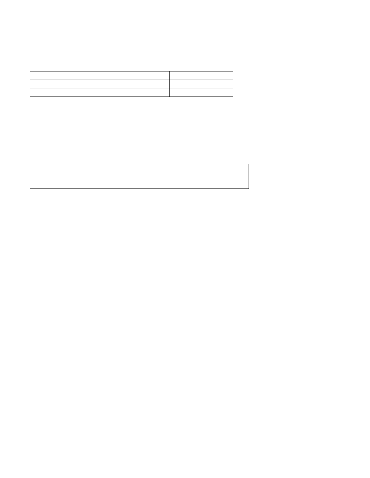
Function
Typical (ms)
Max (ms)
Read
5.9
7.3
Write
6.2
7.7
Rotational Speed
Time for a Revolution
(ms)
Average Latency
(ms)
15,030 RPM
3.992
1.996
4.4.1.2 Full Stroke Seek Time
Common to all models and all seek modes
Table 7 Full Stroke Seek Time
Full stroke seek is measured as the average of 1,000 full stroke seeks with a random head switch from both
directions (inward and outward).
4.4.1.3 Average Latency
Table 8 Latency Time
HGST Ultrastar C15K600 Hard Disk Drive Specification
28
Page 29
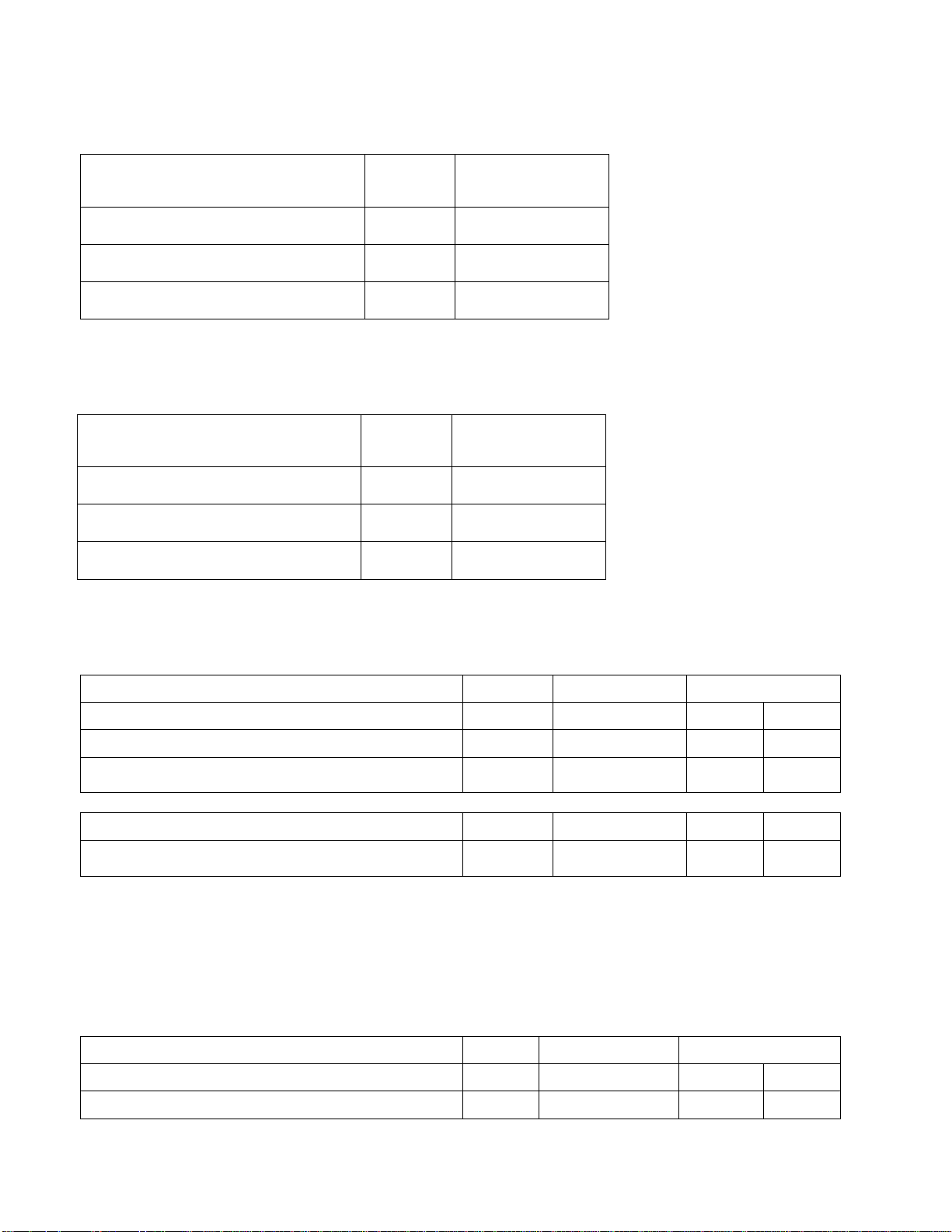
Model
Typical
(sec)
Maximum (sec)
600 GB Model (512n/4kn/512e)
9
15
450 GB Model (512n/4kn/512e)
7
15
300 GB Model (512n/4kn/512e)
6
15
Model
Typical
(sec)
Maximum (sec)
600 GB Model (512n/4kn/512e)
11
15
450 GB Model (512n/4kn/512e)
8
15
300 GB Model (512n/4kn/512e)
8
15
Description
Typical (MB / Sec)
Disk - buffer transfer
Zone
Model
Read
Write
Instantaneous
0
600/450/300 GB
267.0
267.0
Typical values for sustained disk - buffer transfer rate
0
600/450/300 GB
249.5
249.5
Instantaneous
39
600/450/300 GB
187.0
187.0
Typical values for sustained disk - buffer transfer rate
39
600/450/300 GB
174.7
174.7
Description
Typical (MB / Sec)
Disk - buffer transfer
Zone
Model
Read
Write
Instantaneous
0
600/450/300 GB
290.4
290.4
4.4.2 Drive Ready Time
Table 9 Drive Ready Time
4.4.3 Spindle Stop Time
Table 10 Spindle Stop Time
4.4.4 Data Transfer Speed
Table 11 Data Transfer Speed (sector size 512 Byte case)
Table 12 Data Transfer Speed (sector size 4096 Byte case)
HGST Ultrastar C15K600 Hard Disk Drive Specification
29
Page 30

Typical values for sustained disk - buffer transfer rate
0
600/450/300 GB
271.3
271.3
Instantaneous
39
600/450/300 GB
202.1
202.1
Typical values for sustained disk - buffer transfer rate
39
600/450/300 GB
188.8
188.8
Notes:
- For this table, '1 MB / Sec' is defined as 1,000,000 bytes per Second.
- Instantaneous disk-buffer transfer rate is derived by: (Number of sectors on a track) x (sectors/track) x
(revolutions/sec)
- The number of sectors per track will vary by radial zone because linear bit density is approximately constant
while track radius decreases with increasing zone number.
- Sustained disk-buffer transfer rate is the average rate measured while transferring multiple tracks of data.
It differs from the instantaneous transfer rate because of the time required to change tracks (track skew). In
addition, time is added for the occasional missed track switch.
4.4.5 Buffering Operation (read ahead/write cache)
This hard disk drive has a buffer for read ahead (see section 20.8 “Segmented Caching”)
This hard disk drive has a buffer for write cache (see section 20.6 “Write Cache”)
HGST Ultrastar C15K600 Hard Disk Drive Specification
30
Page 31

5 Data Integrity
The drive retains recorded information under all non-write operations.
No more than one sector can be lost by power down during a write operation while write cache is disabled. If power
down occurs before completion of a data transfer from write cache to disk while write cache is enabled, the data
remaining in the write cache will be lost. To prevent this data loss at power off, the following action is recommended:
- Confirm successful completion of a SYNCHRONIZE CACHE (35h) command
5.1 Equipment Status
Equipment status is available to the host system any time the drive is not ready to READ, WRITE or SEEK. This
status normally exists at power-on time and will be maintained until the following conditions are satisfied:
- Access recalibration/tuning is complete
- Spindle speed meets requirements for reliable operations
- Self-check of drive is complete
Appropriate error status is made available to the host system if any of the following conditions occur after the drive
has become ready:
- Spindle speed goes outside of requirements for reliable operation
- “Write fault” is detected
5.2 Error Recovery Procedure
- Errors occurring with the drive are handled by the error recovery procedure.
- Errors that are uncorrectable after application of the error recovery procedures are reported to the host
system as non-recoverable errors.
HGST Ultrastar C15K600 Hard Disk Drive Specification
31
Page 32

N N+1 N+2 N+3
defect defect
skip
skip
6 Physical Format
Media defects are remapped to the next available sector during the Format Process in manufacturing. The mapping
from Logical Block Address (LBA) to the physical Block locations is calculated using internally maintained tables.
6.1 Shipped Format (P-List)
- Data areas are optimally used.
- All pushes generated by defects are absorbed by available tracks of the inner notch.
P-List Physical Format
Note: Defects are skipped without any constraint, such as track or cylinder boundary. The calculation from LBA to
physical is done automatically by internal table.
6.2 Reassigned Format (G-List)
- G-List has a capacity of 4401 Customer LBAs.
- Multiple reassignments of the same Customer LBA increase the number of G-List entries.
- Spare sectors use the media cache regions which are inserted after every 1400 nominal customer tracks.
HGST Ultrastar C15K600 Hard Disk Drive Specification
32
Page 33

Pin No.
Signal
Description
S1
GND
GND for SAS Primary Port
S2
RP+
SAS Primary Port Receive (positive) signal
S3
RP-
SAS Primary Port Receive (negative) signal
S4
GND
GND for SAS Primary Port
S5
TP-
SAS Primary Port Transmit (negative) signal
S6
TP+
SAS Primary Port Transmit (positive) signal
S7
GND
GND for SAS Primary Port
S8
GND
GND for SAS Secondary Port
S9
RS+
SAS Secondary Port Receive (positive) signal
S10
RS-
SAS Secondary Port Receive (negative) signal
S11
GND
GND for SAS Secondary Port
S12
TS-
SAS Secondary Port Transmit (negative) signal
S13
TS+
SAS Secondary Port Transmit (positive) signal
S14
GND
GND for SAS Secondary Port
7 Electrical Interface
7.1 SAS Connector
The drive uses the standard 29 pin Serial Attached SCSI (SAS) connector which conforms to the mechanical
requirements of SFF 8680. The connector is expected to be used in an environment which uses a common
connector structure for racking disk drives in a cabinet. The connector allows for plugging a drive directly into a
backplane by providing the necessary electrical connection. Mechanical stability and device retention must be
provided by a mechanism outside the drive.
7.1.1 29 pin Serial Attached SCSI (SAS) Connector Definition
Diagram of top and bottom of connector showing pin outs.
Figure 1 SAS Connector
Table 13 29-pin Connector Signal Definition
HGST Ultrastar C15K600 Hard Disk Drive Specification
33
Page 34

P1
Vendor Spec
NOT USED (Pins P1-P2 tied internally)
P2
Vendor Spec
NOT USED (Pins P1-P2 tied internally)
P3
POWER
DISABLE
Power Disable
P4
GND
GROUND
P5
GND
GROUND
P6
GND
GROUND
P7
+5V-Charge
Pre-charge pin for +5V
P8
+5V
+5V power supply input
P9
+5V
+5V power supply input
P10
GND
GROUND
P11
READY LED
READY LED output
P12
GND
GROUND
P13
+12V=Charge
Pre-charge pin for +12V
P14
+12V
+12V power supply input
P15
+12V
+12V power supply input
7.1.2 Voltage and Ground Signals
The 12V and 5V contacts provide all of the voltages required by the drive. The two voltages share a common ground
plane to which all of the ground contacts are connected.
7.1.3 Ready LED Output
The drive provides an open-drain driver with 15mA of current sink capability to the Ready LED Output signal. The
cathode of the LED should be connected to this signal. The LED and the current-limiting resistor must be provided by
the enclosure
HGST Ultrastar C15K600 Hard Disk Drive Specification
34
Page 35

Operating Conditions
Ambient Temperature
5°C to 55ºC
Relative humidity
5 to 90%, non-condensing
Maximum wet bulb temperature
29.4ºC, non-condensing
Maximum surface temperature gradient
20ºC/hour
Altitude
-305 to 3,048 m
Shipping Conditions
Ambient Temperature
-40°C to 70ºC
Relative humidity
5 to 95%, non-condensing
Maximum wet bulb temperature
35ºC, non-condensing
Maximum surface temperature gradient
30ºC/hour
Altitude
-305 to 12,192 m
Storage Conditions
Ambient Temperature
0°C to 65ºC
Relative humidity
5 to 90%, non-condensing
Maximum wet bulb temperature
35ºC, non-condensing
Altitude
-305 to 12,192 m
8 Environment
8.1 Temperature And Humidity
Table 14 Operating and Non-operating Conditions
Environments that contain elevated levels of corrosives (e.g. hydrogen sulfide, sulfur oxides, or hydrochloric acid)
should be avoided. Care must be taken to avoid using any compound/material in a way that creates an elevated
level of corrosive materials in the atmosphere surrounding the disk drive. Care must also be taken to avoid use of
any organometallic (e.g. organosilicon or organotin) compound/material in a way that creates elevated vapor levels
of these compounds/materials in the atmosphere surrounding the disk drive.
HGST Ultrastar C15K600 Hard Disk Drive Specification
35
Page 36

Figure 2 Environmental Specification
8.2 Storage Requirements
8.2.1 Packaging
The drive or option kit must be heat-sealed in a moisture barrier bag with bag supplied by HGST.
8.2.2 Storage Time
The drive may not remain inoperative for a period of more than one year. During this time, the maximum time the
drive may be stored after the bag is opened is 6 months.
HGST Ultrastar C15K600 Hard Disk Drive Specification
36
Page 37

Module name
Location
Maximum allowable surface
temperature
HDD base casting
as noted in
picture
60ºC
8.3 Cooling Requirements
Drive component temperatures must remain within the limits specified in the following table. Maximum component
temperature ratings must not be exceeded under any operating condition. The drive may require forced air cooling to
meet the specified, maximum operating temperatures.
Table 15 Maximum Allowable Surface Temperatures
HGST Ultrastar C15K600 Hard Disk Drive Specification
37
Page 38

Supply
Tolerance
Absolute Max
Spike Voltage
Supply Rise Time
Capacitance
5 V
+/- 5%
5.5 V
0-200 ms
51 uF
12 V
+/- 5%
15 V
0-400 ms
14 uF
9 DC Power Requirements
The following voltage specification applies at the drive power connector. Connections to the drive should be made in
a safety extra low voltage (SELV) circuit. There is no power on or power off sequencing requirement.
Adequate secondary over-current protection is the responsibility of the system.
Table 16 Input Voltage and Capacitance
Note: -8% is acceptable during spin up, but the spin up time is not guaranteed.
HGST Ultrastar C15K600 Hard Disk Drive Specification
38
Page 39

9.1 Power Supply Current, Average and Peak
The following current and power requirements are typical when operating under the following conditions: Nominal 5
and 12V, Background Media Scan (BMS) disabled for Idle, Write Caching disabled and the drive reporting a
temperature of 45C, unless noted. Power On to Drive Ready is measured at 25C.
Figure 3 Current and Power Requirements
HGST Ultrastar C15K600 Hard Disk Drive Specification
39
Page 40

Table 17 600 GB, 4K
Table 18 600 GB, 512
HGST Ultrastar C15K600 Hard Disk Drive Specification
40
Page 41

Table 19 450 GB, 4K
Table 20 450 GB, 512
HGST Ultrastar C15K600 Hard Disk Drive Specification
41
Page 42

Table 21 300 GB, 4K
Table 22 300 GB, 512
HGST Ultrastar C15K600 Hard Disk Drive Specification
42
Page 43

Maximum (mV pp)
MHz
+5 V DC
250
0-10
+12 V DC
250
0-10
Figure 4 Power vs IOPS
9.2 Ripple Voltage
Table 23 Power Supply Generated Ripple at Drive Power Connector
During drive start up and seek, 12 volt ripple is generated by the drive (referred to as dynamic loading). If the power
of several drives is daisy chained, the power supply ripple plus other drive dynamic loading must remain within the
regulation tolerance of +5%. A common supply with separate power leads to each drive is a more desirable method
of power distribution.
To prevent external electrical noise from interfering with the drive's performance, the drive must be held by four
screws in a user system frame that has no electrical level difference at the four screw positions. The drive
enclosure must not be used in the current return path of the drive power supply. The maximum common-mode
noise current passing through the drive must not exceed 20 mA.
HGST Ultrastar C15K600 Hard Disk Drive Specification
43
Page 44

Model
Idle_W
GB
Value
600
5.8
600
0.0096
450
5.1
450
0.0113
300
5.0
300
0.0168
9.3 Power Consumption Efficiency Index
Table 24 Power Consumption Efficiency Index
HGST Ultrastar C15K600 Hard Disk Drive Specification
44
Page 45

10 Reliability
10.1 Start/Stop Cycles
The drive is designed to withstand a minimum of 50,000 start/stop cycles at ambient environment.
The drive is designed to withstand a minimum of 10,000 start/stop cycles at the operating environment conditions
specified in Chapter 8.0, “Environment”.
10.2 Load/Unload Cycles
The drive is designed to withstand a minimum of 600,000 load/unload cycles at the operating environmental
conditions specified in Chapter 8.0, “Environment”.
10.3 Data Reliability
The probability of an uncorrectable data error on a population average is 10 in 1x1017 bits read.
The channel design is changed from the prior generation of DASD devices to use an LDPC channel having similar
code rate to prior Reed Solomon error correction. The design of the LDPC channel includes usage of media defect
detection circuits for locating defects and performing erasure correction, replacing the offline erasure correction
capability of RS codes. Modulation coding properties for timing and gain recovery are equivalent to prior product
generation
LDPC implementation:
- Single LDPC codeword per sector with 576 bits of parity for 512n (4kB format LDPC overhead is 4608 which
is exactly 8*576)
- Media defect detection circuit using erasure flags to zero LLR values
- LDPC code designed to correct defects up to 425 bits for 512n
- LBA seeded 32 bit CRC on the sector, plus a 72 bit media ECC for miscorrect detection
10.4 Seek Errors
A non-recoverable seek/ID miscompare error is defined as a seek operation that cannot be recovered by the error
recovery procedure of the drive. The drive reports sense key 04 and sense code 02 for this error.
No drive has more than ten non-recoverable seek/ID miscompare error per 100 million seek operations (<10 in 1x
108) when operated at the full range of voltage and environmental conditions.
10.5 Failure Prediction (S.M.A.R.T)
SMART Monitoring Parameters are checked to determine if the (Read/Write/Seek) error rates exceed the drive’s
threshold value when an error occurs and a minimum amount of operation has been completed. A check is also
performed for a minimum level of Spare Sector Availability.
The Head Load / Unload Count, Spin Up Time and Spin Up Retry Count parameters are checked prior to reporting a
“Ready” condition at Power On. Smart monitors Milliactuator calibration which occurs at power on and in error
recovery. SMART monitors unrecoverable corrupted critical segments of the Reserved Area. If SMART reports a
problem in the Reserved Area, all data should be recovered from the drive before a power cycle.
HGST Ultrastar C15K600 Hard Disk Drive Specification
45
Page 46

10.6 MTBF (Mean Time Between Failure): 2.0M hours.
This MTBF target is based on a sample population and is estimated by statistical measurements and acceleration
algorithms under nominal operating conditions. MTBF ratings are not intended to predict an individual drive’s
reliability. MTBF does not constitute a warranty.
10.7 Preventive Maintenance
None
10.8 Temperature Warning
Temperature Warning is enabled by setting the EWASC (Enable Warning Additional Sense Code) bit to 1 and
setting DEXCPT (Disable Exception Control) bit to 0 in Mode Page 1C. For mode page settings, refer to Section
“Mode Page 1C (Informational Exceptions Control)”. The warning is issued as sense data (Sense Key 01h, Code
0Bh, Qual 01h).
The drive temperature is reported in “Log Sense Page 2F”.
HGST Ultrastar C15K600 Hard Disk Drive Specification
46
Page 47

Height [mm]
14.75 ± 0.25
Width [mm]
69.85 ± 0.25
Length (base) [mm]
100.2 ± 0.25
Length (including connector) [mm]
100.6 ± 0.7
Weight [grams - maximum]
600 GB Model 221 grams
450/300 GB Model 215 grams
11 Mechanical Specifications
11.1 Outline
11.2 Mechanical Dimensions
The drive complies with SFF-8201.
Table 25 Physical Dimensions
HGST Ultrastar C15K600 Hard Disk Drive Specification
47
Page 48

Figure 5 Top and Side Views and Mechanical Dimensions
All dimensions are in millimeters.
HGST Ultrastar C15K600 Hard Disk Drive Specification
48
Page 49

11.3 Interface Connector
The interface conforms to the specification SFF-8223, 2.5 Drive Form Factor with Serial Connector.
11.4 Mounting Positions and Tappings
HGST Ultrastar C15K600 Hard Disk Drive Specification
49
Page 50

11.5 Drive Mounting
The drive will operate in all axes (6 directions). Performance and error rate will stay within specification limits if the
drive is operated in the other orientations from which it was formatted.
The recommended mounting screw torque is 0.45 Nm (4.5 Kgf-cm). The recommended mounting screw depth is 2.5
mm maximum for bottom and 3.0 mm maximum for horizontal mounting.
To avoid performance degradation, mount the drive in the system securely enough to prevent excessive motion or
vibration of the drive at seek operation or spindle rotation, using appropriate screws or equivalent mounting
hardware. Consult with the issuer of this specification for actual application if necessary.
Drive level vibration tests and shock tests are to be conducted with the drive mounted to a table using the bottom
four screws.
11.6 Heads Unload and Actuator Lock
Heads are moved out from the disks (unload) to protect the disk data during shipping, moving or storage. At power
down, the heads are automatically unloaded from over the disk area and the head actuator locking mechanism will
secure the heads in the unload position.
HGST Ultrastar C15K600 Hard Disk Drive Specification
50
Page 51

12 Vibration and Shock
All vibration and shock measurements in this section are made with a bare drive. The input for the measurements
are applied to the normal drive mounting points unless noted otherwise.
12.1 Operating Vibration
12.1.1 Random Vibration
The drive is designed to operate without unrecoverable errors while being subjected to the vibration levels as defined
below.
The assessments are carried out during 30 minutes of random vibration using the power spectral density (PSD)
levels as follows.
No Errors: 0.4 G RMS, 5-500 Hz, flat PSD profile for each of the three mutually perpendicular axes.
No Data Loss: 1.2 G RMS, 5-500 Hz, flat PSD profile for each of the three mutually perpendicular axes.
No Data Loss: 1.5 G RMS, 10-300 Hz for each of the three mutually perpendicular axes.
Note: The specified levels are measured at the mounting points.
12.1.2 Swept Sine Vibration
The drive will meet the criterion while operating in the respective conditions as described below.
No errors: 1.0g @ 5-500 Hz sine wave, 0.5 octave/minute sweep rate
No data loss: 1.5g @ 5-500 Hz sine wave, 0.5 octave/minute sweep rate
12.2 Non-operating Vibrations
The drive will not sustain permanent damage or loss of recorded data after being subjected to the environments as
described below
12.2.1 Random Vibration
The test consists of a random vibration applied for each of the three mutually perpendicular axes. A time duration
of ten minutes per axis.
1.5 G RM S, 5-500 Hz, flat PSD profile.
12.2.2 Swept Sine Vibration
The test consists of a swept sine vibration applied for each of the three mutually perpendicular axes.
3.0 G 0-peak, 10 - 500 Hz sine wave, 0.5 octave/minute sweep rate.
12.3 Operating Shock
The drive will meet the criterion while operating in the respective conditions as described below.
No data loss: 15G, 11 ms duration, half sinewave shock pulse
No data loss: 60G, 2 ms duration, half sinewave shock pulse, read operation mode
No data loss: 30G, 2 ms duration, half sinewave shock pulse, write operation mode
HGST Ultrastar C15K600 Hard Disk Drive Specification
51
Page 52

The shock pulses of each level are applied to the drive, ten pulses for each direction and for all three mutually
perpendicular axes. There must be a minimum of thirty seconds delay between shock pulses. The input level is
applied to a base plate where the drive is attached using four mounting screws.
12.4 Non-operating Shock
The drive will not sustain permanent damage or loss of recorded data after being subjected to the environments as
described below.
12.4.1 Half sinewave Shock Pulse
100 G, 11 ms duration, half sinewave pulse
300 G, 2 ms duration, half sine wave pulse
200 G, 0.5 ms duration, half sinewave pulse
The shocks are applied in each direction of the drive for the three mutually perpendicular axes, one axis at a time.
The input level is applied to a base plate where the drive is attached using four mounting screws.
12.4.2 Rotational Shock
30,000 radians /second2, 1 ms duration
20,000 radians /second2, 2 ms duration
The shock input is applied around the axis of the actuator pivot. The shock input does not displace the heads from
the actuator latched position.
HGST Ultrastar C15K600 Hard Disk Drive Specification
52
Page 53

Model
Mode
A-weighted Sound Power Level (Bel)
Typical
Maximum
300, 450, 600 GB
Idle
3.2
3.4
Operating
3.8
4.1
13 Acoustics
13.1 Sound Power Levels
The upper limit criteria of A-weighted sound power levels are given in Bel, relative to one pico watt, and are shown in
the following table. The measurement method is in accordance with ISO-7779.
Table 26 A-weighted Sound Power Levels
Background power levels of the acoustic test chamber for each octave band are to be recorded. Sound power levels
are measured with the drive supported by spacers so that the lower surface of the drive is located at a height of 25
cm from the chamber floor.
No sound-absorbing material shall be used. The acoustical characteristics of the drive subsystem are measured
under the following conditions.
Idle Mode:
Powered on, disks spinning, track following, unit ready to receive and respond to host commands.
Operating Mode
Continuous random cylinder selection and seek operation of the actuator with dwell time at each cylinder. Seek rate
for the drive is calculated per the formula below:
Ns = average seek rate in seeks/sec where:
Ns = 0.4 / (Tt + Tl)
Tt = published random seek time
Tl = time for the drive to rotate by half a revolution
HGST Ultrastar C15K600 Hard Disk Drive Specification
53
Page 54

14 Identification Labels
14.1 Labels
The following labels are affixed to every hard disk drive shipped from the drive manufacturing location in accordance
with appropriate hard disk drive assembly drawing:
A label containing the HGST logo, HGST part number and the statement “Made by HGST,” or HGST
approved equivalent.
A label containing drive model number, manufacturing date, formatted capacity, country of origin or HGST
approved equivalent and UL, C-UL, TUV, CE, MIC, BSMI,CTICK, RoHS and Recycle logos.
A bar code label containing the drive serial number.
A user designed label, per agreement
Interface definition mark, SAS-3 Model
The labels may be integrated with other labels.
HGST Ultrastar C15K600 Hard Disk Drive Specification
54
Page 55

15 Electromagnetic Compatibility
The drive, when installed in a suitable enclosure and exercised with a random accessing routine at a maximum data
rate will comply with the worldwide EMC requirements listed below.
The drive is designed for system integration and installation into a suitable enclosure for use. As such, the drive is
supplied as a subassembly and is not subject to Subpart B of Part 15 of the FCC Rules and Regulations.
The design of the drive serves to minimize radiated emissions when installed in an enclosure that provides
reasonable shielding. As such, the drive is capable of meeting FCC Class B limits. However, it is the user’s
responsibility to assure that the drive meets the appropriate EMC requirements in their system. Shielded I/O cables
may be required if the enclosure does not provide adequate shielding, with the shields grounded to the enclosure
and to the host computer.
Radiated and Conducted RF
CISPR22:2009/Am1:2010 (Australia, New Zealand)
CNS 13438:2006 (Taiwan)
EN 55022:2010 (EU)
FCC Title 47 Part 15 (USA)
GB9254-2008 (China)
ICES-003, Issue 5, 2012 (Canada)
VCCI V-3/2013-04 (Japan)
KN 22:2013-3 (RRA Notice) (Korea)
KN 22:2013-24 (RRA Notice) (Korea)
ITE Immunity
EN 55024:2010 (EU)
KN 24:2013-4 (RRA Notice) (Korea)
KN 24:2013-25 (RRA Notice) (Korea)
Power Line Harmonic Emissions
EN 61000-3-2:2006 Am1:2009, Am2:2009 (EU)
GB 17625.1 2003 (China)
Voltage Fluctuations and Flicker
EN 61000-3-3:2008 (EU)
GB 17625.2 1999 (China)
Electrostatic Discharge (ESD) Immunity
KN 61000-4-2:2013-06
Radiated RF Immunity
HGST Ultrastar C15K600 Hard Disk Drive Specification
55
Page 56

KN 61000-4-3:2011-10
Electrical Fast Transient/Burst (EFT/B) Immunity
KN 61000-4-4:2011-10
Surge Immunity
KN 61000-4-5:2008-05
Conducted RF Immunity
KN 61000-4-6:2013-06
Power Frequency Magnetic Field Immunity
KN 61000-4-8:2013-06
Voltage Dips and Interruptions Immunity
KN 61000-4-11:2008-05
15.1 Class B Regulatory Notices
European Union
This product is in conformity with the protection requirements of EU Council Directive 2004/108/EC on the
approximation of the laws of the Member States relating to electromagnetic compatibility. HGST cannot accept
responsibility for any failure to satisfy the protection requirements resulting from a non-recommended modification of
the product, including the fitting of non-HGST option cards.
This product has been tested and found to comply with the limits for Class B Information Technology Equipment
according to European Standard EN 55022. The limits for Class B equipment were derived for typical residential
environments to provide reasonable protection against interference with licensed communication devices.
Canada
This Class B digital apparatus complies with Canadian ICES-003.
Cet appareil numérique de la classe B est conforme à la norme NMB-003 du Canada.
Germany
Deutschsprachiger EU Hinweis:
Hinweis für Geräte der Klasse B EU-Richtlinie zur Elektromagnetischen Verträglichkeit Dieses Produkt entspricht
den Schutzanforderungen der EU-Richtlinie 2004/108/EC zur Angleichung der Rechtsvorschriften über die
elektromagnetische Verträglichkeit in den EU-Mitgliedsstaaten. und hält die Grenzwerte der EN 55022 Klasse B ein.
Um dieses sicherzustellen, sind die Geräte wie in den Handbüchern beschrieben zu installieren und zu betreiben.
Des Weiteren dürfen auch nur von der HGST empfohlene Kabel angeschlossen werden. HGST übernimmt keine
Verantwortung für die Einhaltung der Schutzanforderungen, wenn das Produkt ohne Zustimmung der HGST
verändert bzw. wenn Erweiterungskomponenten von Fremdherstellern ohne Empfehlung der HGST
gesteckt/eingebaut werden.
HGST Ultrastar C15K600 Hard Disk Drive Specification
56
Page 57

Deutschland: Einhaltung des Gesetzes über die elektromagnetische Verträglichkeit von Geräten
Dieses Produkt entspricht dem "Gesetz über die elektromagnetische Verträglichkeit von Geräten (EMVG)". Dies ist
die Umsetzung der EU-Richtlinie 2004/108/EC in der Bundesrepublik Deutschland.
Zulassungsbescheinigung laut dem Deutschen Gesetz über die elektromagneti-sche Verträglichkeit von Geräten
(EMVG) vom 20 July 2007 (bzw. der EMC EG Richtlinie 2004/108/EC) für Geräte der Klasse B Dieses Gerät ist
berechtigt, in Übereinstimmung mit dem Deutschen EMVG das EG-Konformitätszeichen - CE - zu führen.
Verantwortlich für die Konformitätserklärung nach Paragraf 5 des EMVG ist die HGST, a Western Digital company,
3403 Yerba Buena Road, San Jose, California 95135. Informationen in Hinsicht EMVG Paragraf 4 Abs. (1) 4:
Das Gerät erfüllt die Schutzanforderungen nach EN 55024 und EN 55022 Klasse B.
Korea (MIC)
Taiwan (BSMI)
HGST Ultrastar C15K600 Hard Disk Drive Specification
57
Page 58

Component
Flammability Rating
Rigid Printed Wiring Board
Min. V-1
Flex Cable - no components
Min. V-2
Interface & motor connectors
Min. V-2
16 Safety Certification
The following shows the safety standards for different countries.
16.1 UL and CSA Standard Conformity
This drive is used as a component in Information Technology Equipment (ITE) business equipment systems. This
drive is certified for use in the United States per UL 60950-1, Second Edition, 2011-12-19 and in Canada per CSA
C22.2 No. 60950-1-07, Second Edition, 2011-12. The cRUus UL component recognition mark is specifically used on
component parts that are part of a larger product or system and indicates compliance with both Canadian and U.S.
requirements. The recognition mark appears on the drive label and is maintained for the life of the product.
16.2 European Standards Compliance
This product is additionally certified to the following standard:
International Electrotechnical Commission (IEC) Safety Standard:
IEC 60950-1:2005, Second Edition + A1:2009 (IECEE CB Scheme)
16.3 German Safety Mark
This product has received the TUV Bauart Certification mark under EN 60950-1:2006 with Am. 11 (2009) +
Am1:2010 + A12:2011, Second Edition safety standard. The GS mark is not applicable to internal subsystem drives.
16.4 Flammability
The printed wiring boards, flex cables, and connectors used in this drive meet or exceed the UL minimum
flammability classifications listed in the table below.
The flammability ratings are marked on the printed wiring boards and flex cables
16.5 Corporate Standards Compliance
This product has been designed to meet the following Corporate Standards:
- NB 3-0501-201 Product Safety, National Requirements-All Countries.
- CS 3-0501-070 Electrical, Mechanical and Flammability
- NB 3-0501-033 Product Safety National Certification Conformity Requirement
- CS 9700-020 Eco-Product Design Requirement
HGST Ultrastar C15K600 Hard Disk Drive Specification
58
Page 59

17 SAS Attachment
This section defines some basic terminology and describes the behavior of the drive when attached to a Serial
Attached SCSI (i.e. SAS) domain.
17.1 General
This section introduces some of the terminology that is used in describing Serial Attached SCSI (i.e. SAS).
SAS is logically a bi-directional, point to point serial data channel that leverages the SCSI protocol set. Nodes are
physically connected via a port.
Ports may be connected point-to-point via SAS expanders, to form a complex switching network, referred to as a
SAS domain.
SAS is defined in terms of a hierarchy of functions or 'protocol layers'. This discussion will focus in on the aspects of
SAS that are relevant to this product.
• SCSI Application Layer - Clause 10
• SSP Transport Layer (Serial SCSI Protocol) - Clause 9
• SAS Port Layer - Clause 8
• SSP Link Layer - Clause 7
• SAS PHY Layer - Clause 6
• SAS Physical Layer - Clause 5
All layers are defined in the following ANSI standard.
• "SAS Protocol Layer - 2 (SPL-3)"
In addition, this drive claims compliance with the following ANSI standards.
• SCSI Architecture Model (SAM-5)
• SCSI Block Commands (SBC-3)
17.2 SAS Features
The following SAS features are supported by the drive.
• SAS Compliance
- "Serial Attached SCSI - 3 (SAS-3)"
• SAS Protocol
- This drive supports Serial SCSI Protocol (SSP).
- STP (Tunneled SATA) and SMPs (Management protocols) are NOT supported.
HGST Ultrastar C15K600 Hard Disk Drive Specification
59
Page 60

• SAS Dual Ported Operation
- Single PHY ports (i.e. Narrow port. Wide Port NOT supported)
- Ports function independently with separate firmware controls
- Multiple DMA engines capable of accessing either port
- Maximum outstanding credit of four per port
• Physical Link Rates
- G1 (1.5 Gbs), G2 (3.0 Gbps), G3 (6.0 Gbps), and G4 (12.0 Gbps) supported
- Largely automated OOB and speed negotiation sequences
- Optional support for the hot-plug timeout in hardware
• Partial support for Disconnect/Reconnect Mode Page (0x02)
- Maximum Connect Time Limit - SUPPORTED
- Bus Inactivity Time Limit - NOT SUPPORTED
- Maximum Burst Size - SUPPORTED
- First Burst Size - NOT SUPPORTED
• Others...
- Connection Rate Matching
- Hard Reset primitive sequence detection and validation in hardware
- Support for NOTIFY (Power Loss Expected)
- Hashed WWN validation in hardware
- Extended CDB support
HGST Ultrastar C15K600 Hard Disk Drive Specification
60
Page 61

Object
SAS Implementation
Port Identifier
SAS address
Port Name
Not defined
Device Name
SAS address
PHY Identifier
PHY identifier
Byte/Bit
7 6 5 4 3 2 1 0 0
NAA (5h)
(MSB)
1
IEEE Company ID
2
3
(LSB)
(MSB)
4
Vendor Specific Identifier
(LSB)
5
6
7
Bit
63-60
59-36
35-24
23-2
1-0
0101
OUI in Canonical Form
Block Assignment
S/N
Object
17.3 SAS Names and Identifiers
In SAS, device and port names are worldwide unique names within a transport protocol. Port identifiers are the
values by which ports are identified within a domain, and are used as SAS addresses. PHY identifiers are unique
within a device.
Table 27 Names and Identifiers
Where the SAS address format is defined by ANSI as follows:
Table 28 SAS Address Format
The SAS device name is a unique SAS address worldwide name. This device name is reported through the SCSI
Vital Products Data.
Each of the two SAS ports also has a unique SAS address worldwide name. These port identifiers are reported in the
IDENTIFY address frame and are used as source and destination addresses in the OPEN address frame. They are
also reported through the SCSI Vital Products Data.
Since this drive is one device with two ports it has three SAS addresses. All SAS addresses are in 64-bit IEEE
Registered Name format, as illustrated in Table 29.
Table 29 IEEE Registered Name Format
HGST Ultrastar C15K600 Hard Disk Drive Specification
61
Page 62

Field
Description
OUI
Organizationally Unique Identifier (24 bits). Canonical form means that each byte is stored
in “bit reversed” order.
Block Assignment
Block assignment within HGST, a Western Digital Company
Object
Device Name/Port Identifier
00b Device
01b Port 1
10b Port 2
11b Not assigned
S/N
Sequentially increasing drive serial number assigned at manufacturing.
The Name Address Authority field (5h) specifies the format used for the rest of the name as follows:
HGST Ultrastar C15K600 Hard Disk Drive Specification
62
Page 63

Link Reset Sequence with hard Reset
Time
Phy Reset sequence
Identification sequence
Phy Reset sequence Hard Reset Sequence
Phy Reset sequence Identification sequence
Time
SAS
SAS w/Hard Reset
Link Reset sequence
OOB sequence Speed Negotiation
sequence
17.4 PHY Layer
The PHY layer defines 8b10b encoding and OOB signals. The PHY layer is the interface between the link layer and
the physical layer. This section describes PHY layer behaviors of the drive. For a complete description of SAS PHY
Layer, please see the ANSI specification, SPL-3.
17.4.1 Link Reset Sequence
The Link Reset sequences for SAS are defined in the SPL-3 ANSI specification with a general overview shown
below. As shown in the diagram, a PHY Reset sequence, consists of an OOB sequence, followed by speed
negotiation. Link Reset sequences will always include a PHY Reset sequence, followed by an Identification
sequence. Inclusion of a Hard Reset sequence is optional. If Hard Reset is performed, it will be preceded by a PHY
Reset sequence, and followed by PHY Reset and an Identification sequence.
Figure 6 Link Reset Sequence
HGST Ultrastar C15K600 Hard Disk Drive Specification
63
Page 64

17.4.2 Hard Reset
A Hard Reset sequence on a port will not affect the other port, but the outstanding commands on the other port will
be aborted due to the LUN reset associated with the Hard Reset. The effect of a Hard Reset will be similar to a
Power on Reset, and will result in the re-initialization of all drive resources. The first command issued from every
initiator on the port that received the Hard Reset will result in a CHECK CONDITION with a sense key of UNIT
ATTENTION and an additional sense code of SCSI BUS RESET OCCURRED. The first command issued from
every initiator on the other port will result in a CHECK CONDITION and an additional sense code of BUS DEVICE
RESET OCCURRED.
A Hard Reset sequence will never be issued by the drive. A link reset will be initiated by the drive on the affected port
upon completion of Hard Reset processing.
17.4.3 SAS OOB (Out of Band)
Out of Band (OOB) signals are low-speed signal patterns detected by the PHY that do not appear in normal data
streams. They consist of defined amounts of idle time followed by defined amounts of burst time. During the idle
time, D.C. idle is transmitted. During the burst time, ALIGN (0) primitives are transmitted repeatedly. The signals are
differentiated by the length of idle time between the burst times.
As a SAS compliant device, the drive uses three OOB signals: COMINIT/COMRESET and COMWAKE and
COMSAS.OOB operations are beyond the scope of this specification. Please refer to the ANSI SPL-3 specification
for more details.
The drive will initiate OOB by sending COMINITs, under the following conditions:
- POR
- Loss of sync
- Identify timeout
HGST Ultrastar C15K600 Hard Disk Drive Specification
64
Page 65

Byte /Bit 7 6 5 4 3 2 1 0
0
Start =1b
TX SSC
Type = 0b
Reserved
Requested Logical Link Rate = 0h
1
G1 Without
SSC=1b
G1 With
SSC=1b
G2 Without
SSC=1b
G2 With
SSC=1b
G3 Without
SSC=1b
G3 With
SSC=1b
G4
Without
SSC=1b
G4 With
SSC=1b
2
Reserved
3
Reserved
Parity
Priority
Bit
Highest
G4 With SSC bit
...
G4 Without SSC bit
...
G3 With SSC bit
...
G3 Without SSC bit
...
G2 With SSC bit
…
G2 Without SSC bit
17.4.4 SAS Speed Negotiation
The drive supports G1 (1.5 Gbps), G2 (3.0 Gbps), G3 (6.0 Gbps), and G4 (12.0 Gbps) negotiation speeds. The
default maximum negotiation rate is G4 speed (per byte 32 in the PHY Control and Discover Mode Page 19 subpage
1). Drive is SAS3 device and supports SNW-1, SNW-2, SNW-3 speed negotiation with PHY capabilities exchange,
and both transmitter training (Train_Tx-SNW, at 12G only) and receiver training (Train_Rx-SNW or Train-SNW). The
drive’s PHY capabilities are defined in table below:
PHY Capabilities:
Table 30 SAS Speed Negotiation
Start is set to 1 to indicate the beginning of the PHY capabilities
TX SSC Type is set to 1 to indicate that PHY’s transmitter uses center-spreading-SSC when SSC is enabled
TX SSC Type is set to 0 to indicate that PHY’s transmitter uses down-spreading-SSC when SSC is enabled
Requested Logical Link Rate field is set to 0 to indicate that drive does not support multiplexing
G1 Without SSC is set to 1 to indicate that drive supports G1 (1.5 Gbps) without SSC
G2 Without SSC is set to 1 to indicate that drive supports G2 (3.0 Gbps) without SSC
G3 Without SSC is set to 1 to indicate that drive supports G3 (6.0 Gbps) without SSC
G4 Without SSC is set to 1 to indicate that drive supports G4 (12.0 Gbps) without SSC
G1 With SSC set to 1 to indicate that drive supports G1 (1.5 Gbps) with SSC
G2 With SSC set to 1 to indicate that drive supports G2 (3.0 Gbps) with SSC
G3 With SSC set to 1 to indicate that drive supports G3 (6.0 Gbps) with SSC
G4 With SSC is set to 1 to indicate that drive supports G4 (12.0 Gbps) with SSC
Parity is set to 1 for even parity of the total number of SNW-3 PHY capabilities, including Start bit.
Training is based on the highest untried commonly supported settings on the exchanged SNW-3 supported settings
bits. If a Train-SNW is invalid and there are additional, untried, commonly supported settings exchanged during
SNW-3, then a new Train-SNW will be performed based on the next highest untried, commonly supported settings.
Table 31 defines the priority of the supported settings bits.
Table 31 Supported Settings Bit Priorities
HGST Ultrastar C15K600 Hard Disk Drive Specification
65
Page 66

…
G1 With SSC bit
G1 Without SSC bit
Lowest
HGST Ultrastar C15K600 Hard Disk Drive Specification
66
Page 67

Error
Error Handling Procedure
Link Reset
After POR or Hard Reset, the drive initiates link reset by transmitting exactly 1
COMINIT. For other resets, the drive does not initiate Link Reset.
COMINIT Timeout
If COMINIT or COMSAS is not received before the ”Hot Plug Timeout" period
expires, the drive continues to transmit DC zero and wait for COMINIT/COMSAS.
Firmware is notified.
This is not considered an error.
COMSAS Timeout
If COMINIT is detected, COMSAS is transmitted, and COMSAS is not received
before the COMSAS Detect Timeout timer expires, firmware is notified and the
drive continues to transmit DC zero and wait for COMINIT.
Speed Negotiation Errors
If speed negotiation fails with no match, or if the drive fails retrying the matched
link rate, firmware is notified and the drive continues to transmit DC zero and wait
for COMINIT. If the match link rate retry fails, the PHY Reset Problem counter is
incremented (Log Page 0x18).
Loss of Sync
If the drive loses Dword sync long enough for the loss of sync timer to expire,
firmware is notified and the drive transmits a COMINIT to initiate a new link reset.
The loss of Dword sync counter is incremented (Log Page 0x18).
Disparity/Invalid Dword Error
If a disparity error or an invalid Dword is detected by the drive, the Invalid Dword
Count is incremented (Log Page 0x18). The Running Disparity Error Count in Log
Page 0x18 is not used
17.4.5 PHY Error Handling
This section defines the PHY layer error handling of the drive.
Table 32 PHY Layer Error Handling
HGST Ultrastar C15K600 Hard Disk Drive Specification
67
Page 68

Byte
Bit
7 6 5 4 3 2 1
0
0
RSVD
Device Type
Address Frame Type
1-27
Frame Type Dependent bytes
28-31
CRC
Value
Address Frame Type Description
0000b
IDENTIFY: Identification Sequence
0001b
OPEN: Connection Request
Others
Reserved
17.5 Link Layer
The SAS Link layer defines primitives, address frames, and connections. The Link layer is the interface between the
Port layer and the PHY layer. This section describes Link layer behaviors of the drive. For a complete description of
SAS Link layer, please see the ANSI specification, SPL-3.
17.5.1 Address Frames
Address frames are used for the identification sequence and for connection requests and are only sent outside
connections. The Address Frame format is defined below:
Table 33 Address Frame Format
Address Frame Type indicates the type of address frame and is defined in Table 34. This field determines the
definition of the frame type dependent bytes.
Table 34 Frame Type:
HGST Ultrastar C15K600 Hard Disk Drive Specification
68
Page 69

Byte
Bit
7 6 5 4 3 2 1
0
0
RSVD
Device Type = 1h
Address Frame Type = 0
1
Reserved
Reason
2
Reserved
SSP
Initiator
Port
STP
Initiator
Port
SMP
Initiator
Port
RSVD
3
Reserved
SSP
Target Port
STP
Target
Port
SMP
Target
Port
RSVD
4-11
Device Name
12-19
SAS Address
20
PHY Identifier
21
Persistent
Capable
Power Capable
Slumber
Capable
Partial
Capable
Inside
ZPSDS
Persistent
Requested
Inside
ZPSDS
Break_Repl
y
Capable=1b
22
Pwr_DIS
Capable
23-27
Reserved
28-31
CRC
17.5.1.1 Identify Address Frame
The Identify Address Frame format is used for the identification sequence. The Identify Address Frame is sent after
the PHY reset sequence completes. The Identify Address Frame format is defined as follows:
Table 35 Identify Address Frame
Device Type is set to 001b to indicate that this drive is an "End Device"
Address Frame Type is set to 00b to indicate that this is an IDENTIFY
Reason indicates the reason for link reset sequence as defined in Table 36
Initiator Port bits is set to 000b since this device is a target device only
Target Port bits is set to 100b since this device is a SSP target device only
Device Name contains Target Device Identifier
SAS Address contains the port identifier of the SAS port transmitting this frame
PHY Identifier contains the PHY identifier of the PHY transmitting this frame
Persistent Capable is set to 0b to indicate the drive does not support persistent connections
Power Capable is set to 00b to indicate drive does not issue PWR_REQ or PWR_DONE, and does not respond
Slumber Capable is set to 0b to indicate drive does not support slumber power PHY mode
Partial Capable is set to 0b to indicate drive does not support partial power PHY mode
Inside ZPSDS Persistent: set to 0b since this is an "End Device"
to PWR_GRANT
HGST Ultrastar C15K600 Hard Disk Drive Specification
69
Page 70

Requested Inside ZPSDS: set to 0b since this is an "End Device"
Break_Reply Capable: set to 1b to indicate that this port is capable of sending BREAK_REPLY primitive
sequence in responding of receiving BREAK primitive sequences
Pwr_DIS Capable is set to 1b to indicate the drive does support the PWR_DIS signal as defined in SAS-3
HGST Ultrastar C15K600 Hard Disk Drive Specification
70
Page 71

Value
Address Frame Type Description
00b
Power on
01b
OPEN: Connection Request
02b
Hard Reset
(received a Hard Reset during hard reset sequence)
04b
Loss of Dword synchronization
07b
Break timeout timer expired
08b
PHY test function stopped
Others
RESERVED
Byte
Bit
7
6 5 4 3 2 1 0
0
Initiator Port=0
Protocol = 1
Address Frame Type = 1
1
Features = 0
Connection Rate = 8h, 9h, Ah, or Bh
2-3
Initiator Connection Tag
4-11
Destination SAS Address
12-19
Source SAS Address
20
Source Zone Group
21
Pathway Blocked Count
22-23
Arbitration Wait Time
24-27
More Compatible Features
28-31
CRC
Table 36 Reason Field
17.5.1.2 Open Address Frame
The Open Address Frame format is used for the identification sequence. The Open Address Frame is sent after the
PHY reset sequence completes. The Open Address Frame format is defined as follows:
Table 37 Open Address Frame Format
Initiator Port is set to zero when the drive is the source port acting as a SAS target
Protocol is set to 001b to indicate SSP Protocol
Features is set to zero and ignored by the drive per SPL-3
Connection Rate is set to 8h (1.5Gbps), 9h (3Gbps), Ah (6Gbs), or Bh (12Gbs), depending on requested link
rate. Rate matching is supported by the drive, therefore if the link to the drive is 3.0Gbps, and the Connection
Rate is 1.5Gbps, the drive will insert ALIGNs between Dwords, to match the Connection Rate.
HGST Ultrastar C15K600 Hard Disk Drive Specification
71
Page 72

Error
Error Handling Procedure
IDENTIFY Timeout
If IDENTIFY is not received before the IDENTIFY timer expires (1ms), firmware is
notified and the drive transmits a COMINIT to initiate a new link reset.
BREAK Received
If BREAK is received while the drive has ACK/NAK balance, BREAK or
BREAK_REPLY is transmitted and a new connection may be opened if the drive
still has frames to transmit. Firmware is not notified. If BREAK is received while
the drive does NOT have ACK/NAK balance, BREAK or BREAK_REPLY is
transmitted and the current command is aborted and will return Check Condition
status with sense data indicating an ACK/NAK timeout.
NAK and ACK/NAK Timeout
If a NAK is received on a RESPONSE frame, the RESPONSE frame is
retransmitted with the RETRANSMIT bit set to one. If an ACK or NAK is not
received for a RESPONSE frame within 1ms, the RESPONSE frame will be
retransmitted with the RETRANSMIT bit set to one. The drive will retry sending a
RESPONSE frame once.
Bad Frame CRC
If a frame fails the CRC check, the frame is NAKed by the drive and discarded.
This is a link layer function. The command associated with a NAKed DATA or
XFER_RDY frame is aborted with check condition status and sense data
corresponding to DATA_PHASE_ERROR is returned. COMMAND frames that fail
the CRC check are NAKed and discarded.
Initiator Connection Tag is set by the drive to the last value received from this Initiator.
Destination SAS Address contains the port identifier of the SAS port to which a connection is being requested.
Source SAS Address contains the port identifier on the port that originated this frame (i.e. the drive’s port
address).
Source Zone Group is set to zero and ignored by the drive per SPL-3
Pathway Blocked Count indicates the number of times the port has retried this connection request due to
receiving OPEN_REJECT (PATHWAY BLOCKED). The drive will not increment the PATHWAY BLOCKED
COUNT value past FFh.
Arbitration Wait Time indicates how long the port transmitting the OPEN address frame has been waiting for a
connection request to be accepted. For values from 0000h to 7FFFh, the Arbitration Wait Time timer increments
in one microsecond steps. For values from 8000h to FFFFh, the Arbitration Wait Time timer increments in one
millisecond step.
More Compatible Features is set to zero and ignored by the drive per SPL-3.
17.5.2 Link Layer Error Handling
This section defines the Link layer error handling of the drive.
Table 38 Link Layer Error Handling (part 1 of 2)
HGST Ultrastar C15K600 Hard Disk Drive Specification
72
Page 73

Error
Error Handling Procedure
OPEN_REJECT
OPEN_REJECT – Retry-able Variations
OPEN_REJECT(RETRY) - Will be retried indefinitely by the drive. This
case is considered to occur when the initiator is temporarily not available
to accept connections
OPEN_REJECT(RATE_NOT_SUPPORTED) – If this occurs, it must
mean that a link between the drive and initiator negotiated to a lower link
rate after the command was received. The drive will retry at the connection
at a lower rate, and if a connection eventually fails for this session at
1.5Gbps, the command is internally aborted.
OPEN_REJECT – (PATHWAY_BLOCKED) – handled the same as
OPEN_REJECT(RETRY)
OPEN_REJECT(BAD_DESTINATION) – handled the same as
OPEN_REJECT(RETRY)
OPEN_REJECT – Non-Retry-able Variations – If these are received, the command
is internally aborted by the drive
OPEN_REJECT(BAD_DESTINATION)
OPEN_REJECT(WRONG_DESTINATION)
OPEN_REJECT(PROTOCOL_NOT_SUPPORTED)
Credit Timeout
If credit is not received before the credit timer expires, DONE(CREDIT_TIMEOUT)
is sent to the Initiator.
DONE Timeout
If credit is extended and the DONE timer expires, BREAK is sent by hardware to
tear down the connection.
CREDIT_BLOCKED
If CREDIT BLOCKED is received and the drive has frames to send in the current
connection, DONE(CREDIT_TIMEOUT) is returned. Otherwise, DONE(NORMAL)
is returned.
OPEN Frame Checking
Reserved fields in the OPEN frame are not checked.
The Dest Address field is checked, and if it doesn’t match
OPEN_REJECT(WRONG_DESTINATION) is returned.
The Protocol field is checked and if it isn’t set to SSP
OPEN_REJECT(PROTOCOL_NOT_SUPPORTED) is returned.
If the Link Rate exceeds the physical link rate on that port,
OPEN_REJECT(LINK_RATE_NOT_SUPPORTED) is returned.
The Initiator bit is not checked.
OPEN Response Timeout
If AIP or OPEN_ACCEPT is not received before the OPEN Response timer
expires, the hardware transmits BREAK.
CLOSE Timeout
If CLOSE is not received before the CLOSE timer expires, the hardware transmits
BREAK.
PHY Not Ready
If Link Reset occurs outside of a connection, commands can execute normally
across the link reset. If a link reset occurs inside of a connection, the behavior is
similar to BREAK in that it is treated as an abruptly closed connection. In cases
where the command cannot be continued normally (e.g. a frame is corrupted by
OOB signals, or we do not have ACK/NAK balance), the command is terminated
with CHECK CONDITION status with sense data corresponding to ACK/NAK
TIMEOUT.
Table 39 Link Layer Error Handling (part 2 of 2)
HGST Ultrastar C15K600 Hard Disk Drive Specification
73
Page 74

Byte
Bit
7 6 5 4 3 2 1
0
0
Frame Type
1-3
Hashed Destination Address
4
Reserved
5-7
Hashed Source Address
8-9
Reserved
10
Reserved
TLR Control = 00b
Retry Data
Frames =0b
Retransmit
RSVD
11
Reserved
# of fill bytes
12-15
Reserved
16-17
Tag
18-19
Target Port Transfer Tag
20-23
Data Offset
24-m
Information Unit
Fill Bytes (if needed)
(n-3)-n
CRC
17.6 Transport Layer
The Transport layer defines frame formats. The Transport layer is the interface between the Application layer and
Port layer. It is responsible for constructing and parsing frame contents. For SSP, the Transport layer only receives
frames from the Port layer that are going to be ACKed by the Link layer. This section describes Transport layer
behaviors of the drive. For a complete description of SAS Transport layer, please see the ANSI specification, SPL-3.
The Transport layer defines the frame format as follows.
Table 40 SAS Frame Format
HGST Ultrastar C15K600 Hard Disk Drive Specification
74
Page 75

Code
Name of Frame
Information Unit
Originator
IU Size (bytes)
01h
DATA
Data
Initiator or Target
1-1024
05h
XFER_RDY
Data Transfer
Ready
Target
12
06h
COMMAND
Command
Initiator
28-284
07h
RESPONSE
Response
Target
24-1024
16h
TASK
Task Management
Function
Initiator
28
f0-ffh
Vendor Specific
all others
Reserved
FRAME TYPE field, which defines the format of the INFORMATION UNIT field as follows:
Table 41 FRAME TYPE Field
Hashed Destination SAS Address contains the hashed value of the destination SAS address
Hashed Source SAS Address contains the hashed value of the source SAS address
TLR Control is not supported
Retry Data Frames is not supported
Changing Data Pointer is not supported
Number of Fill Bytes indicates the number of fill bytes between the INFORMATION UNIT field and the CRC
field. The Retransmit bit is set to one for RESPONSE frames when attempting to retransmit this frame due to
receiving an error during the initial transmission. It shall be set to zero for all other frame types. The Number of Fill
Bytes field shall be set to zero for all frame types except DATA frames
Tag field contains a value that allows the SSP port to establish a context for commands and task management
functions
Target Port Transfer Tag is set and used by the drive. The initiator should echo this field in outbound data IU.
Information Unit contains the information unit, the format of which is defined by the FRAME TYPE field.
Fill bytes shall be included after the INFORMATION UNIT field so the CRC field is aligned on a four byte
boundary.
HGST Ultrastar C15K600 Hard Disk Drive Specification
75
Page 76

Byte
Bit
7
6 5 4 3 2 1 0
0-7
Logical Unit Number
8
Reserved
9
Disable First Burst=0
Reserved
Task
Attribute
10
Reserved
11
Additional CDB Length (in Dwords)
Reserved
12-27
CDB
28-n
Additional CDB Bytes
Value
Attribute
000b
Simple_Q
001b
Head_of_Q
010b
Ordered_Q
100b
ACA_Q (not supported)
101b
Reserved
17.6.1 Command Information Unit
The COMMAND frame is sent by an SSP initiator port to request that a command be processed by the drive.
Table 42 COMMAND Information Unit
Logical Unit Number contains the address of the logical unit. The drive only supports a LUN of 0’s.
Disable First Burst is not supported by the drive
Task Attribute is defined as follows:
Table 43 Task Attribute Field
Additional CDB Length contains the length in Dwords (four bytes) of the ADDITIONAL CDB field.
CDB and Additional CDB Bytes together contain the CDB.
HGST Ultrastar C15K600 Hard Disk Drive Specification
76
Page 77

Byte
Bit
7 6 5 4 3 2 1
0
0-7
Logical Unit Number
8-9
Reserved
10
Task Management Function
11
Reserved
12-13
Tag of Task to be Managed
14-27
Reserved
Value
Function
01h
ABORT TASK: The drive shall perform the ABORT TASK associated with the value of the TAG OF TASK
TO BE MANAGED field
02h
ABORT TASK SET: The drive shall perform the ABORT TASK SET by aborting all outstanding tasks for
the Initiator that sent the TMF.
04h
CLEAR TASK SET: This TMF causes the drive to abort all tasks in the task set. The action is equivalent
to receiving a series of Abort Task requests from all Initiators.
A unit attention condition shall be generated for all other Initiators with tasks in the task set. The
Additional Sense Code shall be Commands cleared by another Initiator.
08h
LUN RESET: The LUN RESET causes the Target to execute a hard reset. This means:
1. Abort all tasks for all Initiators on either both ports.
2. Release any device reservation on either port.
3. Set a Unit Attention condition for all Initiators.
10h
I_T NEXUS RESET: The I_T NEXUS RESET causes the drive to abort all outstanding tasks for the
Initiator that sent the TMF. In addition, a Unit Attention is set for the initiator that sent the TMF,
indicating I_T NEXUS LOSS. This TMF does not affect task sets for other initiators.
40h
CLEAR ACA (not supported)
80h
QUERY TASK: The drive shall return a response of FUNCTION SUCCEEDED if the specified task
exists, or FUNCTION COMPLETE if the specified task does not exist.
81h
QUERY TASK SET: The drive shall return a response of FUNCTION SUCCEEDED if there is any task
exist, or FUNCTION COMPLETE if there is no task exist.
82h
QUERY ASYNCHRONOUS EVENT (formerly QUERY UNIT ATTENTION): The drive shall return a
response of FUNCTION SUCCEEDED if there is a unit attention or a deferred error pending, or
FUNCTION COMPLETE if there is no unit attention or no deferred error pending.
17.6.2 TASK Information Units
Table 44 TASK Information Unit
Logical Unit Number field contains the address of the logical unit. The drive only supports a LUN of 0’s.
Task Management Function field is defined as follows:
Table 45 TASK MANAGEMENT FUNCTION Field
HGST Ultrastar C15K600 Hard Disk Drive Specification
77
Page 78

others
RESERVED: The Drive will return a RESPONSE frame with the DATAPRES field set to
RESPONSE_DATA and its RESPONSE CODE field set to TASK MANAGEMENT FUNCTION NOT
SUPPORTED.
HGST Ultrastar C15K600 Hard Disk Drive Specification
78
Page 79

Byte
Bit
7 6 5 4 3 2 1 0 0
Reserved
UADE Depth
Sense Key 1 Additional Sense Code
2
Additional Sense Code Qualifier
Code
Description
00b
The combined number of unit attention conditions and deferred errors is unknown
01b
The combined number of unit attention conditions and deferred errors is one
10b
The combined number of unit attention conditions and deferred errors is greater than one
11b
Reserved
If TMF is set to ABORT TASK or QUERY TASK, the Tag of Task to be Managed field specifies the TAG value
from the COMMAND frame that contained the task to be aborted or checked. For all other TMF’s, this field is
ignored.
If TMF is set to QUERY ASYNCHRONOUS EVENT, the Additional Response Information argument is set to
000000h for the response of FUNCTION COMPLETE. If the response is FUNCTION SUCCEED, the Additional
Response Information argument is set as defined in Table 46.
Table 46 Additional Response Information Argument for Query Async Event
UADE Depth is the number of pending unit attention conditions or deferred errors. It is defined as in Table 47
Sense Key is the value of the SENSE KEY field in the highest-priority pending unit attention condition or deferred
error.
Additional Sense Code is the value of the ADDITIONAL SENSE CODE field in the highest-priority pending unit
attention condition or deferred error.
Additional Sense Code Qualifier is the value of the ADDITIONAL SENSE CODE QUALIFIER field in the
highest-priority pending unit attention condition or deferred error
Table 47 UADE DEPTH Field
HGST Ultrastar C15K600 Hard Disk Drive Specification
79
Page 80

Byte
Bit
7 6 5 4 3 2 1
0
0 - 3
Requested Offset
4 - 7
Write Data Length
8 - 11
Reserved
Byte
Bit
7 6 5 4 3 2 1
0
17.6.3 XFER_RDY Information Units
The XFER_RDY frame is sent by the drive to request write data (i.e. out bound data) from the initiator.
Table 48 XFER_RDY Information Units
Requested Offset contains the buffer offset of the segment of write data the Initiator may transmit to the drive
(using DATA frames). The requested offset shall be a multiple of four.
Write Data Length contains the number of bytes of write data the Initiator may transmit to the drive (using DATA
frames) from the requested offset.
17.6.4 DATA Information Units
The DATA frame is sent by the drive to the Initiator (in bound data) or by the Initiator to the drive (out bound data).
Table 49 Data Information Unit
HGST Ultrastar C15K600 Hard Disk Drive Specification
80
Page 81

0 - (n-1)
Data
HGST Ultrastar C15K600 Hard Disk Drive Specification
81
Page 82

Byte
Bit
7 6 5 4 3 2 1
0
0-7
Reserved
8-9
MSB
Retry Delay Timer
LSB
10
Reserved
DataPres
11
Status
12 - 15
Reserved
16 - 19
Sense Data Length (n bytes)
20 - 23
Response Data Length (m bytes)
24 - (24+m)
Response Data
(24+m) -(23+m+n)
Sense Data
Status Code
Retry Delay Timer
Code
Description
BUSY
0000h
Same as normal busy
0001h-FFEFh
The number of 100 milliseconds increments which Initiator should
wait before sending another command to drive
FFF0h-FFFDh
Reserved
FFEFh
Initiator should stop sending commands to drive
FFFFh
Drive is not able to accept the command
0000h
Same as normal busy
QUEUE FULL
0001h-FFEFh
Initiator should wait before sending another command to the drive
until:
a) At least the number of 100 milliseconds increments
indicated in the RETRY DELAY TIMER CODE field have
elapsed; or
b) A command addressed to the drive completes.
FFF0h-FFFFh
Reserved
GOOD
0000h-FFFFh
Reserved
17.6.5 RESPONSE Information Units
The RESPONSE frame is sent by the drive to the Initiator (in bound data) or by the Initiator to the drive (out bound
data).
Table 50 Response Information Unit
Retry Delay Timer contains the retry delay timer code which is defined as follows:
Table 51 RETRY DELAY TIMER Field (part 1 of 2)
HGST Ultrastar C15K600 Hard Disk Drive Specification
82
Page 83

Status Code
Retry Delay Timer
Code
Description
CHECK CONDITION
0000h-FFFFh
Reserved
CONDITION MET
0000h-FFFFh
Reserved
RESERVATION
CONFLICT
0000h-FFFFh
Reserved
ACA ACTIVE
0000h-FFFFh
Reserved
TASK ABORT
0000h-FFFFh
Reserved
Value
DATAPRES Description
00b
NO DATA: no data present
01b
RESPONSE_DATA: response data present
10b
SENSE_DATA: sense data present
11b
Reserved
Byte
Bit
7 6 5 4 3 2 1
0
0 - 2
Reserved
3
Response Code
Value
RESPONSE Code Description
00b
Task Management Function complete
02b
Invalid Frame
04b
Task Management Function not supported
05b
Task Management Function failed
08b
Task Management Function succeeded
Table 52 RETRY DELAY TIMER Field (part 2 of 2)
DataPres indicates the format and content of the STATUS field, SENSE DATA LENGTH field, RESPONSE
DATA LENGTH field, RESPONSE DATA field, and SENSE DATA field.
Table 53 DATAPRES Field
Table 54 RESPONSE Data
Response Codes are defined as follows:
Table 55 RESPONSE Codes
HGST Ultrastar C15K600 Hard Disk Drive Specification
83
Page 84

09b
Invalid LUN
others
Reserved
Initiator Target
Command IU
Data IU (s)
Response IU
Time Time
Read Type Command
IU Sequence
Initiator Target
Command IU
Data IU (s)
Response IU
Time Time
Write Type Command
IU Sequence
Xfr_Rdy IU
17.6.6 Sequences of SSP Information Units
SSP Information Units are used in conjunction with one another to execute SCSI commands. This section provides a
brief overview of SAS SSP Information Unit sequences that would be required to complete a SCSI command.
Figure 7 SSP Information Unit Sequences
HGST Ultrastar C15K600 Hard Disk Drive Specification
84
Page 85

Error
Error Handling Procedure
SSP Header Field Checking
Reserved fields in SSP frames are not checked.
Data Offset Error
If a DATA frame with an invalid Data Offset is received, the command
associated with the DATA frame is aborted with Check Condition status and
sense data corresponding to a DATA OFFSET ERROR is returned
I_T NEXUS Loss Timeout
If a connection cannot be established to an Initiator before the I_T NEXUS
LOSS timer expires (Mode Page 0x19), all commands from the Initiator are
internally aborted. The first new command received from the affected
Initiator results in a CHECK CONDITION with sense data corresponding to
I_T NEXUS LOSS OCCURRED.
Initiator Response Timeout
If DATA frames corresponding to an outstanding XFER_RDY frame are not
received before the Initiator Response timer expires (Mode Page 0x19), the
command is aborted with CHECK CONDITION status and sense data
corresponding to INITIATOR RESPONSE TIMEOUT is returned for the
affected command.
Data Overflow
If more data is received than requested via an XFER_RDY frame, the
affected command is aborted with CHECK CONDITION status with sense
data corresponding to TOO MUCH WRITE DATA is returned.
Invalid Target Port Transfer Tag
If a DATA frame is received and the TPTT is not set to the value used in the
corresponding XFER_RDY frame, the frame is discarded. If a COMMAND
or TASK frame is received with the TPTT set to a value other than 0xFFFF,
a RESPONSE frame with RESPONSE_DATA set to INVALID FRAME is
returned.
Invalid Frame Length
If a DATA frame is received with zero bytes of payload data, the frame is
discarded. This is not considered an error. If a COMMAND/TASK frame that
is too short is received, RESPONSE data corresponding to INVALID
FRAME is returned. The additional CDB length field of a COMMAND frame
is not checked for correctness. If a DATA frame is received with a payload
greater than 1024 bytes, the frame is discarded and the command is
aborted with CHECK CONDITION status and sense data corresponding to
DATA_PHASE_ERROR is returned.
17.6.7 Transport Layer Error Handling
This section defines the Transport layer error handling by the drive.
Table 56 Transport Layer Error Handling
HGST Ultrastar C15K600 Hard Disk Drive Specification
85
Page 86

Type
Code
Description
M
04h
FORMAT UNIT (04)
M
12h
INQUIRY (12)
O
4Ch
LOG SELECT (4C)
O
4Dh
LOG SENSE (4D)
O
15h
MODE SELECT (15)
O
55h
MODE SELECT (55)
O
1Ah
MODE SENSE (1A)
O
5Ah
MODE SENSE (5A)
O
5Eh
PERSISTENT RESERVE IN (5E),
O
5Fh
PERSISTENT RESERVE OUT (5F)
O
34h
PRE-FETCH (34)
O
90h
PRE-FETCH (90)
M
08h
READ (6) - (08)
M
28h
READ (10) - (28)
O
A8h
READ (12) - (A8)
O
88h
READ (16) - (88)
O
7Fh/09h
READ (32) - (7F/09)
O
3Ch
READ BUFFER (3C)
M
25h
READ CAPACITY (10) - (25)
O
9Eh/10h
READ CAPACITY (16) (9E/10)
O
37h
READ DEFECT DATA (37)
O
B7h
READ DEFECT DATA (B7)
O
3Eh
READ LONG (3E)
O
9Eh
READ LONG (9E)
O
07h
REASSIGN BLOCKS (07)
O
1Ch
RECEIVE DIAGNOSTICS RESULTS (1C)
M
17h
RELEASE (17)
O
57h
RELEASE (57)
O
A3h/05h
REPORT DEVICE IDENTIFIER (A3/05)
O
A0h
REPORT LUNS (A0)
O
A3h/0Ch
REPORT SUPPORTED OPERATION CODES (A3/0C)
O
A3h/0Dh
REPORT SUPPORTED TASK MANAGEMENT FUNCTIONS (A3/0D)
O
A3h/0Fh
REPORT TIMESTAMP (A3/0F)
M
03h
REQUEST SENSE (03)
M
16h
RESERVE (16)
18 SCSI Command Set
Summaries of the SCSI commands supported by the drive are listed below. O = optional, M = mandatory
Table 57 SCSI Commands Supported (part 1 of 2)
HGST Ultrastar C15K600 Hard Disk Drive Specification
86
Page 87

Type
Code
Description
O
56h
RESERVE (56)
O
01h
REZERO UNIT (01)
O
48h
SANITIZE (48)
O
A2h
SECURITY PROTOCOL IN (A2)
O
B5h
SECURITY PROTOCOL OUT (B5)
M
1Dh
SEND DIAGNOSTIC (1D)
O
A4h/06h
SET DEVICE IDENTIFIER (A4/06)
O
A4h/0Fh
SET TIMESTAMP (A4/0F)
O
1Bh
START STOP UNIT (1B)
O
35h
SYNCHRONIZE CACHE (10) - (35)
O
91h
SYNCHRONIZE CACHE (16) - (91)
M
00h
TEST UNIT READY (00)
O
2Fh
VERIFY (10) - (2F)
O
AFh
VERIFY (12) - (AF)
O
AFh
VERIFY (16) - (8F)
O
7Fh/0Ah
VERIFY (32) - (7F/0A)
M
0Ah
WRITE (6) - (0A)
M
2Ah
WRITE (10) - (2A)
O
AAh
WRITE (12) - (AA)
O
8Ah
WRITE (16) - (8A)
O
7Fh/0Bh
WRITE (32) - (7F/0B)
O
2Eh
WRITE AND VERIFY (10) - (2E)
O
AEh
WRITE AND VERIFY (12) - (AE)
O
8Eh
WRITE AND VERIFY (16) - (8E)
O
7Fh/0Ch
WRITE AND VERIFY (32) - (7F/0C)
O
3Bh
WRITE BUFFER (3B)
O
3Fh
WRITE LONG (10) (3F)
O
9Fh
WRITE LONG (16) (9F)
O
41h
WRITE SAME (10) - (41)
O
93h
WRITE SAME (16) - (93)
O
7Fh/0Dh
WRITE SAME (32) - (7F/0D)
Table 58 SCSI Commands Supported (part 2 of 2)
HGST Ultrastar C15K600 Hard Disk Drive Specification
87
Page 88

Bit
7 6 5 4 3 2 1 0 VU = 0
Reserved = 0
LUN
Logical Unit Number. An encoded three bit identifier for the logical unit.
VU
Vendor Unique bits
LBA
Logical Block Address
RSVD
Reserved
MSB
Most Significant Byte
LSB
Least Significant Byte
18.1 SCSI Control Byte
The Control Byte is the last byte of every CDB. The format of this byte is shown below.
VU = VU stands for Vendor Unique.
Table 59 SCSI Control Byte
Note: * - The drive ignores the link bit and flag bit in the CDB.
18.2 Abbreviations
These abbreviations are used throughout the following sections:
18.3 Byte Ordering Conventions
In this specification, where it is not explicitly stated, all multi-byte values are stored with the most significant byte first.
For example, in a 4 byte field, byte 0 will contain the MSB and byte 3 the LSB.
HGST Ultrastar C15K600 Hard Disk Drive Specification
88
Page 89

Byte
Bit
7 6 5 4 3 2 1
0
0
Command Code = 04h
1
FMTPINFO
LONG
LIST=0
FMTDATA
CMPLIST
Defect List Format
2
VU = 0
3
Obsolete = 0
4
Reserved = 0
FFMT
5
VU = 0
Reserved = 0
FLAG
LINK
Format
Description
000b
Block format
100b
Bytes From Index format
101b
Physical Sector format
FFMT
Description
00b
Perform defect management and initialize media to the new format.
01b
Perform defect management but do not initialize the media. May result in any medium error on
read before write.
18.4 FORMAT UNIT (04)
Table 60 FORMAT UNIT
- FMTPINFO (Format Protection Information) in combination with the Protection Field Usage field in the
Parameter List Header specifies whether or not the drive enables or disables the use of protection information
(see table defined in the Parameter List Header section).
- FMTDATA set to one specifies that a Data Out phase follows the Command phase. The Data Out phase
consists of a Parameter List header, optionally followed by an Initialization Pattern Descriptor, optionally
followed by a Defect List. If FmtData=0, the following defaults are assumed: DPRY=0, DCRT=1, STPF=1, IP=0,
DSP=0, Immed=0.
- CMPLIST
Set to one specifies that the Grown Defect List (GList) existing prior to the issuance of the Format Unit
command be discarded. If provided, the DList then becomes the GList. Following these operations, the Drive
will be formatted with the PList and GList.
Set to zero specifies that the GList existing prior to the issuance of the Format Unit command is retained. If
provided, the DList is combined with the GList to become the new GList. Following these operations, the Drive
will be formatted with the PList and GList.
Note: The drive manages two internal defect lists and one external. The Plist is created at time of manufacture. The
Glist is built after manufacture by the Initiators’ use of the REASSIGN BLOCK command and the Automatic
Reallocate functions. The Dlist is an external list. It is supplied by the Initiator in the Data Out phase of the FORMAT
UNIT command.
- Defect List Format specifies the format of the defect descriptor transferred to the Target when FmtData bit is
set to one. The Target supports the following three defect descriptor formats for the FORMAT UNIT command:
If the FmtData bit is set to zero, this field must also be zero. Otherwise the command will complete with a CHECK
CONDITION with a sense key of Illegal Request and an additional sense code of Invalid Field in CDB.
- FFMT specifies the scope of the format command.
HGST Ultrastar C15K600 Hard Disk Drive Specification
89
Page 90

10b
Change block size only. May only be used on transitions of physically compatible size such as
between 512 + end-to-end protection and 520. May result in end-to-end protection errors on
read before write.
11b
Reserved
Notes: It is recommended that the MODE SELECT command be issued prior to the FORMAT UNIT command to
specify parameters that affect the formatting process.
The Block Length parameter of the Mode Select Parameter List’s Block Descriptor is used during formatting and is
saved following a successful format operation. If a MODE SELECT command has not been issued since the last
reset or start-up (bring-up) sequence, then the Block Length from the previous format operation is used.
Subsequent to receiving a FORMAT UNIT command, the Target responds to commands as follows:
- All commands except REQUEST SENSE and INQUIRY return Check Condition status, while the format
operation is an active I/O process.
- When tagged queuing is enabled (DQue = 0), all commands except REQUEST SENSE and INQUIRY return
Queue Full status, while the FORMAT UNIT command is a queued I/O process.
- When tagged queuing is disabled (DQue = 1), all commands except REQUEST SENSE and INQUIRY return
Busy status, while the FORMAT UNIT command is a queued I/O process
- If a REQUEST SENSE command is received while a format operation is an active I/O process, the Target
returns Good status. The sense key is set to Not ready and the additional sense code and qualifier is set to
Format In Progress.
- If an INQUIRY command is received while a format operation is an active I/O process, the Target returns Good
status and Inquiry data as requested.
The format operation must complete successfully for the Drive to be usable. If the command is interrupted by a reset,
power down, or an unrecoverable error, the Drive enters a degraded mode of operation in which reading and writing
are prohibited. To exit the degraded mode, another FORMAT UNIT command must be sent by the Initiator and
completed successfully by the Target.
The FORMAT UNIT command sets the Unit Attention Condition for all Initiators except the one that issued the
FORMAT UNIT command.
90
HGST Ultrastar C15K600 Hard Disk Drive Specification
Page 91

Byte
Bit
7 6 5 4 3 2 1 0 0
Reserved = 0
Protection Field Usage
1
FOV
DPRY
DCRT
STPF =1
IP
Obsolete
Immed
Vendor-specific
2 -3
(MSB)
Defect List Length
(LSB)
4-n
Initialization Pattern Descriptor
(n+1) - m
Defect Descriptor
Byte
Bit
7 6 5 4 3 2 1
0
0
Reserved = 0
Protection Field Usage
1
FOV
DPRY
DCRT
STPF =1
IP
Obsolete
Immed
Vendor-specific
2
Reserved
3
P_I_INFORMATION = 0
PROTECTION INTERVAL EXPONENT = 0
4
(MSB)
DEFECT LIST LENGTH
(LSB)
... 7 8-n
Initialization Pattern Descriptor
(n+1) - m
Defect Descriptor
FMTPINFO
Protection
Field Usage
Description
00h
000h
The drive will be formatted to type 0 protection
01h
xxxh
Check Condition status will be returned with the sense key set to Illegal Request
and the additional sense code set to Invalid Field in the CDB.
10h
000h
The drive will be formatted to type 1 protection
11h
000h
The drive will be formatted to type 2 protection
11h
001h
Type 3 protection is not supported - Check Condition status will be returned with
the sense key set to Illegal Request and the additional sense code set to Invalid
Field in the Parameter List
18.4.1 Parameter List Header
Following is the format of the Parameter List Header sent during the data out phase when FmtData is set to one.
Table 61 Format of the Short Parameter List Header
Table 62 Format of the Long Parameter List Header
- Protection Field Usage: in combination with the format protection information (FMTPINFO) field in the CDB
specifies whether or not the drive enables or disables the use of protection information:
Table 63 Format of the Long Parameter List Header
All other combinations of FMTPINFO and Protection Field Usage will result in Check Condition status to be returned
with the sense key set to Illegal Request and the additional sense code set to Invalid Field in the Parameter List.
HGST Ultrastar C15K600 Hard Disk Drive Specification
91
Page 92

Byte
Bit
7 6 5 4 3 2 1
0
0... n
User Data
n... n+1
Logical Block Guard
n+2... n+3
Logical Block Application Tag
n+4... n+7
Logical Block Reference Tag
Type 0 protection specifies that the drive shall disable the use of protection information and format to the block size
specified. Following a successful format, the PROT_EN bit in the READ CAPACITY (16) parameter data will indicate
that protection information is disabled.
Type 1 and type 2 protection specifies that the drive shall enable the use of protection information and format to the
block size specified + 8 (e.g., if the block length is 512, then the formatted block length is 520). See format of data
below. When protection information is written during a FORMAT UNIT command, protection information shall be
written with a default value of all 0xFF's. Following a successful format, the PROT_EN bit in the READ CAPACITY
(16) parameter data will indicate that protection information is enabled and the P_TYPE field in the READ
CAPACITY (16) parameter data will indicate the protection type.
Table 64 Data Format with Protection Field
- The Logical Block Guard field contains a CRC that covers the preceding user data. This field is
generated/checked per the SBC standard.
- The Logical Block Application Tag field may be modified by the initiator if the ATO bit is set to zero in mode
page 0x0A. If the ATO bit is set to one, then the initiator shall not modify the Logical Block Application Tag field.
This field is generated/checked per the SBC standard.
- The Logical Block Reference Tag field is generated/checked depending on protection types. With Type 1
protection, the Logical Block Reference Tag in the first logical block of the data transfer shall contain the least
significant four bytes of the LBA contained in the Logical Block Address field of the command. Subsequent
blocks shall contain the previous logical block reference tag plus one. With Type 2 protection, the Logical Block
Reference Tag in the first logical block of the data transfer shall contain the value in the Expected Initial Logical
Block Reference Tag field of the command. Subsequent blocks shall contain the previous logical block
reference tag plus one.
- FOV (Format Options Valid) bit set to zero indicates that the Target should use its default settings for the DPRY
(0), DCRT (1), STPF (1), IP (0), and DSP (1) bits. These bits must all be set to zero in the Parameter List
Header when FOV=0, or the command will be terminated with Check Condition status, sense key of Illegal
Request, and additional sense code of Invalid Field in Parameter List. FOV=1 indicates that the values set in
DPRY, DCRT, STPF, IP, and DSP will be defined as specified below.
- DPRY (Disable Primary) bit set to zero indicates that the Target does not use portions of the medium identified
as defective in the primary defect Plist for Initiator addressable logical blocks. If the Target cannot locate the
Plist or it cannot determine whether a Plist exists, the Target terminates the FORMAT UNIT command as
described for STPF=1. A DPRY bit set to one indicates that the Target does not use the Plist to identify
defective areas of the medium. The Plist is not deleted. DPRY must be set to 0 when DCRT is set to 0.
- DCRT (Disable Certification) bit set to zero indicates that the Target performs a medium certification operation
and generates a Certification List (Clist), and adds the Clist to the Glist. DPRY must be set to 0 when DCRT is
set to 0. A DCRT bit of one indicates that the Target does not generate a Clist or perform a certification process.
Note: Since the DCRT bit is part of the Data Out phase that follows the FORMAT command, the FCERT bit in Mode
Page 0 is provided to control certification when the FORMAT command is issued with no Data Out phase. If a
FORMAT command is issued with a Data Out phase then FCERT is ignored.
- STPF (Stop Format) bit must be set to one. If one or both of the following conditions occurs, the Target
terminates the FORMAT UNIT command with Check Condition status. The sense key is set to Medium Error
and the additional sense code is set to Defect List Not Found if the first condition occurred or to Defect List Error
if the second condition occurred.
- The Target cannot locate a required Dlist nor determine that the list exists.
- The Target encounters an unrecoverable error while accessing a required Dlist.
HGST Ultrastar C15K600 Hard Disk Drive Specification
92
Page 93

Byte
Bit
7 6 5 4 3 2 1
0
0
IP Modifier = 0
SI
Reserved = 0
1
Initialization Pattern Type = 0 or 1
2 - 3
Initialization Pattern Length (n-3)
4
Initialization Pattern
...
Initialization Pattern
...
n
- IP (Initialization Pattern) bit set to zero specifies that an initialization pattern descriptor is not included and all
customer data will be initialized to zeroes. An IP bit of one specifies that an Initialization Pattern Descriptor is
included in the FORMAT UNIT parameter list following the parameter list header.
18.4.2 Initialization Pattern
Table 65 Initialization Pattern Descriptor
- IP Modifier must be set to 0, indicating that the drive will not modify the initialization pattern.
- SI (Security Initialize) bit set to one specifies that all customer data sectors, including those that have been
previously reassigned, will be initialized. SI set to zero specifies that only the current customer accessible
sectors will be formatted.
- Initialization Pattern Type
- Type of 0 will use a default initialization pattern.
- Type of 1 specifies that the Initialization Pattern specified shall be repeated as required to fill each logical
block.
- Initialization Pattern Length specifies the number of bytes that follow in the Initialization Pattern field, and
must be less than or equal to the current block size, and non-zero.
- If Initialization Pattern Type is 0 and the Initialization Pattern Length is not set to 0, Check Condition status will
be returned, with the sense key set to Illegal Request and the additional sense code set to Invalid Field in
Parameter List
- If Initialization Pattern Type is 1 and the Initialization Pattern Length is set to 0, Check Condition status will be
returned, with the sense key set to Illegal Request and the additional sense code set to Invalid Field in
Parameter List.
- DSP (Disable Saving Parameters) bit when zero indicates the target is to save all the current MODE SELECT
savable parameters during the format operation. When the bit is one, the target is not to save the current MODE
SELECT savable parameters.
- Immed (Immediate) bit set to zero requests that status be returned at the end of the format operation. An
immediate bit set to one requests that status be returned immediately following CDB validation and transfer of
data in the Data Out phase. If the format operation, with the immediate bit set to one, terminates in error,
DEFERRED ERROR SENSE data is generated.
- P_I_INFORMATION field shall be set to 0. For a type 1 protection information request, if the PROTECTION
INTERVAL EXPONENT field is not set to 0, then the device server shall terminate the command with CHECK
CONDITION status with the sense key set to ILLEGAL REQUEST and the additional sense code set to
INVALID FIELD IN PARAMETER LIST.
- For a type 2 protection or a type 3 protection format request, the protection interval exponent determines the
length of user data to be sent before protection information is transferred (i.e., the protection information
interval). The protection information interval is calculated as follows: protection information interval = logical
HGST Ultrastar C15K600 Hard Disk Drive Specification
93
Page 94

block length ÷ 2(protection interval exponent) where: logical block length is the length in bytes of a logical
block as specified in the mode parameter block descriptor protection interval exponent is the contents of the
PROTECTION INTERVAL EXPONENT field.
- A protection interval exponent value of 3 is supported for 4096 byte logical blocks (512 bytes per protection
information interval). A protection interval exponent value of 0 is supported for all supported logical block
sizes. If these conditions are not met, then the device server shall terminate the command with CHECK
CONDITION status with the sense key set to ILLEGAL REQUEST and the additional sense code set to
INVALID FIELD IN PARAMETER LIST.
- Defect List Length field specifies the total length in bytes of the defect descriptors that follow (not including the
Initialization Pattern Descriptor, if any). Up to 1024 defect descriptors are allowed. The Defect List Length must
be equal to four times the number of defect descriptors for BLOCK format, or eight times the number of defect
descriptors for BYTES FROM INDEX and PHYSICAL SECTOR formats. Otherwise the command is terminated
with Check Condition status with the sense key set to Illegal Request and the additional sense code set to
Invalid Field in Parameter List.
HGST Ultrastar C15K600 Hard Disk Drive Specification
94
Page 95

Byte
Bit
7 6 5 4 3 2 1
0
0 - 3
(MSB)
Defective Logical Block Address
(LSB)
4n
4n+1
4n+2
4n+3
(MSB)
Defective Logical Block Address n
(LSB)
18.4.3 Defect Descriptor
Three defect descriptor formats are supported. Entries are not required to be in ascending order. If an entry does not
correspond to a valid user addressable media location, the command terminates with Check Condition status with
the sense key set to Illegal Request and the additional sense code set to Invalid Field in Parameter List.
18.4.3.1 Block Format - 000b
Format of the Dlist sent during the data out phase when Dlist Format is Block format (000b) and FmtData is set to
one.
Table 66 Defect Descriptor - Block Format (for n + 1 defects)
The Block format of the Dlist is the LBA of each defective sector.
Note: If a Defective LBA entry, when converted to a physical sector, is equal to the physical sector of a Plist entry
and DPRY = 1, then the entry is not added to the Glist.
HGST Ultrastar C15K600 Hard Disk Drive Specification
95
Page 96

Byte
Bit
7 6 5 4 3
2
1
0
0 - 2
(MSB)
Cylinder Number of Defect
(LSB)
3
Head Number of Defect
4 - 7
(MSB)
Defect Bytes from Index
(LSB)
8n
8n + 1
8n + 2
(MSB)
Cylinder Number of Defect n
(LSB)
8n + 3
Head Number of Defect n
8n + 4
8n + 5
8n + 6
8n + 7
(MSB)
Defect (n) Bytes from Index
(LSB)
18.4.3.2 Bytes From Index Format - 100b
Format of the Dlist sent during the data out phase when Dlist Format is Bytes from Index format (100b) and FmtData
is set to one.
Table 67 Defect Descriptor - Bytes from Index Format (for n = 1 defects)
Each defect descriptor for the Bytes from Index format specifies that the sector containing this byte be marked
defective. The defect descriptor is comprised of the cylinder number of the defect, the head number of the defect,
and the number of the defect byte relative to index.
Note: If a Byte from Index entry, when converted to a physical sector, is equal to the physical sector of a Plist entry
and DPRY = 1, then the entry is not added to the Glist.
HGST Ultrastar C15K600 Hard Disk Drive Specification
96
Page 97

Byte
Bit
7 6 5 4 3
2
1
0
0-2
(MSB)
Cylinder Number of Defect
(LSB)
3
Head Number of Defect
4-7
(MSB)
Defect Sector Number
(LSB)
8n
8n + 1
8n + 2
(MSB)
Cylinder Number of Defect n
(LSB)
8n + 3
Head Number of Defect n
8n + 4
8n + 5
8n + 6
8n + 7
(MSB)
Defect (n) Sector Number
(LSB)
18.4.3.3 Physical Sector Format - 101b
Format of the Dlist sent during the data out phase when Dlist Format is Physical Sector format (101b) and FmtData
is set to one.
Table 68 Defect Descriptor - Physical Sector Format (for n + 1 defects)
Each defect descriptor for the Physical Sector format specifies a defective sector. The defect descriptor is comprised
of the cylinder number of the defect, the head number of the defect, and the defect’s sector number.
Note: If a Physical Sector entry, when converted to a physical sector, is equal to the physical sector of a Plist entry
and DPRY = 1, then the entry is not added to the Glist.
HGST Ultrastar C15K600 Hard Disk Drive Specification
97
Page 98

Byte
Bit
7 6 5 4 3 2 1
0
0
Operation Code = 12h
1
Reserved = 0
CmdDt =0
EVPD
2
Page Code
3 - 4
Allocation Length
5
VU = 0
Reserved = 0
FLAG
LINK
EVPD
PAGE
CODE
Description
0
0
The Target returns the standard INQUIRY data.
0
Non Zero
The drive returns Check Condition status with the sense key of Illegal Request and the
additional sense code of Invalid Field in CDB.
1
Non Zero
The drive returns the vital product data of page code requested.
18.5 INQUIRY (12)
Table 69 INQUIRY (12)
The INQUIRY command requests the parameters of the Target to be sent to the Initiator.
An EVPD An EVPD bit of one specifies that the target return the vital product data page identified by the Page Code
field in the CDB the available VPD pages are defined in the addendum provided for each different drive model in the
section entitled Inquiry Data Format.
The Page Code specifies which page of vital product data information the drive shall return.
Table 70 Page Code descriptions
Allocation Length specifies the number of bytes that the Initiator has allocated for INQUIRY data to be returned. An
allocation length of zero implies that no data is to be returned. The Target will terminate the DATA IN phase when all
available INQUIRY data has been transferred or when allocation length bytes have been transferred, whichever is
less.
Note: If an INQUIRY command is received from an Initiator with a pending unit attention condition (before the target
reports Check Condition status), the Target processes the INQUIRY command. The unit attention condition is
not cleared by this action.
Note: The INQUIRY command is a Priority command and is not queued.
Note: The inquiry data is set at the time of manufacture and will not change, with the following exceptions:
- Product Revision Level (EVPD=0) can be changed when microcode is downloaded with the Write Buffer
command.
- The information returned for EVPD=1, Page Code = 3 is not fixed.
Note: The inquiry data returned when media is not available will not be complete.
Byte 0 of the returned data on an INQUIRY command is the same no matter which page(s) is (are) returned. This
description is to be used for all the following page definitions.
The Peripheral Qualifier field of zero (0) indicates that the peripheral device is currently connected to this logical unit.
A Peripheral Device Type field of zero (0) indicates that this device is a Direct Access Storage Device (DASD).
HGST Ultrastar C15K600 Hard Disk Drive Specification
98
Page 99

Byte
Bit
7 6 5 4 3 2 1
0
0
Qualifier = 0
Peripheral Device Type = 0
1
RMB = 0
Reserved=0
2
Version = 6
3
Obsolete
Obsolete
Norm ACA=0
HiSup = 1
Response Data Format = 2
4
Additional Length = 159 (9Fh)
5
SCCS=0
ACC=0
TPGS=00b
3PC=0
Reserved = 0
Protect=1
6
Obsolete
EncSer = 0
Port
MultiP=1
Obsolete
RSVD = 0
7
Obsolete
Obsolete
RSVD = 0
RSVD = 0
Obsolete
Obsolete
CmdQue= 1
RSVD = 0
8-15
Vendor ID = "HGST " (ASCII)
16-31
Product ID (ASCII)
32-35
Product Revision Level (ASCII)
36-43
Unit Serial Number (ASCII)
44-95
Reserved = 0
96-145
Copyright Notice (ASCII)
146-163
Reserved=0
1
18.5.1 Inquiry Data
Fields with a value shown inside quotes (e.g. Value =’xyz’) are character fields. A value not in quotes is a numeric
value. Character fields are alphanumeric and represented in either ASCII.
18.5.1.1 Inquiry Data Format - EVPD = 0, Page Code = 0
Table 71 Inquiry Data- EVPD = 0
- Qualifier is set to zero to indicate that the LUN specified is currently supported. Qualifier is set to 011b when the
- Peripheral Device Type is set to zero to indicate that the device is a Direct-Access Peripheral Device.
- Removal Media Bit (RMB) is always set to zero to indicate no removal media exists.
- Version indicates the level of the ANSI standard that the product supports. The drive supports ANSI SPC-4.
- NormACA (Normal ACA) field of 0 indicates the device server does not support setting the NACA bit to one in
- HiSup bit of 1 indicates that the drive uses the hierarchical addressing model to assign LUNs to logical units.
- Response Data Format is set to two to indicate that the INQUIRY Data Format as specified in the ANSI SCSI
- Additional Length indicates the number of bytes of INQUIRY information that follows.
LUN specified is not present 1
the Control Byte of the CDB as defined in the SAM.
version 2 is supported by the Target.
If an INVALID LUN is specified, a Check Condition status will be returned for all commands except INQUIRY and REQUEST SENSE.
HGST Ultrastar C15K600 Hard Disk Drive Specification
99
Page 100

- SCCS bit of zero indicates that the device does not contain an embedded storage array controller component.
- ACC bit of zero indicates that no access controls coordinator may be addressed through this logical unit.
- TGPS field of zero indicates that the device does not support asymmetric logical unit access.
- 3PC bit of zero indicates that the device does not support third-party copy commands.
- Protect bit of one indicates that the drive supports protection information
- EncSer(Enclosure Services) bit of 0 indicates that the Target does not contain an embedded enclosure
services component.
- Port bit of 0 indicates that the drive received the Inquiry command on port A, while a Port bit of 1 indicates that
the drive received the Inquiry command on port B.
- MultiP (MultiPort) bit of 1 indicates that the Target has multiple ports and implements multi-port requirements.
- CmdQue is set to one to indicate that the drive supports command queuing.
- Vendor ID is HGST padded with ASCII blanks.
- Product ID is specified
- Product Revision Level indicates the level of microcode.
- Unit Serial Number contains the drive serial number.
HGST Ultrastar C15K600 Hard Disk Drive Specification
100
 Loading...