

Page 1

Installation Guide
Ultrastar®Serv60+8
Regulatory Model: H4060-S
December 2018
Rev. 1.2
1ET1114
Long Live Data™| www.hgst.com
Page 2

Contents
Installation Guide
Contents
Revision History..............................................................................................4
Copyright........................................................................................................5
Chapter 1 Overview....................................................................................6
1.1 Ultrastar®Serv60+8 Description........................................................6
1.2 Ultrastar Serv60+8 Layout.................................................................7
1.3 Ultrastar Serv60+8 Specification Summary.......................................9
1.4 Ultrastar Serv60+8 Rack Requirements..........................................10
1.4.1 Compatible Hardware Configuration............................................12
1.5 List of Compatible Drives.................................................................13
Chapter 2 Disclaimers..............................................................................23
2.1 Restricted Access Location..............................................................23
2.2 Safety Compliance...........................................................................23
2.3 Electromagnetic Compatibility (EMC) Class A Compliance ............23
2.4 Country Certifications......................................................................24
Chapter 3 Safety.......................................................................................25
3.1 Electrostatic Discharge....................................................................25
3.2 Optimizing Location..........................................................................25
3.3 Power Connections..........................................................................25
3.4 Power Cords.....................................................................................26
3.5 Rackmountable Systems.................................................................26
3.6 Safety and Service...........................................................................26
3.7 Safety Warnings and Cautions.........................................................27
Chapter 4 Packaging................................................................................28
ii
Page 3

Contents
Installation Guide
4.1 Ultrastar Serv60+8 Packaging Overview.........................................28
4.2 Ultrastar Serv60+8 Unpacking Procedure.......................................29
Chapter 5 Installation...............................................................................33
5.1 Ultrastar Serv60+8 Installation Overview.........................................33
5.2 Ultrastar Serv60+8 Installation Procedure.......................................33
Chapter 6 Points of Contact....................................................................52
iii
Page 4
Installation Guide
Revision History
Revision History
CommentRevisionDate
Initial ReleaseRevision 1.0June 2018
Updated the following sections:Revision 1.1August 2018
• List of Customer Replaceable Units (CRUs)
Updated the following section:Revision 1.2December2018
• List of Compatible Drives on page 13
4
Page 5

Installation Guide
Copyright
The following paragraph does not apply to the United Kingdom or any country where such provisions
are inconsistent with local law: HGST a Western Digital company PROVIDES THIS PUBLICATION "AS
IS" WITHOUT WARRANTY OF ANY KIND, EITHER EXPRESS OR IMPLIED, INCLUDING, BUT NOT
LIMITED TO, THE IMPLIED WARRANTIES OF MERCHANTABILITY OR FITNESS FOR A PARTICULAR
PURPOSE. Some states do not allow disclaimer or express or implied warranties in certain transactions,
therefore, this statement may not apply to you.
This publication could include technical inaccuracies or typographical errors. Changes are periodically made
to the information herein; these changes will be incorporated in new editions of the publication. HGST may
make improvements or changes in any products or programs described in this publication at any time.
It is possible that this publication may contain reference to, or information about, HGST products (machines
andprograms),programming,orservices that are not announced inyourcountry .Suchref erencesorinf ormation
must not be construed to mean that HGST intends to announce such HGST products, programming, or
services in your country.
Technical information about this product is available by contacting your local HGST representative or on the
Internet at: support.hgst.com
HGST mayhavepatentsorpendingpatentapplications coveringsubject matter in this document. The furnishing
of this document does not give you any license to these patents.
Copyright
©
2017-2018 Western Digital Corporation or its affiliates.
Western Digital
5601 Great Oaks Parkway
San Jose, CA 95119
Long Live Data™is a trademark of HGST, Inc. and its affiliates in the United States and/or other countries.
HGST trademarks are authorized for use in countries and jurisdictions in which HGST has the right to use,
market and advertise the brands.
Other product names are trademarks or registered trademarks of their respective owners.
One MB is equal to one million bytes, one GB is equal to one billion bytes, one TB equals 1,000GB (one trillion
bytes) and one PB equals 1,000TB when referring to storage capacity. Usable capacity will vary from the raw
capacity due to object storage methodologies and other factors.
References in this publication to HGST products, programs or services do not imply that HGST intends to
make these available in all countries in which HGST operates.
Product information is provided for information purposes only and does not constitute a warranty.
Informationis true as ofthe date of publication and is subject to change. Actual results may vary.Thispublication
is for general guidance only. Photographs may show design models.
5
Page 6
1 Overview
Installation Guide 1.1 Ultrastar®Serv60+8 Description
Chapter
1 Overview
1
This section provides a high level overview of the features of the Ultrastar Serv60+8.
1.1 Ultrastar®Serv60+8 Description
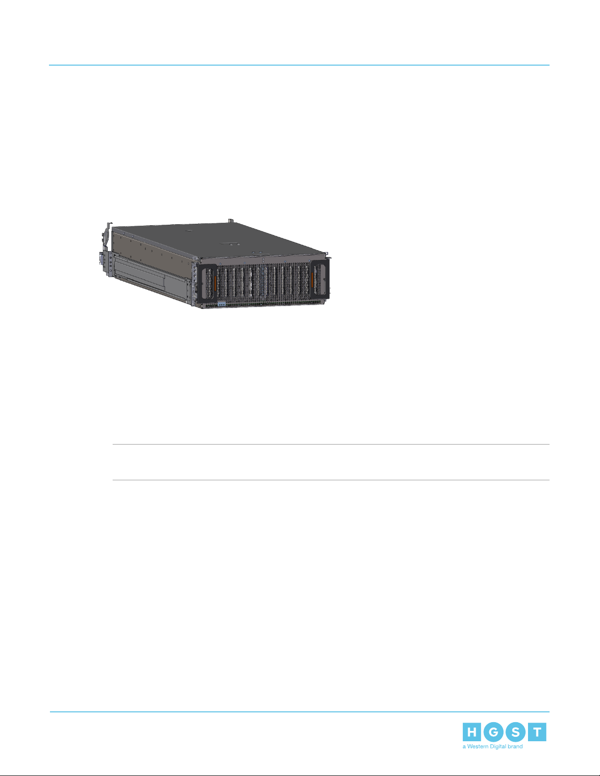
Figure 1: Ultrastar Serv60+8
The Ultrastar®Serv60+8 is a 4U form factor, high density, rack-mounted storage enclosure that is capable
of hosting up to 60 HDD SAS or SATA drives. The maximum data storage capacity of the Ultrastar Serv60+8
is720TB using 12TB HGST Ultrastar®He12HDDs plus an additional 61.44 TB usingHGST Ultrastar®SS300
SSDs in the system SSD slots. (For a full list of compatible drives and total storage capacities, see the List
of Compatible Drives on page 13.) The Ultrastar Serv60+8 also integrates an Intel Skylake based server
front end. The serverisbuiltaround an Intel Sawtooth Pass S2600ST motherboard and supports 2 LGA3647-0
(Socket P) processor sockets CPUs, 16 (8 per CPU) slots of DDR4 ECC DIMM memory, and leverages an
AST2500 BMC for out-of-band management of the server subsystem.The enclosure runs on an input voltage
of 200 - 240 VACandconsumes~1800Wofpowerundertypical conditions. It requires a maximum of ~2000W
at full load.
Note: Max and Typical Power Consumption values represent the output power to the system. Input
power will vary depending on the PSU efficiency and load sharing between PSUs
The system contains three externally facing Half-Height, Half-Length (HHHL) PCIe x16 slots, and 3 externally
facing HHHL PCIe x8 slots.
It is designed to fit within a 4U rack space and requires 1200 mm (47.24in.) of usable rack space, frame to
frame. A fully loaded system will add 95.25 kg / 210 lbs. of static load when fully loaded with drives.
• 4U Storage Server
• Supports up to 60 HDD Drives
• Can support 3.5” drives and 2.5” SSD drives (2.5" requires an adapter) in the 60 available drive bays.
Supports an additional 8 2.5" drives in the system SSD slots located in the center channel
• Up to 12W per drive slot for the 60 HDD data storage drives (Cannot exceed 85A on the 5V rail) and 25W
per slot for the 8 system SSD slots
• House and control six (6) N+1 redundant 80mm fans
• Powered by two (2) redundant 2000W PSUs
• Toolless replacement of all Customer Replaceable Units (CRUs)
• Fits within a standard EIA-310 rack including all necessary cable management
• Supports Highline Input Power
6
Page 7
1 Overview
Installation Guide 1.2 Ultrastar Serv60+8 Layout
• Dual Skylake LGA3647 Socket Processors
• 16 DDR4 ECC DIMM slots
• ASPEED AST2500 BMC
• Lewisburg PCH C624 Chipset
1.2 Ultrastar Serv60+8 Layout
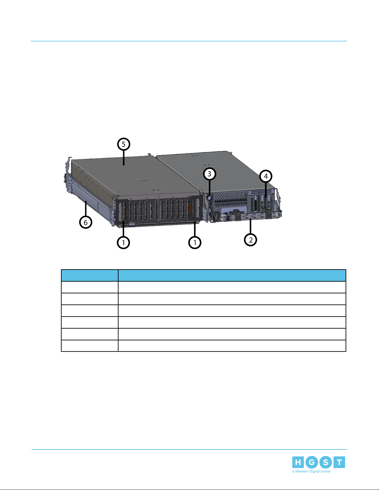
Figure 2: Front and Rear Product Layout
Table 1: Front and Rear Component Identification
ComponentNumber
Enclosure Handles1
CMA2
PSUs3
Rear IO Ports4
Chassis Cover5
Rails6
7
Page 8
1 Overview
Installation Guide 1.2 Ultrastar Serv60+8 Layout
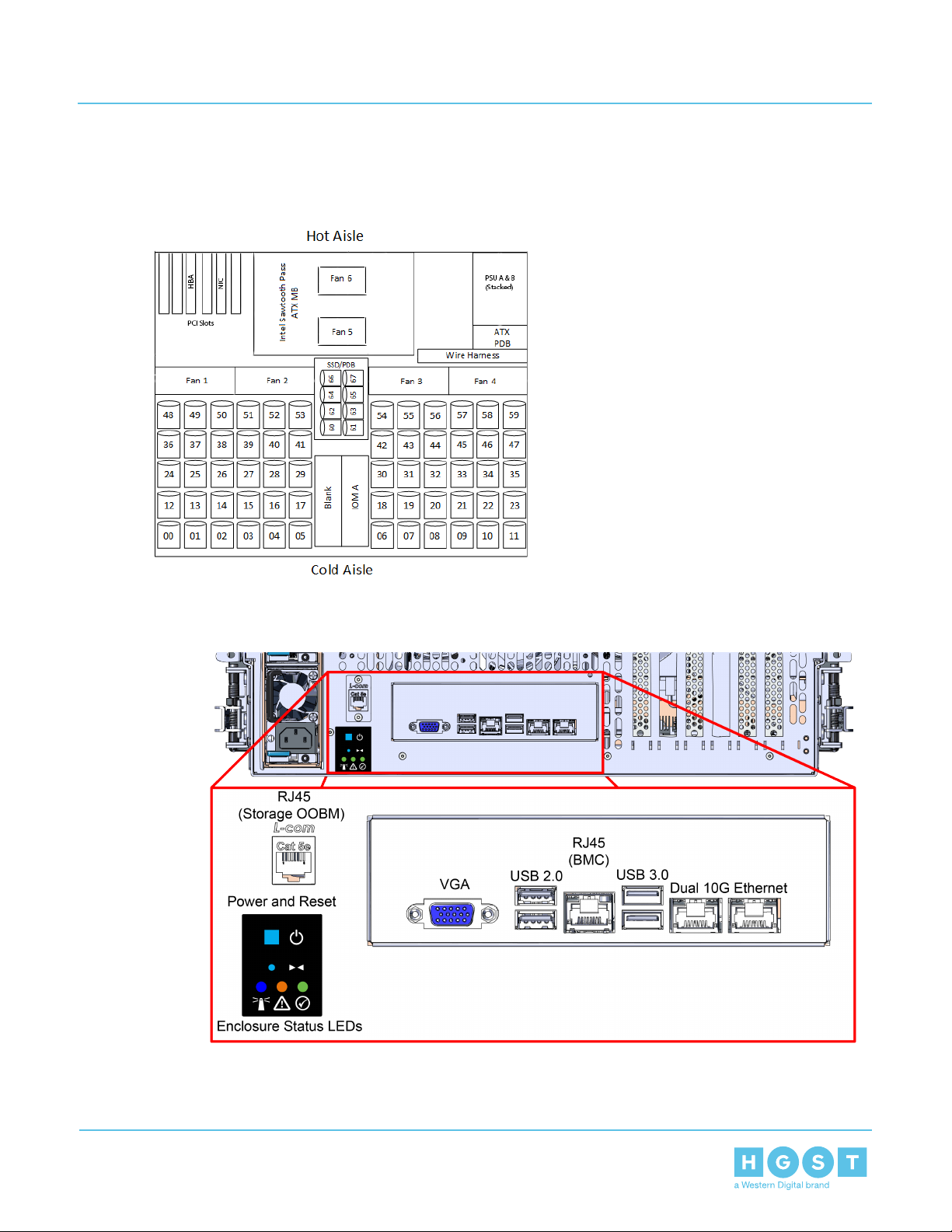
The following is an image of the layout of the major system components inside the Ultrastar Serv60+8.
Figure 3: Component Layout
Figure 4: Rear IO Ports
8
Page 9
1 Overview
Installation Guide 1.3 Ultrastar Serv60+8 Specification Summary
1.3 Ultrastar Serv60+8 Specification Summary
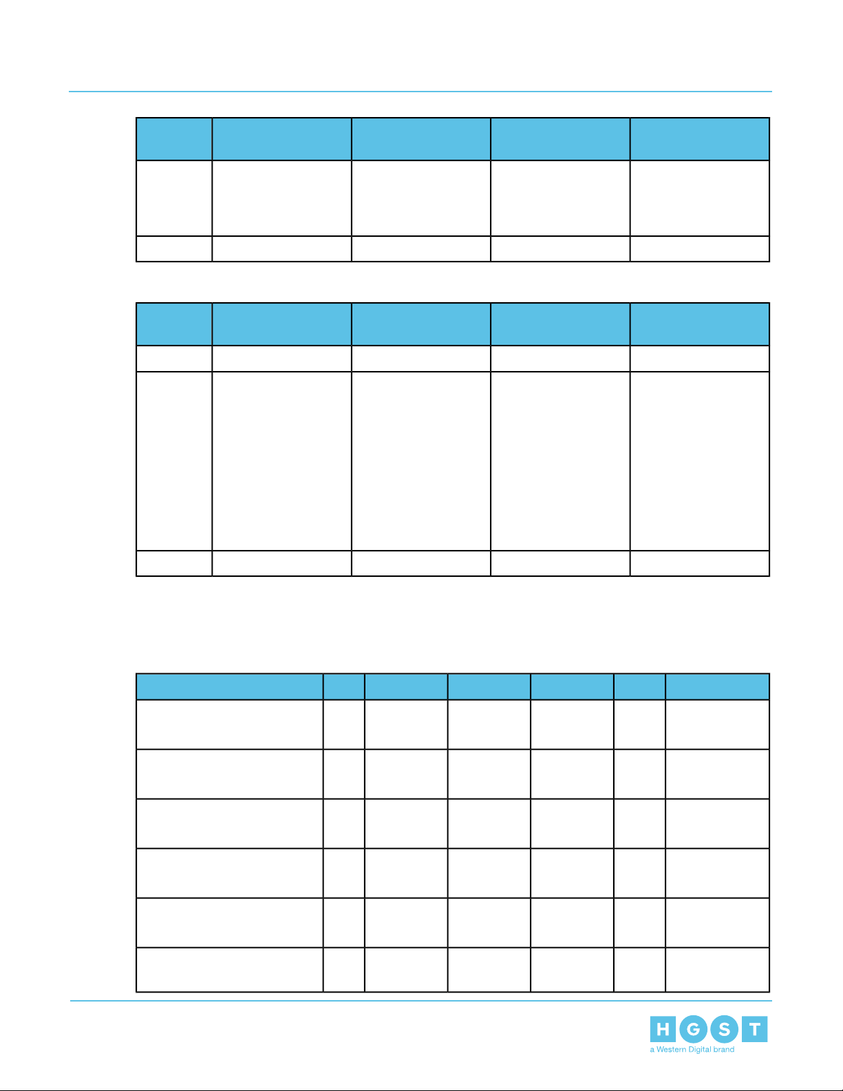
Table 2: Environmental Specification Summary
OperationalNon-OperationalSpecication
5°C to 35°C-40°C to 70°CTemperature
20°C per hour maximum30°C per hour maximumTemperature Gradient
1°C per 300m above 900m1°C per 300m above 3000mTemperature De-rating
8-90% Non-Condensing8-90% Non-CondensingRelative Humidity
30% per hour maximum30% per hour maximumRelative Humidity Gradient
-300m to 3048m / -984 ft. to 10,000 ft.-300m to 12,000m / -984 ft. to 39,370 ftAltitude
Table 3: Electrical Specifications
ValueSpecication
~2000WMax Power Consumption
~1800WTypical Power Consumption
Note: Max and Typical Power Consumption
values represent the output power to the
system. Input power will vary depending on
thePSU efficiency and load sharing between
PSUs
200 - 240 VACInput Voltage
C14PSU Connector Type
80 PLUS PlatinumPSU Efciency
Inrush Current Maximum (per PSU)
Caution: The Ultrastar Serv60+8 can only be plugged into highline. If the unit is plugged into lowline,
the PSU will report a "Critical" state whenstatus pages are queried using SES.In this case, the enclosure
will power up, but the drives will not.
AC line inrush current shall not exceed 35A peak
measured per IPC-9592B(L) Appendix C-4.1.
15ATypical Inrush Current (per PSU)
Table 4: Mechanical Specifications
Shock
10G, 0 - peak,11ms half sine; 3
positive and 3 negative pulses in each
axis shock
9
OperationalNon-OperationalSpecication
5G, 0 - peak, 11ms half sine; 3
positive and 3 negative pulses in each
axis- minimum 6 seconds between
Page 10
1 Overview
Installation Guide 1.4 Ultrastar Serv60+8 Rack Requirements
OperationalNon-OperationalSpecication
shocks to allow for write/read
recovery
Vibration
Dimensions with CMA
Required Rack Width
Table 5: Performance Specifications
0.75G, 0 - peak swept sine; 5 -500Hz;
1 complete sweep @ 1/2 octave per
minute
95.25 kg / 210 lbs.Weight
W: 447mm x L: 1197 mm x H: 175mm / W: 17.6in. x L: 47.13in.. x H:
6.89in.
1026 mm / 40.39in.Length without CMA
450mm with (17.72in.) with 465mm (18.31in.) ± 1.5mm nominal hole
spacing. See EIA-310 Rack Standard
1200 mm (47.24in.) of usable rack space, frame to frameRequired Rack Depth
4URack Units (U)
32 in. - 36 in.Vertical Rack Rail Spacing
0.10G,0 - peak swept sine; 5 -500Hz;
1 complete sweep @ 1/2octave per
minute
ValueSpecication
Intel Sawtooth Pass S2600STMother Board
Intel SkylakeProcessor Type
LGA3647-0 (Socket P) processor socketsSocket
2Number of Processors
Lewisburg PCH C624 ChipsetChipset
DDR4 ECC DIMMMemory Type
16 (8 per CPU)Number of Memory Slots
IntegratedGraphics
AST2500Sever BMC Chip
60 HDD / 8 SSDNumber of Drive Slots
12Gbps SAS / 6Gbps SATAData Transfer Rates
Max Raw Data Storage Capacity
720TB using 12TB HGST Ultrastar®He12 HDDs / 61.44
TB using HGST Ultrastar®SS300 SSDs
1.4 Ultrastar Serv60+8 Rack Requirements
The Ultrastar Serv60+8 is designed to be installed into a rack that meets the EIA-310 standard at a minimum
1200 mm (47.24in.) of usable rack space, frame to frame. The vertical rack rails must be set between 32 in.
10
Page 11
1 Overview
Installation Guide 1.4 Ultrastar Serv60+8 Rack Requirements
- 36 in. to support the enclosure. It requires 4U of rack space, and it should be installed into the rack at the
lowest possible U height to keep the load on the rack balanced.
Table 6: Required Rack Specifications
RequirementParameter
Rack Depth
Rack Width
Warning: When extended out of the rack on the rail system, the Ultrastar Serv60+8 will
be ~950 mm / 37.4in. extended outward. This is a tipping hazard. Make sure that any rack supporting
the enclosure MUST BE BOLTED TO THE FLOOR before servicing or extending out of the rack.
Ensure that leveling feet, anti-tilt, and any other safety features recommended by the specific rack
manufacturers have also been deployed before servicing.
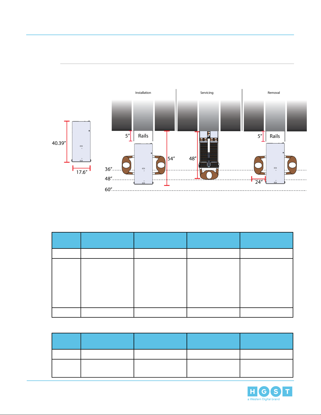
The following section provides specific information necessary to install, service, and remove the Ultrastar
Serv60+8. The installation of the Ultrastar Serv60+8 requires two people and a space of 1371mm / 54in. in
front of the installation space.The servicing of the enclosure requires one person and a minimum of 1219.2mm
/ 48in. of space in front of the installation space. The removal of the enclosure requires two people, 1371mm
/ 54in. of space in front of the installation space, and 24in. on either side of the enclosure for two people to
remove the enclosure.
1200 mm (47.24in.) of usable rack space, frame to
frame
450mm with (17.72in.) with 465mm (18.31in.) ±
1.5mm nominal hole spacing. See EIA-310 Rack
Standard
4URack Units (U)
32 in. - 36 in.Vertical Rack Rail Spacing
2250 lbs.Static Load Rating
1360.77 / 3000 lbs.Dynamic Load Rating
Warning: The handles on the front of the chassis are not intended to be used to support the weight of
the Ultrastar Serv60+8. Lifting the unit by the chassis handles or trying to support the unit on thehandles
can cause them to fail. This can cause serious damage to the unit or serious bodily harm to those
11
Page 12
1 Overview
Installation Guide 1.4 Ultrastar Serv60+8 Rack Requirements
handling the unit. Always team lift the chassis by gripping the underside of the unit, and nevertry to lift
a chassis that is filled with drives.
Figure 5: Installation, Servicing, and Removal
1.4.1 Compatible Hardware Configuration
The following table(s) list the approved hardware configurations for the Ultrastar Serv60+8:
Table 7: Compatible Hardware Configuration 1
PDU (Vertical)RackParameter
Part
Number
Table 8: Compatible Hardware Configuration 2
AS-160099-03
(Drawing Number
EMCOR 526121 Rev
5)
412-0761-11_STV -4501
412-0761-20_STV -4502
412-0761-23_STV -4503
PDU (Vertical)RackParameter
PDU Mounting
Bracket
KIT-MBVPT-1B (one
kit per PDU)
PDU Mounting
Bracket
AdditionalMounting
Bracket Hardware
VariousServer TechnologyServer TechnologyCRENLO/EMCORVendor
4 x M6 x 16 Hex Cap
Screws
8 x M6 Fender
Washers
4 x M6 Hex Nut with
Nylon Lock
Varies221Quantity
AdditoinalMounting
Bracket Hardware
VariousServer TechnologyServer TechnologyAFCO/LegrandVendor
Part
Number
42RU – WEDIT605
NoneKIT-MB-40412-0761-11_STV -4501Options:
412-0761-20_STV -4502
12
Page 13
1 Overview
Installation Guide 1.5 List of Compatible Drives
PDU (Vertical)RackParameter
45RU – WEDIT604 412-0761-23_STV-4503
48RU – WEDIT603
51RU – WEDIT606
Table 9: Compatible Hardware Configuration 3
PDU (Vertical)RackParameter
Part
Number
SR42UBDP (Rack)
SREXTENDER 25U
(Rack Extension)
SREXTENDER 42U
(Rack Extension)
SREXTENDER 48U
(Rack Extension)
412-0761-20_STV -4502
412-0761-23_STV -4503
PDU Mounting
Bracket
PDU Mounting
Bracket
AdditoinalMounting
Bracket Hardware
N/A121 rackQuantity
AdditoinalMounting
Bracket Hardware
VariousServer TechnologyServer TechnologyTRIPP LITEVendor
NoneKIT-MBVPT-1B412-0761-11_STV -4501Options:
1.5 List of Compatible Drives
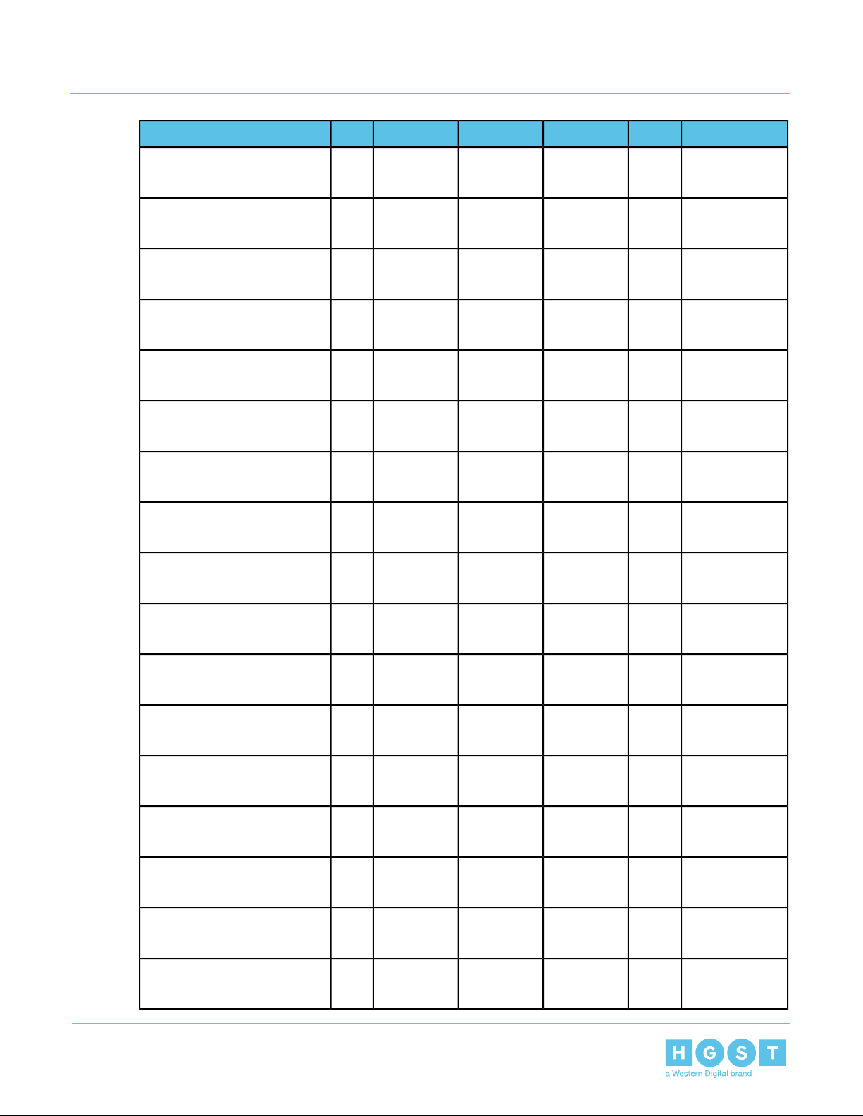
Table 10: HDDs
w/ 3.5 in. drive carrier
w/ 3.5 in. drive carrier
w/ 3.5 in. drive carrier
w/ 3.5 in. drive carrier
w/ 3.5 in. drive carrier
w/ 3.5 in. drive carrier
N/A121 rackQuantity
Part NumberV olumeEncryptionSector SizeInterfaceTypeDrive
1EX11836TBSE4KnSAS 12Gb/sHDDHGST Ultrastar®DC HC310
1EX11826TBTCG4KnSAS12Gb/sHDDHGST Ultrastar®DC HC310
1EX11856TBSE512eSAS12Gb/sHDDHGST Ultrastar®DC HC310
1EX11846TBTCG512eSAS12Gb/sHDDHGST Ultrastar®DC HC310
1EX11876TBSE4KnSATA 6Gb/sHDDHGST Ultrastar®DC HC310
1EX11866TBTCG4KnSATA 6Gb/sHDDHGST Ultrastar®DC HC310
13
Page 14
1 Overview
Installation Guide 1.5 List of Compatible Drives
Part NumberV olumeEncryptionSector SizeInterfaceTypeDrive
1EX11896TBSE512eSATA 6Gb/sHDDHGST Ultrastar®DC HC310
w/ 3.5 in. drive carrier
1EX11886TBTCG512eSATA 6Gb/sHDDHGST Ultrastar®DC HC310
w/ 3.5 in. drive carrier
1EX12218TBSE4KnSAS 12Gb/sHDDHGST Ultrastar®DC HC320
w/ 3.5 in. drive carrier
1EX12208TBTCG4KnSAS12Gb/sHDDHGST Ultrastar®DC HC320
w/ 3.5 in. drive carrier
1EX13428TBTCG-FIPS4KnSAS12Gb/sHDDHGST Ultrastar®DC HC320
w/ 3.5 in. drive carrier
1EX12238TBSE512eSAS12Gb/sHDDHGST Ultrastar®DC HC320
w/ 3.5 in. drive carrier
w/ 3.5 in. drive carrier
w/ 3.5 in. drive carrier
w/ 3.5 in. drive carrier
w/ 3.5 in. drive carrier
w/ 3.5 in. drive carrier
w/ 3.5 in. drive carrier
w/ 3.5 in. drive carrier
w/ 3.5 in. drive carrier
w/ 3.5 in. drive carrier
1EX12228TBTCG512eSAS12Gb/sHDDHGST Ultrastar®DC HC320
1EX13438TBTCG-FIPS512eSAS 12Gb/sHDDHGST Ultrastar®DC HC320
1EX12258TBSE4KnSATA 6Gb/sHDDHGST Ultrastar®DC HC320
1EX12248TBTCG4KnSATA 6Gb/sHDDHGST Ultrastar®DC HC320
1EX12278TBSE512eSATA 6Gb/sHDDHGST Ultrastar®DC HC320
1EX12268TBSED512eSATA 6Gb/sHDDHGST Ultrastar®DC HC320
1EX048210TBISE4KnSAS12Gb/sHDDHGST Ultrastar®He10
1EX048410TBSE4KnSAS 12Gb/sHDDHGST Ultrastar®He10
1EX048310TBTCG4KnSAS 12Gb/sHDDHGST Ultrastar®He10
w/ 3.5 in. drive carrier
w/ 3.5 in. drive carrier
1EX134010TBTCG-FIPS4KnSAS 12Gb/sHDDHGST Ultrastar®He10
1EX048510TBISE512eSAS12Gb/sHDDHGST Ultrastar®He10
14
Page 15

1 Overview
Installation Guide 1.5 List of Compatible Drives
Part NumberV olumeEncryptionSector SizeInterfaceTypeDrive
1EX048710TBSE512eSAS 12Gb/sHDDHGST Ultrastar®He10
w/ 3.5 in. drive carrier
1EX048610TBTCG512eSAS12Gb/sHDDHGST Ultrastar®He10
w/ 3.5 in. drive carrier
1EX134110TBTCG-FIPS512eSAS12Gb/sHDDHGST Ultrastar®He10
w/ 3.5 in. drive carrier
1EX049410TBISE4KnSATA 6Gb/sHDDHGST Ultrastar®He10
w/ 3.5 in. drive carrier
1EX049610TBSE4KnSATA 6Gb/sHDDHGST Ultrastar®He10
w/ 3.5 in. drive carrier
1EX049510TBSED4KnSATA 6Gb/sHDDHGST Ultrastar®He10
w/ 3.5 in. drive carrier
w/ 3.5 in. drive carrier
w/ 3.5 in. drive carrier
w/ 3.5 in. drive carrier
w/ 3.5 in. drive carrier
w/ 3.5 in. drive carrier
w/ 3.5 in. drive carrier
w/ 3.5 in. drive carrier
w/ 3.5 in. drive carrier
w/ 3.5 in. drive carrier
1EX049710TBISE512eSATA 6Gb/sHDDHGST Ultrastar®He10
1EX049910TBSE512eSATA 6Gb/sHDDHGST Ultrastar®He10
1EX049810TBSED512eSATA 6Gb/sHDDHGST Ultrastar®He10
1EX100412TBISE4KnSAS12Gb/sHDDHGST Ultrastar®He12
1EX100612TBSE4KnSAS 12Gb/sHDDHGST Ultrastar®He12
1EX100512TBTCG4KnSAS 12Gb/sHDDHGST Ultrastar®He12
1EX133912TBTCG-FIPS4KnSAS 12Gb/sHDDHGST Ultrastar®He12
1EX100712TBISE512eSAS12Gb/sHDDHGST Ultrastar®He12
1EX100912TBSE512eSAS 12Gb/sHDDHGST Ultrastar®He12
w/ 3.5 in. drive carrier
w/ 3.5 in. drive carrier
1EX100812TBTCG512eSAS12Gb/sHDDHGST Ultrastar®He12
1EX133812TBTCG-FIPS512eSAS12Gb/sHDDHGST Ultrastar®He12
15
Page 16
1 Overview
Installation Guide 1.5 List of Compatible Drives
Part NumberV olumeEncryptionSector SizeInterfaceTypeDrive
1EX101012TBISE4KnSATA 6Gb/sHDDHGST Ultrastar®He12
w/ 3.5 in. drive carrier
1EX101212TBSE4KnSATA 6Gb/sHDDHGST Ultrastar®He12
w/ 3.5 in. drive carrier
1EX101112TBSED4KnSATA 6Gb/sHDDHGST Ultrastar®He12
w/ 3.5 in. drive carrier
1EX101312TBISE512eSATA 6Gb/sHDDHGST Ultrastar®He12
w/ 3.5 in. drive carrier
1EX101512TBSE512eSATA 6Gb/sHDDHGST Ultrastar®He12
w/ 3.5 in. drive carrier
1EX101412TBSED512eSATA 6Gb/sHDDHGST Ultrastar®He12
w/ 3.5 in. drive carrier
w/ 3.5 in. drive carrier
w/ 3.5 in. drive carrier
w/ 3.5 in. drive carrier
w/ 3.5 in. drive carrier
w/ 3.5 in. drive carrier
w/ 3.5 in. drive carrier
Table 11: SSDs w/ 2.5 in. drive carrier
w/ 2.5 in. drive carrier
1EX178814TBSE4KnSAS 12Gb/sHDDHGST Ultrastar®HC530
1EX178914TBTCG4KnSAS 12Gb/sHDDHGST Ultrastar®HC530
1EX179114TBSE512eSAS 12Gb/sHDDHGST Ultrastar®HC530
1EX179214TBTCG512eSAS12Gb/sHDDHGST Ultrastar®HC530
1EX179014TBSE4KnSATA 6Gb/sHDDHGST Ultrastar®HC530
1EX179314TBSE512eSATA 6Gb/sHDDHGST Ultrastar®HC530
InterfaceTypeDrive
Writes
V olumeEncryptionDrive
Part
Number
1EX1276400GBISERI-3DW/DSAS 12Gb/sSSDHGST Ultrastar®SS200
w/ 2.5 in. drive carrier
w/ 2.5 in. drive carrier
1EX1278400GBSERI-3DW/DSAS 12Gb/sSSDHGST Ultrastar®SS200
1EX1353400GBTCGRI-3DW/DSAS 12Gb/sSSDHGST Ultrastar®SS200
16
Page 17

1 Overview
Installation Guide 1.5 List of Compatible Drives
w/ 2.5 in. drive carrier
w/ 2.5 in. drive carrier
w/ 2.5 in. drive carrier
w/ 2.5 in. drive carrier
w/ 2.5 in. drive carrier
w/ 2.5 in. drive carrier
w/ 2.5 in. drive carrier
w/ 2.5 in. drive carrier
InterfaceTypeDrive
Writes
V olumeEncryptionDrive
Part
Number
1EX1273400GBISEME-10DW/DSAS 12Gb/sSSDHGST Ultrastar®SS300
1EX1159400GBSEME-10DW/DSAS 12Gb/sSSDHGST Ultrastar®SS300
1EX1346400GBTCGME-10DW/DSAS 12Gb/sSSDHGST Ultrastar®SS300
1EX1347400GBTCG-FIPSME-10DW/DSAS 12Gb/sSSDHGST Ultrastar®SS300
1EX1282400GBISERI-3DW/DSAS 12Gb/sSSDHGST Ultrastar®SS300
1EX1284400GBSERI-3DW/DSAS 12Gb/sSSDHGST Ultrastar®SS300
1EX1350400GBTCGRI-3DW/DSAS 12Gb/sSSDHGST Ultrastar®SS300
1EX1351400GBTCG-FIPSRI-3DW/DSAS 12Gb/sSSDHGST Ultrastar®SS300
w/ 2.5 in. drive carrier
w/ 2.5 in. drive carrier
w/ 2.5 in. drive carrier
w/ 2.5 in. drive carrier
w/ 2.5 in. drive carrier
w/ 2.5 in. drive carrier
w/ 2.5 in. drive carrier
w/ 2.5 in. drive carrier
w/ 2.5 in. drive carrier
1EX1279400GBSERI-1.8DW/DSATA 6Gb/sSSDSandisk®Cloudspeed Ultra Gen. II
1EX1275800GBISERI-3DW/DSAS 12Gb/sSSDHGST Ultrastar®SS200
1EX1277800GBSERI-3DW/DSAS 12Gb/sSSDHGST Ultrastar®SS200
1EX1352800GBTCGRI-3DW/DSAS 12Gb/sSSDHGST Ultrastar®SS200
1EX1272800GBISEME-10DW/DSAS 12Gb/sSSDHGST Ultrastar®SS300
1EX1274800GBSEME-10DW/DSAS 12Gb/sSSDHGST Ultrastar®SS300
1EX1344800GBTCGME-10DW/DSAS 12Gb/sSSDHGST Ultrastar®SS300
1EX1345800GBTCG-FIPSME-10DW/DSAS 12Gb/sSSDHGST Ultrastar®SS300
1EX1281800GBISERI-3DW/DSAS 12Gb/sSSDHGST Ultrastar®SS300
17
Page 18

1 Overview
Installation Guide 1.5 List of Compatible Drives
InterfaceTypeDrive
w/ 2.5 in. drive carrier
w/ 2.5 in. drive carrier
w/ 2.5 in. drive carrier
w/ 2.5 in. drive carrier
w/ 2.5 in. drive carrier
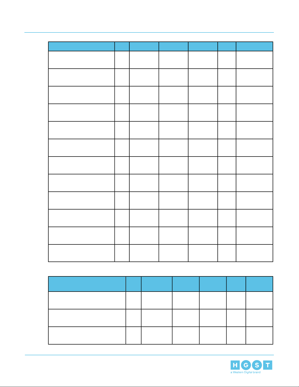
Table 12: SSDs w/ 3.5 in to 2.5 in drive carrier
InterfaceTypeDrive
w/ 3.5 in to 2.5 in drive carrier
Writes
Writes
V olumeEncryptionDrive
V olumeEncryptionDrive
Part
Number
1EX1283800GBSERI-3DW/DSAS 12Gb/sSSDHGST Ultrastar®SS300
1EX1348800GBTCGRI-3DW/DSAS 12Gb/sSSDHGST Ultrastar®SS300
1EX1349800GBTCG-FIPSRI-3DW/DSAS 12Gb/sSSDHGST Ultrastar®SS300
1EX1280800GBSERI-1.8DW/DSATA 6Gb/sSSDSandisk®Cloudspeed Ultra Gen. II
1EX17821.6TBTCG-FIPSRI-3DW/DSAS 12Gb/sSSDHGST Ultrastar®SS200
Part
Number
1EX1291400GBISERI-3DW/DSAS 12Gb/sSSDHGST Ultrastar®SS200
w/ 3.5 in to 2.5 in drive carrier
w/ 3.5 in to 2.5 in drive carrier
w/ 3.5 in to 2.5 in drive carrier
w/ 3.5 in to 2.5 in drive carrier
w/ 3.5 in to 2.5 in drive carrier
w/ 3.5 in to 2.5 in drive carrier
w/ 3.5 in to 2.5 in drive carrier
w/ 3.5 in to 2.5 in drive carrier
w/ 3.5 in to 2.5 in drive carrier
1EX1293400GBSERI-3DW/DSAS 12Gb/sSSDHGST Ultrastar®SS200
1EX1315400GBTCGRI-3DW/DSAS 12Gb/sSSDHGST Ultrastar®SS200
1EX1287400GBISEME-10DW/DSAS 12Gb/sSSDHGST Ultrastar®SS300
1EX1289400GBSEME-10DW/DSAS 12Gb/sSSDHGST Ultrastar®SS300
1EX1312400GBTCGME-10DW/DSAS 12Gb/sSSDHGST Ultrastar®SS300
1EX1479400GBTCG-FIPSME-10DW/DSAS 12Gb/sSSDHGST Ultrastar®SS300
1EX1296400GBISERI-3DW/DSAS 12Gb/sSSDHGST Ultrastar®SS300
1EX1298400GBSERI-3DW/DSAS 12Gb/sSSDHGST Ultrastar®SS300
1EX1309400GBTCGRI-3DW/DSAS 12Gb/sSSDHGST Ultrastar®SS300
18
Page 19

1 Overview
Installation Guide 1.5 List of Compatible Drives
w/ 3.5 in to 2.5 in drive carrier
w/ 3.5 in to 2.5 in drive carrier
w/ 3.5 in to 2.5 in drive carrier
w/ 3.5 in to 2.5 in drive carrier
w/ 3.5 in to 2.5 in drive carrier
w/ 3.5 in to 2.5 in drive carrier
w/ 3.5 in to 2.5 in drive carrier
w/ 3.5 in to 2.5 in drive carrier
InterfaceTypeDrive
Writes
V olumeEncryptionDrive
Part
Number
1EX1481400GBTCG-FIPSRI-3DW/DSAS 12Gb/sSSDHGST Ultrastar®SS300
1EX1294400GBSERI-1.8DW/DSATA 6Gb/sSSDSandisk®Cloudspeed Ultra Gen. II
1EX1318480GBTCGRI-1DW/DSAS 12Gb/sSSDHGST Ultrastar®SS200
1EX1290800GBISERI-3DW/DSAS 12Gb/sSSDHGST Ultrastar®SS200
1EX1292800GBSERI-3DW/DSAS 12Gb/sSSDHGST Ultrastar®SS200
1EX1314800GBTCGRI-3DW/DSAS 12Gb/sSSDHGST Ultrastar®SS200
1EX1295800GBISERI-3DW/DSAS 12Gb/sSSDHGST Ultrastar®SS300
1EX1297800GBSERI-3DW/DSAS 12Gb/sSSDHGST Ultrastar®SS300
w/ 3.5 in to 2.5 in drive carrier
w/ 3.5 in to 2.5 in drive carrier
w/ 3.5 in to 2.5 in drive carrier
w/ 3.5 in to 2.5 in drive carrier
w/ 3.5 in to 2.5 in drive carrier
w/ 3.5 in to 2.5 in drive carrier
w/ 3.5 in to 2.5 in drive carrier
w/ 3.5 in to 2.5 in drive carrier
w/ 3.5 in to 2.5 in drive carrier
1EX1308800GBTCGRI-3DW/DSAS 12Gb/sSSDHGST Ultrastar®SS300
1EX1480800GBTCG-FIPSRI-3DW/DSAS 12Gb/sSSDHGST Ultrastar®SS300
1EX1286800GBISEME-10DW/DSAS 12Gb/sSSDHGST Ultrastar®SS300
1EX1288800GBSEME-10DW/DSAS 12Gb/sSSDHGST Ultrastar®SS300
1EX1311800GBTCGME-10DW/DSAS 12Gb/sSSDHGST Ultrastar®SS300
1EX1478800GBTCG-FIPSME-10DW/DSAS 12Gb/sSSDHGST Ultrastar®SS300
1EX1305800GBSERI-1.8DW/DSATA 6Gb/sSSDSandisk®Cloudspeed Ultra Gen. II
1EX1317960GBTCGRI-1DW/DSAS 12Gb/sSSDHGST Ultrastar®SS200
1EX13031.6TBISERI-3DW/DSAS 12Gb/sSSDHGST Ultrastar®SS200
19
Page 20

1 Overview
Installation Guide 1.5 List of Compatible Drives
w/ 3.5 in to 2.5 in drive carrier
w/ 3.5 in to 2.5 in drive carrier
w/ 3.5 in to 2.5 in drive carrier
w/ 3.5 in to 2.5 in drive carrier
w/ 3.5 in to 2.5 in drive carrier
w/ 3.5 in to 2.5 in drive carrier
w/ 3.5 in to 2.5 in drive carrier
w/ 3.5 in to 2.5 in drive carrier
InterfaceTypeDrive
Writes
V olumeEncryptionDrive
Part
Number
1EX17831.6TBISERI-3DW/DSAS 12Gb/sSSDHGST Ultrastar®SS200
1EX13041.6TBSERI-3DW/DSAS 12Gb/sSSDHGST Ultrastar®SS200
1EX17841.6TBSERI-3DW/DSAS 12Gb/sSSDHGST Ultrastar®SS200
1EX13131.6TBTCGRI-3DW/DSAS 12Gb/sSSDHGST Ultrastar®SS200
1EX17851.6TBTCGRI-3DW/DSAS 12Gb/sSSDHGST Ultrastar®SS200
1EX12991.6TBISERI-3DW/DSAS 12Gb/sSSDHGST Ultrastar®SS300
1EX17791.6TBISERI-3DW/DSAS 12Gb/sSSDHGST Ultrastar®SS300
1EX17681.6TBISEME-10DW/DSAS 12Gb/sSSDHGST Ultrastar®SS300
w/ 3.5 in to 2.5 in drive carrier
w/ 3.5 in to 2.5 in drive carrier
w/ 3.5 in to 2.5 in drive carrier
w/ 3.5 in to 2.5 in drive carrier
w/ 3.5 in to 2.5 in drive carrier
w/ 3.5 in to 2.5 in drive carrier
w/ 3.5 in to 2.5 in drive carrier
w/ 3.5 in to 2.5 in drive carrier
w/ 3.5 in to 2.5 in drive carrier
1EX13001.6TBSERI-3DW/DSAS 12Gb/sSSDHGST Ultrastar®SS300
1EX17801.6TBSERI-3DW/DSAS 12Gb/sSSDHGST Ultrastar®SS300
1EX17761.6TBSEME-10DW/DSAS 12Gb/sSSDHGST Ultrastar®SS300
1EX13071.6TBTCGRI-3DW/DSAS 12Gb/sSSDHGST Ultrastar®SS300
1EX17811.6TBTCGRI-3DW/DSAS 12Gb/sSSDHGST Ultrastar®SS300
1EX17771.6TBTCGME-10DW/DSAS 12Gb/sSSDHGST Ultrastar®SS300
1EX17871.6TBTCG-FIPSRI-3DW/DSAS 12Gb/sSSDHGST Ultrastar®SS300
1EX17821.6TBTCG-FIPSRI-3DW/DSAS 12Gb/sSSDHGST Ultrastar®SS300
1EX13011.6TBISERI-10DW/DSAS 12Gb/sSSDHGST Ultrastar®SS300
20
Page 21

1 Overview
Installation Guide 1.5 List of Compatible Drives
w/ 3.5 in to 2.5 in drive carrier
w/ 3.5 in to 2.5 in drive carrier
w/ 3.5 in to 2.5 in drive carrier
w/ 3.5 in to 2.5 in drive carrier
w/ 3.5 in to 2.5 in drive carrier
w/ 3.5 in to 2.5 in drive carrier
w/ 3.5 in to 2.5 in drive carrier
w/ 3.5 in to 2.5 in drive carrier
InterfaceTypeDrive
Writes
V olumeEncryptionDrive
Part
Number
1EX13021.6TBSERI-10DW/DSAS 12Gb/sSSDHGST Ultrastar®SS300
1EX13101.6TBTCGRI-10DW/DSAS 12Gb/sSSDHGST Ultrastar®SS300
1EX17861.6TBTCG-FIPSME-10DW/DSAS 12Gb/sSSDHGST Ultrastar®SS300
1EX13191.6TBSERI-1.8DW/DSATA 6Gb/sSSDSandisk®Cloudspeed Ultra Gen. II
1EX13161.92TBTCGRI-1DW/DSAS 12Gb/sSSDHGST Ultrastar®SS200
1EX05783.2TBISERI-3DW/DSAS 12Gb/sSSDHGST Ultrastar®SS200
1EX12853.2TBISERI-3DW/DSAS 12Gb/sSSDHGST Ultrastar®SS300
1EX13063.2TBSERI-3DW/DSAS 12Gb/sSSDHGST Ultrastar®SS300
w/ 3.5 in to 2.5 in drive carrier
w/ 3.5 in to 2.5 in drive carrier
Table 13: M.2s
1EX05793.84TBISERI-1DW/DSAS 12Gb/sSSDHGST Ultrastar®SS200
1EX05807.68TBISERI-1DW/DSAS 12Gb/sSSDHGST Ultrastar®SS200
VolumeEncryptionInterfaceFormFactorTypeDrive
Part
Number
1EX1143120GBSEDSATA 6Gb/sM.2 2280SSDHGST Ultrastar®SA210
1EX1569128GBN/ASATA 6Gb/sM.2 2280SSDSanDisk®X600
1EX1574128GBSEDSATA 6Gb/sM.2 2280SSDSanDisk®X600
1EX1354240GBSEDSATA 6Gb/sM.2 2280SSDHGST Ultrastar®SA210
1EX1570256GBN/ASATA 6Gb/sM.2 2280SSDSanDisk®X600
1EX1575256GBSEDSATA 6Gb/sM.2 2280SSDSanDisk®X600
1EX1579480GBSEDSATA 6Gb/sM.2 2280SSDHGST Ultrastar®SA210
1EX1571512GBN/ASATA 6Gb/sM.2 2280SSDSanDisk®X600
1EX1576512GBSEDSATA 6Gb/sM.2 2280SSDSanDisk®X600
21
Page 22

1 Overview
Installation Guide 1.5 List of Compatible Drives
VolumeEncryptionInterfaceFormFactorTypeDrive
Part
Number
1EX1580960GBSEDSATA 6Gb/sM.2 2280SSDHGST Ultrastar®SA210
1EX15721TBN/ASATA 6Gb/sM.2 2280SSDSanDisk®X600
1EX15771TBSEDSATA 6Gb/sM.2 2280SSDSanDisk®X600
1EX15811.92TBSEDSATA 6Gb/sM.2 2280SSDHGST Ultrastar®SA210
1EX15732TBN/ASATA 6Gb/sM.2 2280SSDSanDisk®X600
1EX15782TBSEDSATA 6Gb/sM.2 2280SSDSanDisk®X600
22
Page 23

2 Disclaimers
Installation Guide 2.1 Restricted Access Location
Chapter
2 Disclaimers
2
Learn about the Regulatory, Safety, and Electromagnetic standards for which this product is compliant.
The following chapter describes the Regulatory Statement of Compliance, Safety Compliance, and
Electromagnetic Compatibility Agency Requirements for the Ultrastar Serv60+8.
2.1 Restricted Access Location
The Ultrastar Serv60+8 is intended for installation in a server room or computer room where at least one of
the following conditions apply:
• access can only be gained byservice persons or by users who have been instructed about the restrictions
applied to the location and about any precautions that shall be taken and/or
• access is through the use of a tool or lock and key, or other means of security, and is controlled by the
authority responsible for the location.
2.2 Safety Compliance
Product Name: Ultrastar Serv60+8
Regulatory Model: H4060-S
Electromagnetic Compatibility Emissions: Class A
This product has been tested and evaluated as Information Technology Equipment (ITE) at accredited
third-party laboratories for all safety, emissions and immunity testing required for the countries and regions
where the product is marketed and sold. The product has been verified as compliant with the latest applicable
standards,regulations and directives for those regions/countries. The suitability of this product forotherproduct
categories other than ITE may require further evaluation.
The product is labeled with a unique regulatory model that is printed on the label and affixed to every unit.
The label will provide traceability to the regulatory approvals listed in this document. The document applies
to any product that bears the regulatory model and type names including marketing names other than those
listed in this document.
2.3 Electromagnetic Compatibility (EMC) Class A Compliance
The H4060-S complies with and conforms to the latest international standards as applicable:
Table 14: Emissions and Immunity Compliance Lists
ImmunityEmissions
23
EN 61000-3-2 Harmonic Current EmissionsFCC CFR 47 Part 15, Subpart B
EN 61000-3-3 Voltage Fluctuations and FlickerICES-003
EN 55024EN 55032
KN35CISPR 32
EN 61000-4-2 ESDCE – EMC Directive 2014/30/EU
Page 24

2 Disclaimers
Installation Guide 2.4 Country Certifications
ImmunityEmissions
EN 61000-4-3 Radiated ImmunityVCCI V-3
EN 61000-4-4 EFTBSMI CNS13438
EN 61000-4-5 SurgeKN32
EN 61000-4-6 RF Common ModeAS/NZS CISPR 32
EN 61000-4-8 Power Frequency Magnetic FieldTR CU 020/2011
EN 61000-4-11 Voltage Dips and Interruptions
2.4 Country Certifications
Table 15: Country Certifications
Authority or MarkCountry/Region
NemkoNorth America (Canada, USA)
CEEuropean Union
VCCIJapan
MSIPKorea
BSMITaiwan
RCMAustralia/New Zealand
CU EACRussia, Kazakhstan, Belarus, Armenia
UkrseproUkraine
NOMMexico
SIIIsrael
SABSSouth Africa
BISIndia
24
Page 25

3 Safety
Installation Guide 3.1 Electrostatic Discharge
Chapter
3 Safety
3
The following chapter provides safety and regulatory information for the Ultrastar Serv60+8.
3.1 Electrostatic Discharge
CAUTION
Electrostatic discharge can harm delicate components inside HGST products.
Electrostatic discharge (ESD) is a discharge of stored static electricity that can damage equipment and impair
electrical circuitry. It occurs when electronic components are improperly handled and can result in complete
or intermittent failures.
Wear an ESD wrist strap for installation, service and maintenance to prevent damage to components in the
product. Ensure the antistatic wrist strap is attached to a chassis ground (any unpainted metal surface). If
possible, keep one hand on the frame when you install or remove an ESD-sensitive part.
Before moving ESD-sensitive parts place them in ESD static-protective bags until you are ready to install the
part.
3.2 Optimizing Location
Failuretorecognizethe importance of optimally locating your product and failureto protect against electrostatic
discharge (ESD) when handling your product can result in lowered system performance or system failure.
Do not position the unit in an environment that has extreme high temperatures or extreme low temperatures.
Be aware of the proximity of the unit to heaters, radiators, and air conditioners.
Position the unit so that there is adequate space around it for proper cooling and ventilation. Consult the
product documentation for spacing information.
Keep the unit away from direct strong magnetic fields, excessive dust, and electronic/electrical equipment
that generate electrical noise.
3.3 Power Connections
Be aware of the ampere limit on any power supply or extension cables being used. The total ampere rating
being pulled on a circuit by all devices combined should not exceed 80% of the maximum limit for the circuit.
CAUTION The power outlet must be easily accessible close to the unit.
Always use properly grounded, unmodified electrical outlets and cables. Ensure all outlets and
cables are rated to supply the proper voltage and current.
This unit has more than one power supply connection; both power cords must be removed from the
power supplies to completely remove power from the unit. There is no switch or other disconnect device.
25
Page 26

3 Safety
Installation Guide 3.4 Power Cords
3.4 Power Cords
Use only tested and approved power cords to connect to properly grounded power outlets or insulated
sockets of the rack's internal power supply.
If an AC power cord was not provided with your product, purchase one that is approvedforuse in your country
or region.
CAUTION To avoid electrical shock or fire, check the power cord(s) that will be used with the product as
follows:
• The power cord must have an electrical rating that is greater than that of the electrical current rating marked
on the product.
• Do not attempt to modify or use the AC power cord(s) if they are not the exact type required to fit into the
grounded electrical outlets.
• The power supply cord(s) must be plugged into socket-outlet(s) that is / are provided with a suitable earth
ground.
• The power supply cord(s) is / are the main disconnect device to AC power. The socket outlet(s) must be
near the equipment and readily accessible for disconnection.
3.5 Rackmountable Systems
CAUTION
Alwaysinstallrackrailsandstorage enclosureaccordingtoUltrastar Serv60+8 product documentation.
Follow all cautions, warnings, labels, and instructions provided within the rackmount instructions.
Reliable grounding of rack-mounted equipment should be maintained.
If installed in a closed or multi-unit rackassembly, the operating ambient temperature of the rack environment
may be greater than room ambient. Therefore, consideration should be given to installing the equipment in
an environment compatible with the maximum ambient temperature (Tma) specified by the manufacturer.
Observe the maximum rated ambient temperature, which is specified in the product documentation.
For safe operation of the equipment, installation of the equipment in a rack should be such that the
amount of air flow is not impeded so that the safe operation of the equipment is not compromised.
3.6 Safety and Service
All maintenance and service actions appropriate to the end-users are described in the product
documentation. All other servicing should be referred to an HGST-authorized service technician.
To avoid shock hazard, turn off power to the unit by unplugging both power cords before
servicing the unit. Use extreme caution around the chassis because potentially harmful voltages are present.
When replacing a hot-plug power supply,unplug the power cord to the power supply being replaced
before removing it from the Ultrastar Serv60+8.
26
Page 27

3 Safety
Installation Guide 3.7 Safety Warnings and Cautions
The power supply in this product contains no user-serviceable parts. Do not open the power supply.
Hazardous voltage, current and energy levels are present inside the power supply.Return to manufacturer
for servicing.
Use caution when accessing part of the product that are labeled as potential shock
hazards, hazardous access to moving parts such as fan blades or caution labels.
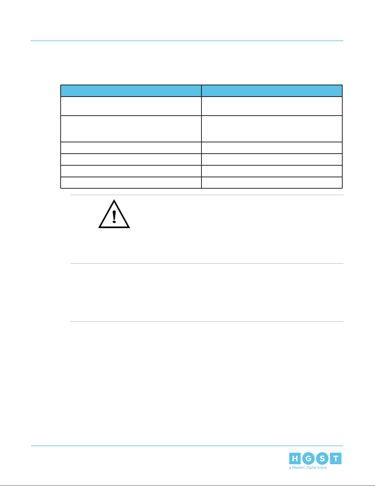
3.7 Safety Warnings and Cautions
To avoid personal injury or property damage, before you begin installing the product, read, observe, and
adhere to all of the following safety instructions and information. The following safety symbols may be used
throughout the documentation and may be marked on the product and/or the product packaging.
CAUTION Indicates the presence of a hazard that may cause minor personal injury or property damage
if the CAUTION is ignored.
WARNING Indicates the presence of a hazard that may result in serious personal injury if the WARNING
is ignored.
Indicates potential hazard if indicated information is ignored.
Indicates shock hazards that result in serious injury or death if safety instructions are not followed.
Indicates do not touch fan blades, may result in injury.
Indicates disconnect all power sources before servicing.
27
Page 28

4 Packaging
Installation Guide 4.1 Ultrastar Serv60+8 Packaging Overview
Chapter
4 Packaging
4
4.1 Ultrastar Serv60+8 Packaging Overview
Figure 6: Packaging Layout
The Ultrastar Serv60+8 packaging consists of three layers of packaging: The accessory tray is on top, the
enclosure chassis box is in the middle, and the drive assemblies are on the bottom. The accessory tray
contains two cartons, one for the CMA assembly and one for the rails, as well as plastic bags that contain all
necessary hardware listed below in the tables and the included cables. The chassis is boxed in the middle
and protected by foam padding. It has the rear fans, PSUs, and IOM pre-installed. On the bottom there are
four containers that hold fourteen HDD drive assemblies and one container that holds four,and one container
that holds the eight SSDs includedinside the Ultrastar Serv60+8.These three layersofpackagingare contained
by cardboard caps on the top and bottom, and an outer sleeve that surrounds the sides. Plastic banding
surround the packaging and pallet to keep them contained.
Table 16: Box Contents
ContentsContainer
CMA armCMA Box
Accessory Tray
28
• 2 Top Cover Guide Brackets
Page 29

4 Packaging
Installation Guide 4.2 Ultrastar Serv60+8 Unpacking Procedure
ContentsContainer
• 2 Rack Latch brackets (One Left, One
Right)
• Screws & Nuts
10 M5 Cagenuts
30 M5 x 12, T15 Torx screws
2 M5 x 12 Philips Panhead screws (for
cover retention)
16 Custom Round Washers
• Cables
2 C13 to C14 Power Cables (3m)
2 Rack Rails w/ 1 Inner Rail per Rack RailRails Box
Chassis
5 Drive boxes
Chassis w/ all internal components pre-installed except
drives and SSDs.
4 with 14 driver per container, 1 with 4 HDDs and 8 SSD
assemblies.
4.2 Ultrastar Serv60+8 Unpacking Procedure
1. Make sure that all of the necessary equipment is available, including any equipment necessary to support
the enclosure during installation. To verify the list of necessary equipment, see: Table 16: Box Contents
on page 28.
2. Cut the straps that secure the packaging to the pallet with a box cutter.
29
Page 30

4 Packaging
Installation Guide 4.2 Ultrastar Serv60+8 Unpacking Procedure
3. Remove the top cap and the outer sleeve and discard them both.
Figure 7: Top Cap and Sleeve Removal
30
Page 31

4 Packaging
Installation Guide 4.2 Ultrastar Serv60+8 Unpacking Procedure
4. Open the rail box and remove the two rail assemblies. Set them aside.
Figure 8: Accessory Tray
5. Open the CMA box and remove the two CMA arms and the cross-bar. Set them aside.
6. Open the chassis box and remove the top cushions, on the front and rear of the chassis.
Figure 9: Unpack Chassis
31
Page 32

4 Packaging
Installation Guide 4.2 Ultrastar Serv60+8 Unpacking Procedure
7. Remove the chassis itself from the chassis box. The chassis should be team lifted for safety.
8. Open the HDD boxes and verify their contents. Depending on the version of the Ultrastar Serv60+8 being
unpacked,theyshouldcontain four containers that holdfourteen HDD driveassembliesandone container
that holds four,and one container that holds the eight SSDs included inside the Ultrastar Serv60+8. Once
the contents are verified, leavetheminthe boxes.Thiswillprotect them from damage until they are installed
in the enclosure.
Figure 10: Inspect Drives and Drive Blanks
32
Page 33

5 Installation
Installation Guide 5.1 Ultrastar Serv60+8 Installation Overview
Chapter
5 Installation
5
5.1 Ultrastar Serv60+8 Installation Overview
Table 17: Procedure Info
Required PartsRequired Tools
Long T15 TorxScrewdriver
• # 2 Philips Screwdriver
• Long T10 TorxScrewdriver
• Tape Measure
• Level
Table 18: Torque Specifications for Screws
Torque ValueScrew Type
3.38-3.61 Nm / 30-32 in-lbfM5 x 10mm T15 Torx screws
3.38-3.61 Nm / 30-32 in-lbfM5 x 12mm Phillips Pan Head screws
•• M5 x 10mm T15 Torx
screws
• M5 x 12mm Phillips Pan
Head screws (to secure
top cover)
• Included Washers
• Low-Profile M4 x 3.2mm
Philips screws (included
with rail assembly)
• M3 x 8mm T10 Torx
screws
• 10 M5 cage nuts
• Zip Tie (from CMA box)
# of People
Required
Lifting Purposes
and 1 to Guide and
Spot)
Time
Required
45 min.3 Total (2 for Team
.90-1.12 Nm / 8-10 in-lbfLow-Prole M4 x 3.2mm Philips screws
.33-.56 Nm / 3-5 in-lbfM3 x 8mm T10 Torx screws
5.2 Ultrastar Serv60+8 Installation Procedure
1. Remove the inner rail that is nested inside the rack rails.
Note: There are Right and Left rails and they must be installed as a set. Each inner rail will read
"R" for the right or "L" for the left embossed on the inside. Each outer rail will read "R-Front" for
the right or "L-Front" for the left. Right and Left refer to when you are facing the front of the rack.
a) Start by sliding the inner rail out of the outer/rack rail until the safety latch engages and the inner rail
will not extend further. It will only slide one way.
33
Page 34

5 Installation
Installation Guide 5.2 Ultrastar Serv60+8 Installation Procedure
b) Press on the safety latch release spring located on the side of the rail and slide the inner rail out the
rest of the way.
Figure 11: Rail Safety Latch
2. Install the inner rail onto the chassis making sure they are installed on the correct side. Each inner rail
will read "R" for the right or "L" for the left embossed on the side that faces away from the chassis. Right
and Left are with reference to looking at the front of the enclosure.
a) Orient the inner rails so that the flat side is facingthe enclosure and the side with the grooves is facing
away from the enclosure.
34
Page 35

Screw
Screw
Screw
Click
Click
5 Installation
Installation Guide 5.2 Ultrastar Serv60+8 Installation Procedure
b) Align the keyholes on the inner rail to the mounting pegs on the side of the enclosure and press the
inner rail flush against the chassis. If the keyholes don't line up with the pegs, flip the rail length-wise
to see if this will align them.
Figure 12: Inner Rail Attachment
c) Slide the inner rail toward the rear of the chassis to lock it in place. There will be an audible click and
the mounting pegs will cover the front part of the keyhole.
Figure 13: Slide Inner Rail
d)
Caution: When installing the inner rail onto the chassis, make sure to only use the
special Low-Profile M4 x 3.2mm Philips screws provided in the accessory kit with the CMA.
These screws should be tightened to .90-1.12 Nm / 8-10 in-lbf using a # 2 Philips Screwdriver.
These screws are specially designed for this purpose. Using unapproved screws could cause
damage to the slides inside the rail.
Install the three special low-profile M4 x 3.2mm Philips screws provided to secure the inner rail to the
chassis.
35
Page 36

Click!
5 Installation
Installation Guide 5.2 Ultrastar Serv60+8 Installation Procedure
e) Follow these steps for the second inner rail on the opposite side of the enclosure.
3. Set the vertical rack rail depth to between 32" and 36".
Note: Ensure that all of the vertical rails are set to the same depth using a tape
measure.
4. Install the outer rails into the rack. Pay special attention to which side is being installed. The embossed
R is for the right side and L is for the left side. Right and Left refer to when you are facing the front of the
rack.
a) Move to the rear of the rack.
b) Orient the rail so that the word "REAR" that is embossed into the metal of the rail is at the rear end
of the rack, and the release latch is facing the inside of the rack posts as shown in the following image.
Figure 14: Rear Rail Latch Release Latch
c) Align the rail on the rack posts at the U-height desired for installation. The bottom of the rail will be
the lower most U of the total 4U height.
d) Pull the rail toward the rack post until the toolless latching mechanism engages the rack. The latching
mechanism may need to be pulled open to get around the rack post.
e) Move to the front of the rack.
36
Page 37

Click!
5 Installation
Installation Guide 5.2 Ultrastar Serv60+8 Installation Procedure
f) Align the front of the rail with the holes on the rack posts that will receive the rails and pull the rail
toward the holes until the toolless latching mechanism engages the rack.
Figure 15: Front Rail Release Clip Operation
g) Use a level to make sure that the rails are aligned properly.
h) Follow these steps for the other outer rail.
5. Install five M5 cage nuts, per side, starting at the uppermost rack mounting hole of the 4U space on the
front of the rack.
a) Install one cagenut at the uppermost mounting hole of the 4U space that the enclosure will occupy.
37
Page 38

5 Installation
Installation Guide 5.2 Ultrastar Serv60+8 Installation Procedure
b) If the Ultrastar Serv60+8 will be installed in a rack for shipping purposes, install four more M5 cage
nuts in the holes 3-6 of the 4U space. These will receive the M5 x 10mm T15 Torx screws that secure
the enclosure to the rack with the shipping bracket.
Figure 16: Cage Nut Spacing
6. Install the rear cover alignment brackets.
38
Page 39

5 Installation
Installation Guide 5.2 Ultrastar Serv60+8 Installation Procedure
a) From the rear of the rack, orient the alignment brackets so that the groove that will catch the cover is
facing the inside of the rack.
Figure 17: Alignment Bracket Groove (highlighted in red)
b) Use five of the M5 x 10mm T15 Torx screws and five of the included washers and attach the rear
coveralignment bracket to the vertical rail with the Long T15 Torx Screwdriver. Add three M5 x 10mm
T15 Torx screws and three included washers to attach the rear rail (the three lower holes) to the rack
posts as shown in the following image. These screws should be tightened to 3.38-3.61 Nm / 30-32
in-lbf using a Long T15 Torx Screwdriver.
Figure 18: Screw and Washer Order
39
Page 40

ScrewLocations
5 Installation
Installation Guide 5.2 Ultrastar Serv60+8 Installation Procedure
Caution: Be careful to set the screw properly into the cage nuts to prevent
crossthreading.
Figure 19: Screw Installation Location
7. Install the two rack latch brackets at the front of the rack.
a) Orient the brackets so that the screw holes are between the two pins supporting the outer rails as
shown in the following image. There is a left and a right. Use the image below as a guide for how to
40
Page 41

5 Installation
Installation Guide 5.2 Ultrastar Serv60+8 Installation Procedure
orient this bracket and mirror it for the other side. Notice the increased distance between the top two
screw holes and the lower screwholes and the flange being oriented on the outside.
Figure 20: Rack Latch Bracket Installed
b) Use 6 of the included M5 x 12mm screws and the T15 Torx screwdriver to install each bracket, 3
screws per bracket.
Caution: Always install the top cover onto the enclosure before installing the chassis into a rack.
Not having the top cover installed may damage the alignment brackets.
41
Page 42

5 Installation
Installation Guide 5.2 Ultrastar Serv60+8 Installation Procedure
8. Extend the mid-rails out of the rack so that they are protruding from the front of the rack and the safety
latches engage.
Figure 21: Extend Mid-Rails
9. Install the chassis into the rails.
a)
Caution: Thisstepinthe installation requires a minimumof 3 individuals to install safely,
two to lift and one to guide the others whom may have difficulty seeing because the enclosure
is in the way. Ensure that the appropriate measures are taken to safely support the enclosure
during installation. The enclosure MUST have no drives installed and requires a two person
team lift to install. Do not attempt to lift the system if it is fully populated with drives. The
only case in which the system may be installed or removed with the drives populated is if the
facility has a lift that is rated to handle the maximum weight of the fully loaded system.
Warning: Do not lift the chassis by the Cable Tray while removing the chassis from the
rack OR while installing it into a rack. This can cause serious damage to the unit or serious
42
Page 43

5 Installation
Installation Guide 5.2 Ultrastar Serv60+8 Installation Procedure
bodily harm to those handling the unit. Always team lift the chassis by gripping the underside
of the unit, and never try to lift a chassis that is filled with drives.
Figure 22: Bearing Plate
Figure 23: Installing the Chassis
43
Page 44

5 Installation
Installation Guide 5.2 Ultrastar Serv60+8 Installation Procedure
b)
Caution: Makesure that the bearing plate on the inside of the mid-rails are fully forward
and that the detent has engaged. This is to prevent potential damage due to improper mating
of the rails.
Positiononeindividual on each side of the enclosure to perform a team lift and have the third individual
standing at the protruding rack rails to guide the chassis to mate with rack rails.
c) Team-lift the enclosure until the inner rails that are attached to the chassis align with the extended
mid-rails attached to the rack, and guide the inner rails on the chassis to mate with the rack rails.
d) Once the rails are mated properly, slide the enclosure into the rack until it is stopped by the safety
catch on the rails. Push the release lever on the safety latch located on the side of each of the rails
and push the enclosure the rest of the way into the rack.
Figure 24: Safety Latch Release
e) As the chassis is slid into the rack, position one installer at the rear of the rack to ensure that the pegs
on the sides of the cover will slide correctly into the rear cover alignment brackets on both sides of
the rack. If the chassis does not install smoothly or snags, check that the rear coveralignment brackets
are not interfering with the chassis sidewalls, and try again.
10. Install the CMA.
a) Orient the CMA so that the elbow is on the left hand side.
44
Page 45

5 Installation
Installation Guide 5.2 Ultrastar Serv60+8 Installation Procedure
b) Attach all of the connectors to the bracketsonthe rails and chassis. There should be one at the elbow
side and two at the other end.
Figure 25: CMA Orientation
c) Slowly slide the enclosure forward to ensure the CMA arm is operating properly, then slide it back
into the rack.
11. Cable the CMA.
a) Unlatch the elbow side of the CMA arm and swing it forward by pressing the blue button that says
“push” to unlatch it.
45
Page 46

5 Installation
Installation Guide 5.2 Ultrastar Serv60+8 Installation Procedure
b) Open all of the baskets
Figure 26: Open Baskets
c) Route all of the cables being connected to the enclosure through the open baskets.
d) Close all of the baskets.
e) If the Ultrastar Serv60+8 is being installed in a rack and will subsequently be transported inside that
rack, it is important to use the included cable tie to wrap the CMA bundle to ensure it does not get
damaged during transport. If the Ultrastar Serv60+8 is instead being installed where it will operated,
skip this step. Remember to remove the cable ties after the enclosure has reached its final operational
location.
f) Reconnect the CMA at the elbow to the connectors on the rail.
12. Test for binding in the extension of the CMA by gently pulling the enclosure out of the rack to ensure the
cables extend properly and that the system doesn’t bind at all. If it does, examine the point at which the
binding occurred and adjust the seating of cables in the baskets, check the connections to the rails, and
examine the joints of the CMA arm to ensure that they are all functioning properly.
13. Make sure the CMA is in operational position by folding the arm in toward the enclosure and attaching
the elbow end of the CMA to the connector that is attached to the rail. Verify that all of the cabling is in
functional order and does not bind or catch.
46
Page 47

5 Installation
Installation Guide 5.2 Ultrastar Serv60+8 Installation Procedure
14. Secure the chassis top cover to the rack using the included washers, the M5 x 12mm Phillips Pan Head
screws, and a Philips screwdriver as shown in the following image. These screws should be tightened
to 3.38-3.61 Nm / 30-32 in-lbf using a # 2 Philips Screwdriver.
Figure 27: Cover Retention Screws
15. Now that the chassis is installed, test the installation by sliding the enclosure in and out of the rack a
minimum of three times. If the enclosure binds, catches, or displays any incorrect motion or behavior
retry the installation.
Note: Adjustments of the vertical rack rails may be required to fix any issues that may
occur.
16. Grasp both handles at the front of the enclosure and pull with even pressure to extend the chassis out
of the rack until it is stopped by the safety latches. The safety latches will prevent the enclosure from
coming out of the rack completely and the cover will remain in the rack attached to the rear alignment
brackets.
Figure 28: Chassis Handle Operation
17. Perform this same action two more times without the drives loaded to make sure the rail kits are installed
properly.
18. Install the Drive Assembly.
a) Ensure that the enclosure has been pulled out of the rack until the rail latches engage.
47
Page 48

REAR
FRONT
5 Installation
Installation Guide 5.2 Ultrastar Serv60+8 Installation Procedure
b) Find the LED pointer on the top of the drive carrier. This pointer should point toward the front of the
unit as shown in the following image.
Figure 29: LED Pointer Orientation
48
Page 49

5 Installation
Installation Guide 5.2 Ultrastar Serv60+8 Installation Procedure
c) Align the drive with the empty slot that will receive it. Lower it into the slot, making sure it stays level
and does not snag.
Figure 30: Installing a Drive Assembly
d) Pinch the latch release and carefully press downward to seat the Drive Assembly the rest of the way.
49
Page 50

5 Installation
Installation Guide 5.2 Ultrastar Serv60+8 Installation Procedure
19. Install each drive in the same way the first was installed. Make sure to follow the drive layout shown in
the following image.
Figure 31: Drive Layout
20. Now that the drives are installed into the chassis, test the installation by sliding the enclosure in and out
of the rack a minimum of three times. If the enclosure binds, catches, or displays any incorrect motion
or behavior retry the installation of the drives and chassis.
21. If the chassis is being installed into a rack that will be shipped fully assembled, you must install eight
(fourperside)of the included M5 x 10mmT15 Torxscrewsintothetwobracketsatthefrontof the chassis
in the following locations. These screws should be tightened to 3.38-3.61 Nm / 30-32 in-lbf using a Long
50
Page 51

ScrewLocation
5 Installation
Installation Guide 5.2 Ultrastar Serv60+8 Installation Procedure
T15 Torx Screwdriver. If this chassis will not be installed into a rack for shipping purposes, skip this step
and move on to the next one.
Figure 32: Shipping Bracket Screw Locations
22. Plug the enclosure power cords into a PDU to power the enclosure.
23. Press the power button at the back of the enclosure to power it up.
24. Double check the power indicators and other LEDs to ensure that the system is booting.
51
Page 52

Installation Guide
Chapter
6 Points of Contact
6
For further assistance with an HGST product, contact Platform Engineering technical support. Please be
prepared to provide the followinginformation: Serial Number (S/N), product name, model number,and a brief
description of the issue.
Email:
support@wdc.com
Website:
http://support.hgst.com
6 Points of Contact
52
 Loading...