

Page 1
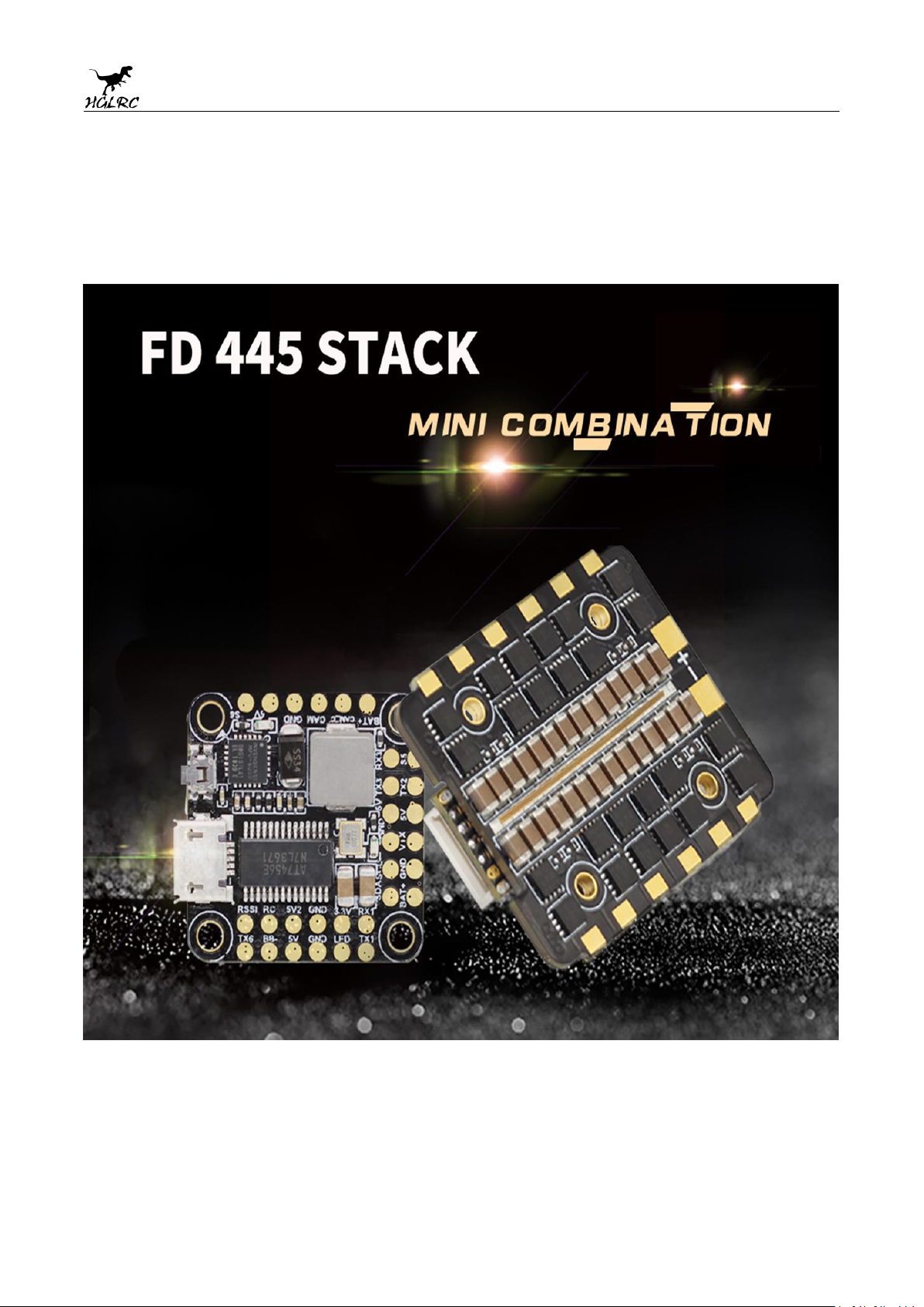
Forward FD445 Stack
Manual
1
www.hglrc.com
Page 2

Product Specifications.............................................................................................................................1
Forward FD445 Stack
*1
Accessory Bag*1
Interface Description...............................................................................................................................2
Check the flight control drive................................................................................................................3
Calibration accelerometer......................................................................................................................4
URAT serial port use.................................................................................................................................5
Select aircraft model.................................................................................................................................6
Choose ESC protocol..................................................................................................................................7
Select ESC telemetry..................................................................................................................................8
Voltage and current parameters setting............................................................................................9
Setting up the receiver..............................................................................................................................10
VTX serial port use. VTX uses OSD smart audio..............................................................................11
GPS parameters setting...........................................................................................................................12
Check receiver signal................................................................................................................................13
Select flight mode startup mode...........................................................................................................14
OSD settings.................................................................................................................................................15
LED settings.................................................................................................................................................16
Troubleshooting.........................................................................................................................................17
.......................................................................................
Package IncIuded
2
www.hglrc.com
Page 3

1.Product Specifications
Forward FD445 Stack
Product parameters
FC name
Forward F4 MINI Flight Control
Usage
for 110mm-1000mm Frame Kit
MPU
MPU6000-SPI
CPU
STM32F405R6T6, 8K
Firmware:
Betaflight OMNIBUSF4V6
Black Box
No dataflash chip found
Support receiver
SBUS .PPM .DSMX
ESC name
Forward 45A 4in1 MINI ESC
Continuous current
45A-4S/35A-6S
CPU
STM32F051
ESC firmware
BIheIi_32
Input Voltage
2-6S Lipo
BEC Output
5V@3A
Size
31.7X36.5mm board, 20*20mm
mounting holes(M2)
STACK Weight
15.5g
3
www.hglrc.com
Page 4

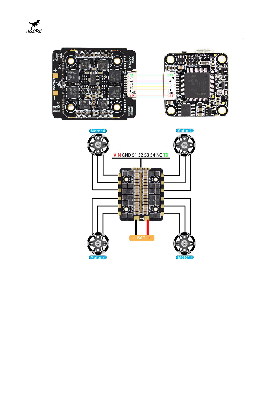
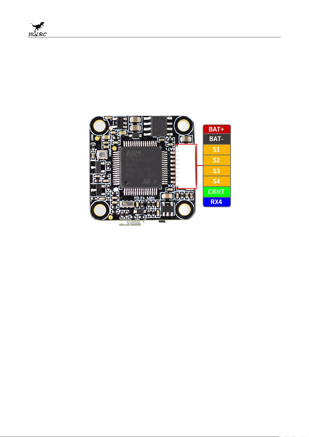
2.Interface Description
4
www.hglrc.com
Page 5
5
www.hglrc.com
Page 6
6
www.hglrc.com
Page 7
3.Check the flight control drive
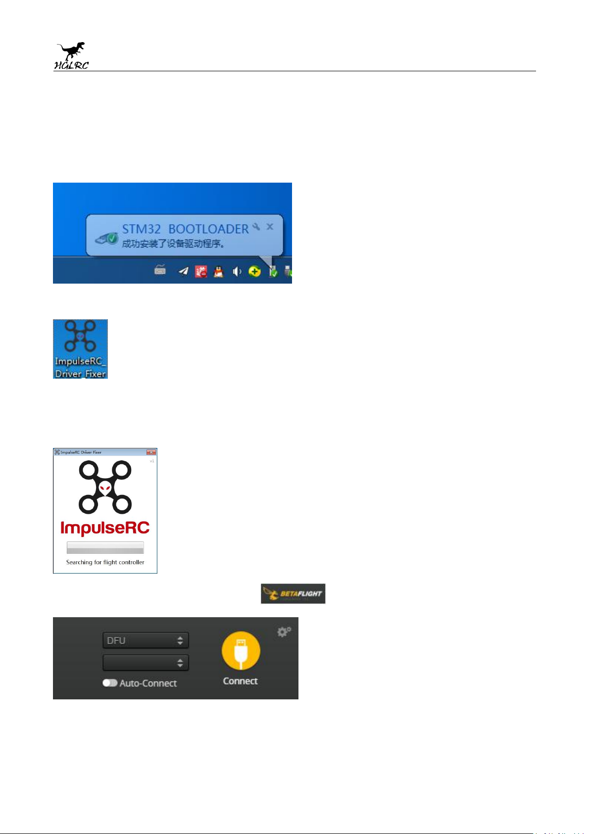
1. Long Press BOOT buttons.connect USB.The system automatically
install the driver
2.Driver cannot be installed, please download ImpulseRC_Driver_Fixer
3.Double-click on the run(Plug in the flight controller to automatically
install the driver)
4.open betaflight configurator ,enter DFU mode
7
www.hglrc.com
Page 8
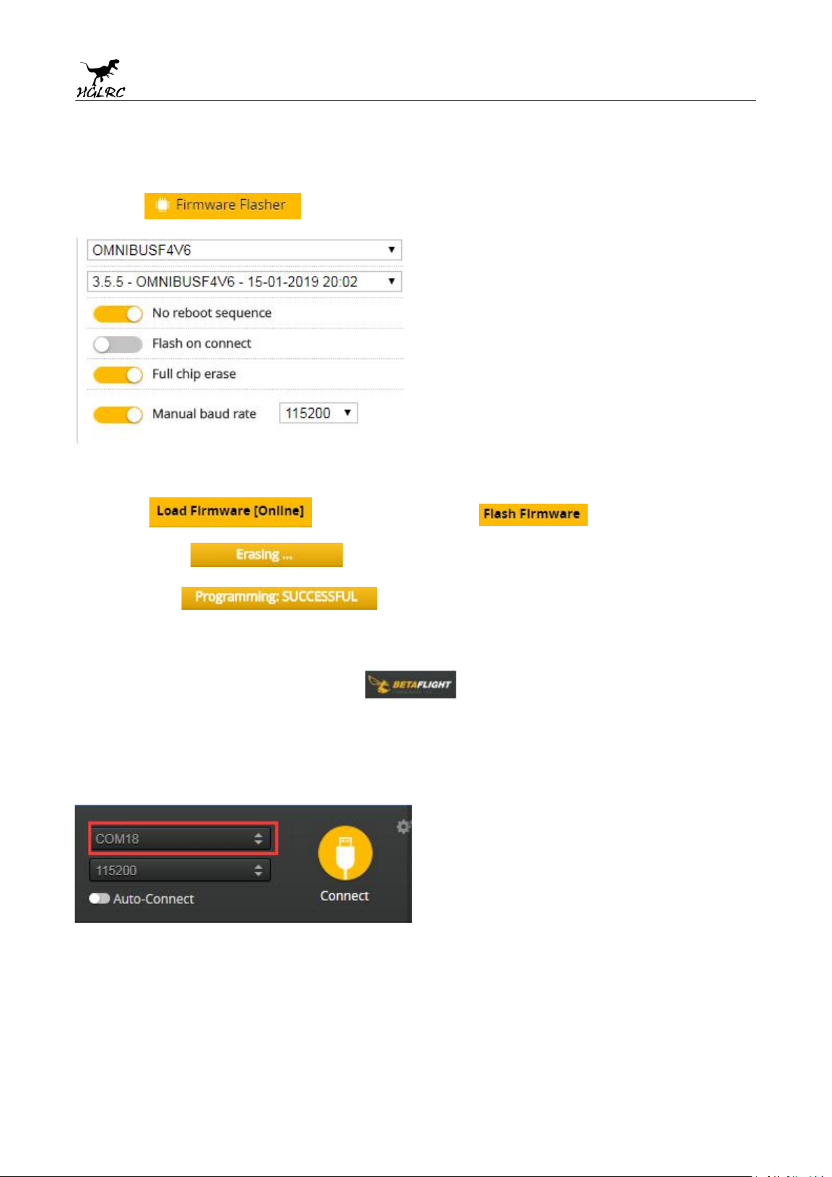
5.Click Select firmware version
6.Click Load firmware. Waiting for
completion It will be prompted upon
completion.
7.open betaflight configurator
Controller plugged into the
。
computer. Betaflight Automatically assigned port,click “Connect”
Enter setup interface(Different computer COM)
8
www.hglrc.com
Page 9
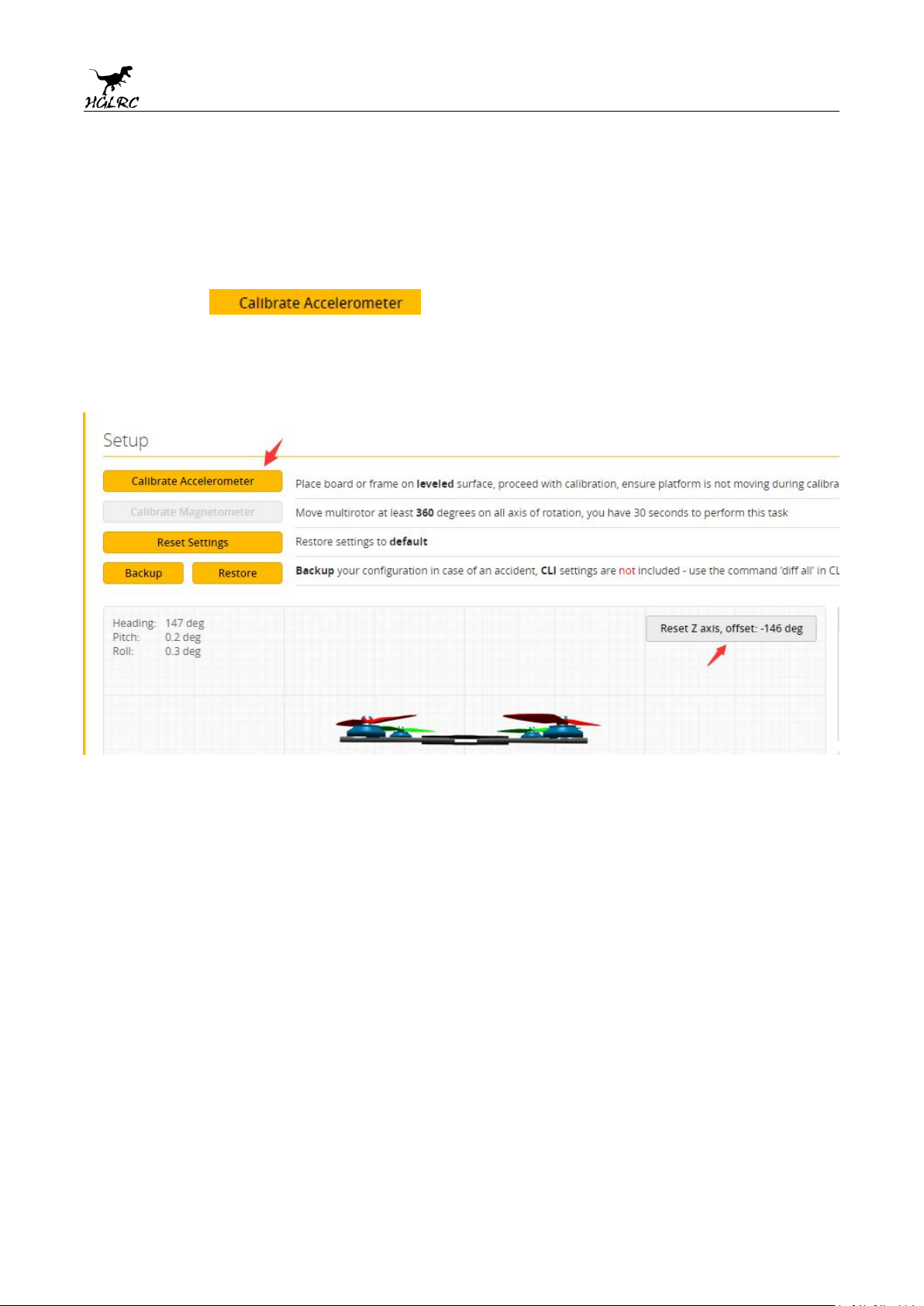
4. Calibration accelerometer
1. Put the aircraft horizontal and click“Reset Z axis”
Click again
9
www.hglrc.com
Page 10
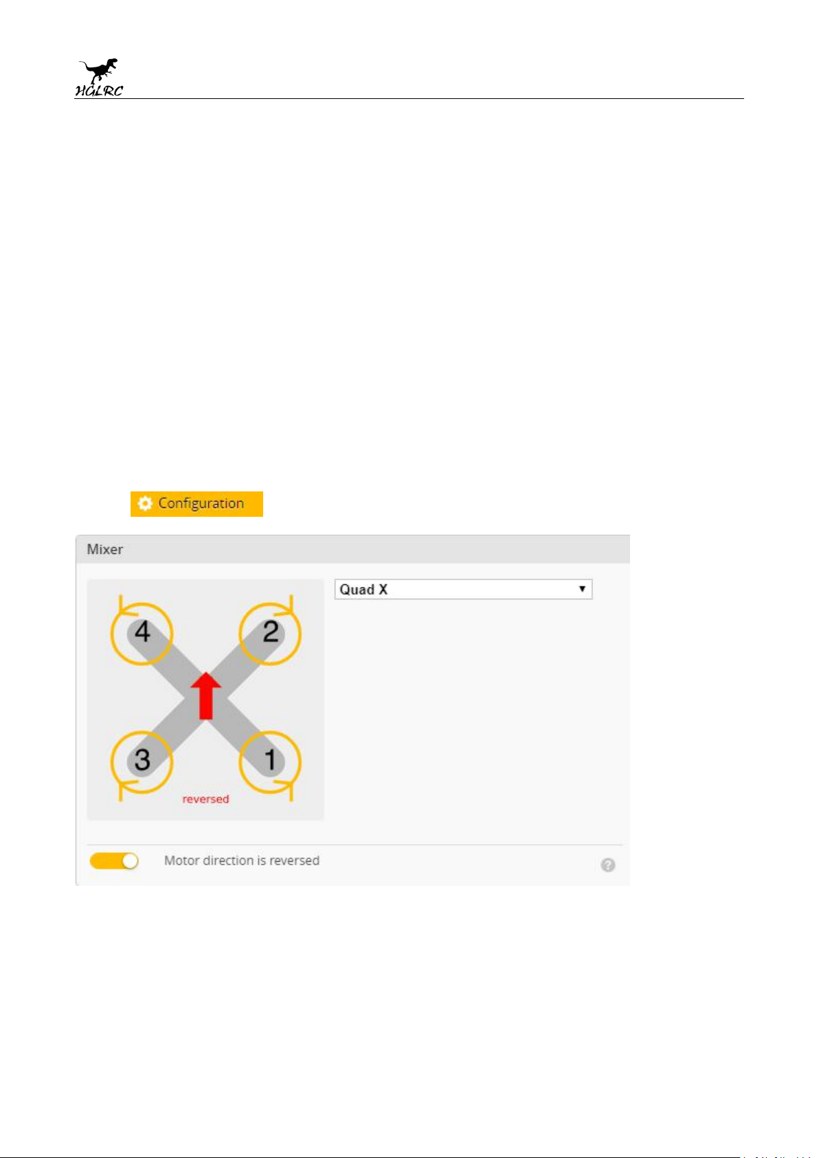
5.URAT serial port use
URAT1 uses receiver telemetry
UART2 uses VTX image transmission
UART3 uses GPS
UART4 uses ESC telemetry
URAT6 uses the receiver
6.Select aircraft model
1.Click Select model
10
www.hglrc.com
Page 11
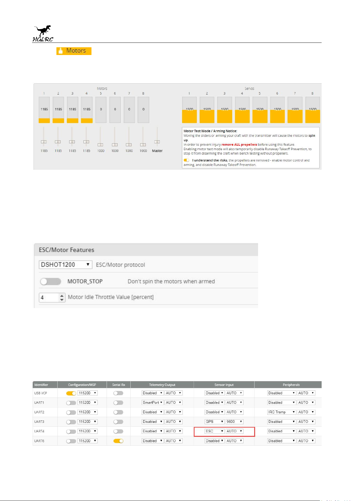
Click Click “I understand the risks”
2.
steering“Master”Steering can be changed at BLHeliSuite32
Push Master to check motor
7.Choose ESC protocol
1.Choose the right ESC protocol, the optional universal protocol
DSHOT600.For FD445, DSHOT1200 is recommended.
8.Turn on ESC telemetry
1.Open ESC telemetry serial port.TX on the ESC needs to be connected
to the RX4 on the flight controller to use the ESC telemetry
11
www.hglrc.com
Page 12
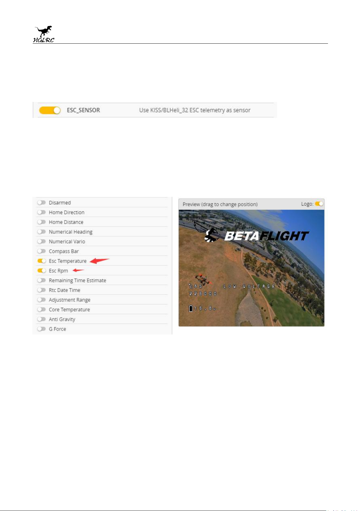
2.Use KISS/BLHeli_32 ESC telemetry as sensor.
3.View telemetry data on OSD
12
www.hglrc.com
Page 13
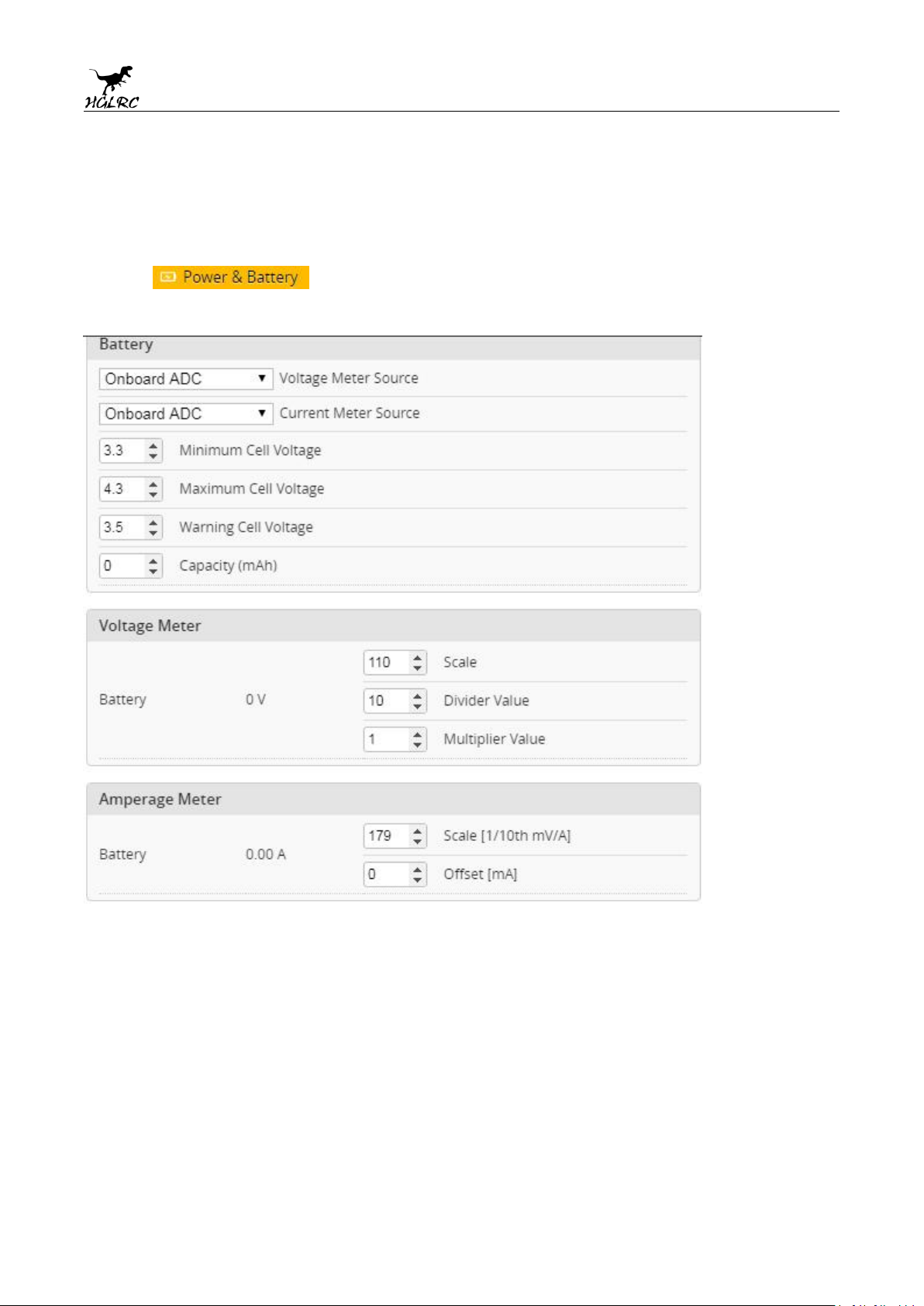
9.Voltage and current
1.
Click
Setting parameters
parameters setting
13
www.hglrc.com
Page 14
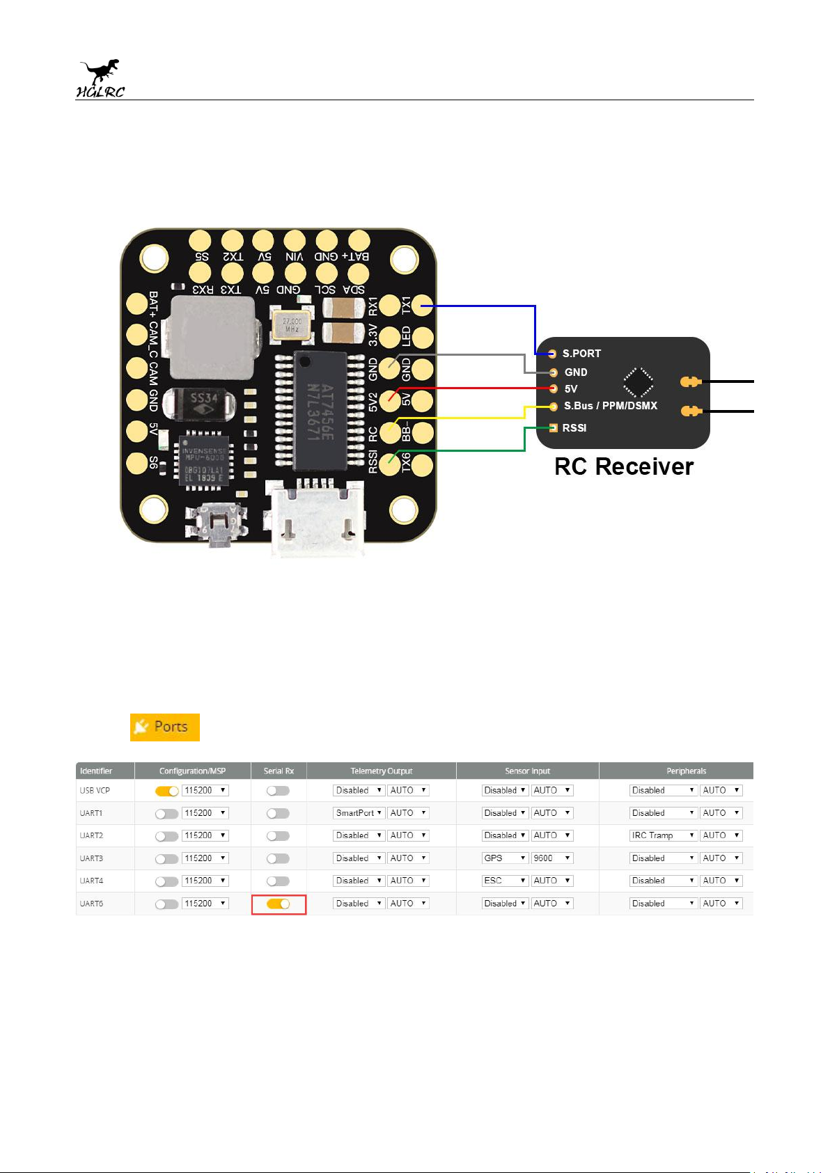
10. Setting up the receiver
1.Receiver connection diagram
2.Click
.have found
“
UART6”Open the receiver serial port
14
www.hglrc.com
Page 15
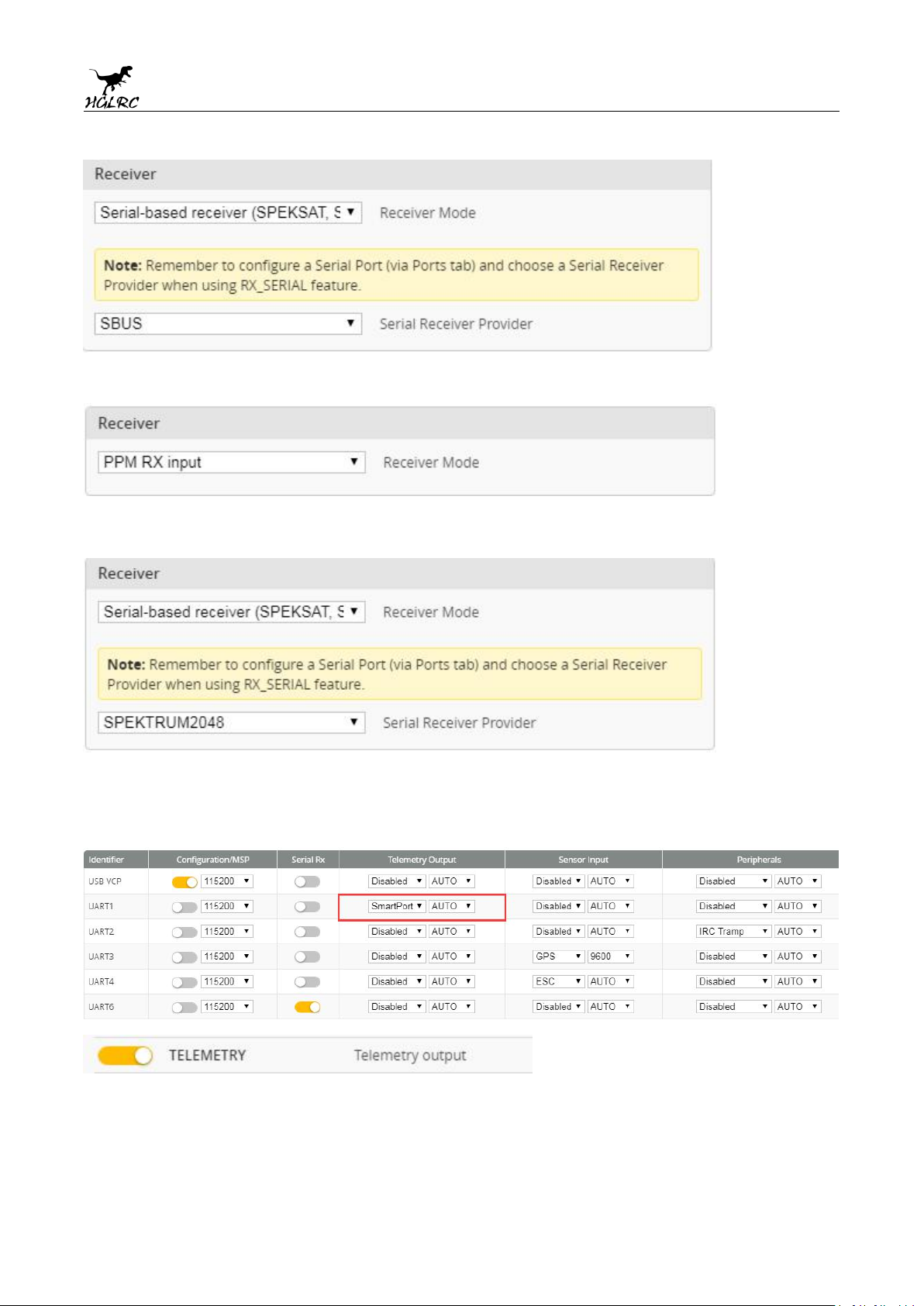
3.Set the SBUS receiver
4.Set the PPM receiver
5.Set the DSMX receiver
6.Turn on the receiver telemetry serial port Function on
15
www.hglrc.com
Page 16
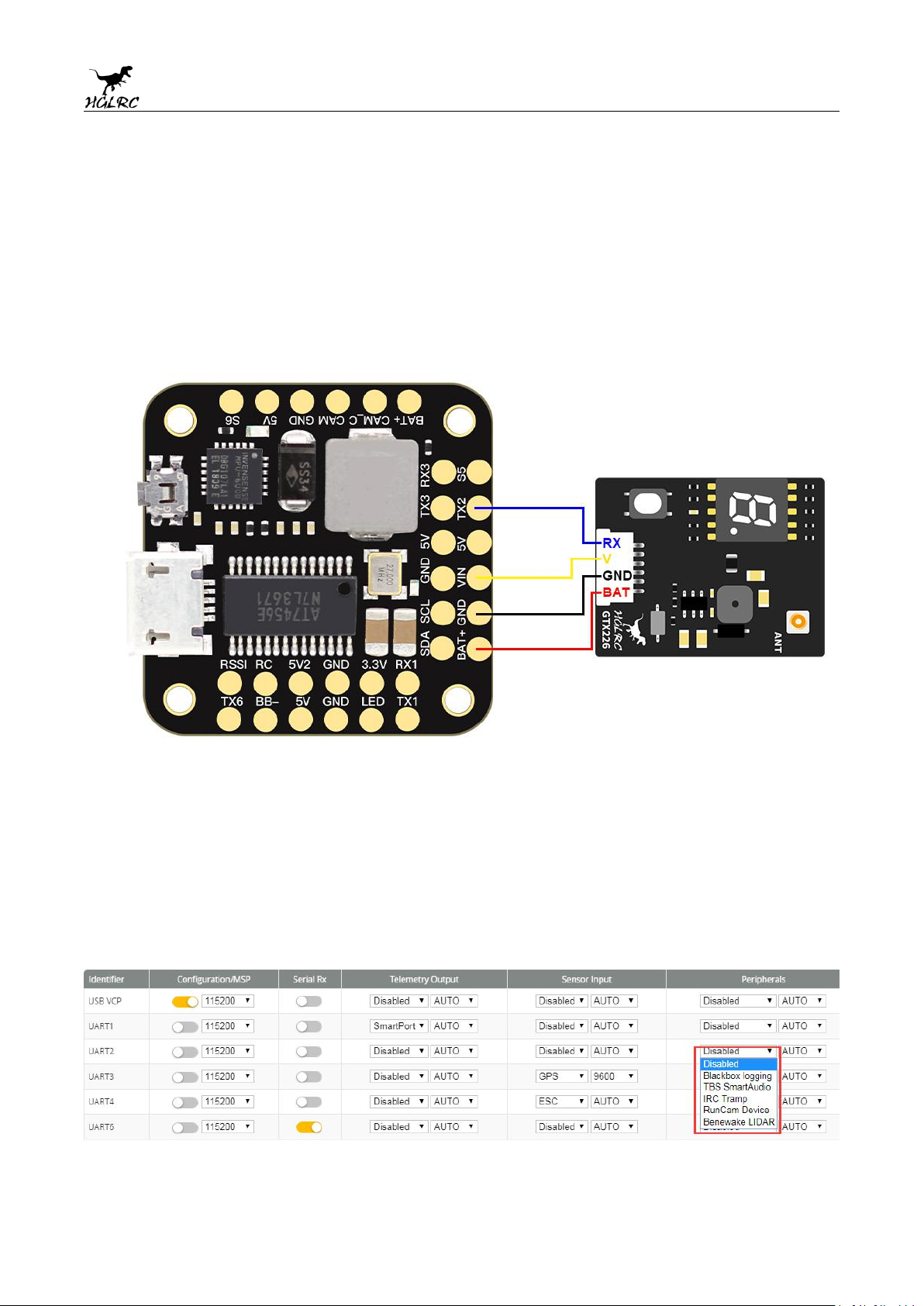
11.VTX serial port use. VTX uses
OSD smart audio
1.VTX connection diagram
2.VTX serial port opens. The protocol is selected according to its own VTX
protocol.
16
www.hglrc.com
Page 17
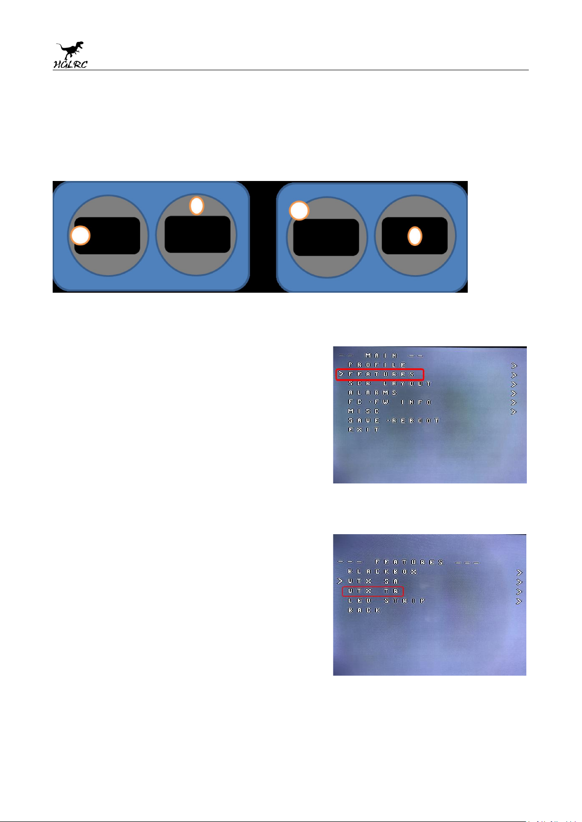
3.Use OSD to adjust VTX
which displays information like battery voltage and mAh consumed while you fly. In addition, the
Betaflight OSD can be used to configure the quadcopter, making in-field adjustments and tuning more
convenient.
MODE2 MODE1
The graphics above show the stick command to bring up the OSD menu. The stick command is: throttle
centered, yaw left, pitch forward. The exact stick command therefore depends on which mode your
transmitter sticks are in.
In the OSD menu, use pitch up/down to move the cursor
between menu items. When a menu option has a > symbol
to the right of it, this indicates that it contains a sub-menu.
Roll-right will enter the sub-menu. For example, in the
screen to the right, moving the cursor to “Features” and
then moving the roll stick to the right will enter the
“Features” sub-menu.
If you are using a video transmitter that supports remote
configuration, enter the “Features” menu to configure the
vTX. From there, enter either “VTX SA” if you are using
SmartAudio (TBS Unify) or “VTX TR” if you are using IRC
Tramp Telemetry.
To adjust PIDs, rates, and other tuning-related parameters,
enter the “Profile” sub-menu.
In the “Scr Layout” sub-menu, you can move the OSD
elements (like battery voltage, mAh, and so forth) around on
the screen.
The “Alarms” sub-menu lets you control when the OSD will
try to alert you that battery voltage is too low or mAh
consumed is too high.
17
www.hglrc.com
Page 18
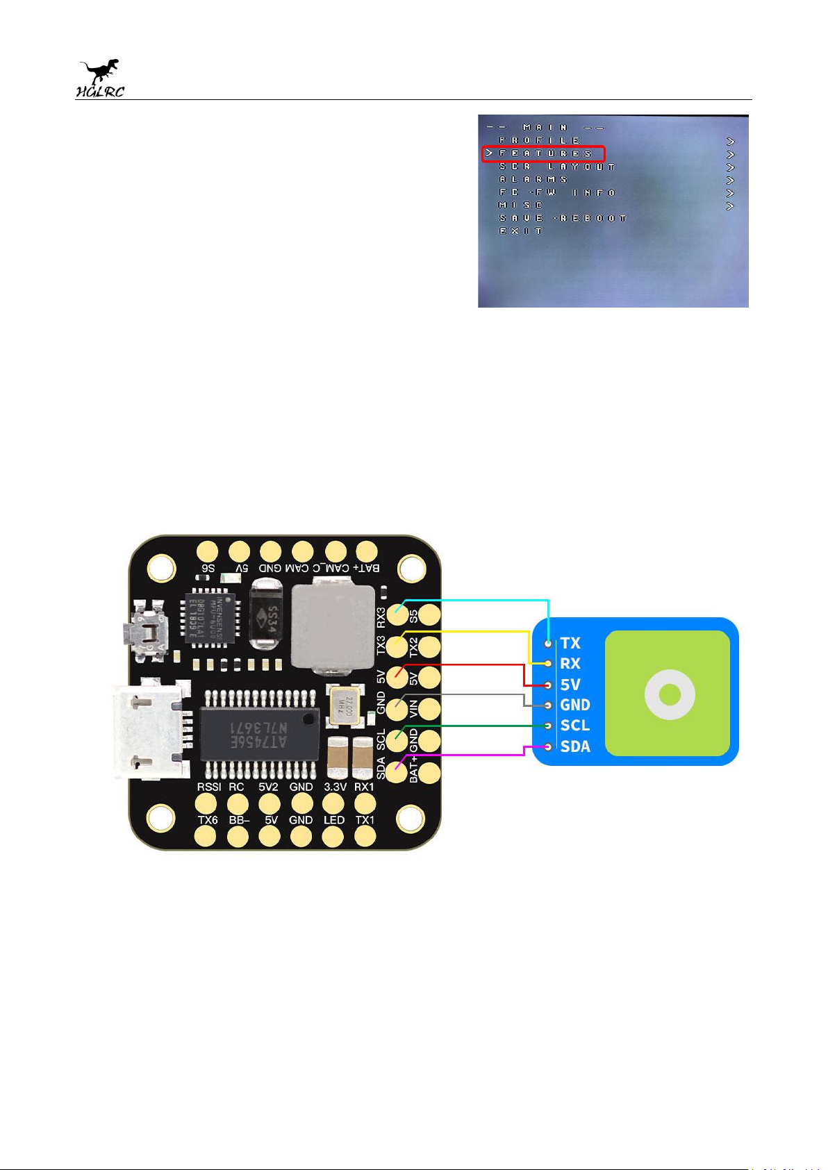
When a parameter can be modified, the parameter’s current
1. GPS connection diagram
value will be shown on the right-hand side of the screen. In
this case, roll left/right will adjust the parameter up and
down.
The screen to the right shows the current vTX settings. From
here, you can change the frequency band, channel, and
power level of the video transmitter. After making the
changes, move the cursor to “Set” and press roll-right to
confirm the settings.
12.GPS parameters setting
18
www.hglrc.com
Page 19
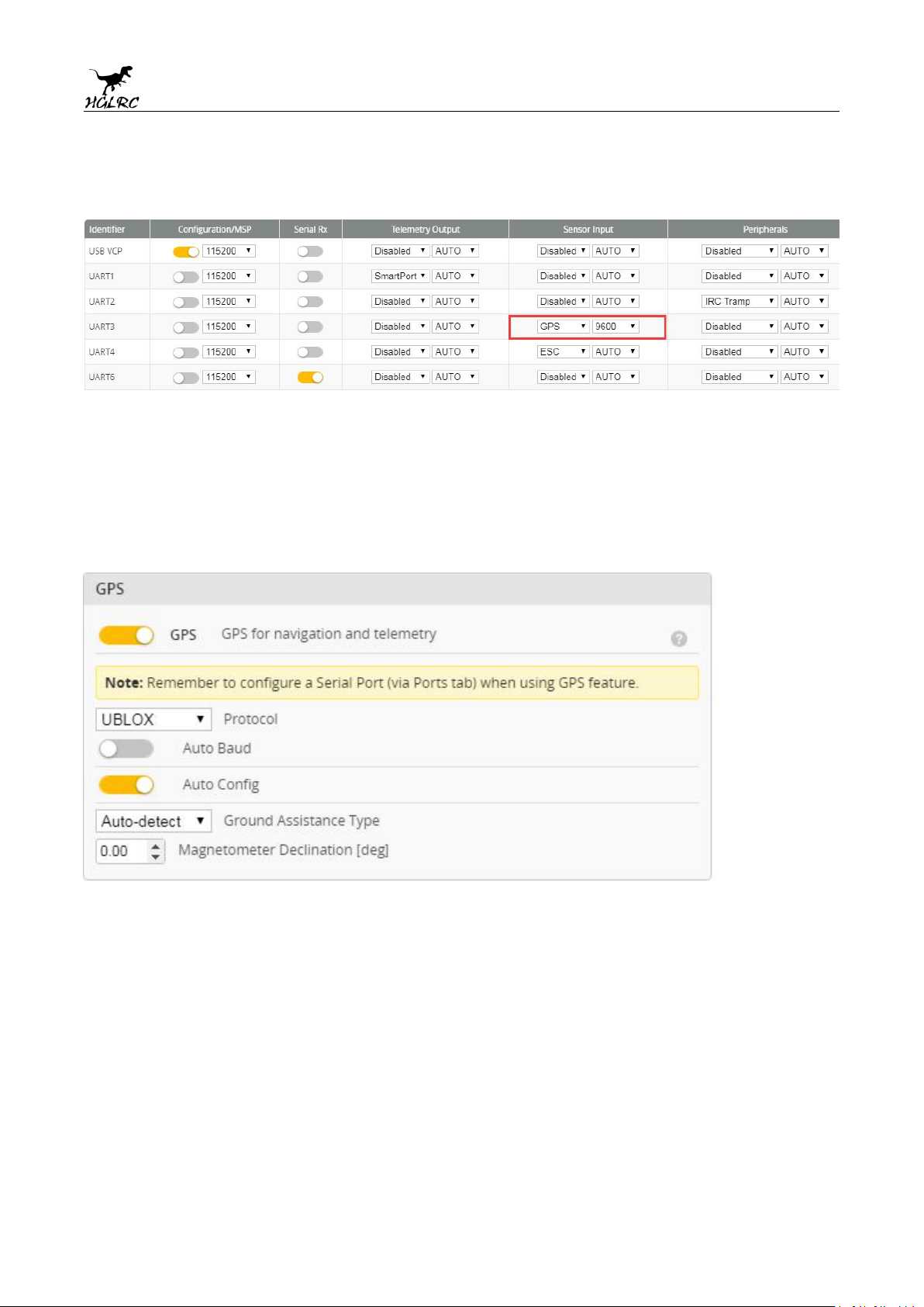
2. Open the GPS serial port
3.When using the GPS function, remember to configure the serial port
(via the Ports tab).
19
www.hglrc.com
Page 20
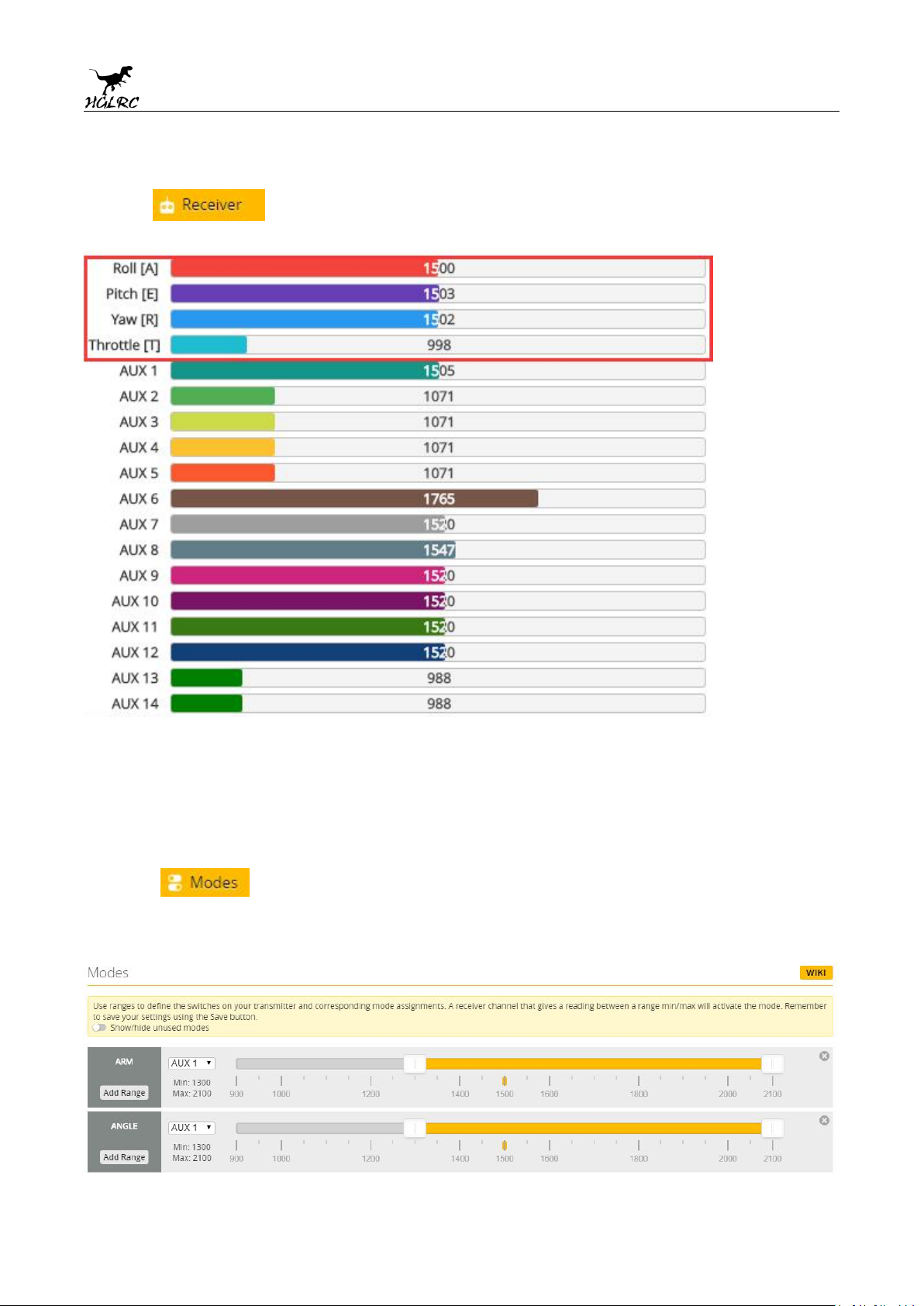
13.Check receiver signal
1.
Click Check the remote control output signal
1. Click set up the function of remote control switch across the
14.Select flight mode startup
mode
channel (below are for reference only)
20
www.hglrc.com
Page 21
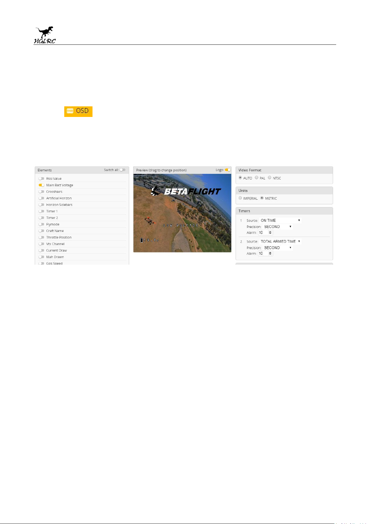
15. OSD settings
1. Click the OSD Settings, according to the need to choose, drag
the OSD schematic diagram of the parameters can be adjusted.
21
www.hglrc.com
Page 22
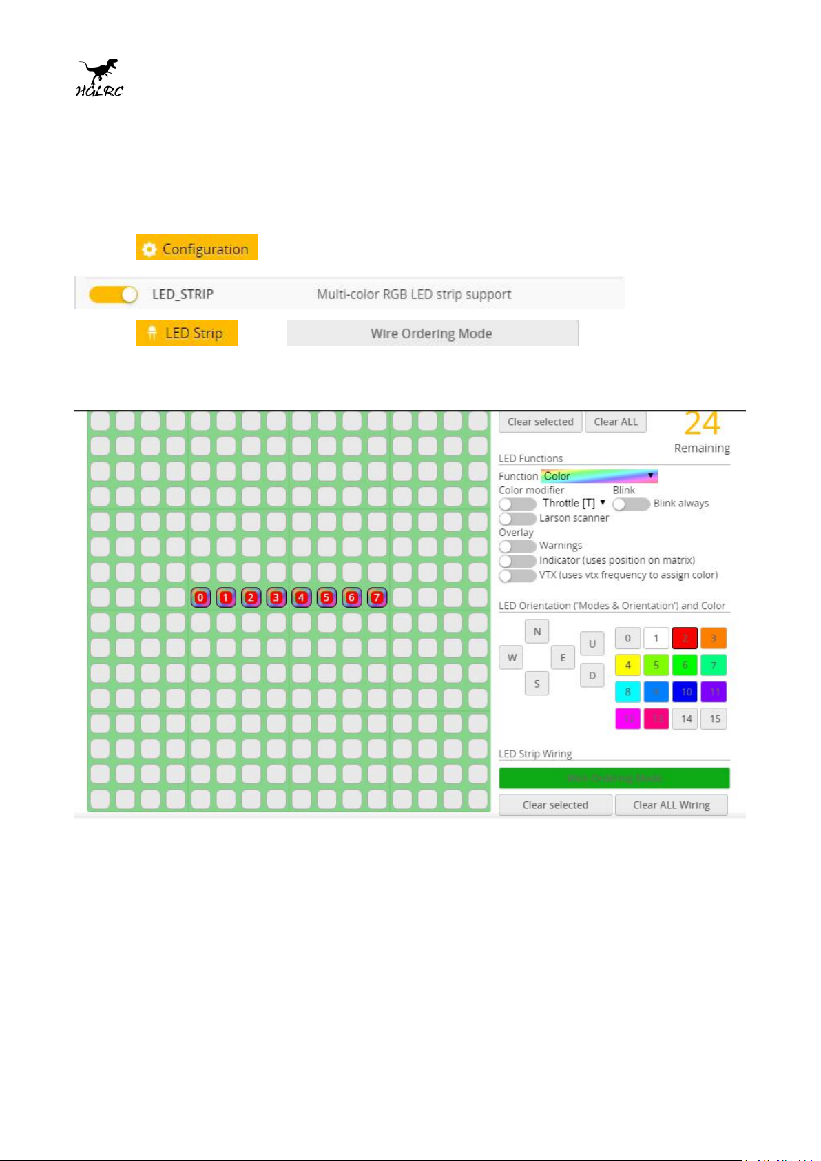
16. LED settings
1. Click Turn on LED support
2.Click .Click set according to
need
22
www.hglrc.com
Page 23

18.Troubleshooting
Warning:
Please read the cautions as follows, otherwise stability of your flight
controller cannot be ensured, your flight controller will even get damaged.
● Keep focus on the polarity. Check carefully before power supply.
● Cut off the power when you connect, plug and pull anything.
● The refresh rate of PID and Gyroscope is up to 32K/16K.
after sales question:
1. After receiving the goods, it is found that the product can not be used
normally. If the return to the factory is a quality problem, the repair
service will be provided free of charge.
2. If the product is damaged due to improper operation, the repair service
may be provided under the condition that the inspection can be repaired.
3. For domestic customers, please contact the after-sales service personnel.
For overseas customers, please contact the official website for after-sales
service.
23
www.hglrc.com
Page 24

Product daily problems
1. When plugged in the battery, the aircraft does not pass the self-test
1.OSD garbled:
If you find garbled characters, please open Betaflight, click “OSD” .and click “Font Manager”
clicks on “Upload Font” to update
without "BBB" sound. There is only one sound.
Please check if the ESC agreement is correct
3.The spin of the aircraft keeps spinning
1. Please check if the propeller is correct
2. Please check if the motor direction is correct
24
www.hglrc.com
 Loading...