

Page 1
USER INSTRUCTIONS
HFT PIPESTOPPERS
®
TM
© HFT
®
HFT Pipestoppers
®
ACCU-FREEZE™
(patented)
Page 2

PAGE 2
HFT PIPESTOPPERS
®
INDEX
Copyright © HFT®. All rights reserved.
This publication may not be reproduced by any means without the written
permission of Huntingdon Fusion Techniques HFT
®.
All logos, names, trademarks are the property and ownership of HFT®.
E&OE
Index 2
Operating Instructions 3
Safety Precaution when working with liquid nitrogen 3
General Information 3
System requirements to apply freeze seal 4
Freeze seal setups 4
Therma couple installation 5
AF 3000 Temperature Controller setup 6-8
Initiate Freeze Seal 8
Perform desired maintenance 9
Terminate Freeze Seal 9
Additional Information 9-14
HFT Pipestoppers
®
Product Range 15-16
Other languages in progress 17
Customer support and worldwide care 18
Warranty 19
Address and Contact Details 20
Page 3

PAGE 3
HFT PIPESTOPPERS
®
OPERATING INSTRUCTIONS
1. Safety precautions when working with liquid nitrogen (LN2)
1.1 LN2 can cause asphyxiation. Work in a well ventilated area.
1.2 Avoid freeze burns. Wear protective gloves, and a face shield when
tightening or opening LN2 connections.
1.3 To maintain the freeze plug during maintenance, duration of the work
must be considered before commencing. Consideration of additional LN2
tanks and methods to be used to change tanks during the freeze are
required to be pre-planned.
2. General information
2.1 Low pressure LN2 tanks are recommended for use. These are normally
supplied as 22 Psi tanks and 22 Psi is the minimum LN2 tank pressure
required for proper operation. The control solenoid valve is capable of
operating with a maximum of 60 Psi differential pressure.
2.2 Some familiarity with the LN2 tank pressure builder system, relief
systems and level indication system are required. Ask your gas supplier
how these systems work on the tanks you are using and how to tell when
the LN2 tank is nearing empty. These indications change with the tanks
you are using.
2.3 These tanks are normally congured with a Vent connection, and a
Liquid connection. Ensure the LN2 tank connection to the freeze coil is
made at the liquid connection.
Page 4

PAGE 4
HFT PIPESTOPPERS
®
Freeze times may vary due to actual working conditions. The pipe should
be at ambient temperature. If ambient temperature is in excess of 32˚C
(90˚F), add 15 minutes to the freeze time indicated in table 1 for every 4
degrees above 32˚C (90˚F) for pipe size up to 6", add 15 minutes to the
freeze time indicated in table 1 for every 2 degrees above 32˚C (90˚F) for
pipe size greater than 6". If the freeze is being performed in direct sunlight
some method of providing shade over the freeze area is recommended.
3. System requirements to establish freeze seal
3.1 Process uid must be static.
3.2 Pipe coating should be removed from area to be frozen.
3.3 Pipe should be free of dirt, oils, etc.
4. Freeze seal setups
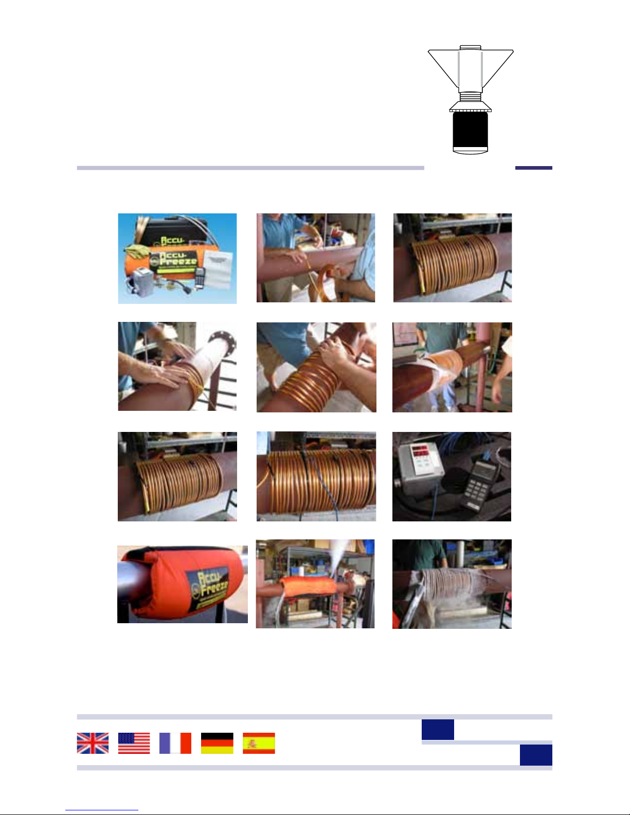
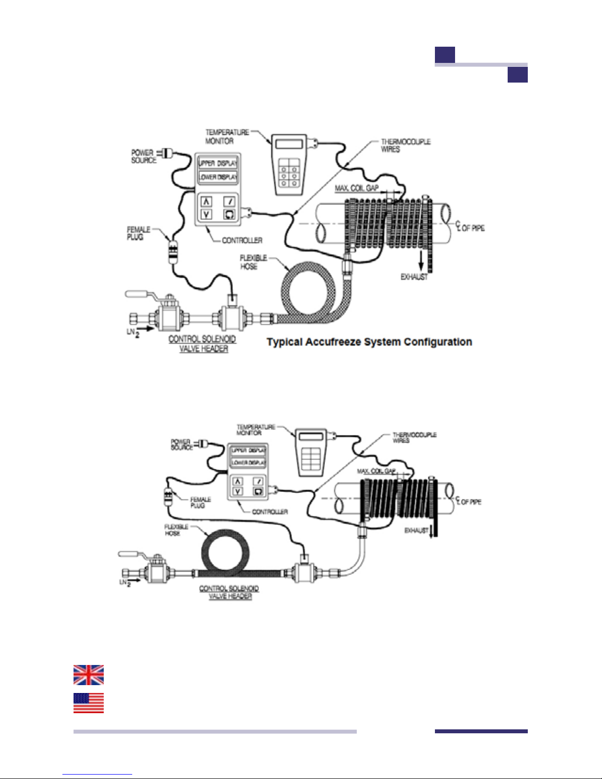
4.1 Coil copper tubing around freeze location (see table 1 for freeze
wrap recommendations). Copper tubing should be wrapped tightly with
each successive wrap in contact with previous wrap. Coil wraps may be
separated up to ¾ inche to allow for thermocouple placement (see 5.1
for direction on thermocouple placement).
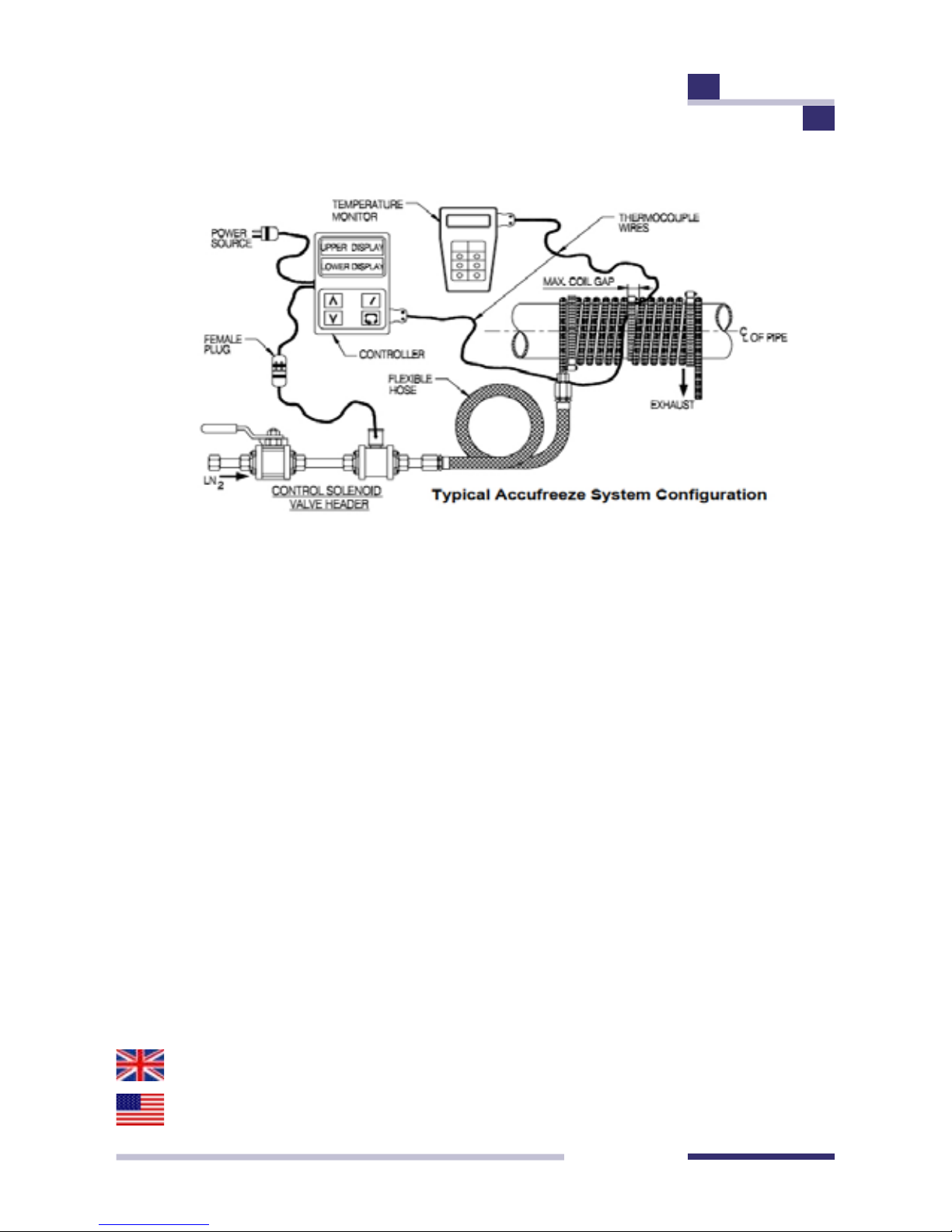
4.2 Connect the Control Solenoid Valve Header to the liquid
nitrogen (LN2) tank liquid supply and the LN2 supply exible hose to the
Control Solenoid Valve Header.
4.3 Check Control Solenoid Valve isolation valve closed.
OPERATING INSTRUCTIONS
Continued
Page 5

PAGE 5
HFT PIPESTOPPERS
®
4.4 Connect the exible hose to inlet side of wrap tubing.
4.5 Direct vented side of wrap tubing away from equipment thatmay be
damaged by Liquid Nitrogen emission. A catch bucket may be used.
Note: If more than one Control Solenoid Valve Header and exible supply hose is being used connect the system a described above and
connect the supply hoses to a tee at the wrap inlet (see attachment 1).
5. Thermocouple installation
5.1 Place thermocouples at desired locations in the freeze seal area. The
control thermocouple should be placed near the wrap tubing linear center
at least ¼" from nearest copper tubing. Each thermocouple should be
placed at least ¼" from nearest copper tubing, if a thermocouple is in
contact with the copper tubing the reading will be inaccurate.
5.2 Thermocouples may be held in place with hose clamps,Velcro straps,
or other suitable devices such that the thermocouple is held rmly in
contact with the pipe.
5.3 Connect the thermocouple wires to the AF 3000 controller and
the temperature monitor. Ensure the control thermocouple is attached to
the controller.
OPERATING INSTRUCTIONS
Continued
Page 6
PAGE 6
HFT PIPESTOPPERS
®
6. AF 3000 Temperature Controller setup.
6.1 Verify Power is on by presence of light indications on display.
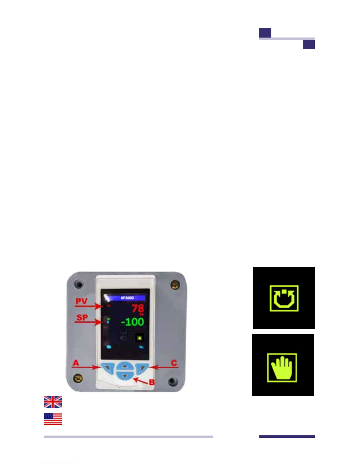
6.2 Verify controller is in AUTO MODE (check for Auto Control Mode Icon
in lower right section of the display screen). If in MANUAL, press the right
button (C) on the controller to place in AUTO MODE.
6.3 Adjust the AF3000 as follows
1. Press the left button (A) key to access the operator menu.
2. Press the down button (B) to enter CONFIGURE MODE.
3. Select by pressing the right button (C).
4. Press the down button (B) until BASIC is highlighted.
5. Press the right button (C) to select BASIC.
6. You should see the BASIC SETUP.
7. Press the right button (C) to enter BASIC SETUP.
8. Press the down button (B) until LOOP 1 SETPOINTS.
9. Press the right button (C) to enter LOCAL SETPOINT 1 sub
section.
OPERATING INSTRUCTIONS
Continued
Page 7
PAGE 7
HFT PIPESTOPPERS
®
10. Press the right button (C) to access the PROGRAM MODE.
11. Enter your desired setpoint following the on-screen prompts.
12. Press the right button (C) to select OK and lock your settings.
13. Press the left button (A) key to return to the section menu.
14. Press the down button (B) until LOOP 1 CONTROL.
15. Select by pressing the right button (C).
16. Select the ON/OFF HYSTERESIS with the right button (C)
and enter the number (5 deg. For F, 3 deg. For C)
17. Press the left button (A) key to return to the section menu.
*DO NOT ENTER THE LOOP 1 TIME PROP OR ALARMS OFF SECTION. IF
ANY CHANGES ARE MADE CONTACT FACTORY*
18. Press the left button (A) key until you see the OPERATOR
LEVEL screen.
19. The PV and SP should be displayed.
20. Verify the controller is in AUTO MODE if not repeat section
OPERATING INSTRUCTIONS
Continued
Auto Mode
Icon
Manual Mode
Icon
Page 8

PAGE 8
HFT PIPESTOPPERS
®
6.4 Adjust AF 3000 temperature reading by following the above process
except select LVL 3 and depress the lower right push button until the
readout displays O.AdJ. Use the up or down arrows to offset the display
reading to correspond to the reading indicated on the temperature monitor (this sets the controller temperature at the surface temperature of the
pipe as indicated on the temperature monitor at the start of the freeze).
Press lower right push button once more to return to process and control
temperature readout as described above.
6.5 Adjust control set point (lower display temperature readout using
the up/down arrow switches on the controller face to desired freeze seal
control set point. A control temperature of -34˚C (-30˚F) for carbon steel
pipe and -62˚C (-80˚F) for StainlessSteel pipe is recommended. The
control temperature maybe set colder to compensate for high ambient
conditions or high system heat conditions. If colder temperatures are used
the controller should be returned to these recommended temperatures
after the plug is established.
7. Initiate Freeze Seal
7.1 Open LN2 tank liquid valve.
7.2 Open the control solenoid header isolation valve, observe LN2 Flow
and freeze seal formation. LN2 ow is indicated by the sound of escaping
nitrogen gas and observing condensation at the coil exhaust.
OPERATING INSTRUCTIONS
Continued
Page 9

PAGE 9
HFT PIPESTOPPERS
®
8. Perform desired maintenance
8.1 The Accu-Freeze equipment should be monitored for proper and
continuous operation while system repairs are being performed.
9. Terminate Freeze Seal
9.1 The freeze seal can be thawed in a controlled manner if desired by
raising the AF 3000 set point to allow for thermal soaking of the pipe.
9.2 If thermal soaking is not required close the control solenoid header
isolation valve and the LN2 tank liquid valve.
9.3 The freeze seal can continue to be monitored using the temperature
monitor until seal has moved or the pipe has returned to baseline
temperature (COB Industries,Inc. recommends continued monitoring
until all thermocouples indicate it is safe to touch the freeze area with
bare hands and the freeze plug has thawed before restarting system
equipment).
9.4 After the freeze has warmed sufciently, disassemble the Freeze
wrap, and Accu-Freeze equipment.
10. Additional Information
10.1 The Accu-Freeze kit includes additional type T Thermocouple wire
and connectors.
OPERATING INSTRUCTIONS
Continued
Page 10

PAGE 10
HFT PIPESTOPPERS
®
Thermocouples can be made by cutting the wire to the desires lenght and
connecting one end to a male or female connector (as appropriate). The
copper colorered thermocouple wire should be connected to the copper
colored connector (also marked +) and the light colored wire connected
to the light connector (marked -). The other end should be stripped bare,
approximately 1inch and the two wires twisted tightly togehter to form
the thermocouple junction.
10.2 Connectors may be put on both ends of the thermocouple wire,
observing connection polarity, to form thermocouple extensions if the
monitoring and control equipment is placed away from the freeze area.
Table 1 Recommended Pipe Size Wrapping Table
*These are estimated times only, actual eld tests have not been
performed.
OPERATING INSTRUCTIONS
Continued
Pipe Size Copper Tube Wrap
Lenght
Time -
Hrs./Mins
1/4 through 3/4” 3” 0:10
1” 6” 0:18
1 1/2” 6” 0:25
2” 8” 0:40
3” 8” 1:20
4” 12” 2:15
6” 18” 3:40
8” 24” 5:30*
10” 36” 8:30*
12” 36” 12:30
Page 11
PAGE 11
HFT PIPESTOPPERS
®
COB Industries, Inc. recommends 1/4" copper tubing for all freeze wraps
up to and including wraps on 6" diameter pipe. 5/16" copper tubing
should be used for all freeze wraps on 8" diameter pipe and larger and
may be used for all freeze seal wraps.
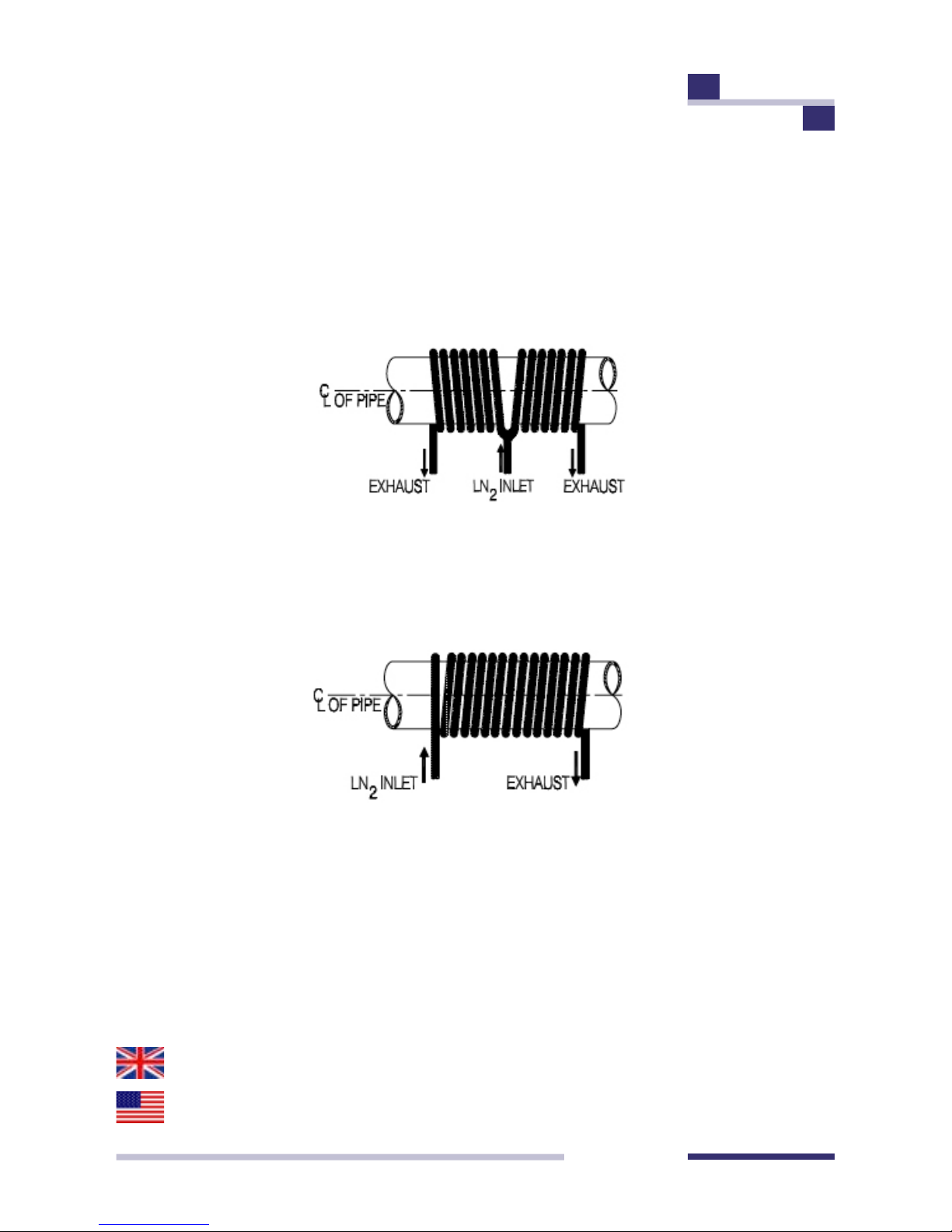
This coil conguration should be used on 6 inch diameter pipe and smaller.
See step 4.1 for coil placement.
This coil conguration should be used on 6 inch diameter pipe and
larger. See step 4.1 for coil placement. When this conguration is used
care should be taken to assure equal length of the coils from the tee to
exhaust to allow balanced LN2 ow in both legs of the coil.
OPERATING INSTRUCTIONS
Continued
Page 12
PAGE 12
HFT PIPESTOPPERS
®
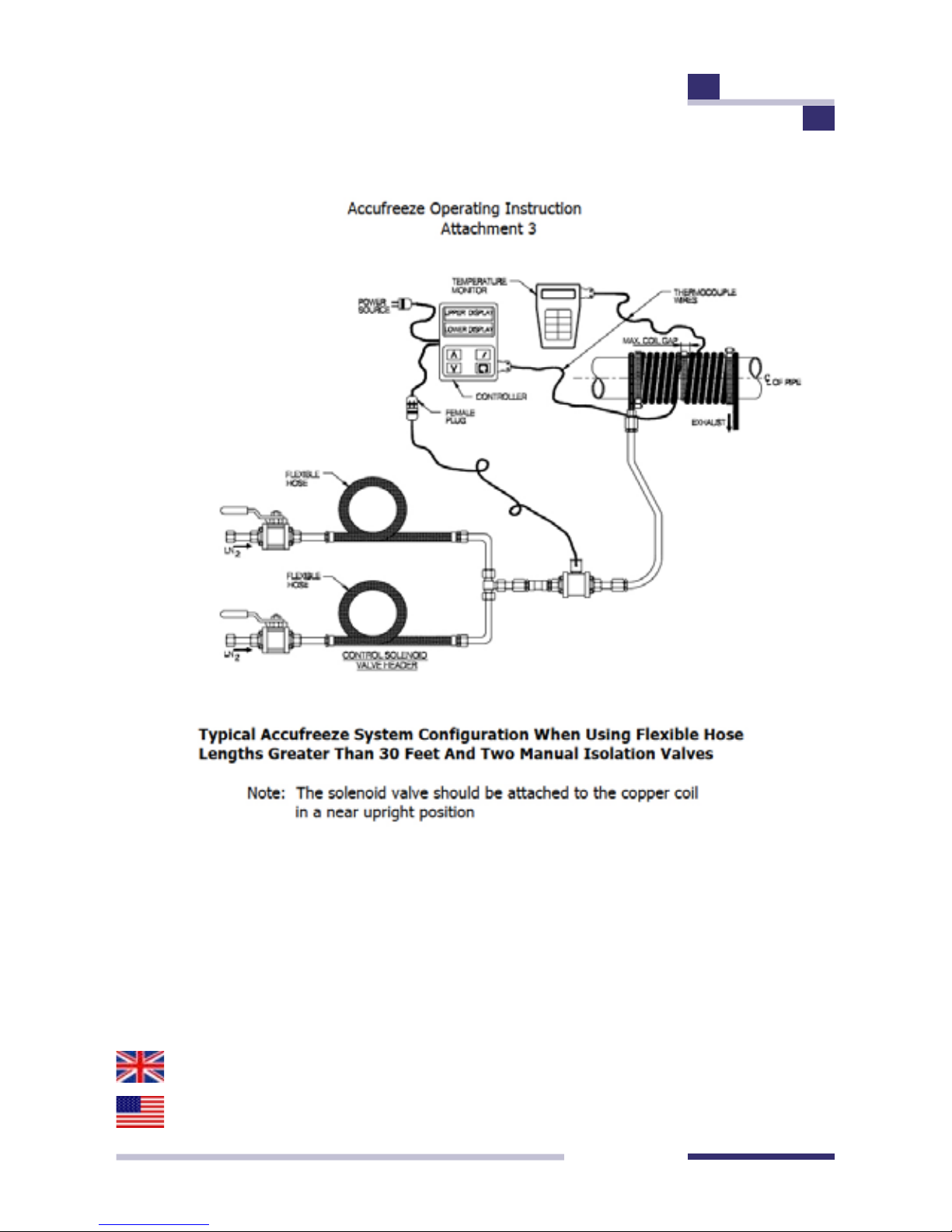
Typical Accu-Freeze System Conguration When Using
Flexible Hose Lengths Greater Than 30 Feet.
Note: the solenoid valve should be attached to the copper coil in a
near upright position
OPERATING INSTRUCTIONS
Continued
Page 13
PAGE 13
HFT PIPESTOPPERS
®
OPERATING INSTRUCTIONS
Continued
Page 14

PAGE 14
HFT PIPESTOPPERS
®
Table 2
LN2 Operating Pressure Recommendations
Single freezes up to 4 inch diameter pipe 22 Psi
Single freezes >4 inch to 8 inch diameter pipe 35 Psi
Single freezes >8 inch diameter pipe 35 Psi
Double freezes 3 inch to 6 inch diameter 35 psi
Double freezes > 6 inch diameter pipe 35 Psi
Feezes where distance from LN2 source to freeze wrap is >
20 feet and < 50 feet
35 Psi
Freezes > 50 feet and < 100 feet 35 Psi
Freezes > 100 feet from LN2 source to feet wrap are not
recommended with supplied system. Additional equipment
is recommend.
Contact
Vendor
OPERATING INSTRUCTIONS
Continued
Page 15
PAGE 15
HFT PIPESTOPPERS
®
HFT Pipestoppers
®
Product Range
© HFT
®
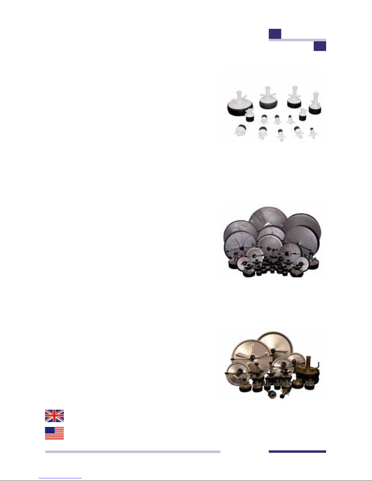
HFT Pipestoppers® Nylon Pipe Plugs
are suitable for a myriad of applications.
They are mostly used for weld testing,
leak testing of pipework fabrications, weld
purging or simply stopping to prevent
the ingress of dirt, rodents and other
unwanted material. These plugs will
provide airtight seals and in tests with
plastic pipes they are capable of sealing
against pressures from 60 Psi - 4 bar, to
over 100 Psi - 7 bar.
HFT® manufactures a large range of
Aluminium Plugs, suitable plugs for leak
testing and isolation, to compliment the
range of small diameter Nylon Plugs.
All natural rubber rings can be replaced
with silicone, nitrile, neoprene or viton
for chemical and temperature resistance.
Steel Expanding Single & Double
Plugs for increased stability and higher
pressure duties. For pressure testing and
stopping all pipework from 1.5 inch (38
mm) upwards. The test pressure capability
of the single stoppers is limited and the
double versions increase that capability,
while offering a greater stability in the
pipe.
Page 16
PAGE 16
HFT PIPESTOPPERS
®
HFT Pipestoppers
®
Product Range continued
© HFT
®
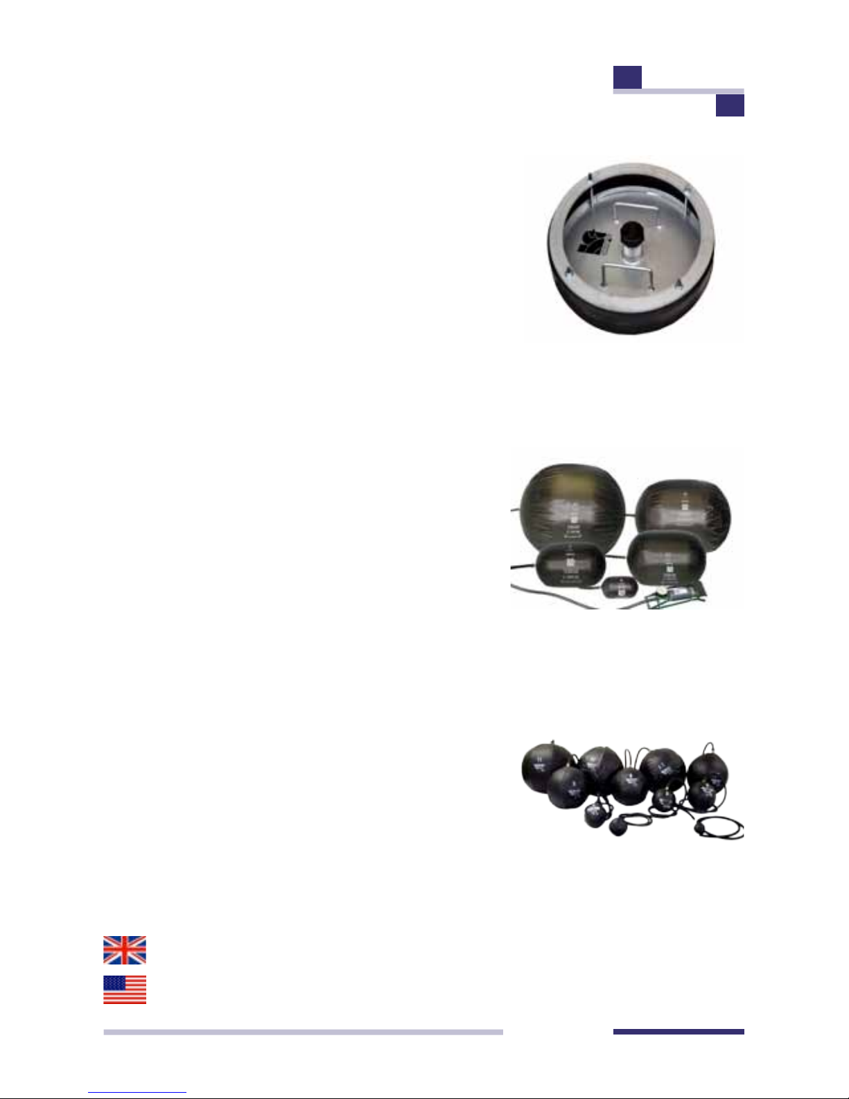
Rim Fastening Steel Plugs, single and
double port, for pressure testing and
stopping all pipework from 17" (432 mm)
up to 95" (2400 mm). Rim Fastening
Steel Plugs, especially the large sizes,
have the advantage over centre locking
plugs, that the nuts enable plates to be
closed together evenly with ease and
even seal in pipes that have slight out of
roundness.
HFT Pipestoppers® Inatable Stoppers
and Test Plugs, an easy way to stop the
ow of gas or liquid along a pipe or duct,
for collection of debris and to prevent
ingress of unwanted material or animals.
All Inatable Stoppers are manufactured
with a strong internal inatable bag made
to the required shape and covered in
waterproof sewn polyurethane coated
nylon for low friction and to prevent the
production of static electricity or accidental
sparking. The Inatable Stoppers range
includes; Spherical, Cylindrical, Heat
Resistant and the Specials.
Page 17

PAGE 17
HFT PIPESTOPPERS
®
Otros idiomas son actualmente en progreso. Para ahora, contacta
por favor su Distribuidor local
Andere Sprachen sind momentan im Gange. Kontaktieren Sie
vorläug, bitte Ihren örtlichen Verteiler
Les autres langues sont actuellement dans le progrès. Pour le
moment, s’il vous plaît contacter votre Distributeur local
Other LANGUAGES in PROGRESS
Page 18

PAGE 18
HFT PIPESTOPPERS
®
For further information and support, please contact us at:
Worldwide Ofces, Partners and Distributors are listed on our website
or contact us and we will direct you to the correct location
CUSTOMER SUPPORT and
WORLDWIDE CARE
Page 19

PAGE 19
HFT PIPESTOPPERS
®
All products are thoroughly tested to our Quality Control Procedures
prior to leaving our manufacturing facility. Should you encounter
a problem with your product, please notify us immediately upon
receipt.
Huntingdon Fusion Techniques HFT
®
warrants this product to be
free of defects in workmanship and material, with exceptions stated
below.
Warranty applies for normal and intended use of the product.
Huntingdon Fusion Techniques HFT
®
will not be held responsible
for any incorrect use of the product.
For further warranty information, please refer to our terms and
conditions.
All warranties shall not apply to any product or component which
has been repaired or altered by anyone other than Huntingdon
Fusion Techniques HFT
®
.
Huntingdon Fusion Techniques HFT
®
shall not be liable for indirect,
special, incidental or consequential damage or penalties and does
not assume any liability of Purchaser, or to others, for injury to
persons or property.
This warranty is in lieu of all other warranties, expressed and implied.
E&OE
WARRANTY
Page 20

ACCU-FREEZE UI A5 AF91 - 26-04-2018 ME
HFT Pipestoppers® a division of Huntingdon Fusion Techniques HFT
®
Stukeley Meadow Burry Port Carms SA16 0BU United Kingdom (UK)
Telephone +44 (0) 1554 836 836 Fax: +44 (0) 1554 836 837
Email [email protected] or [email protected]
www.pipestoppers.net www.huntingdonfusion.com
Copyright © HFT®. All rights reserved. This publication may not be reproduced by any means without the written permission
of Huntingdon Fusion Techniques HFT
®
HUNTINGDON FUSION
TECHNIQUES
HFT
© HFT
®
 Loading...