

Page 1
hf sensor GmbH
Weißenfelser Straße 67
D-04229 Leipzig
phone: +49.341.49726-0
fax: +49.341.49726-22
email: [email protected]
http://www.hf-sensor.de
MOIST 350 B
Operation Manual
Page 2
2
Content
1 Construction 3
1.1 Basic equipment and accessories supplied 3
1.2 Interconnection sockets 7
1.3 Keyboard layout 8
2 Initial operation 9
2.1 Power supply 9
2.2 Power up 9
2.3 Download to personal computer 10
3 Menu tree Moist 350 11
4 Handling 12
4.1 Screen elements 12
4.2 Menu items 12
5 Technical data 23
6 Measurements with the meter 24
6.1 Basics of Dielectric Moisture Measurements 24
6.2 Microwave Moisture Measurements 25
6.3 MOIST-Method and it’s special features 26
7 Applications 32
8 Scope of delivery 33
9 Safety Instructions 34
10 Installation instruction for USB-driver unit 35
Page 3
3
The handheld microwave moisture meter MOIST 350 B was designed for nondestructive moisture measurements in various building materials. In its basic
configuration it consists of a microcontroller based handheld with colour display and
sensing heads. More moisture probes, a RH humidity probe, a penetration applicator
MOIST-ENDO and software MOISTANALYZE are available optionally.
1 Construction
1.1 Basic equipment and accessories supplied
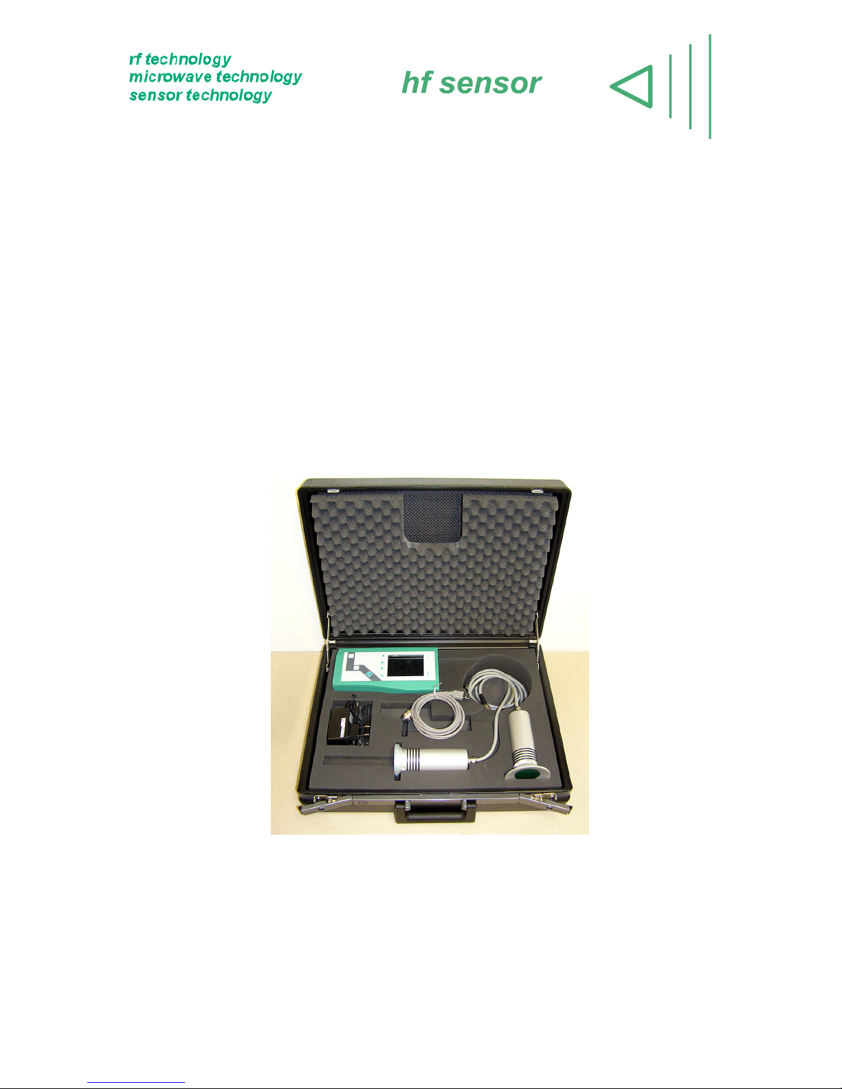
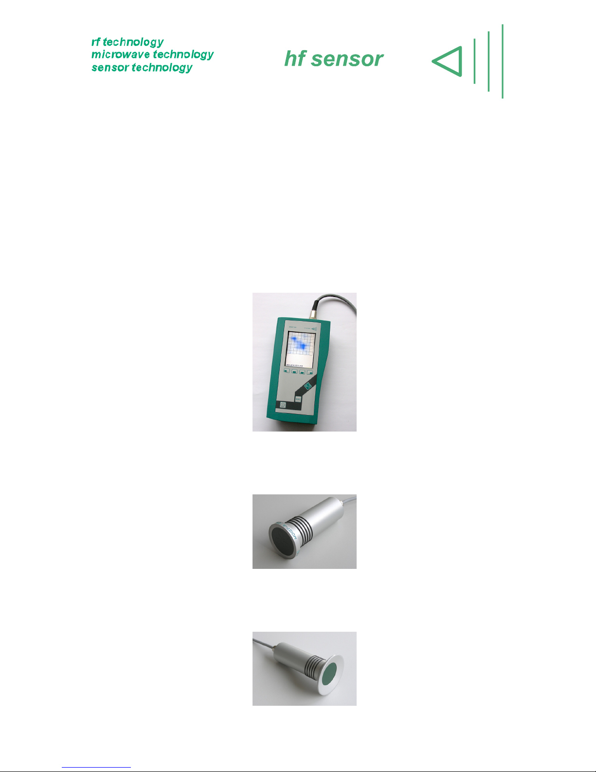
Basic equipment of the meter consists of
the handheld MOIST 350
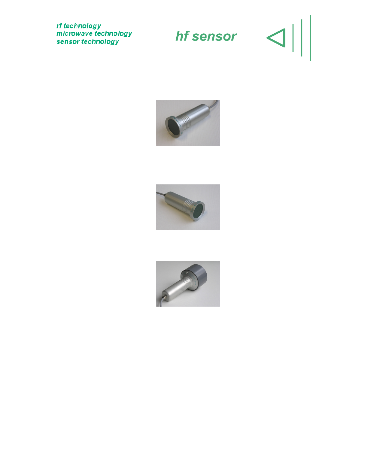
the surface sensing head MOIST-R1M V2 (sensing head with narrow rim and
penetration depth up to 3 cm)
the volume sensing head MOIST-PM V2 (sensing head with plate rim and
penetration depth up to 30 cm)
Page 4
4
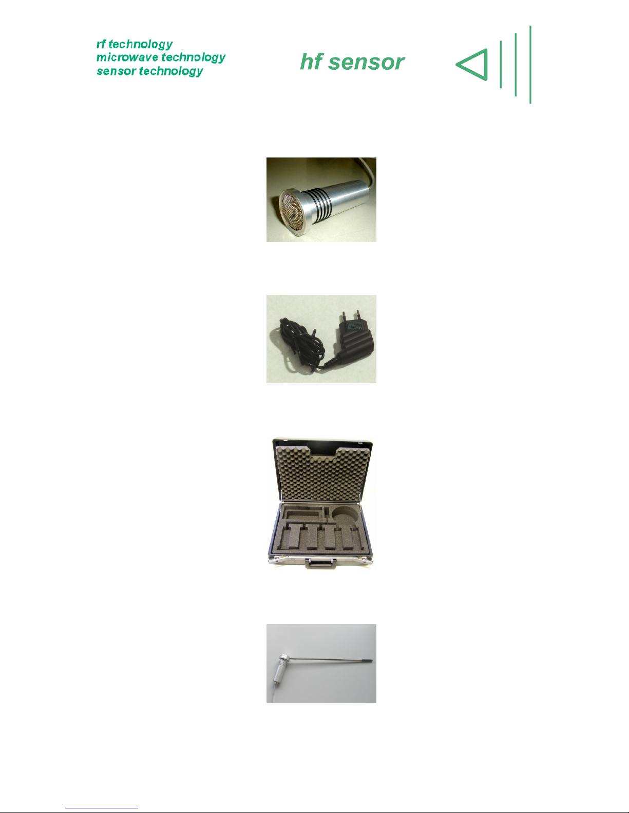
the RH humidity probe
power supply (with battery charging circuitry integrated in the handheld)
carrying case
penetration applicator MOIST-ENDO M
Page 5
5
the sensing head MOIST-R2M V2 (with penetration depth up to 7 cm into the
material)
the sensing head MOIST-DM V2 (with penetration depth up to 11 cm into the
material)
the sensing head MOIST-SM (with penetration depth up to 80 cm into the material)
Page 6
6
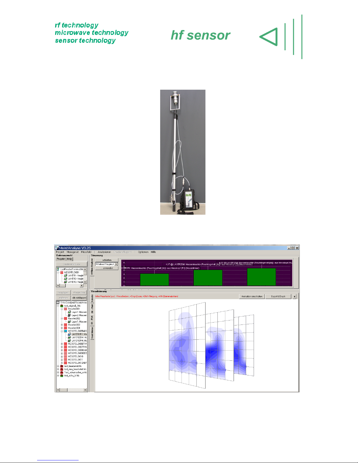
Telescopic lengthening MOIST TELE1 for measurements with MOIST microwave
probes at floors or ceilings
software MOISTANALYZE for data transfer and graphical visualisation (including
interface cable)
Page 7
7
1.2 Interconnection sockets
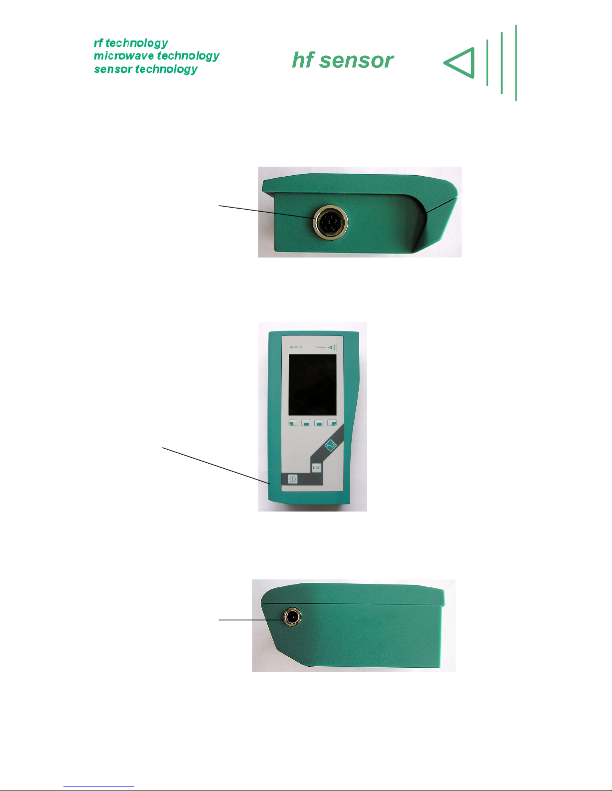
At the upper side of the handheld is the socket for the sensing heads (7 pins).
Sensing head socket
[S]
Figure 1: MOIST 350 upper front side
The serial interface socket USB (4 pins), is located at the left side of the handheld.
USB [U]
At its lower front side the meter has a socket for connecting the external power supply.
Operating the meter is also possible when using the power supply. Please turn off the
moisture meter before you plug in the power supply.
Power supply socket
Figure 2: MOIST 350 lower front side
Page 8
8
Warning: The included accumulator is not designated to be changed by the end
user. If the accumulator can not be charged anymore (after app. 1000 cycles) you
have to send the handheld to hf sensor.
1.3 Keyboard layout
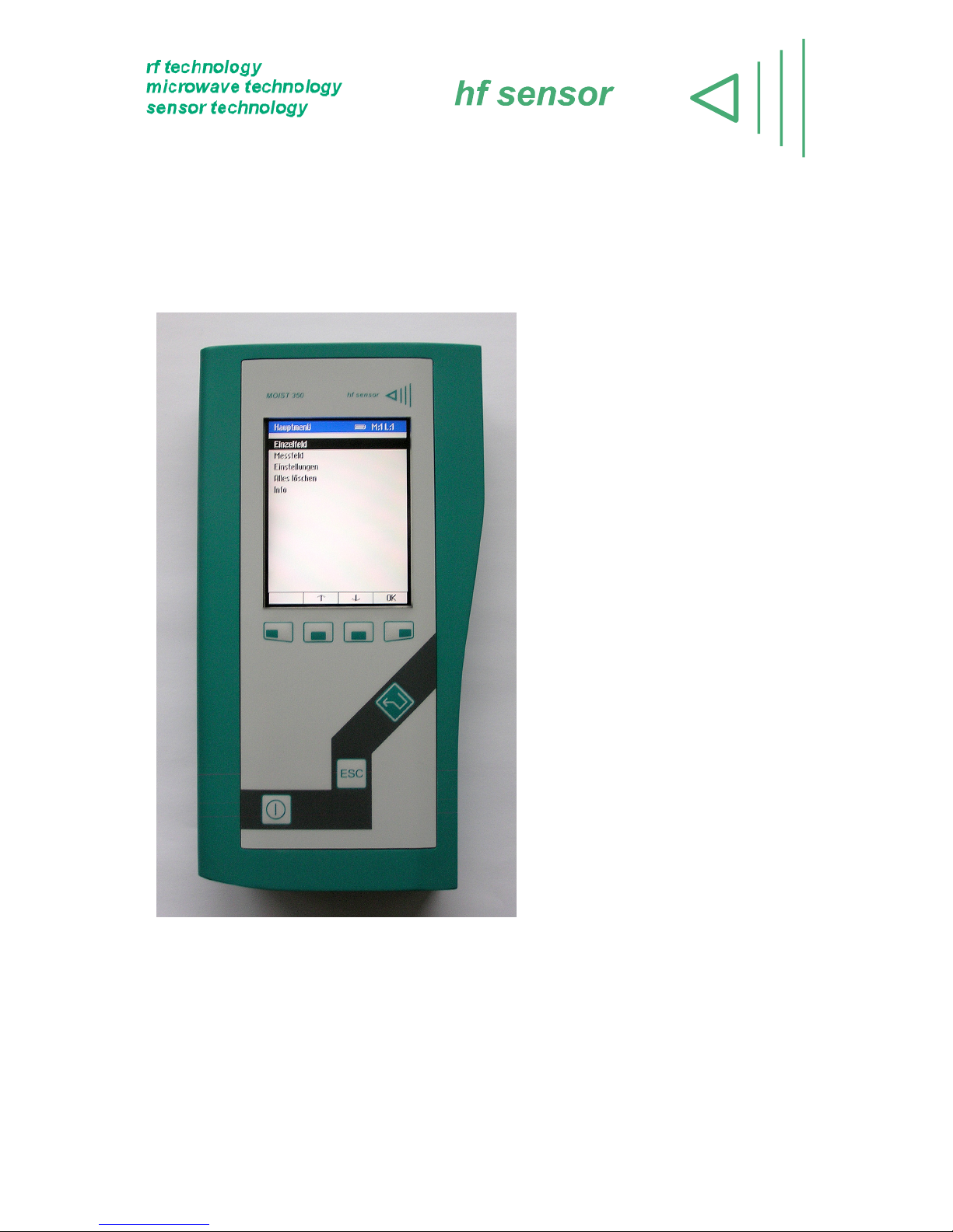
(1) <ON/OFF>-Button: Turns the
device on/off.
(2) Softkey-Buttons: The function
changes depending on the
menu item. The actual function is
shown on the bottom bar.
(3) <ENTER>-Button: Starts the
measurement. Alternatively it can
be used as right softkey.
(4) <ESC>-Button: To quit the input
of layer or array names.
Alternatively it can be used as left
softkey.
Figure 3: Keyboard layout
(1)
(4)
(3)
(2)
Page 9
9
2 Initial operation
2.1 Power supply
The device is designed to be used with the enclosed power supply as well as the
included accumulator for independent operation.
Please turn off the device before you plug in the power supply.
The charge indicator is calibrated for the original accumulator. The use of other types of
accumulator can destroy the device but at least causes wrong information about the
charge state.
The use of non rechargeable batteries is forbidden. These batteries could destroy
the device or cause fire.
The recharging process starts automatically when the power supply is connected. This
procedure takes up to 4 hours (depending on the charge state).
2.2 Power up
The sensor head must be plugged in at the socket [S] (7 Pins).
Before you can change the sensor heads you have to turn off the device.
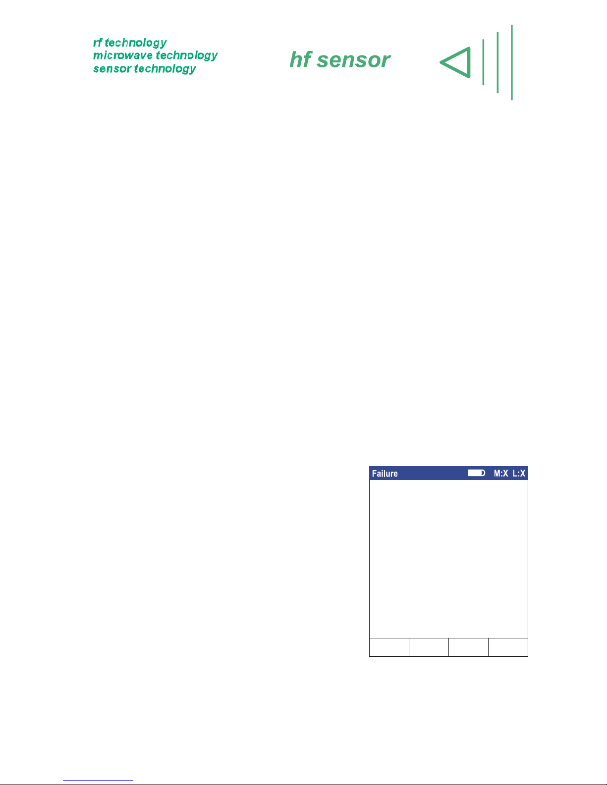
The sensor head type is detected automatically. If the
communication with the head fails an error message
occurs.
Figure 4 – Failure report
Wrong sensorhead:
Used sensorhead 30XXX
Neded sensorhead 30XXX
OK
Messen
Page 10
10
Mostly no sensor head is connected or the head has been changed during the on-state
of the device. A reset of the handheld (turn off and on) will relieve the failure.
The handheld will be turned on by pressing the button <ON/OFF>.
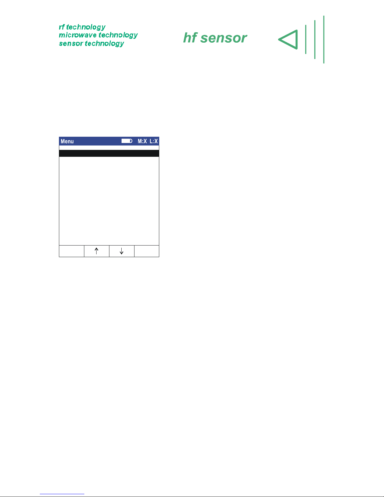
Depending on the mode the main menu will be displayed or the screen for download to
PC. The modes toggle according to the plugged in USB-cable.
Figure 5 - Main menu
During power up the device searches for a valid sensor head. This procedure can take
a few seconds (depending on the sensor type).
2.3 Download to personal computer
The enclosed USB-cable should be plugged in the socket [U]
If this cable is connected to the PC before you power up the device it will be started in
download mode. In this mode no further actions are necessary. The stored data can be
downloaded to the PC with the software MOISTANALYZE. During this mode the
shutdown function is disabled. The device has to be shut down manually after finishing
the download. It is recommended to run the handheld with the enclosed power supply.
Measurement array
Preferences
Delete all
Info
OK
Single array
Page 11
11
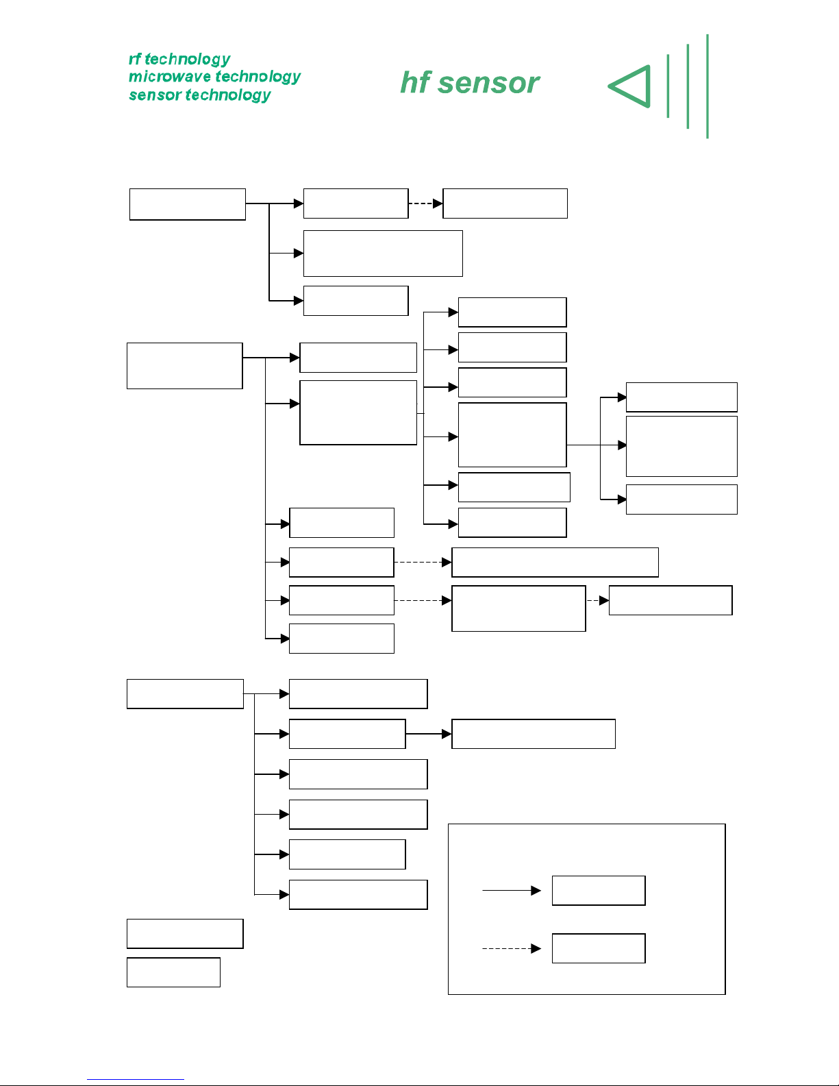
3 Menu tree Moist 350
4
Single Array Measure
Delete
Show measurement
value
Select material
Info
Delete all
Legend
Selection
Sequence
Keyboard beep
Preferences Averaging …
Display off after
Set date Year/Month etc.
Device off after
Brightness
Manually
Auto
From
calibration
curve
Measure Measurement
array
Show
measurement
value
Select Measurement array / Layer
New Measurement
array / Layer …
Select material
Delete
Edit note
Value
Graphic
Statistics
Set
indicating
range
Colour profile
Grid …
Page 12
12
4 Handling
4.1 Screen elements
4.1.1 Status bar (upper end)
The status bar shows important information about the state of the device, e. g. the accu
state.
In mains operation the accumulator symbol changes to a mains plug.
On the right side you can see the selected measurement array (M) and the selected
layer (L). In the single array mode you can see the letters SA. If an invalid
measurement array or layer is chosen “⎯“ occurs.
4.1.2 Control bar (bottom end)
For controlling the functions of the device four softkeys are used. These keys change
their functions depending on the menu item. During the most functions the <ENTER>
button can be used as right softkey alternatively, just as the <ESC> button alternatively
to the left softkey.
The <ENTER> key is generally used to trigger the measurement process, and to
confirm the settings of the array name or layer name. The input of the array name or
layer name can also be acknowledged with <ESC>.
4.2 Menu items
4.2.1 Menu item single array
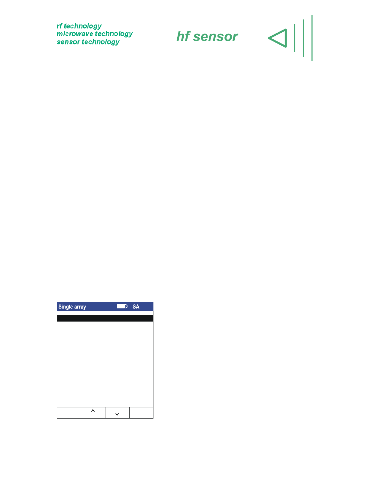
In a single array independent measurement values
are collected together in a row. To store one value
you have to press <save>. This option is usefull, if
you want to record single (indepentend)
measurement points without creating a picture of the
moisture distribution. Because in this mode no local
relations are available the plot of the graphic is never
possible.
Figure 6 – Menu item single array
Show measurement value
Delete
OKEscape
Measure
Page 13
13
4.2.1.1 Measure (single array)
If you choose this item you can see a list of the available materials in the installed
sensor head. After the selection of the material the measurement screen opens.
Pushing <ENTER> starts the measurement and displays the result. If you have selected
multiple measurement cycles to calculate a mean value, you have to press <ENTER>
several times according to the cycle count. (Average value)
If the result is displayed you can store the value with its corresponding data like time
and material by pressing <SAVE>. If you didn’t press this key and a new measurement
has been started by pressing <ENTER> the current value will be lost.
To return to the menu item single array please press the button <ESCAPE>.
4.2.1.2 Show measurement value (single array)
With this item you can display stored single entries likewise a card file. Any
measurement value will be displayed with the corresponding material and the time
stamp.
4.2.1.3 Delete (single array)
Selecting this menu item will erase the single array after a safety check without erasing
the measurement arrays.
Page 14
14
4.2.2 Menu item measurement array
When selecting this item you can record measurement values in measurement arrays.
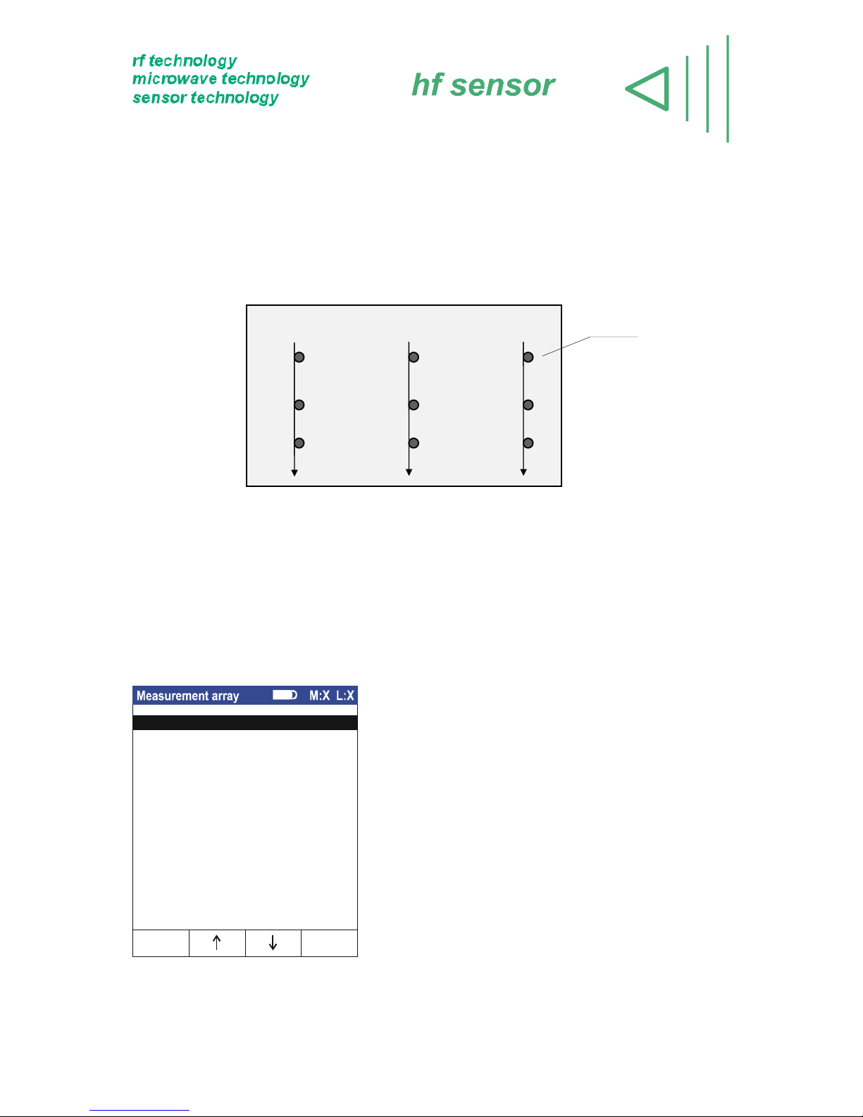
Measurement arrays are spreadsheets of measurement values, where the values
are recorded straight in columns from top to bottom and column-wise from left to
right.
Figure 7: Recording of values at a damp wall
This way to record values brings advantages for all applications, in which you want to
see the distribution of moisture in an area, e.g. the moisture distribution in a damp wall.
The measurement points should be picked up in the same manner as they will be
stored. A suggestion for such a measurement grid shows figure 7 (MP = Measurement
point).
Within a measurement array there are eight Layers
possible. Hence it is possible to measure the same
area with different sensor heads. Depending on the
character of the head you can measure in different
depths. In the software MOISTANALYZE you can plot
these layers.
Figure 8 – Menu item measurement array
damp wall
Column 3Column 2
Culumn 1
MP 1 MP 1
MP 1
MP 2MP 2
MP 2
MP 3MP 3
MP 3
Show measurement value
Edit note
Select
New
OKEscape
Measure
Delete
Page 15
15
4.2.2.1 Measure (measurement array)
In this menu you can measure within the previously created and selected measurement
array. Pushing the button <ENTER> starts the measurement. Depending on the value in
preferences item “average” the end value will be displayed only after repeatedly pushing
the <ENTER>-Button. (Default setting for averaging = 1)
The displayed value will be stored automatically and the next coordinate will be given.
Below the measurement value you can see the coordinate of the next measurement in
the grid (row-column).
With the help oft the key <PROCEED> you can add a void measurement point, e. g. to
exclude a smokestack or a window. The measurement grid will be counted one step
ahead.
With pushing the key <N.column> you can add a new column in the grid.
The button <UNDO> erases an already stored measurement point. The grid will be
counted one step back (with maybe taking back a column).
<ESCAPE> returns to the menu item measurement array.
4.2.2.2 Show measurement value (measurement array)
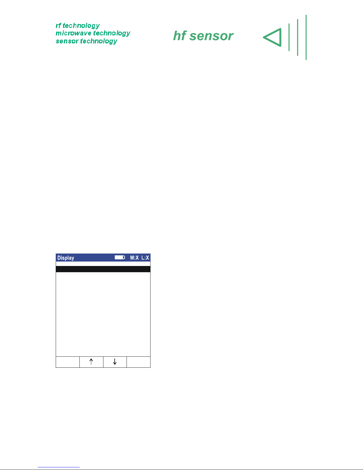
Measurement arrays are capable to be displayed as
single values likewise index cards (Menu item Value)
as well as a graphic (Menu item Graphic). Condition
to display an array as graphic is the existence of at
least two columns and two rows. The graphic size is
adjusted automatically.
Figure 9 – Menu item show measurement value (measurement array)
1. Value
Here, the single measurement points are displayed like a card index.
Graphic
Statistics
Set indicating range
Colour profile
OKEscape
Value
Grid ...
Page 16
16
2. Graphic
Here, the measurement points are graphically visualized as grid humidity graphics.
Press repeatedly any key (except the <ON/OFF> or <ESCAPE> button) and the
statistical parameters of the measuring array are displayed in the bottom of the screen.
The <ESCAPE> button returns to the menu item Show measurement array.
The statistic parameters are displayed only when the "Grid" is enabled.
The measuring array must have at least two columns and two rows to be displayed as a
graphic. The graphical visualization automatically adjusts to the size of the
measurement array. If the number of measuring points is greater than the number of
pixels of the display, a graphical visualization is only possible with the software
MOISTANALYZE.
3. Statistics
Important statistical values of the measuring field are shown here (average, standard
deviation, minimum, maximum).
If there are several equal minima or maxima in the measurement field, the location
information for the first found location applies.
The statistical values are also displayed in the graphic menu on the bottom of the
screen. (Menu item Graphic). To show the single statistical values press repeatedly
any key (except the <ESCAPE> button). To quit the graphic menu press the
<ESCAPE> button.
4. Set indicating range
To display the grid humidity graphics or the moisture distribution with the „false colour“
profile you can define the upper and the lower border of every layer. These borders will
be saved automatically. They will be available after restart and in the Software
MOISTANALYZE
• The <Auto> mode define the borders automatically by searching for the highest
and the lowest value of the measuring field.
• The <From calibration curve> mode define the borders automatically by taking
the given values of the calibration curve. This mode is the default.
• In the <Manually> mode you can define the borders manually.
Page 17
17
The borders are displayed on the bottom of the screen after loading the graphic. (Menu
item Graphic)
The Symbols
(A) Auto
(C) From calibration curve
(M) Manually
represent the selected indicating range.
The borders are displayed only when the "Grid" is enabled.
5. Colour profile
A colour profile for the display of a measurement array in "false colours” can be
selected here. These profiles correspond with the profiles in the software
MOISTANALYZE.
6. Grid
With this you can overlay a grid over the graphic. The intersection points show the
measurement points in the measurement area. The statistic values and the display
range are only displayed on the bottom of the screen if the “Grid” is activated.
4.2.2.3 Edit note
Every measuring field have text field where a shot note can be added. The text have a
maximum length of 24 characters. To edit the note use the following buttons:
Press the arrow buttons <
←> or <→> to select the character. To confirm the character
press the <ENTER> button.
To select a position of the cursor in the note press the < <Pos> button or <Pos> >
button.
The symbol
< in on the virtual keyboard is used as a backspace key to delete
inadvertently entered characters. Confirmation by <ENTER> button.
The symbol in the virtual keyboard is used to insert spaces in the note. Confirmation
by <ENTER> button.
The text is saved after pressing <ESC> button and can be edited later in the software
MOISTANALYZE. In the software, the limitation to 24 characters is repealed.
Page 18

18
4.2.2.4 Select (Measuring field)
Select a measuring field and then the layer to display the results as a graphic.
4.2.2.5 New (Measuring field)
To measure an object, a measurement field have be created with at least one
layer.
In this menu a measuring field with an associated layer can be created. A existing
measuring field can also be supplemented by a additional layer here.
The sensor must be connected to create or supplement a new layer for the
measurement field. This layer later must always be measured with the measuring head,
which was used at the time the layer was created. Otherwise, the error window "Wrong
sensorhead" appears.
1. Input of measurement array name or layer name
At the beginning a default name appears, e. g. “MEAS ARRAYnnn” or “LAYERnnn”,
with nnn being a serial number. This name can be accepted or can be adapted to your
own wishes.
The text have a maximum length of 24 characters. To edit the name use the following
buttons:
Press the arrow buttons <←> or <→> to select the character. To confirm the character
press the <ENTER> button.
To select a position of the cursor in the note press the < <Pos> button or <Pos> >
button.
The symbol
< in on the virtual keyboard is used as a backspace key to delete
inadvertently entered characters. Confirmation by <ENTER> button.
The symbol in the virtual keyboard is used to insert spaces in the note. Confirmation
by <ENTER> button.
The name is saved after pressing <ESC> button and can be edited later in the software
MOISTANALYZE.
2. Select material
Here you can select the material from a list.
Page 19
19
4.2.2.6 Delete (measurement array)
After a safety check you can erase one separate measurement array with all its
belonging layers. Other measurement arrays or the single array are left unchanged.
Attention: Measuring arrays that were deleted from the device, can not be
recovered!
Page 20
20
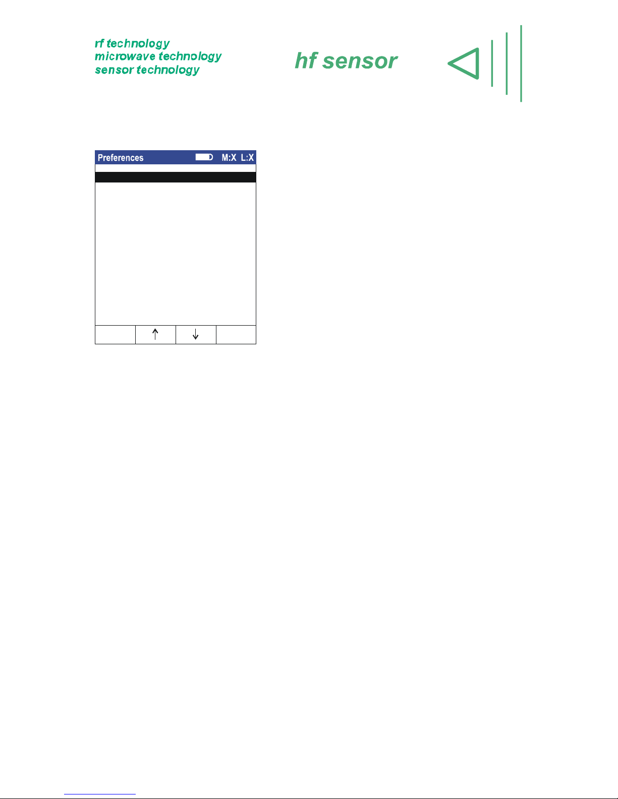
4.2.3 Menu item Preferences
All chosen preferences are stored non volatile.
Figure 10 – Menu item preferences
4.2.3.1 Averaging (setting)
Depending on the material it is sometimes useful to determine an arithmetic mean. In
this setting you can choose how many single cycles are needed to determine one value.
Up to 15 single measurements can be gathered to accumulate a measurement value.
(default setting = 1)
4.2.3.2 Set date (set real time clock)
To date the measurements with time stamps a real time clock is included. In the sub
items you can change the year, month, date, day, hour and minute. Press the
<ESCAPE> button to return to the menu item Preferences. At the same time the
changes are accepted.
The coin cell to buffer the clock is independent to the NiMH-accumulator of the device. If
the clock drops the settings, the coin cell is low and has to be changed by the
manufacturer.
An exchange by the customer is forbidden and voids the guaranty!
Also a loss of measurement data indicates an exhausted coin cell. The cell has an
average lifetime of app. 4-5 years.
Set Date
Keyboardbeep
Device off after
Brightness
Display off after
OKEscape
Averaging ...
Page 21
21
4.2.3.3 Keyboard beep (set)
You can set the keyboard beep on or off.
4.2.3.4 Device off after
To expand the operation time you can set the time before the whole device is shut down
automatically. The possible value ranges from 1 minute to 5 minutes. If you choose “Off”
the device can only be shut down by using the button <ON/OFF>. Setting the value to
Off disables also “Display off after”.
The settings are not significant for the mode download to PC!
4.2.3.5 Brightness
Here you can change the brightness of the TFT-display in steps from 10 to 100 percent.
This value affects the operating time. 50 percent is the default value.
4.2.3.6 Display off after
To expand the operation time you can set the time before the display is turned off. The
possible values ranges from 15 to 60 seconds and off. To turn the display on again you
can press any button (except <ON/OFF>).
If this function is activated, the “shut down device after” value will be set to 5 minutes
automatically to prevent a low discharge. The settings are not significant for the mode
download to PC!
Page 22
22
4.2.4 Menu item delete all
Selecting this menu item will erase all data (measurement arrays, single arrays). This
operation can take a view seconds and is displayed by a progress bar.
4.2.5 Menu item info
This menu item shows the failure state from the handheld/sensorhead and the software
version.
4.2.6 Error indication
Indication Cause
Wrong sensor head after power up No sensor head plugged in
Wrong sensor head during operation
• The sensor head has been changed
without turning off the device.
• You try to measure a layer which was
created with another sensor head
• No sensor head plugged in
The real time clock fails Coin cell is low
The measurements are lost
Coin cell is low
The device is not be able to power up Accumulator is low
The device turns off unexpected Accumulator is low
Page 23
23
5 Technical data
Microcontroller based handheld Moist 350 B with 3,5“ colour display
Power supply: 4 x 1,2V (AA - NiMH-accu) or
mains operation with power supply
Please turn off the device before plugging in the power
supply.
Capacity of accu: 2.000 mAh
Operating time: 8 hours (stand by) by NiMH-accumulator or
4 hours continuous operation
Charge time: app. 4 hours
Dimension: Handheld 195 x 95 x 40 mm
Head MOIST-R1M V2 130 x 50 mm
Head MOIST-PM V2 130 x 50 mm (funnel D=80 mm)
Interface PC: USB
Display: 3,5’’-TFT-colour display (QVGA 320 x 240 pixels)
Internal memory: 128 measurement arrays with 8 layers
per layer app. 32.000 values
128 single arrays (single values)
Page 24
24
6 Measurements with the meter
The basic configuration of the MOIST 350 consists of the handheld and the sensing
heads MOIST-PM V2 and MOIST-R1M V2(see title).
For doing measurements some special features of the microwave method have to be
kept in mind, which are described in the following chapter.
6.1 Basics of Dielectric Moisture Measurements
The microwave method is a dielectric moisture measurement method.
Dielectric measurement methods are based on the special physical properties of water.
Water is a polar molecule, i.e. the molecule doesn’t appear electrically neutral when an
electric field is applied to it. That’s why the water molecule will orientate in a preferred
direction given by the electric field - it is polarizable. If an alternating electromagnetic
field is applied, then the water molecule will start rotating with the frequency of the field
(orientation polarization). This effect is described macroscopically by the physical
property Dielectric Constant or permittivity.
The dielectric effect of water is very strong, it’s permittivity is about 80. The permittivity
of the most solids (for instance building materials) is much smaller, it ranges between 2
and 10 and mainly between 3 and 6.
Therefore the difference between the permittivity of water and the permittivity of the
solids is measured. Because of the great difference of these values even small amounts
of water can be detected well.
Page 25
25
6.2 Microwave Moisture Measurements
When the frequency is rising (in the microwave region) the polarization of the water
molecule becomes more and more difficult because of internal binding forces (the water
molecule „swims“ in the water and is bound to the other molecules).
The microwave field causes an internal friction in the material, which can also be called
dielectric loss. If the power of the microwave radiation is large enough then the material
will be heated. This is the effect which is used in the kitchen microwave oven for heating
food.
Dielectric losses can be measured with special microwave arrangements. The
microwave power necessary for this is much lower than for heating purpose, it can
be < 1 mW. That’s why every kind of danger to human health (electrosmog) can be
excluded.
The maximum of dielectric losses of water corresponds to a frequency of about 20 GHz.
So one would prefer this frequency for getting the maximum measuring effect.
Unfortunately the wavelength of the electromagnetic wave is so small at this frequency,
that a measurement won’t be useful. Moreover dielectric losses are high enough at
lower frequencies too for getting a good detection of water.
So in the microwave region two effects can be used for moisture measurement: the high
permittivity of water (exactly: the real part of dielectric constant) and the dielectric losses
(exactly: the imaginary part of dielectric constant). In other words: The coupling of the
electric function of a microwave moisture meter to the physical properties of water is
very close.
Besides that the microwave frequency range has some more advantages: As can be
shown easily from the basic equations of electro-technics (Maxwell equations), the
influence of ohmic losses (ionic conductivities, e.g. salinity of a building) decreases
when the frequency is raising. Above 1 GHz ohmic losses are negligible compared with
dielectric losses. That means: Microwave moisture measurement is independent from
salinity.
In the preferred frequency range between 2 and 10 GHz the corresponding wavelengths
are within a range that makes it possible to design relatively good focusing applicators
as antennas or stray-field-sensors in a useful size.
Using these applicators penetration depths in the decimetre range can be achieved
because of the directivity of the antennas. By use of stray-field arrangements some
centimetres can be reached.
Conclusion: Microwave moisture measurement arrangements allow a non-destructive
comparison between the water content at the surface of a material and within its
volume.
Page 26
26
6.3 MOIST-Method and it’s special features
To transform the advantages of microwave moisture measurements described in the
previous chapter in a useful format, hf sensor developed two sensing heads, which are
only to be put onto the material: MOIST-R1M V2 as a surface sensing head and
MOIST-PM V2 as volume sensing head.
For measuring both sensing heads are put smoothly onto the material to be measured.
A good surface contact is very important. Using the procedure described in chapter 3 a
measurement can be realized in a few seconds.
6.3.1 Surface Moisture Measurement with MOIST-R1M V2
The surface sensing head MOIST-R1M V2 contains a stray field arrangement, which
enables a penetration depth of up to 3 cm. It is well suited for moisture measurements
in the layers of a material which are close to the surface. Measurement is realized on
the basis of a reflection principle, i.e. the part of a microwave is measured which is
reflected from the material dependent on its moisture content.
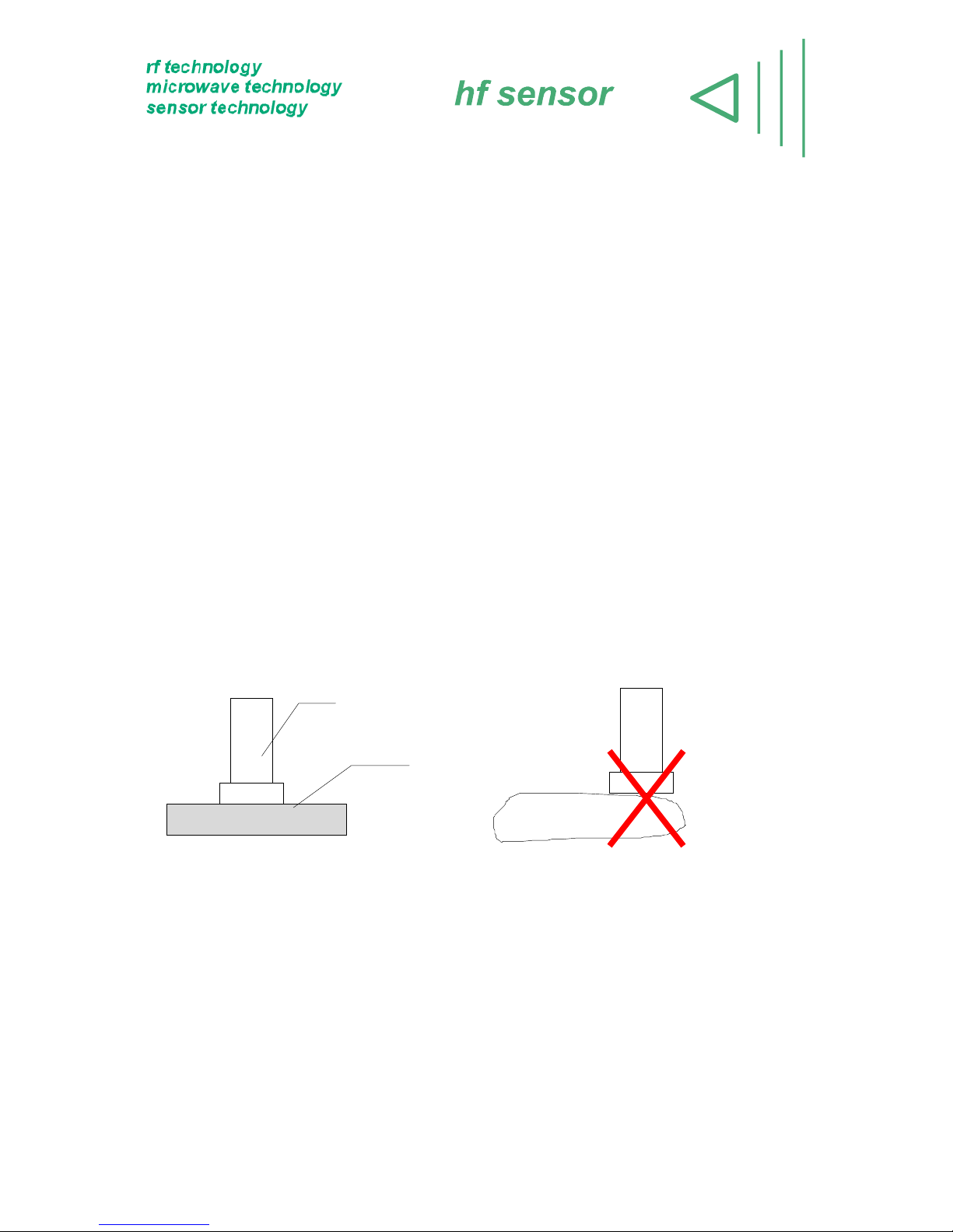
For realizing the measurement the sensing head has to be put smoothly onto a plain
surface of the material under test. In general care has to be taken that there are no
metallic objects below the test object.
Sensing head
Tested Object
Page 27
27
Surface Roughness and Tipping
Because of the small penetration depth surface roughness of the material has relatively
strong influence on the measured data. Surface roughness in the category of plaster or
floor isn’t a serious problem, but for a reliable measurement surface roughness
shouldn’t be larger.
The area, where the sensing head has to be put onto, shouldn’t have too large
roughness and ledges. It could be better if the measurement would be repeated at a
smoother place. If such smooth places aren’t available then a mean value should be
generated from several single measurements. By calculation of the standard deviation
the reliability of the measurement can be checked.
Take care during the measurement that the sensing head isn’t tipping. Even low
variations in the distance between the active microwave element and the surface of the
material, as they can be caused by tipping, may cause considerable falsification of the
measured values.
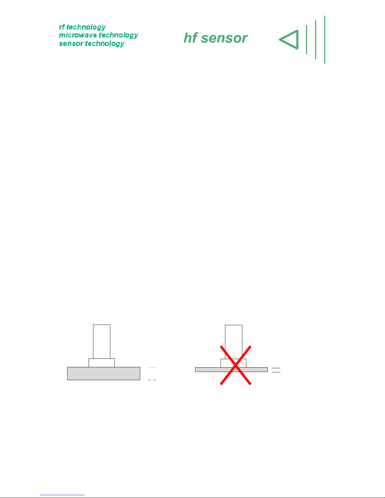
Minimum Thickness of Material
The field penetrates the material, depending on moisture and material type, in the range
of 1 ... 3 cm. Therefore test objects must have a minimum thickness in this range. If
material thickness is lower, the measurement can be falsified.
Moisture measurement with the surface sensing head MOIST-R1M V2 is also possible
in objects with lower thickness.
Before doing such a measurement hf sensor must be consulted, because usually
for such measurements special arrangements must be used.
> 1 ... 3 cm
< 1 cm
Page 28
28
Minimum Distance from lateral bounds
The microwave field of the surface sensing head MOIST-R1M V2 has some lateral
extent. Therefore a minimum distance from lateral bounds must be kept to avoid
falsification of the measurement.
The minimum distance from the lateral bounds of the test object is given by half
the diameter of the sensing head.
In principle moisture measurement with the surface sensing head MOIST-R1M V2 is
also possible when the distance to lateral bounds of the test object is lower.
Before doing such a measurement hf sensor must be consulted, because usually
for such measurements special arrangements must be used.
6.3.2 Moisture Measurement in the volume of the test object with sensing head
MOIST-PM V2
The volume sensing head MOIST-PM V2 contains an antenna arrangement, which
enables a penetration depth of up to 30 cm. It is well suited for moisture measurements
in the volume of the material. Measurement is realized on the basis of a reflection
principle, i.e. the part of a microwave is measured which is reflected from the material
dependent on its moisture content.
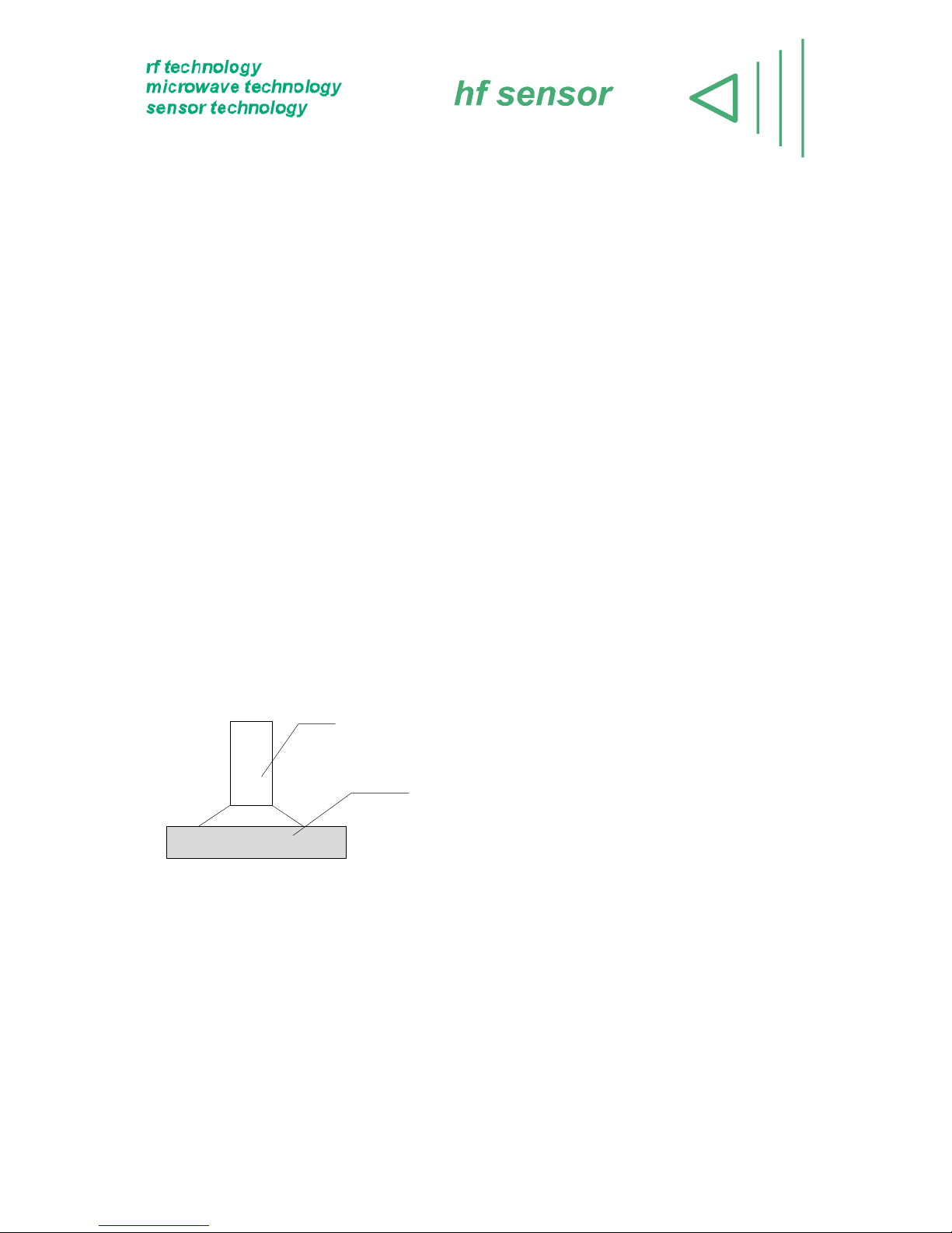
For realizing the measurement the sensing head has to be put smoothly onto a plain
surface of the material under test. Generally care has to be taken that there are no
metallic bodies under the test object.
The antenna arrangement transforms the electromagnetic wave oscillation generated in
the sensing head into an electromagnetic wave propagating into the test object.
Contributions to the reflection of this wave do not only come from the surface of the
material, but also from the deeper layers of the test object. The portions of the
contributions of the single volume elements decrease with increasing depth, but much
slower as for the surface sensing head MOIST-R1M V2.
Sensing head
Test Object
Page 29
29
Surface Roughness and Tipping
Because of the higher penetration depth the influence of surface roughness is not as
high as for the surface sensing head MOIST-R1M V2. For measurements at surfaces
with ledges or holes deeper than 5 mm average values must be generated from single
measurements. Measurements at surfaces with roughness > 10 mm must be
considered to be critical.
Take care during measurement that the sensing head isn’t tipping. The falsifications
caused by tipping aren’t as critical as for the sensing head MOIST-R1M V2.
Nevertheless tipping can also falsify the measured data.
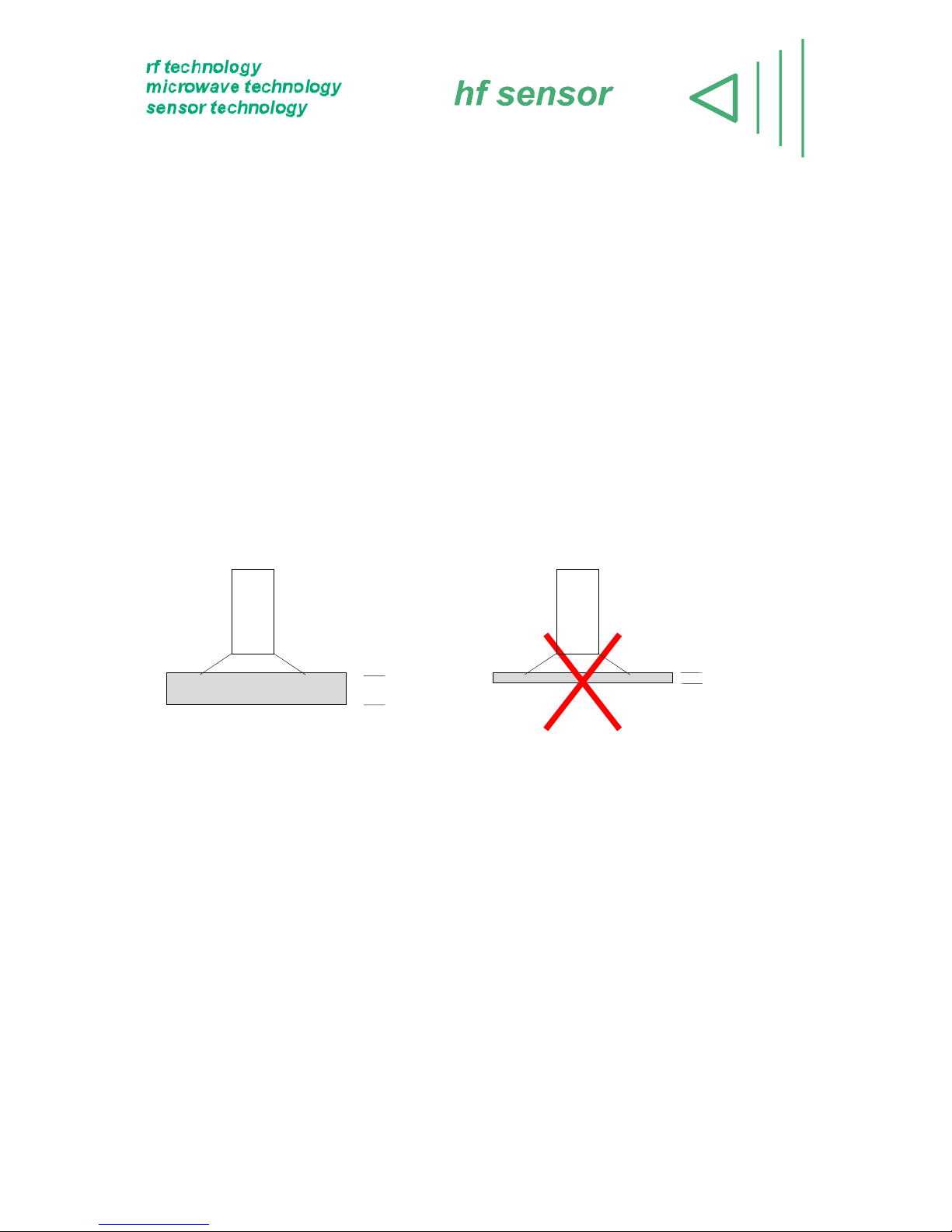
Minimum Thickness of Material
The field penetrates the material dependent on moisture and material type in the range
of 20 ... 30 cm. Therefore test objects must have a minimum thickness in this range. If
the material thickness is lower, measurement can be falsified.
If the test object - for instance a wall - is smaller than this minimum thickness, than parts
of the electromagnetic wave irradiated from the sensing head MOIST-PM V2 will be
reflected from the rear side of the test object and will superimpose with the reflexions
caused by moisture. Depending on moisture and material this effect can cause partially
strong falsification of the measured data.
> 20 ... 30 cm
< 20 cm
Page 30
30
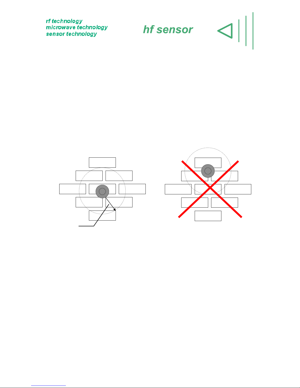
Minimum Distance from lateral bounds
The microwave field of the volume sensing head MOIST-PM V2 has significant lateral
extent. Therefore a minimum distance from lateral bounds must be kept to avoid
distortions of the measurement.
Simplified the interaction volume can be considered as a cylinder of a radius of about 10
... 15 cm. Therefore the minimum distance to lateral bounds is given with 10 cm.
Moisture measurement at a lower distance from lateral bounds of the test object can
cause a falsification of measured data.
For a reliable and exact measurement with the volume sensing head MOIST-P
make sure that the volume of the test object is large enough!
min. 10 cm
Page 31
31
6.4 Material specific calibration and moisture index
The sensing heads MOIST-PM V2 and MOIST-R1M V2 are material specific calibrated.
The calibration curves were generated in the moisture laboratory of hf sensor very
carefully.
At the moment calibrations are available for these materials:
- Brickwork new (density 1.6 ... 1.8 g/cm³)
- Brickwork old (density 1.1 ... 1.3 g/cm³)
- Clinker
- Wood (pine, spruce)
- Calcareous Sandstone
- Porous Concrete
- Sandstone
- Gypsum Floor (MOIST-R1M V2 and MOIST-R2M V2 only)
- Cement Floor (MOIST-R1M V2 and MOIST-R2M V2 only)
Other calibration curves will be added gradually following the progress in hf sensor’s
internal calibrations. Calibration curves can also be added customer specific. Hf sensor
will have great pleasure to offer such customer specific calibrations.
The material specific calibration is only valid for homogenous materials which have the
required minimum volume (→ 6.3). If the main constituent of a test object is known,
measurements will also be possible through thin surface layers (for instants plaster)
without significant falsification.
In real applications, building materials must be considered to be inhomogeneous. This
inhomogenity can be in the material itself or can correspond to the materials water
binding mechanisms or to the moisture distribution in the material.
That’s why measuring in such test objects always requires averages to be generated
from single measurements to get the required significance.
For the realisation of measurements in materials, whose calibration curves aren’t
known, and for relative measurements - for instance lateral moisture distributions Moisture Index can be used. Moisture Index is a dimensionless number between 0 and
4000.
Under the conditions described in 6.3 low Moisture Index means low water
content and high Moisture Index means high water content.
Page 32
32
7 Applications
Material types: Wood
Building Materials
Walls, Brickwork
Moisture Range: 0% < F < 80% (wet base, material specific)
0% < F < 400% (dry base, material specific)
Accuracy: 0,5% ... 2% achievable, material specific
Penetration Depth: MOIST-PM V2 up to 30 cm, material specific
MOIST-R1M V2 up to 3 cm, material specific
Temperature Range: 0 ... 50°C
Page 33
33
8 Scope of delivery
the handheld microwave moisture meter MOIST 350
the volume sensing head MOIST-PM V2 for moisture measurement in
the volume or kernel of material
the surface sensing head MOIST-R1M V2 for moisture measurement
in the outer surface layers of the material
carrying case
power supply (with battery charging circuitry integrated in the
handheld)
Options:
penetration applicator MOIST ENDO M
microwave sensing head MOIST-R2M V2 for moisture measurement in
the outer and medium layers of the material
microwave sensing head MOIST-DM V2 for moisture measurement in
the middle material layers
microwave sensing head MOIST-SM for moisture measurement in
deep material zones
the humidity probe MOIST-RH
software MOISTANALYZE for data transfer and graphical visualisation
(including interface cable)
MOIST 350 B and the software MOISTANALYZE be offered as a package.
Page 34
34
9 Safety Instructions
Charging of the NiMH-Accumulators must only happen in the MOIST 350 handheld.
Charging in common charging devices is strictly prohibited.
Hf sensor will not give any warranties for damages caused by the use of other batteries
or accumulators.
Interchanging of accumulators only by authorized personnel.
Please turn off the device before you plug in the power supply.
The connection or disconnetion of the sensing heads or USB-cable is only
allowed after the device is turned off.
Do not operate close to strong electromagnetic fields (arc welding, induction ovens
etc.), because moisture values can be falsified.
To guarantee safety and given technical parameters operation of MOIST 350 is only
allowed following this instruction manual.
Rights of ownership
The content of this user manual and texts, pictures and graphics in it are property of hf
sensor GmbH. Any kind of copy whatsoever as a whole or in parts only with permission
of hf sensor GmbH.
hf sensor GmbH 2014-01 Subject to change without notice
Page 35
35
10 Installation instruction for USB-driver unit
please make sure that you are endued with administrator rights when installing under
Windows xP
USB-cable has to be coupled with the measuring device MOIST 350 B and later on
connected with the PC via USB-cable/USB-interface
switching-on of measuring device MOIST 350 B
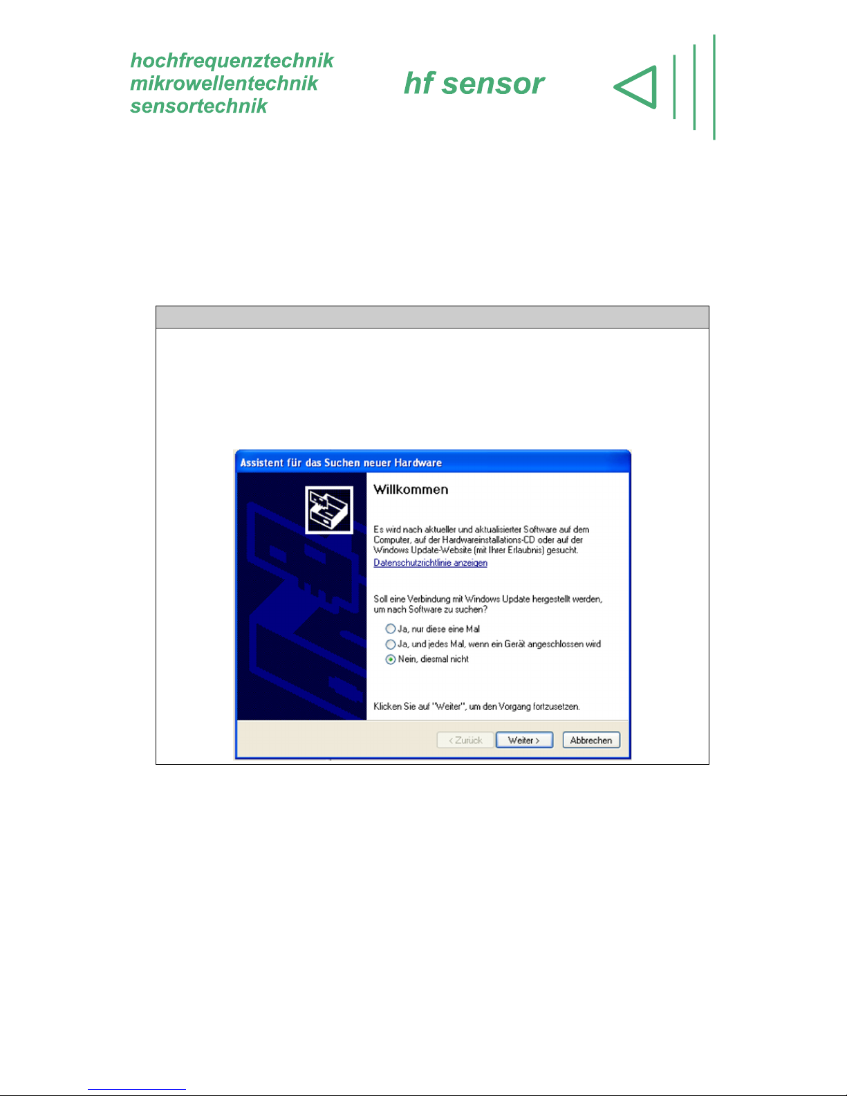
Betriebssystem Windows XP
If an USB-specific driver has not been installed yet, Windows will give a notice that
a new hardware component has been found. The Windows assistant therefore is
going to be run automatically. The USB-driver can be found on the installation-CD
MOISTANALYZE. Thus, a connection with Windows Update might not be needed.
Select the option No - not this time and follow the commands of the assistant!
Page 36
36
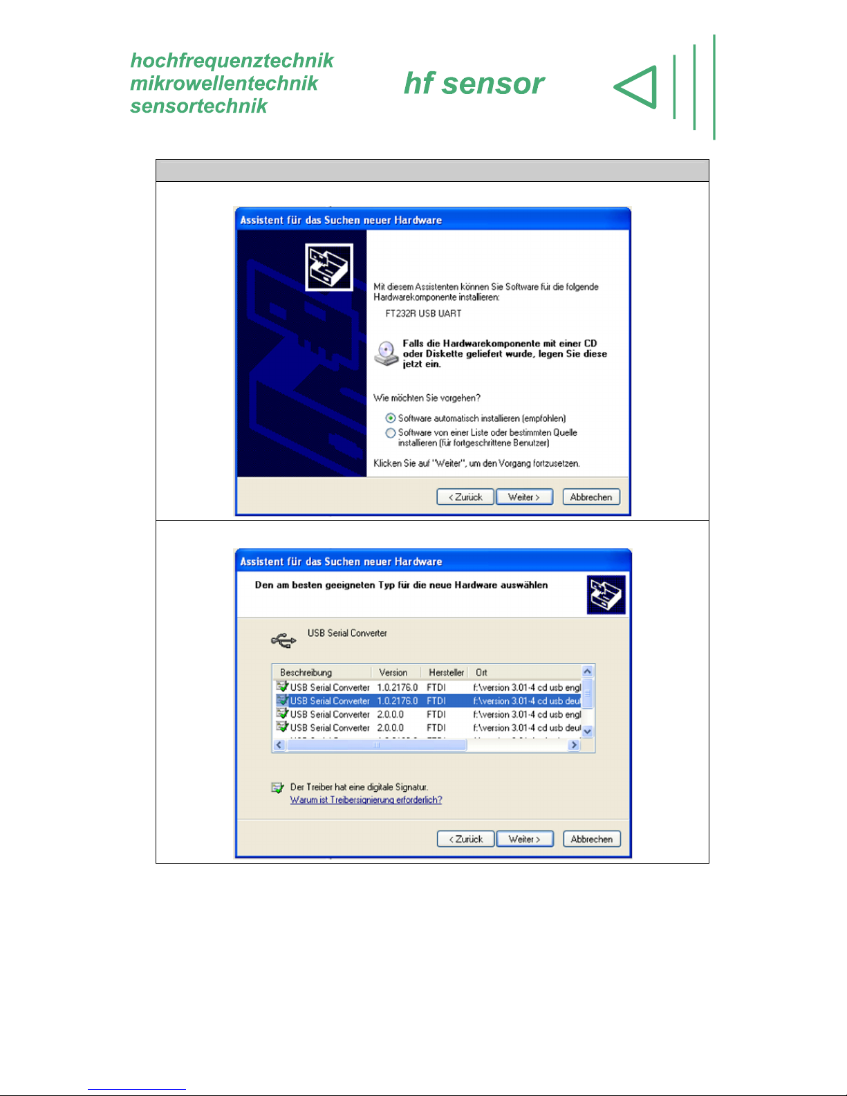
Betriebssystem Windows XP
The USB-driver can be found on the installation-CD MOISTANALYZE:
The CD will be browsed until a driver found will be recommended for installation:
Page 37
37
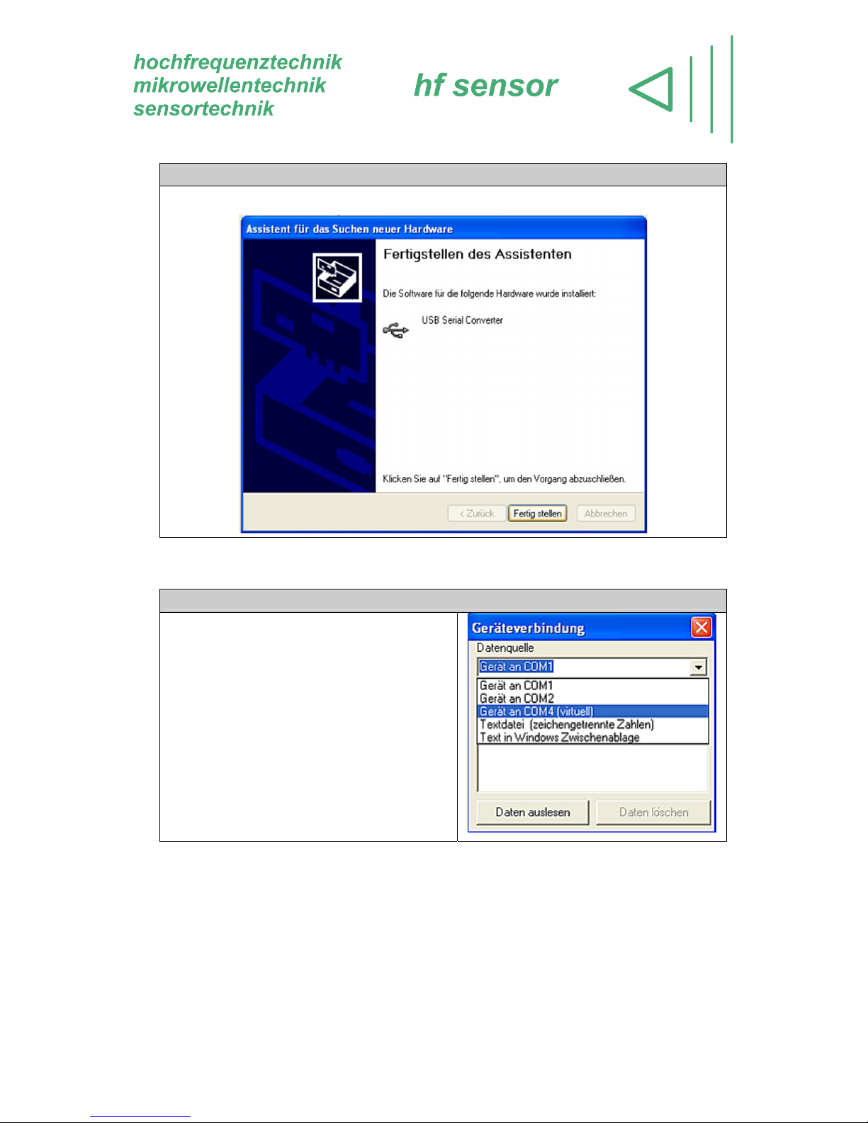
Betriebssystem Windows XP
Quit the Windows assistant after successful installation:
Start Software MOISTANALYZE
Daten auslesen
By using the software MOISTANALYZE
version 3.2 data will be transmitted from the
PC by selecting the right interfaces (virtual
COM-Port >= 9):
 Loading...