

Page 1

Stilling Chamber
Instruction
Manual
Stilling Chamber (Cat. # 70919)
HF scientific, inc.
3170 Metro Parkway
Fort Myers, FL 33916-7597
Phone: (239) 337-2116
Fax: (239) 332-7643
Page 2
HF scientific, inc.
Stilling Chamber Part # 20106
STILLING CHAMBER COMPLETE WITH AUTOMATIC AIR RELEASE
It is only used on applications where the OnLine Monitor is measuring a
flowing stream of water or other liquid. The stilling chamber is used to
remove air bubbles from the liquid before it reaches the flow through unit of
the on-line turbidimeter. Air bubbles may cause unstable or incorrect
readings on the monitor.
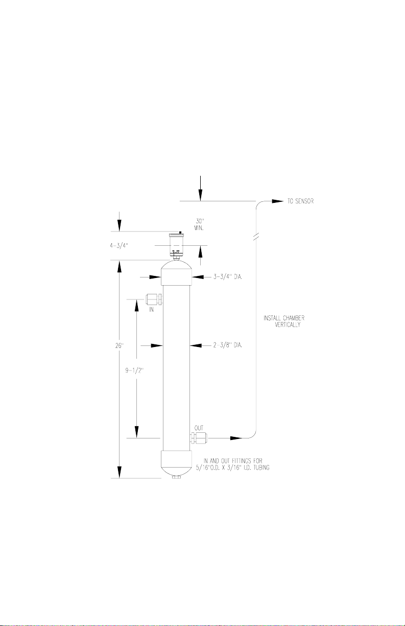
Figure 1
METHOD OF OPERATION
The stilling chamber is a cylinder approximately 2” (5cm) diameter x 26” (66
cm) long. The liquid enters the stilling chamber via the outlet fitting near
the top of the stilling chamber (see figure 1). As the liquid
Page 3

passes through the stilling chamber, its velocity becomes very low due to
the large diameter of the stilling chamber. This permits the fine air bubbles
in the liquid to rise to the top of the stilling chamber.
The automatic air vent in the top of the stilling chamber removes the air as
it collects at the top of the stilling chamber.
The stilling chamber should be located in the line before the liquid reaches
the sensor. The outlet from the stilling chamber should be run vertically at
least 30” (75cm) above the top of the automatic air release before being led
to the sensor.
The BRAUKMANN Automatic Air Vent has a maximum working pressure of
90 psi and maximum temperature range to 225°F (106° C). It is designed
for use on all types of hot water radiators, convectors, base board
convectors, heating units, venting pipes and fittings.
Figure 2 Shown in
OPERATING INSTRUCTIONS
Open Position
1. Before filling the system, make sure the red vent cap is securely
tight and that the valve is in the closed position (see figure 2) by
turning vent body clockwise. Use hands only to avoid damaging
the vent.
2. With the valve in the closed position, flush the system as required
to remove dirt, debris and contaminates.
3. Fill the system with the appropriate solution.
4. Start operation by turning the air vent body counter-clockwise to
the open position (see figure 2).
Page 4

5. Make sure the red vent cap is tightend all the way to the stop
position for proper operation. Use hands only to tighten.
RED VENT CAP
WITH LEAKAGE
BLACK COVER
ASSEMBLY
GUARD.
O-RING
SEAT AREAMAKE SURE
AREA IS FREE
OF DIRT AND
DEBRIS
CLEANING INSTRUCTIONS
VENT LEVER
SPRING
FLOAT
CONSTRUCTED
FOR EASY IN
LINE SERVICE.
SHUTOFF IS
BUILT-IN NO
DRAIN DOWN
REQUIRED.
Figure 3
1. Turn the vent body clockwise to the closed position, isolating the
vent from the system (see figure 2).
2. Remove the float assembly by unscrewing the top of the body
and lifting the black cover assembly up (see figure 3).
3. Carefully clean the seat area of any dirt or debris.
4. Carefully clean any dirt or debris from inside the vent chamber.
Page 5

5. Replace the float assembly, making sure that the O-ring is seated
properly (see figure 3).
6. Replace black cover assembly on air vent body. Using hands only
turn until handtight.
7. Operate by turning the air vent body counter clockwise to the
open position. Use hands only (see figure 3).
8. Make sure the red vent cap is tightend all the way to the stop
position for proper operation. Use hands only to tighten.
 Loading...