

Page 1

OPERAOPERA
OPERA
OPERAOPERA
TING & MAINTENTING & MAINTEN
TING & MAINTEN
TING & MAINTENTING & MAINTEN
ANCEANCE
ANCE
ANCEANCE
MANUMANU
MANU
MANUMANU
OIL CONTENT BILGE OIL CONTENT BILGE
OIL CONTENT BILGE
OIL CONTENT BILGE OIL CONTENT BILGE
ALAL
AL
ALAL
ALARMALARM
ALARM
ALARMALARM
Bilge Alarm CATALOG NO. 81099 (02/02)
Rev. 1.3
HF scientific, inc.
3170 Metro Parkway
Ft. Myers, FL 33916-7597
Phone: (239) 337-2116
Fax: (239) 332-7643
Page 2
At Sea SparAt Sea Spar
At Sea Spar
At Sea SparAt Sea Spar
ff
or the HF scientifor the HF scientif
f
or the HF scientif
ff
or the HF scientifor the HF scientif
icic
ic
icic
e Pe P
e P
e Pe P
,,
inc inc
,
inc
,,
inc inc
Qty. Description Cat.!No.
1In!line!calibrator 20098
2 Fuse!Ω !A/120V 50016
arar
ts Kitts Kit
ar
ts Kit
arar
ts Kitts Kit
. Bilg. Bilg
. Bilg
. Bilg. Bilg
Bilge!Alarm!Spare!Parts!Kit!Contents:
e e
AlarAlar
e
Alar
e e
AlarAlar
mm
m
mm
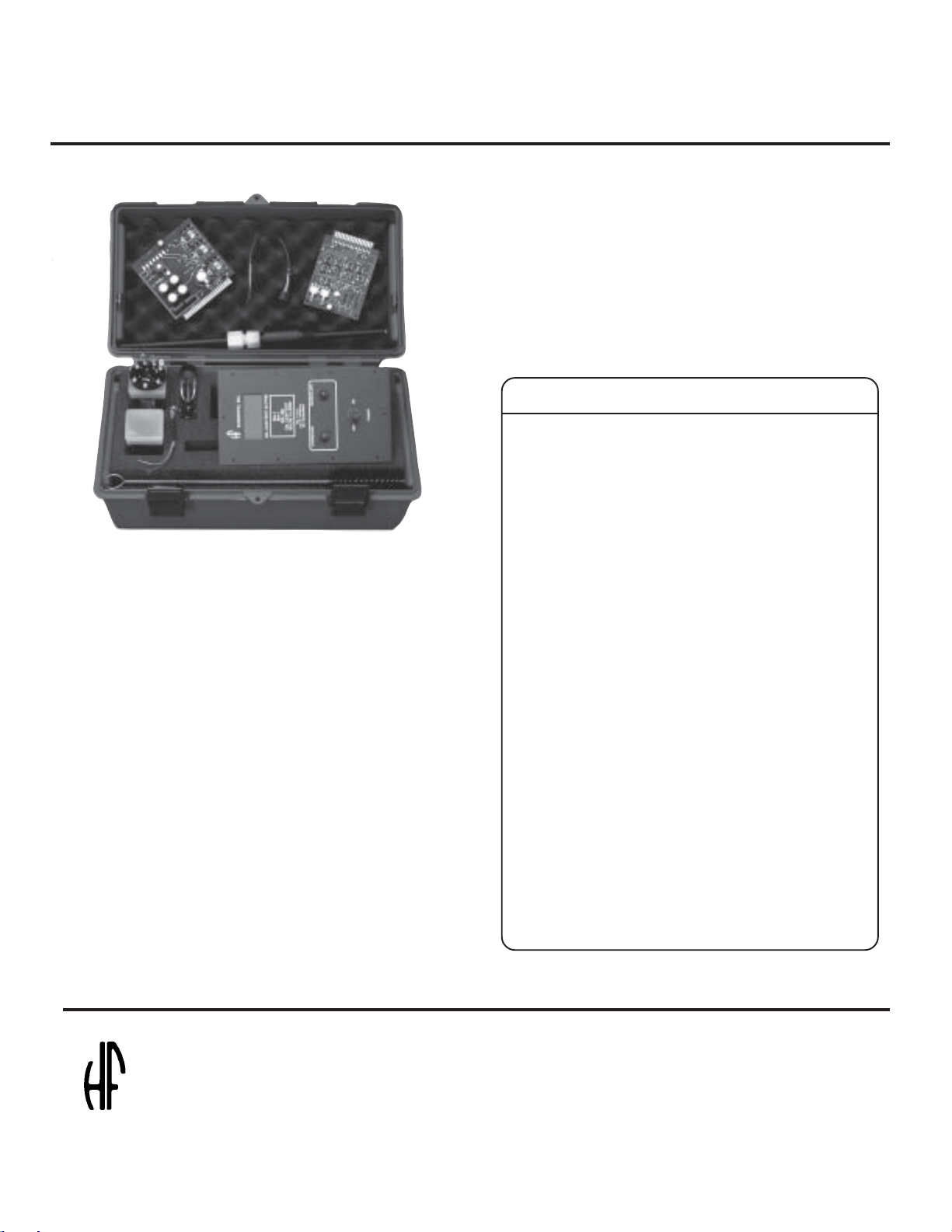
At Sea Spare Parts Kit
Cat. No. 81080
ï!!Clean,!calibrate!and!repair!your!instrument!in
!!!!the!field!or!at!sea
ï!!Avoid!rush!orders! for!spares!while!in!port
The!HF!Bilge! Alarm! Spare!Parts!Kit! contains! the!recommended!spare!parts!needed! for! standard! maintenance!and
repair.!!This!kit! contains! detailed!instructions! designed!to
allow!the!ship's!engineer!to!service!the!instrument!without
a!costly! port!service!call.
Save!40%!over!individually!priced!spare!parts!cost.
2Fuse!º!A / 2 4 0V 50017
1 Light!Detector!Assembly 80995
2 Lamps!for!Recirc./Overboard 81007
1 Photodiode! Assembly 81010
1 Side!Panel!Assembly 81025
1 Power!Supply!Board 81030
1 Amplifier!Board 81033
1 Instruction! Manual 81099
1 Cleaning!brush!for!sensor 81095
1 Rugged!plastic!case 81094
1 Source!Lamp 80996
scientifscientif
scientif
scientifscientif
Bilge Alarm (02/02)
Rev. 1.3
icic
ic
icic
,,
inc inc
,
inc
,,
inc inc
3170 Metro Parkway3170 Metro Parkway
3170 Metro Parkway
3170 Metro Parkway3170 Metro Parkway
Fort Myers, FL 33916-7597Fort Myers, FL 33916-7597
Fort Myers, FL 33916-7597
Fort Myers, FL 33916-7597Fort Myers, FL 33916-7597
Phone: (239) 337-2116Phone: (239) 337-2116
Phone: (239) 337-2116
Phone: (239) 337-2116Phone: (239) 337-2116
Fax: (239) 332-7643Fax: (239) 332-7643
Fax: (239) 332-7643
..
.
..
Fax: (239) 332-7643Fax: (239) 332-7643
Rev 4/98Rev 4/98
Rev 4/98
Rev 4/98Rev 4/98
Page 3

IMPORTANTIMPORTANT
IMPORTANT
IMPORTANTIMPORTANT
Calibration / Cleaning KitCalibration / Cleaning Kit
Calibration / Cleaning Kit
Calibration / Cleaning KitCalibration / Cleaning Kit
Note: This unit has been factory calibrated and should not require further adjustment.
Your Oil Content Bilge Alarm requires a calibration check every 3 - 4 months or anytime either mechanical or electrical
adjustments have been made to the unit.
The calibration procedure is detailed in this instruction manual and requires HF Part # 20098.
This kit should be ordered now so that material is available when calibration is required due to time constraints,This kit should be ordered now so that material is available when calibration is required due to time constraints,
This kit should be ordered now so that material is available when calibration is required due to time constraints,
This kit should be ordered now so that material is available when calibration is required due to time constraints,This kit should be ordered now so that material is available when calibration is required due to time constraints,
equipment adjustment or compliance agency request.equipment adjustment or compliance agency request.
equipment adjustment or compliance agency request.
equipment adjustment or compliance agency request.equipment adjustment or compliance agency request.
Please complete and mail to HF scientific, inc. 3170 Metro Parkway, Ft. Myers, Florida, U.S.A. 33916-7597.
PURCHASE ORDER FORMPURCHASE ORDER FORM
PURCHASE ORDER FORM
PURCHASE ORDER FORMPURCHASE ORDER FORM
Ship to: Bill to:
P.O. Number (if required):
Name:
Phone:
Qty. Description Cat. No. Price (each)
1 Oil Content Bilge Alarm Calibrator Kit & 20098 $230.00
Cleaning Brush
Bilge Alarm (02/02)
Rev. 1.3
Page 4

CONTENTSCONTENTS
CONTENTS
CONTENTSCONTENTS
PAGE
I. SPECIFICATIONS .................................................................................................................................1
II. WARNING NOTICE ..............................................................................................................................2
III. OPERATION...........................................................................................................................................2
IV. INSTALLATION ....................................................................................................................................2
V. ALARM CONNECTIONS .....................................................................................................................2
VI. START-UP ..............................................................................................................................................3
VII. CALIBRATION ......................................................................................................................................3
VIII. CALIBRATION CHECK .......................................................................................................................3
IX. ISOLATION VALVES ...........................................................................................................................4
X. SETTING ALARM LEVEL...................................................................................................................4
XI. INDICATING LAMPS ...........................................................................................................................4
XII. CLEANING SENSING MODULE WINDOWS ...................................................................................4
XIII. REPLACING SOURCE LAMP .............................................................................................................4
XIV. REPLACING SENSING MODULE MEASUREMENT DETECTOR ...............................................5
XV. REPLACING SENSING MODULE FAILSAFE LIGHT DETECTOR ..............................................5
XVI. TROUBLE SHOOTING GUIDE ...........................................................................................................6
XVII. TEST PROCEDURES FOR POWER SUPPLY BOARD ....................................................................7
XVIII. SPARE PARTS .......................................................................................................................................8
XIX. WARRANTY ..........................................................................................................................................10
LIST OF FIGURESLIST OF FIGURES
LIST OF FIGURES
LIST OF FIGURESLIST OF FIGURES
1 SYSTEM INSTALLATION DIAGRAM ..............................................................................................11
2 SENSOR INSTALLATION DIAGRAM...............................................................................................12
3 WIRING DIAGRAM ..............................................................................................................................13
4 INTERCONNECT WIRING ..................................................................................................................14
5 LOCATION OF PARTS .........................................................................................................................15
6 LOCATION OF PARTS .........................................................................................................................16
7 SENSOR CONNECTIONS ....................................................................................................................17
8 CONTROL MODULE OUTLINE .........................................................................................................18
9 SENSING MODULE OUTLINE ...........................................................................................................19
10 DISPLAY BOARD SCHEMATIC ........................................................................................................20
11 POWER SUPPLY SCHEMATIC ..........................................................................................................21
12 AMPLIFIER BOARD SCHEMATIC ....................................................................................................22
Bilge Alarm (02/02)
Rev. 1.3
Page 5

I. SPECIFICATIONS
Range 0 - 100 PPM
Outputs Recorder Output: 0-10 V.D.C., minimum impedance 500 ohms.
Digital display: 2 1/2 digit. Display Readings & Alarm Set Point.
Relay: Contacts rated at 5 amps. 120VAC, 28Vdc for Resistive Load.
Activates upon:
1.High alarm.
2.Light Source Burn Out.
3.Fouled windows.
Normal Operation: Fail safe; loss of power causes alarm.
Calibration check Check switch
Operating Conditions Power: 120/240 Volts
Protection: Fused primary
Temperature: 0-50 degrees C (122 degrees F.) (NOTE: When ambient
temperatures drop below 0 degrees C. (32 degrees F.), (Sensing Module must
be drained).
Humidity: To 95%
Vibration: - From 2Hz to 13.2 Hz + 1mm amplitude.
Rolling Angle: 0-22.5 degrees
Critical Measurement Response Time:
Display - 5 seconds or less.
Alarm - 16 seconds or less
Measured Flow Rate: 40 g.p.m. maximum.
Measured Pressure Range: 0-60 p.s.i.
Sensing Module Weight: 6 lbs., 11 oz. (3.03 kg)
Threads: 1" N.P.T. pipe (customer supplied).
Dimensions: (Refer to Figure 9)
Construction Materials: Body - Cast aluminum, neoprene O-Ring seals,
Borosilicate pressure windows.
Interconnecting Cable 7 Conductor, shielded. Rated 80 degrees C., 300V. U.L. listed/CSA Certified.
15 ft. supplied.
Indicating/Control Module Weight: 19 lbs. (8.62 kg)
Dimensions: (Refer to Figure 8) Electronic components are mounted in an oil
tight J.I.C. Enclosure with holes for 1/2" conduit.
+ 10%, 50/60 Hz
- From 13.2 Hz to 80 Hz with acceleration to .7G.
Amplifier P.C. Board has a plug-in connector and is fastened to the chassis for rigidity. It includes trim pots and Alarm
Set and Calibration switches (Refer to Item A, Figure 5).
Power Supply P.C. Board includes test points, a plug-in connector, and is also fastened to the chassis (Refer to Item
C, Figure 5).
Bilge Alarm (02/02)
Rev. 1.3
Page 1
Page 6

II. WARNING
The Sensing Module and the Indicating/Control Module
are shipped with the Interconnecting Cable connected
for reasons of convenience; however, electrical
installation including routing of the Interconnecting
Cable, power connections, calibration and servicing
should only be done by qualified electricians and in
accordance with applicable codes and regulations.
Caution should be exercised when working on
components inside the Indicating/Control Module while
power is on. Coming in contact with live components
may cause electrical shock or damage to equipment.
If there is a possibility of voltage spikes or power surges
to the instrument’s power supply module, an approved
line suppressor is recommended.
III. OPERATION
Cleaned water from oily-water filtering equipment is
continuously monitored.
separators must incorporate a suspended particle
filter. ”
Piping for the Sensing Module is arranged in the outlet
line of the Oily-Water Filtering Equipment. Cleaned
bilge water, up to 60 psi, flows through the module past
optical windows where the measurement is made. A
pre-focused incandescent light source provides a light
beam which passes through the bilge water. A detector,
placed at a 90° angle to the incident light beam, measures
light scattered by the dispersed oil in the bilge water. An
electrical output from the detector is transmitted through
a cable to the Indicating/Control Module where it is
processed. The measurement is displayed on the panel
in “PPM”.
The digital display on the front panel shows 2 1/2 digits
and can indicate readings up to 100 PPM accurately.
Readings over 100 PPM are not reliable. An “ON/OFF”
switch, for providing power to the Bilge Alarm, is also
located on the panel.
IV. INSTALLATION
The Bilge Alarm measures and displays the
concentration level of dispersed oil in the flowing
stream of cleaned water. The instrument consists of a
Sensing module and an Indicating/Control module. Oil
content of the cleaned bilge is continuously shown on
the Indicating/Control module’s digital display. An
adjustable alarm set-point function, used to set the
allowable oil concentration level, is located inside the
Indicating/Control module. When the Sensing Module
determines that the oil level exceeds the setpoint value,
for longer than 15 seconds, a relay operates the lights on
the display panel of the Indicating/Control Module.
Green for “OVERBOARD” changes to red for
“RECIRCULATE”. Simultaneously two sets of relay
contacts activate independent alarm circuits. When the
oil level in the effluent water is once more below the
set-point value, the green lamp for “OVERBOARD”
will glow and the red lamp for “RECIRCULATE” will
shut off. The relay contacts will also deactivate. The
above performance is contingent upon and consistent
with the recommendations stated in the IMO
Recommendations for Performance and Test
Specifications for Oil Content Meters:
“Non foaming detergents should not be used in the
bilges for cleaning purposes, as the emulsifying
effects of some compounds seriously affect the
operation of the equipment. Non soluble suspended
solids can give false high readings. The oil water
Install the Sensing Module using 1" piping after the
Oily-Water Filtering Equipment.
To permit use of the Bilge Alarm Calibration Kit, as
well as a laboratory cleaning brush to clean the windows
by brushing through when required, connect piping as
shown in Figure #2. Sensor must be mounted vertically
as shown in Figure 2, page 12, to allow the use of
calibration kit Part No. 20098.
Piping should be in accordance with 46 C.F.R.
56.01-IOD (U.S.Coast Guard).
Connect Sensing Module to Indicating Control Module,
as per Figures #3, #4, #7. Seal the cable entrance to the
Sensing Module against the penetration of water vapor.
Connect Power Source through fused switch to
Terminals #6 and #7, in the Indicating/Control Module
per Figures #3 and #4. Connect ground to Terminal #E9
per Figures #3 and #6. Selection of 115 volt or 230 volt
operation can be made with the switch in the Indicating/
Control Module as shown in Figure #6, Item A. Use two
1/2 Amp fuse only for 120V; use two 1/4 Amp fuse for
240V.
NOTE: Change both fuses for either mode of operation.
V. ALARM CONNECTIONS
Contacts for the Alarm Relay are located in the Indicating/
Control Module. These are “Dry” contacts with ratings
Bilge Alarm (02/02)
Rev. 1.3
Page 2
Page 7

of 5 amps at 120VAC or 28 VDC resistive.
There are two sets of contacts which may be used to
operate valves, sound alarms, etc. These are wired as
follows refer to Figure #3 and #4. Note that the relay is
de-energized in the Alarm condition.
across terminals 10 (neg.) and 11 (pos.) in the
Indicating/Control Module, (Refer to Figure
#4).
EXAMPLES:
TB3 Set #1 Terminal #17 - Closed in the Alarm
Condition
Terminal #18 - Common
Terminal #19 - Open in the Alarm
Condition
TB3 Set #2 Terminal #20 - Closed in the Alarm
Condition
Terminal #21 - Common
Terminal #22 - Open in the Alarm
Condition
VI. START-UP
1. Turn on the Power Switch located on the Indicating/
Control Module.
2. Allow the instrument to warm-up for
approximately 30 minutes for stabilization. It is
recommended that the power to the instrument be
left on continuously except when servicing is
required.
3. Run clean oil-free water through the Sensing
Module.
4. Adjust the Zero Pot in the Indicating/Control
Module (Item B, Figure #6) to cause Digital
Display to indicate 00 PPM. NOTE: Negative
readings on the Digital Display are indicated by a
negative sign lighting up to the left of the Display
Digits. When making adjustments do not
over-adjust to negative values.
VII. CALIBRATION
The instrument has been factory calibrated in PPM.
However, if it is desired to check calibration, the
following procedure should be followed:
1. Run clean oil-free water through the Sensing
Module and adjust “Zero” control.
2. Using an In-Line Calibration Holder, HF Part
No. 20098, place a suitable calibration standard,
equivalent to a known value of oil in water, in the
Sensor.
3. When conditions have stabilized, observe
Recorder Output reading; it should read 10 Volts
DC for 100 PPM and any proportional linear
value between zero and 10 volts for lower values
(see example below). Recorder output is obtained
PPM (Oil in Water) Recorder Output Reading
100 PPM 10 Volts
15 PPM 1.5 Volts
4. Calibrate the Recorder Output to correct value
by adjusting the Trim Pot marked REC on the
Amplifier P.C. Board, (Refer to Item D, Figure
#5).
5. Adjust the Trim Pot marked DVM, on the same
P.C. Board, to cause the Digital Display to read
the correct value in PPM.
NOTE: 1. Whenever the value of the oil free water
changes, it can be “Calibrated Out” by simply
running a sample of the oil free water through the
Sensing Module and adjusting the “ZERO” Pot
in the Indicating/Control Module (Item B, Figure
#6) to obtain a reading of “00” on the Digital
Display.
2. Calibration should be checked after
components have been replaced, i.e., P.C. Board,
or Lamp, etc.
3. Whenever the instrument is re-calibrated a
new “Cal Check” number should be obtained
and recorded. See “Calibration Check” and follow
steps 1 through 4.
VIII. CALIBRATION CHECK
This is a procedure used to check that the electronic
function is still within the limits set by the Calibration
Check Number.
1. Open the Indicating/Control Module.
2. Activate the CAL Check Switch (Item F, Figure
5, Spring Return) and note reading.
3. With the Cal Check Switch returned to its normal
position and note reading.
4. Subtract the reading obtained in Step #3 above
from that obtained in Step #2.
5. Compare the value obtained, which is the current
Cal Check value, to the Cal Check number
supplied with the instrument, which is affixed to
the Indicating/Control Module Chassis. Should
this current value vary by more than three (3)
units from the original value, then the instrument
should be re-calibrated.
Bilge Alarm (02/02)
Rev. 1.3
Page 3
Page 8

IX. ISOLATION VALVES
6) even though the water appears clean, or when the
display shows a PPM count less that the true value.
Isolation valves should be operated to shut-off flow from
the Oily-Water Filter under each of the following
conditions:
- Conducting service on the Sensing Module.
- Calibration
- Replacement of Sensing Module
Otherwise always ensure that the valves are positioned to
provide flow to the Sensing Module.
X. SETTING ALARM LEVEL
Activate “Alarm Set” switch on the Amplifier P.C. Board
in the Indicating/Control Module (Item E, Figure 5).
While holding the “Alarm Set” switch “On” (spring
return) the Digital Display will read the Alarm Set Value.
Adjust the “Alarm” Trim Pot (Item G, Figure 5) while
holding the Switch “On”, to cause the Digital Display to
read desired Alarm Level. Release the “Alarm Set” Switch.
The Alarm Relay will activate 15 seconds after the PPM
Oil-in-Water content has constantly exceeded the Alarm
Set value.
XI. INDICATING LAMPS
Green light is ON, Red light is OFF, whenever Unit is
operating under Normal Conditions.
Red Light is ON and Green Light is OFF, during Alarm
Conditions.
The reading must remain over the alarm set value for 15
seconds to activate the alarm relay.
XII. CLEANING THE SENSING MODULE WINDOWS
The Sensing Module through which the fluid flows and in
which a light beam is projected to measure oil content in
the effluent contains three precision glass windows.
One indication that these windows may require cleaning
is when the system enters the recirculation mode and
remains in this mode even though a sample of the effluent
from the Oily-Water Filter appears clean.
A periodic cleaning routine should be established to
preclude the system from remaining in the recirculation
mode because of a fouled flow channel. The frequency of
the cleaning operation should be determined on the basis
of the type of fluids being processed and how often the
flow channel becomes contaminated during initial system
use. Procedure for cleaning is as follows:
1. Turn off the flow to the Sensing Module.
2. Remove the clean-out plugs shown in Figure 2.
3. Use a mild detergent on a laboratory cleaning brush
and pass the brush through the Sensing Module
flow channel several times. Then rinse with clean
water.
4. Replace the clean-out plugs.
5. Resume normal flow.
XIII. REPLACING SOURCE LAMP ASSEMBLY
The Source Lamp in the Sensing Module may burn out
occasionally and require replacement. This failure will
cause the Bilge Alarm to go into an Alarm Condition
(Refer to Figure 7).
1. Turn OFF the Power Switch at the Indicating/
Control Module.
2. Remove the four screws in Sensing Module End
Cap and remove the Sensing Module End Cap.
3. Unscrew all lug connections except at positions #1
and #2. Save all the screws as they will be needed
later.
4. Cut the shield wire for Failsafe Light Detector at
position #2.
5. Remove screws #8 & #9 and remove the Source
Lamp Assembly.
6. Replace source lamp assembly with new unit.
Check that orientation is correct, then reinstall
screws #8 & #9.
7. Replace all lug connections at the correct positions.
8. Solder shield wire for Failsafe Light Detector to
solder lug at position #2.
9. Replace Sensing Module End Cap and fasten four
screws.
10. Turn Power Switch ON at Indicating/Control
Module.
11. This completes the Source Lamp Assembly
replacement. Proceed to Section VII (Calibration)
and perform calibration as described.
Cleaning may also be required when oil-free water requires
considerable adjustment on the Zero Pot (Item B, Figure
Bilge Alarm (02/02)
Rev. 1.3
Page 4
Page 9

XIV. REPLACING SENSING MODULE
MEASUREMENT DETECTOR (Refer to Figure 7)
1. Turn OFF the Power Switch at the Indicating/
Control Module
2. Remove the four screws in Sensing Module End
Cap and remove the Sensing Module End Cap.
3. Cut wires at positions #5, #6, and #7.
4. Remove the brass Measurement Detector Cap,
located on the side of the sensor.
5. Remove the Measurement Detector Spacer.
6. Remove the Measurement Detector Assembly
including wires cut in step #3 above.
7. Install the replacement Measurement Detector
Assembly by feeding the wire of the assembly
though hole.
8. Carefully seat Measurement Detector in position.
9. Replace Light Detector Spacer and brass cap.
10. Solder three wires attached to Measurement
Detector to lugs on position #5, #6 & 7 (black wire
to #5, shield wire to #6 and red wire to #7).
11. Replace Sensing Module End Cap.
12. Turn ON the Power Switch at the Indicating/Control
Module and ensure that the Bilge Alarm is
responding correctly to changes in oil concentration.
13. This completes the Measurement Detector
replacement. Proceed to Section VII (Calibration)
and perform calibration as described.
8. Place replacement Light Detector Assembly and
Spacer in position and replace the Light Detector
Cap with the four screws previously removed.
9. Solder three wires attached to Light Detector
Assembly to lugs on positions #2, #3, and #4,
(shield wire to #2, black wire to #3, and red wire to
#4).
10. Replace the Sensing Module End Cap and Light
Detector Cap.
11. Turn ON the Power Switch at the Indicating/
Control Module and ensure that the Bilge Alarm is
in the normal condition with clean water in the
Sensing Module. Insert opaque object in Sensing
Module Flow channel to block light to Light
Detector to ensure that the Bilge Alarm goes into
the Alarm Condition.
12. This completes the Failsafe Light Detector
replacement procedure.
XV. REPLACING SENSING MODULE FAILSAFE
LIGHT DETECTOR (refer to Figure 7)
NOTE: The Light Detector is a failsafe feature which
draws attention to lamp burn-out or opaque
obstruction conditions and will not normally need
replacement during the life of the instrument).
1. Turn OFF the Power Switch at the Indicating/
Control Module.
2. Remove the four screws in Sensing Module End
Cap and remove the Sensing Module End Cap.
3. Cut the black and red wires at positions #3 and #4
and shield wire at position #2.
4. Remove the four screws in Light Detector Cap
located on opposite end of the Sensing Module and
remove Cap.
5. Remove Light Detector Spacer.
6. Remove Light Detector Assembly including wires
cut in #3 above.
7. Feed the three wires on the replacement Light
Detector Assembly through to positions #2, #3, and
#4.
Bilge Alarm (02/02)
Rev. 1.3
Page 5
Page 10

XVI. TROUBLE-SHOOTING GUIDE
SYMPTOMS PROBABLE CAUSE CORRECTIVE ACTION
Digital Display and/or indicating
lights do not light up.
Unit stays in recirculation mode when
reading is below alarm set point.
Digital display does not change with
changing concentration of oil.
1. No power to Indicating/Control
Module.
2. Blown fuses.
3. Defective power supply board.
4. Indicating lamp loose or burned
out.
1. Sensing Module Source Lamp
burned out.
2. Defective Failsafe Light Detector.
3. Alarm Relay Defective.
4. Defective Power Supply Board.
5. Opaque Obstruction in flow
channel.
1. Defective Amplifier Board.
2. Defective Digital Display.
3. Open leads from sensor.
4. Defective Measurement Detector
Sensing Module.
1. Turn on power switch. Check
facility input power source.
2. Replace fuses.
3. Test power supply board as
outlined under Test Procedures
and replace if defective.
4. Insert lamps properly or replace.
1. Replace Source Lamp. Re-check
calibration.
2. Replace Failsafe Light Detector.
3. Replace relay.
4. Test Power supply board as
outlined under Test Procedures
and replace if defective.
5. Clean sensing module windows
with detergent and a brush.
1. Replace amplifier board (Item
A, Figure 4) and re-calibrate.
2. Replace complete Front Panel
Assembly containing Digital
Display Indicating Lights, etc.
3. Inspect Leads and connecting
wiring for breaks.
4. Replace measurement detector.
Digital display shows negative but
Alarm and Recirculate light is on.
Bilge Alarm (02/02)
Rev. 1.3
1. Sensing Module Source Lamp
Defective.
2. Defective Amplifier PC Board.
3. Defective Digital Display.
4. Fouled windows in flow channel.
Page 6
1. Replace Source Lamp in Sensing
Module.
2. Replace amplifier PC board (Item
A, Figure 5) and recalibrate.
3. Replace complete Front Panel
Assembly.
4. Clean Sensing Module Windows
with detergent and a brush.
Page 11

XVI. TROUBLE-SHOOTING GUIDE (cont.)
SYMPTOMS PROBABLE CAUSE CORRECTIVE ACTION
Readout shows negative.
When oil concentration as indicated
by the digital Display, goes above
Alarm Set Point, Controls stays in
“Overboard” condition and does not
change to “Recirculate.”
“Cal Check” reading too high (see
“Calibration Check”).
1. Cleaner oil free water.
2. Defective amplifier PC board.
3. Defective Digital Display.
1. Defective Alarm Relay.
2. Defective Amplifier Board.
3. Defective Failsafe Light Detector.
1. Dirty Sensing Module Source
Lamp.
2. Defective Sensing Module
Source Lamp.
3. Defective Measurement Detector
in Sensing Module.
1. Adjust zero. See “Start-up.”
2. Replace amplifier PC Board
(Item A, Figure 5) and recalibrate.
3. Replace complete Front Panel
Assembly.
1. Replace Relay.
2. Replace Amplifier PC Board
(Item A, Figure 5) and recalibrate.
3. Replace complete Front Panel
Assembly.
1. Clean Sensing Module
windows.
2. Check Sensing Module
Source Lamp and replace if
necessary.
3. Replace Measurement
Detector.
XVII. TEST PROCEDURES FOR POWER SUPPLY BOARD (LOWER PC BOARD IN Figure 3)
1. Turn Power OFF.
2. Remove Amplifier P.C. Board (Item A, Figure 5).
3. Unplug the Front Panel Harness Plug from the Socket, Item B, Figure 5.
4. Unplug the voltage plug from the socket, Item C, Figure 6.
5. Plug into socket (Item H, Figure 5) the Dummy Test Plug (Part #80276, supplied with instrument).
6. Turn Power ON.
7. Using a D.C. Volt Meter measure the voltages at the test points, i.e. between common (com) and each test point
on Power Supply Board. They should be within + 10% of value indicated and they should be stable.
8. If the voltages are not as indicated on every test point then replace Power Supply Board.
9. After testing and replacing Power Supply Board, if required, then turn Power OFF.
10. Remove Dummy Test Plug and reinstall Amplifier P.C. Board and replace Front Panel Harness Plug in socket Item
C, Figure 6.
11. Reinstall the voltage plug into the voltage socket.
12. Turn Power ON.
Bilge Alarm (02/02)
Rev. 1.3
Page 7
Page 12

XVIII. SPARE PARTS
RECORD
R6
C1
C2
+
+
1
D.V.M.
R7
C7
32 4 5 6
80101
ALARM
R8
Q1
SW1
R10
R1
+
R9
R2
C3
R4
C4
+
U3U1
C6
REC ALM
879 1011
SW2
C9
U6
C5
U5
U4
U2
R3
80103
12
13 1415
COM
1
+2.5
+5-5+15-15
ASSY 81030
+24
22
Amplifier P.C. Board Assembly
Catalog No. 81033
Qty. 1
SCIENTIFIC, INC.
OIL CONTENT IN PPM
BA-1
MA-1
BA-100
OIL CONTENT
BILGE ALARM
Mfg. in U.S.A.
U.S.C.G. APPROVAL
NO. 162.050/3009/1
OVERBOARD
RECIRCULATE
ON
OFF
POWER
Control Panel Complete w/Digital Display Lamps and
Switch
Catalog No. 81025
Qty. 1
Power Supply P.C. Board Assembly
Catalog No. 81030
Qty1
LAMP
U
U
U
U
U
SHLD
Vo
Vcc
Source Lamp Assembly
Catalog No. 80996
Qty. 1
Bulbs for Recirculate and Overboard Lamps
Catalog No. 81007
Qty. 2
Bilge Alarm (02/02)
Rev. 1.3
Fuses, 1/2 Amp. SLO-BLO (110V) Catalog No.
50016
Qty. 2
Fuses, 1/4 Amp. SLO-BLO (220V) Catalog No. 50017
Qty. 2
(Pictures not available)
Page 8
Page 13

XVIII. SPARE PARTS (Cont'd)
Relay
Catalog No. 80134
Qty. 1
In-Line Calibrator Kit & Cleaning Brush
Catalog No. 20098
(Optional)
Qty. 1
Photo Diode Assembly
Catalog No. 81010
Qty. 1
Failsafe Light Detector
Catalog No. 80995
Qty. 1
Bilge Alarm Spare Parts Kit
(See literature at front of manual)
Catalog No. 81080
Bilge Alarm (02/02)
Rev. 1.3
(Optional)
Qty. 1
ORDER FROM:
HF scientific, inc.
3170 Metro Parkway
Fort Myers, Florida 33916-7597
Phone: (239) 337-2116
Fax: (239) 332-7643
Page 9
Page 14

XIX. WARRANTY
HF scientific, inc., as vendor, warrants to the original purchaser of the instruments to be free of defects in material and
workmanship, in normal use and service, for a period of one year from date of delivery to the original purchaser. HF scientific,
inc.’s, obligation under this warranty is limited to replacing, at its factory, the instrument or any part thereof. Parts which by
their nature are normally required to be replaced periodically, consistent with normal maintenance, specifically lamps
including fluorescent backlight, reagent, sensors, desiccant, electrodes, and fuses are excluded. Also excluded are accessories
and supply type items.
Original purchaser is responsible for return of the instruments, or parts thereof, to HF scientific, inc.’s factory. This
includes all freight charges incurred in shipping to and from HF scientific, inc.’s factory.
HF scientific, inc. is not responsible for damage to the instrument, or parts thereof, resulting from misuse, negligence or
accident, or defects resulting from repairs, alterations or installation made by any person or company not authorized by HF
scientific, inc.
HF scientific, inc. assumes no liability for consequential damage of any kind, and the original purchaser, by placement
of any order for the instrument, or parts thereof, shall be deemed liable for any and all damages incurred by the use or misuse
of the instruments, or parts thereof, by the purchaser, its employees, or others, following receipt thereof.
Carefully inspect this product for shipping damage, if damaged, immediately notify the shipping company and arrange
an on-site inspection. HF scientific, inc. cannot be responsible for damage in shipment and cannot assist with claims without
an on-site inspection of the damage.
This warranty is given expressly and in lieu of all other warranties, expressed or implied. Purchaser agrees that there is
no warranty on merchantability and that there are no other warranties, expressed or implied. No agent is authorized to assume
for HF scientific, inc. any liability except as above set forth.
HF scientific, inc.
3170 Metro Parkway
Fort Myers, Florida 33916-7597
Phone: (239) 337-2116
Fax: (239) 332-7643
Bilge Alarm (02/02)
Rev. 1.3
Page 10
Page 15

System Installation Diagram
Figure 1
Bilge Alarm (02/02)
Rev. 1.3
Page 11
Page 16

Bilge Alarm (02/02)
Rev. 1.3
Sensor Installation Diagram
Figure 2
Page 12
Page 17

U
WHT
4
3
RECIRCULATE
V/BLK
DIGITAL MODULE 81020
OVERBOARD
V/BLK
GRN
7
2
8
9
3
4
JP6
-5V
+5V
COM.
COM.
22
21
2011
CONT.
+12V
1918
+24V
Vc
1615
Vcc
J3
POWER SUPPLY MODULE 81030
+2.5V
+5V
10
9
-5V
87
+15V
~
-15V
65
COM.
~
T1
4
T1
3
T1
21
T1
BLK
POWER
1
2
GRN/WHT/BLK
WHT
BLK
6
1
1
4
3
WHT
WHT WHT
JP1
BLK
96
328
74
1
JP5
4
SW-2
BLK
CR1
K1
98765
11
9
J2
7
6
-15V
5
3
2
AMPLIFIER MODULE 81033
1
+15V
+15V
COM.
E1
E2
E3
-15V
ARC
RC3
SUPPRESSORS
EACH NETWORK
600VDC/250VAC
470 OHM, 0.1MFD
INDICATOR PANEL
1.0A
%8)+
0.5A
!"8)+
1.5A
"8)+
1
10
RC4
SENSOR
REMOTE
RED
BLACK
ORANGE
YELLOW
LAMP
-
+
Vc
IN THE ALARM CONDITION.
MAL OPERATION AND DE-ENERGIZED
RELAY IS ENERGIZED DURING NOR-
CONDITION.
*RELAY IS SHOWN IN DE-ENERGIZED
WHT/RED
#8)+#8)+
CT
CT
WHT
BLK
U
115V230V
2
1
3
4
5
6
SW1
BLK/RED
Vcc
-
+
GREEN
BROWN
WHITE
SHIELD SENSOR GND.
T1
COM.
TB2TB1
16
CONT.
+12V
ALARM RELAY
J2-1
J2-9
+12V
230v 1/4A
FUSES: 115v 1/2A
11
13
12
F
u
.01
C1
F1
24
23
K1-10
22
K1-9
2120
K1-8
K1-7
19
K1-6
18
K1-5
17
15
14
13
1211
+2.5V
10
0-10V
F2
Fu
.01 C3
- +
REC. OUT
9
.01 u F
GND.
E9
C2
EARTH
8
76
LINE
115/230V
TB3
RC2
RC1
Bilge Alarm (02/02)
Rev. 1.3
10K
ZERO
ADJUST
10 TURN
Wiring Diagram
Figure 3
Page 13
Page 18

LINE
115/220
VAC
CONTROL CIRCUIT
TO
120/240VAC
1
4
3-32VDC
17
18
TB3
GREEN
WHITE
BLACK
TB1
6
POTTER & BRUMFIELD
10 AMP
ZERO CROSSING
2
SOLID STATE RELAY
SSRT-240D10
+
3
(OPTIONAL)
22
20
21
23
19
E9
EARTH
8
7
GROUND
24
NOTES:
(1) RELAY CONTACTS AT TB3
17 & 18 AND TB3-20 &21
ARE CLOSED IN THE RECIR CULATE MODE. RELAY CON TACTS AT TB3-18&19, AND
TB3-21&22 ARE CLOSED IN
THE OVERBOARD MODE.
(2) INTERCONNECT CABLE IS A
MANHATTAN CABLE #M4665.
8 WIRE, 20 AWG., SHIELDED
CABLE. BLUE WIRE NOT USED.
(3) JUMPER WIRE SHOWN FROM TB3
(21) TO (24) USED ONLY WITH
OPTIONAL ZERO CROSSING RELAY.
YELLOW
ORANGE
BLACK
RED
SHIELD
-
VC
+
VCC
+
-
0-10V
OUTPUT
TB2
+
_
WHITE
GREEN
BROWN
REMOTE
SENSOR MODULE
10 11 12 13 14
9
15 16
Figure 4
Interconnecting Wiring
Bilge Alarm (02/02)
Rev. 1.3
Page 14
Page 19

(B)
(A) Amplifier P.C. Board
REC
D.V.M
ALARM
CAL
CHECK
ALARM
SET
(D)
(G)
(F)
(E)
(H)
Bilge Alarm (02/02)
Rev. 1.3
(C) Power Supply P.C. Board
Figure 5
Location of Parts
Page 15
Page 20

Bilge Alarm (02/02)
Rev. 1.3
Page 21

REC
D.V.M.
ALM
CAL
CHK
ALM
SET
COM
15\V
+15V
+2.5V
+24V
-5V
+5V
(B)
-
(C)
Bilge Alarm (02/02)
Rev. 1.3
E9
(A)
Figure 6
Location of Parts
Page 16
Page 22

Bilge Alarm (02/02)
Rev. 1.3
Page 23

6
5
7
SHLD
8
Vcc
LAMP
Vo
3
4
Sensor Connections
Figure 7
1
2
9
Bilge Alarm (02/02)
Rev. 1.3
Page 17
Page 24

10-3/4
273.1
3/8
9.5
.281
DIA.
7.14
10-HOLES
1-3/8
34.9
.875
DIA.
22.2
4-HOLES
4.0
101.6
2.0
50.8
11-1/8
282.6
1.0
25.4
5-1/4
133.4
1-3/8
34.9
6-1/4
158.7
DIMENSIONS=
6.5
165.1
INCHES
MM
2.0
50.8
2.0
50.8
2.0
50.8
10.0
254
Bilge Alarm (02/02)
Rev. 1.3
11-1/2
292.1
Control Module Outline
Figure 8
Page 18
Page 25

C
L
1 NPT
2-PLACES
1/2 NPT
3 3/4
95.3
C
L
DIMENSIONS=
4 1/2
114.3
INCHES
MM
6 1/8
155.6
5.0
127
3 1/4
82.5
DIA.
C
L
2.0
50.8
DIA.
3 1/2
88.9
3 5/8
92.1
C
L
Bilge Alarm (02/02)
Rev. 1.3
Sensing Module Outline
Figure 9
Page 19
C
L
Page 26

5V
g
g
DS4
a
4
+
C6
10
35V
mfd
R3
24.3K
R4
475
ohm
b
4
DS3
a
3
f
3
e
d
b
3
3
c
33
3
DS2
a
2
f
2
e
2
d
b
2
2
c
2
2
136
REF HI
R1
1M
IN
0.01
mfd
C1
R2
47.5K
31
IN HI
30
IN LO
REF LO COMM C+REF C-REF INT BUFF A/Z OSC3 OSC2 OSC1
35 32
20
+5V POL
(MINUS)
34
16
mfd
C2
0.1
33 27
C3
0.22
mfd
24
15
ICL7107CPL
22 12
17
18
11
U1
28
R5
47.5K
38 39
29
C4
C5
0.47
100pf
mfd
19 23
AB4 A3 B3 C3 D3 E3 F3 G3 A2 B2 C2 D2 E2 F2 G2
10 9
R6
100K
14
13 25
21
GND
26
40
-5V
Bilge Alarm (02/02)
Rev. 1.3
Figure 10
Digital Display Schematic Drawing
Page 20
Page 27

Bilge Alarm (02/02)
Rev. 1.3
Figure 11
Power Supply Schematic
Page 21
Page 28

IN
C3
3.3mfd
R4
1.21M
+15V
7
2
1
5
2
3
U3
308
+
1
3
4
C4
-15V
100pf
+
C6
3.3mfd
+
C7
3.3mfd
R3
6
8
1K
+15V
-15V
C1
+
3.3mfd
R6
RECORDER
+15V
7
2
U1
308
3
+
4
-15V
+
C8
10mfd
R9
1.21M
1
500K
8
C2
100pf
6
2
ALARM SET
2N5785
+15V
2
3
-
-15V
U5
741
+
7
4
2
3
+15V
U4
311
+
-15V
+
6
8
5
4
C5
1mfd
R2
1.82M
+15V
R10
15K
C9
.01mfd
10K
NORM.
SW2
R7
5K
D.V.M.
+15V
R8
ALARM
SW1
-15V
6
4
8
3
U6
LM
555
7
1
R1
182K
6
7
1
+15V
2
3
-15V
U2
741
+
7
6
4
ZERO POT
6
OUT
7
10V REC. OUT
9
ALARM OUT
11
Bilge Alarm (02/02)
Rev. 1.3
Figure 12
Amplifier Board Schematic
Page 22
Page 29

Page 30

Page 31

Page 32

Page 33

Page 34

Page 35

Page 36

 Loading...