

Page 1
OWNER’S AND USER’S MANUAL
MTOL+TM Turbidimeter
Models 28052 & 28053
Read Manual and all product labels BEFORE
using the equipment. Do not use unless you
know the safe and proper operation of this
equipment. Keep this Manual available for
easy access by all users. Replacement
Manuals are available at HFscientific.com
HF scientific
3170 Old Metro Parkway
Ft. Myers, FL 33916
Phone: 239-337-2116
Fax: 239-332-7643
Toll free: 888-203-7248
E-Mail: HF.Info@WattsWater.com
Website: HFscientific.com
Catalog No. 29290
Page 2

Catalog No. 29290
Page 3

DECLARATION OF CONFORMITY
Application of Council Directive
Standards to Which Conformity is Declared:
Product Safety – Tested and passed:
LC (Part 1: General Requirements UL61010-1 Issued May 11 2012 Ed 3 and CAN/CSA
C22.2 #61010-1 issued May 11 2012)
Manufacturer’s Name: HF scientific, inc.
Manufacturer’s Address: 3170 Old Metro Parkway, Fort Myers, Florida 33916-7597
Importer’s Name:
Importer’s Address:
Type of Equipment: Process Turbidimeter
Model Name MTOL+TM
Model No: Model #28052 (Infrared), Model #28053 (White Light)
I, the undersigned, hereby declare that the equipment specified above conforms to the
above Directives and Standards.
Place: Fort Myers, Florida USA
(Signature)
Date: 26 January, 2018 Renato Trovo,
General Manager,
HF scientific inc.
Catalog No. 29290
Page 4

Attention Owners and Users
Thank you for purchasing the MTOL+™ turbidimeter. This equipment will provide safe
and productive operation as long as it is installed, used, maintained, and serviced in
accordance with the instructions in this manual and is properly maintained. Importantly,
unless the user is adequately trained and supervised, there is a possibility of death,
serious personal injury, property damage or damage to the equipment.
Owners and users of this equipment bear the responsibility to make certain that this
equipment is used properly and safely. READ THIS MANUAL carefully, learn how to
use and service this equipment correctly, and strictly follow all of the instructions
contained in this manual and the requirements of local, state and federal law. Failure to
do so could result in death, serious personal injury, property damage or damage to the
equipment. This manual should be considered a permanent part of your machine and
should be kept available for easy reference by any user.
Owners should not permit anyone to touch this equipment unless they are over 18 years
of age, are adequately trained and supervised, and have read and understand this
manual. Owners should also ensure that no unauthorized personnel come in contact
with this equipment.
If this equipment, or any of its parts, becomes damaged or needs repair, stop using the
equipment and contact an experienced service individual immediately. If the warning
labels or this manual are misplaced, damaged or illegible, or if you require additional
copies, please contact customer service at +1 (239) 337-2116 or 888-203-7248 for these
items at no charge.
Please remember that this manual and the warning labels do not replace the need to be
alert, to properly train and supervise users, and to use common sense when using this
equipment.
If you are ever uncertain about a particular task or the proper method of operating this
equipment, ask your supervisor, consult this manual, access www.hfscientific.com, or
contact us at 888-203-7248.
PRODUCT IDENTIFICATION
Please record your product’s identification and purchase information which will help in
the event you have questions or need any service.
Model:
Serial #:
MTOL+ (Mar 5, 2018)
Rev. 1.71
Date of purchase:
Seller name/address:
Page 5

Table of Contents
Section Page
Understanding Safety Information ........................................................ 1
Specifications ........................................................................................ 2
1.0 Overview ............................................................................................... 3
1.1 The MTOL+ ......................................................................... 3
1.2 The Display .......................................................................... 4
1.3 The Touch Pad .................................................................... 4
1.4 Vapor Purge ........................................................................ 5
2.0 Unpacking and Inspection .................................................................... 5
3.0 Installation ............................................................................................ 6
3.1 Site Selection ............................................................................. 7
3.2 Mounting .................................................................................... 7
3.3 Plumbing & Assembly ............................................................ 10
3.3.1 Initial Assembly ........................................................... 10
3.3.2 Connection of MTOL+ to System Plumbing ................ 10
3.3.3 Connecting the drain ................................................... 12
3.3.4 Connecting the water intake ........................................ 12
3.4 Electrical Connections ............................................................. 14
3.4.1 Electrical Power Connection ....................................... 15
3.4.2 Terminal Block (P1) Connections ................................. 16
3.4.3 Closing the Junction Box ............................................. 18
4.0 Setup, Configuration and Calibration ............................................... 19
4.1 Modes of Operation .................................................................. 19
4.2 Configuring the MTOL + .......................................................... 22
4.2.1 Configuring the 4-20 mA Output .................................. 22
4.2.2 Baud Rate ..................................................................... 24
4.2.3 Modbus Address ........................................................... 24
4.2.4 Configuring the Alarms .................................................. 25
4.2.4.1 Configuring Alarm 1 ......................................... 26
4.2.4.2 Configuring Alarm 2 ......................................... 27
4.2.5 Offset ............................................................................. 27
4.2.6 Access Code ................................................................. 28
4.2.7 Signal Averaging ........................................................... 29
4.2.8 Display Resolution ........................................................ 30
4.2.9 LCD Brightness ............................................................. 31
4.2.10 Display Units ................................................................. 31
4.2.11 Ultrasonic Cleaning ....................................................... 32
4.2.12 Modbus Parity & Modbus Stop Bits ............................... 32
4.2.13 4mA and 20mA Adjustment .......................................... 33
4.2.14 Instrument ID ................................................................. 34
4.2.15 Logging Interval ............................................................. 34
MTOL+ (Mar 5, 2018)
Rev. 1.71
Page 6

Table of Contents (continued)
Section Page
4.2.16 Download Logged Files ................................................ 35
4.2.17 Date and Time ............................................................... 35
4.2.18 Update Software ........................................................... 38
4.3 Calibrating the MTOL+, CAL Mode .......................................... 40
4.3.1 Calibration Standards .................................................... 40
4.3.1.1 Alternate Ranges ............................................... 40
4.3.2 Indexing Calibration Cuvettes ........................................ 41
4.3.3 Calibration Procedures .................................................. 41
4.3.4 Abort Calibration ........................................................... 43
4.3.5 Calibration Failure ......................................................... 43
4.3.6 Instrument Offset ........................................................... 43
5.0 Operation ........................................................................................... 45
5.1 Replacing or Installing the Desiccant Pouch ............................ 45
5.2 Starting the System .................................................................. 46
5.3 Routine Measurement: AUTO mode ........................................ 47
5.4 Data Retrieval .......................................................................... 47
5.4.1 USB Connection ............................................................ 46
5.4.2 File Downloads ............................................................. 47
5.4.3 Modbus Communication ................................................ 48
5.5 Patented Ultrasonic Cleaning ................................................... 49
5.6 Condensate on the Cuvette ..................................................... 49
5.7 Cleaning the Flow through Cuvette .......................................... 51
5.8 Replacing the Source Lamp ..................................................... 52
5.9 Factory Installed 24V Option ................................................... 52
6.0 Troubleshooting .................................................................................. 53
6.1 MTOL+ Fault Detection ............................................................ 53
6.1.1 Warnings ...................................................................... 53
6.1.2 Errors ............................................................................ 53
6.1.3 Failures ......................................................................... 53
6.2 Diagnostic Table ..................................................................... 54
6.3 Bubbles in the Sample ............................................................ 54
6.4 Technical and Customer Assistance ....................................... 55
7.0 Accessories and Replacement Parts List ........................................... 56
8.0 Limited Warranty ................................................................................ 58
MTOL+ (Mar 5, 2018)
Rev. 1.71
Page 7
Understanding Safety Information
This manual contains safety and use instructions that must be followed during the
installation, commissioning, operation, care and maintenance, and service of the
MTOL+. All responsible personnel must read this manual prior to working with this
instrument, and should familiarize themselves with the following safety symbols, signals,
and pictorials.
This is a safety-alert symbol.
• The safety alert symbol is shown alone or used with a signal word (DANGER,
WARNING or CAUTION), a pictorial and/or a safety message to alert you to
hazards.
• When you see this symbol alone or with a signal word on this instrument or in
this Manual, be alert to the potential for death or serious personal injury.
Safety signal words have the following meaning:
Identifies hazards which, if not avoided, will result in death or serious
injury.
Identifies hazards which, if not avoided, could result in death or
serious injury.
Identifies hazards which, if not avoided, will result in minor or
moderate injury.
Identifies practices, actions or failure to act which will result in
property damage or damage to the equipment.
Pictorials used on the equipment and in this Manual have the following
meanings:
This pictorial alerts you to the need to read the Manual.
1
This pictorial alerts you to electricity, electrocution and shock hazards.
Page 8

Specifications
Measurement Range
Accuracy
Resolution
Response Time
Display
Alarms
Analog Output
Communications Port
Data Storage
Software
Maximum Water Pressure
Flow Rate
0 – 100 NTU, factory configured
Model #28052 (Infrared) & Model #28053 (White Light)
0-10 NTU & 0-1000 NTU optional ranges (loaded on USB thumb drive)
±2% of reading or ±0.02 NTU below 40 NTU whichever is greater (0-100 and
0-1000 ranges)
±5% of reading above 40 NTU (0-100 and 0-1000 NTU ranges)
±2% of reading or ±0.02 NTU (0-10 NTU range)
0.0001 NTU (below 10 NTU)
Adjustable
Multi-Line Liquid Crystal Backlit Display
Two Programmable, 120-240VAC 2A Form C Relay
Powered 4-20 mA, 1000 Ω drive
Bi-directional RS-485, Modbus RTU
16 Gigabytes download via USB flash drive
Upgradeable via USB flash drive
Integral pressure regulator rated 7 bar (101.5 PSI)
100 ml/min. – 1.5 liter/min. (.026-.40 Gal/min)
Operating Temperature
Wetted Materials
Sample Temperature
Power Supply
Insulation Rating
Environmental Conditions
Enclosure
Regulatory Compliance
And Certifications
Instrument Weight
Shipping Weight
Limited Warranty
1°C – 50°C (34°F – 122°F)
Nylon, Borosilicate Glass, Silicone, Polypropylene, Stainless Steel, Viton,
Acetyl
1°C – 50°C (34°F – 122°F)
100 – 240 VAC, 47 – 63 Hz, 80VA
Double Insulated, Pollution Degree 2, Overvoltage Category II
Not recommended for outdoor use.
Altitude up to 2000 meters
Up to 95 % RH (non-condensing)
ABS
White Light Version compliant to U.S. EPA 180.1
Infrared Version compliant to ISO 7027 and DIN 27027
CE Approved, LC listed to UL 61010-1 3rd Edition: 2012
LC: Certified to CSA 22.2 No.61010-1-12: 2012
1.8 kg (4.0 lbs.)
2.8 kg (6.2 lbs.)
2 Years from date of invoice
2
Page 9
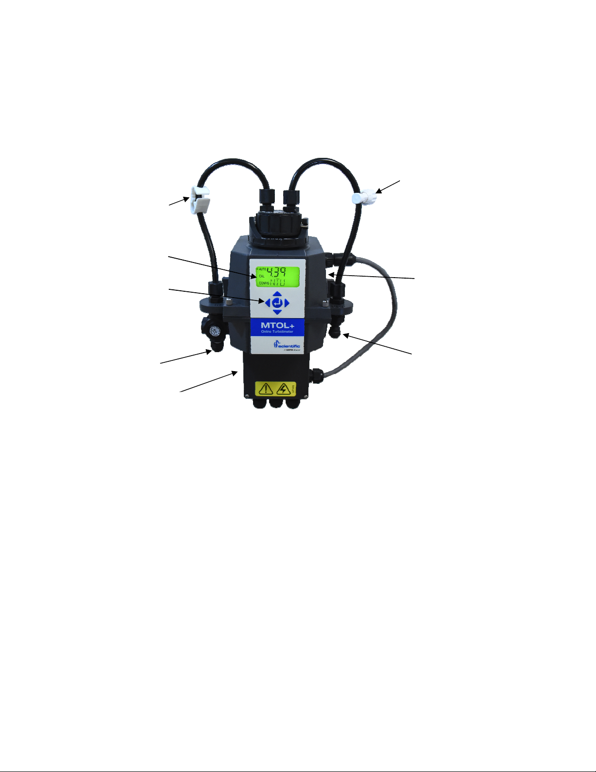
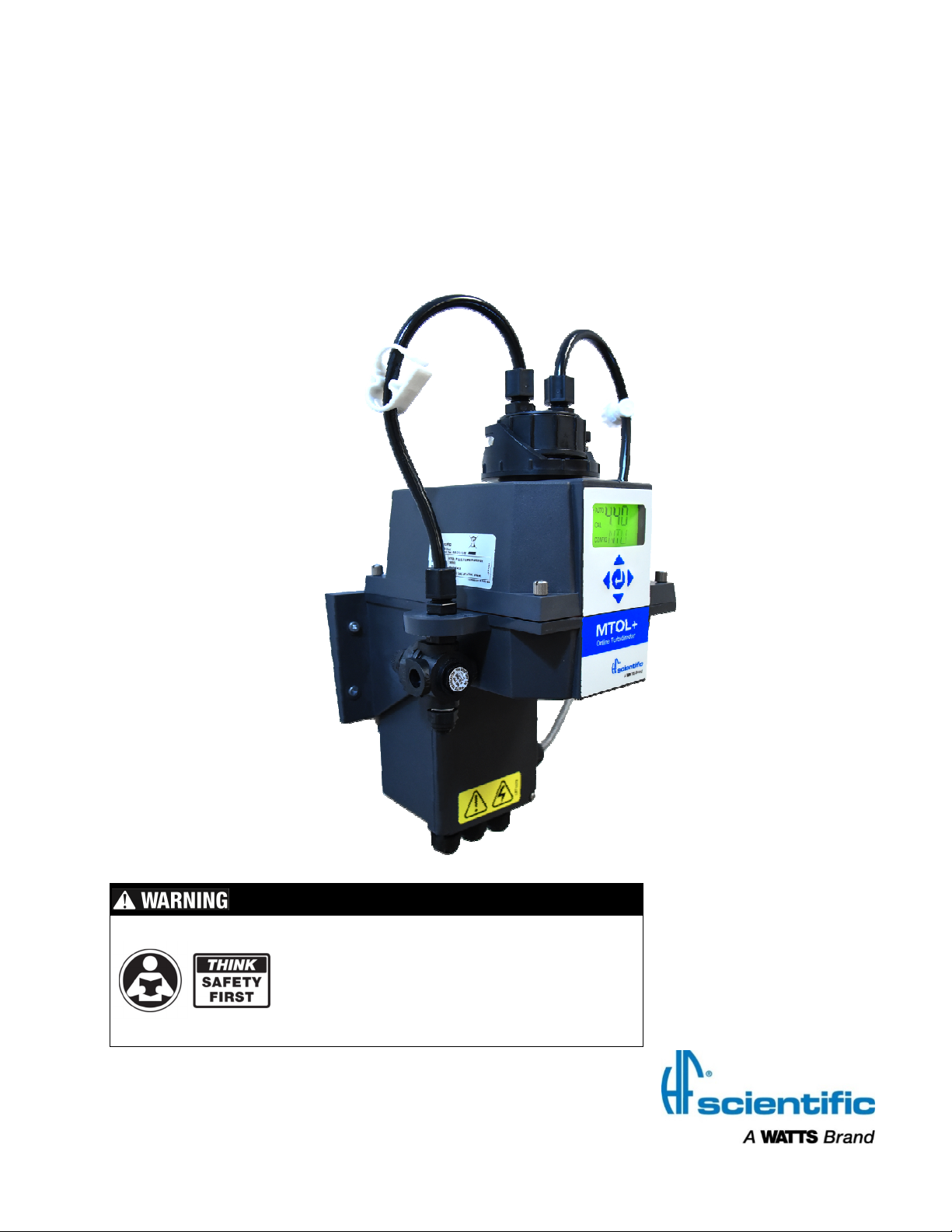
1.0 Overview
Shutoff Clamp
Display
Keypad
Water Inlet
Backpressure valve
USB Slot
Drain
Junction Box
1.1 The MTOL+ - Product Description
The MTOL+ process turbidimeter allows for the measurement of the turbidity of
process water on-line. The MTOL+ works by nephelometery; which means it
measures reflected light at 90° incident to the light beam. The white light MTOL+
(Model #28053) has been designed to meet the design criteria specified by the
US EPA 180.1 on turbidity measurement. The infrared MTOL+ (Model #28052)
was designed to meet the design criteria specified in ISO 7027 and DIN 27027
for the measurement of the turbidity of a sample. Both models have long life
lamps.
All models have ultrasonic cleaning. Refer to section 5.5 for more information.
A pressure regulator on the incoming line is a standard on all MTOL+ instruments
and will reduce pressures up to 7 bar (101.5 PSI) down to 1.03 bar (15 PSI).
The MTOL+ instruments are fully equipped with isolated 4-20mA, Modbus, two
alarms and ultrasonic cleaning. The only option is a flow alarm which must be
factory installed.
3
Page 10
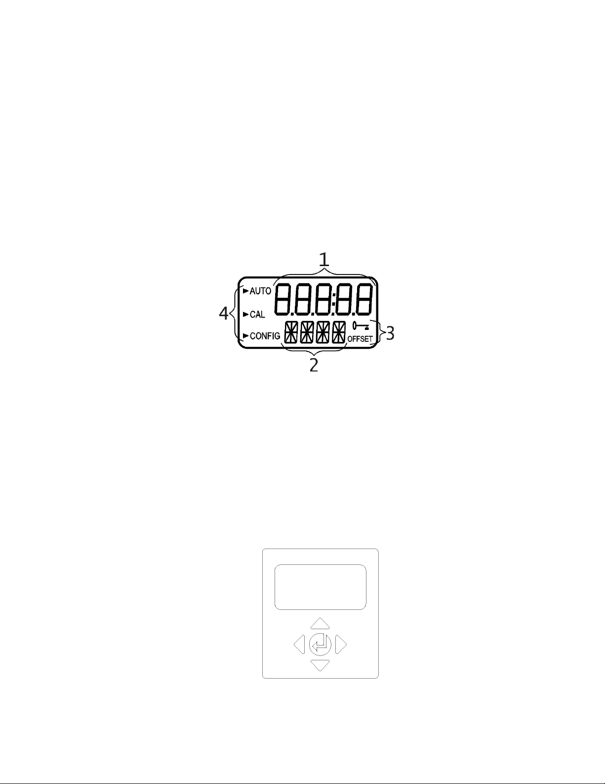
1.2 The Display
Figure 1 illustrates all the items that can appear on the display.
• The upper row of the display is used for reporting the turbidity levels and to
provide user guidance in the customer setting routine.
• The lower row of the display is used to communicate error messages and
provide user guidance.
• The display has two icons that are used to indicate the use of access code
and offset mode.
• In addition, mode arrows are used to indicate the current instrument
operating mode: AUTO (normal operation), CAL (calibration) and CONFIG
(configuration).
Figure 1 – Display used in the instrument.
All items used on the display are shown in this figure
1.3 The Touch Pad
Figure 2 illustrates the touch pad. The touch pad has five buttons arranged in
star pattern with a center button.
• Right and left ⊳ buttons allow scrolling forward and backward through
the menus
• Up and down buttons are used to change selections
• The center button is used to accept a change.
Figure 2: Touch Pad
4
Page 11
Item
Quantity
1.4 Vapor Purge
• The MTOL+ is equipped with a continuous Vapor Purge system.
• A replaceable desiccant pouch in the lower portion of the instrument dries the air.
System heat is used to warm the air. A fan inside the instrument continuously
circulates heated dry air around the optical well and the flow through cuvette.
This feature eliminates the need for a dry purge line.
The MTOL+ monitors the replaceable desiccant pouch condition
continuously. The LCD display will show DESC on the lower line in the event that the
desiccant pouch needs replacement. Replacement desiccant pouches are available
from HF scientific or the local representative (Part # 21555R). Refer to section 5.1
Replacing or installing the Desiccant Pouch.
The MTOL+ creates its own internal environment. In this controlled environment
condensation cannot form. The cuvette is essentially bathed in warm, dry air.
2.0 Unpacking and Inspection
The table below indicates the items in the turbidimeter shipment.
MTOL+ Turbidimeter with Flow Through Assembly
Field Terminal Box with Interconnect cable
Owner’s and User’s Manual
Desiccant Pack
Tubing Kit: 1-shutoff clamp
1-backpressure valve
2-connecting tubing with fittings for flow through assembly
Screwdriver to make electrical connections in junction box
USB Flash Drive (Including files for optional ranges and user manual)
Remove the instrument from the packing carton. Carefully inspect all
items to ensure that no visible damage has occurred during shipment. If the
items received do not match the order, please immediately contact the local
distributor or the HF scientific Customer Service department.
1
1
1
1
1
1
1
5
Page 12

3.0 Installation
The MTOL+ must be mounted and installed in a suitable location, plumbed to
the sample water source (section 3.34), and hard-wired to electrical power (section 3.4).
Installation MUST be performed by qualified technicians, including licensed electricians,
following all instructions, complying with all local, state, federal and other governmental
requirements, and with all building and construction codes and standards.
If you have any questions or are uncertain about proper site location, installation or
connection of the MTOL+, please contact customer service at HF scientific.
• Installation MUST be performed by qualified technicians, including licensed
electricians, following all instructions, complying with all local, state, federal and other
governmental requirements, and with all building and construction codes and standards.
• MTOL+ is electrically powered. ALWAYS take proper precautions to recognize,
evaluate, and control electricity hazards during installation, programming, use and
service/maintenance.
• Use ONLY with water free of corrosive chemicals or other hazardous substances.
• ALWAYS leak check plumbing connections following installation and on a regular
basis.
• MTOL+ MUST be installed in an area isolated from vibration, and not susceptible to
freezing or temperature extremes. Mount on any suitable vertical and flat surface that
can support the product’s weight.
• Keep installation and work area clean, well-lighted, free of clutter and distractions, and
accessible only by authorized personnel and workers.
• MTOL+ must be located in accessible and well-lighted area for use, servicing, repair or
replacement by authorized personnel.
6
Page 13

3.1 Site Selection
Choose a site that is accessible and well-lighted for use, servicing, repair
or replacement by authorized personnel.
• MTOL+ should be located and mounted within 2-3 meters (6 to10 ft) of
the sampling point to ensure a quick response time.
• Installation/mounting site must be isolated from vibration, and not
susceptible to freezing or temperature extremes.
• Site must have a suitable vertical and flat surface that can support the
product’s weight and service operations 5kg (10lbs).
• There should be 20 cm (8 in) free area above the instrument. This will
ensure enough room for calibration and cuvette maintenance.
• Site must allow for mounting MTOL+ with front display positioned at
eye level 1.4 to 2 meters (approximately 4.5 to 6.5 feet from floor).
• MTOL+ is designed to have the Junction Box cradled under the upper
portion of the instrument – Select a site with enough space for proper
configuration when mounted.
3.2 Mounting
Described is for installation to a concrete surface. If needed
contact HF scientific for instruction to install on other surfaces.
Tools required:
Appropriate screwdriver or driver gun.
Mounting Template – last page of this Manual.
Masking tape for attaching Mounting Template to wall.
Any tools required by wall anchor manufacturer if used.
Hardware required:
7
4 Mounting screws for instrument enclosure - M6 (¼”). Either use concrete
screws or use a wall anchors & the supplied screws.
2 Mounting screws for terminal junction box - M4 (#8). Either use concrete
screws or use a wall anchors & the supplied screws.
Page 14

1. Using masking tape, affix the mounting template to the vertical surface of
the selected mounting location and mark location for screws.
• The MTOL+ is designed for vertical wall mounting. If wall
mounting is not practical, the instrument can be mounted on any
suitable vertical, flat surface.
• Make sure that the mounting position is level.
2. The overall mounting dimensions of the MTOL+ are shown in Figure 3,
below. Measure to confirm that the mounting location has sufficient space
and that there is at least 20 cm (8 in) free area above the instrument when
mounted. This will ensure enough room for calibration and cuvette
maintenance.
3. Carefully remove the mounting template from the wall, keeping it in one
piece for future reference and use.
4. Install wall anchors (if needed) - Following manufacturer’s instructions for
the wall anchors, and using the mounting template as a guide, insert wall
anchors for each mounting position.
5. Mount the Junction Box First. The MTOL+ is designed to have the
Junction Box cradled under the upper portion of the instrument containing
the key pad and display.
a. Position the Junction Box of the MTOL+ to match the 2 lower wall
anchors.
b. Mount the Junction Box first by inserting the M4 (#8) screws
through the 2 inside the Junction Box. Use wall anchors as
needed.
Using the screwdriver, hand-tighten both screws, ensuring that the
Junction Box is firmly and securely attached.
6. Mount the upper key pad and display section. After securely mounting
the junction box, mount the upper portion of the MTOL+ so that the
junction box is cradled under the upper portion.
a. Position the upper portion of the MTOL+ to match the remaining
holes or wall anchors.
b. Insert M6 (1/4”) screws though the 4 tabs on the upper portion of
the MTOL+ and into the wall anchors.
c. Using the screwdriver or driver gun, to tighten the screws, ensuring
that the upper portion is firmly and securely attached.
8
7. Confirm that MTOL+ is securely mounted to wall (or vertical surface) and
positioned:
Page 15
• Within 2-3 meters (6 to10 ft) of the sampling point to ensure a quick
response time.
• Isolated from vibration, and not susceptible to freezing or temperature
extremes.
• Suitable vertical and flat surface that can support the product’s weight
5 kg (10lbs).
• 20 cm (8 in) free area above the instrument, allowing room for
calibration and cuvette maintenance.
• Front display should be positioned at eye level or a suitable level to
read and reach controls - approximately 1.4 Meters (4.5 feet) to 2
meters (6.5 feet) from floor.
• Confirm that the unit is level.
Turbidity Sensor
Junction Box
9
Figure 3: Mounting Dimensions of the Instrument
Page 16

3.3 Plumbing & Assembly
ONLY qualified personnel should perform plumbing
connections following all instructions, complying with all local, state,
federal and other governmental requirements, and with all building and
construction codes and standards.
MTOL+ requires very little head pressure to operate 6.9kPa (1 PSI).
The flow through cuvette is rated for a flow of 100ml/min. - 1 liter/min. (0.026-
0.26Gal/min).
The integral pressure regulator is rated for a MAXIMUM pressure of 7 bar
(101.5 PSI).
The MAXIMUM allowable fluid temperature is 50°C (122°F).
3.3.1 Initial Assembly
The IN and OUT tubes must be connected to the MTOL+ before the
system is connected to the sample water source and drain.
1. Identify the IN tube. This is the tube with the white ratcheting clamp.
2. Install the IN tube between the sensor mounting ear marked IN and the
flow head connection marked IN. Secure both ends tightly.
3. Identify the OUT tube. This is the tube with the rotary backpressure valve.
4. Install the OUT tube between the sensor mounting ear marked OUT and
the flow head connection marked OUT. Secure both ends tightly.
3.3.2 Connection of MTOL+ to System Plumbing
Requirements:
Use ¼ inch OD flexible tubing (polyethylene or polypropylene) for connecting
the MTOL+.
Use Opaque tubing if tubing may be exposed to
sunlight. This will help limit algae growth.
10
MTOL+ has push-to-connect fittings for water inlet and drain connections.
Page 17
WATER INLET
TUBING
DRAIN
TUBING CONNECTION
PRESSURE REGULATOR
SHUTOFF CLAMP
This clamp allows for shutting
off the intake flow during
cuvette maintenance. Press
down to restrict water flow.
Flow Through Cuvette
The flow through cuvette is
rated for a flow of 100ml/min 1liter/min. (0.026-0.26Gal/min).
BACKPRESSURE VALVE
This valve allows for an
adjustment to reduce bubble
formation. Turn clockwise to
increase backpressure.
The integral pressure regulator is
rated for a maximum pressure of 7
bar (101.5 PSI). The maximum
allowable fluid temperature is 50°C
(122°F).
CONNECTION
Use ¼” OD tubing with supplied
push-to-connect fitting.
Polyethylene or polypropylene
are recommended tubing types.
Use ¼” OD tubing with supplied
push-to-connect fitting. Do not
reintroduce drain sample back
into the process stream
Figure 4 Instrument parts identification
11
Page 18

3.3.3 Connecting the drain:
a. MTOL+ drain tubing MUST be routed to a suitable
sanitary sewer drain. Wetted materials are not FDA approved.
DO NOT return the drain sample or any water run through MTOL+
into the process stream or into any potable water supply.
b. Select a length of ¼ inch OD flexible tubing (Polyethylene or
polypropylene) long enough to directly connect the MTOL+ drain
connection point to a suitable sanitary sewer drain. Avoid
unnecessary bends or sags in tubing. Make sure there are no
kinks, twists, breaks, or damage of any kind in tubing.
c. Using a sharp utility knife, cut the end of the tubing square.
Remove any burrs or sharp edges before inserting into fitting.
d. Place a piece of tape ½ inch from end of tube to indicate how far
the tube should be inserted.
e. Push the tube into the Quick-Connect fitting on the right facing side
of the MTOL+, as shown in Figure 4.
f. Check to confirm that tube is pushed fully against the tube stop.
Gently but firmly pull on the tube to check that it is secure.
g. Connect the other end of the tube to a suitable sanitary drain or
trench following proper plumbing techniques applicable to your
facility and configuration.
3.3.4 Connecting the water intake:
a. Use MTOL+ ONLY with water. Connect water intake
ONLY to water free of corrosive chemicals or other hazardous
substances.
HF scientific accepts no responsibility for damage caused by the
introduction of vapors, fluids or other materials into the instrument
process stream which is not compatible with the instrument's
wetted materials. A list of the wetted materials can be found in the
specifications on page 2 of this manual.
b. Select a length of ¼ inch OD flexible tubing (Polyethylene or
polypropylene) long enough to directly connect the MTOL+ water
inlet connection point to water sampling point. Avoid unnecessary
bends or sags in tubing. Make sure there are no kinks, twists,
breaks, or damage of any kind in tubing.
12
Page 19

c. Using a sharp utility knife, cut the end of the tubing square.
Remove any burrs or sharp edges before inserting into fitting.
d. Place a piece of tape ½ inch from end of tube to indicate how far
the tube should be inserted.
e. Push the tube into the Quick-Connect fitting on the left facing side
of the MTOL+, as shown in Figure 4.
f. Check to confirm that tube is pushed fully against the tube stop.
Gently but firmly pull on the tube to check that it is secure.
g. Connect the other end of the tube to the water sample source
following proper plumbing techniques applicable to your facility and
configuration.
After completing water inlet and drain connections, check all tubing
and connections for any leaks, weeping, breaks or defects of any
kind. Repair/replace as needed.
13
Page 20
3.4 Electrical Connections
• MTOL+ is electrically powered. Installation MUST be performed by
licensed electrician following all instructions and comply with all local,
state, federal and other governmental requirements, and with all building
and construction codes and standards for all electrical connections and for
installation of electrical connections to and between the instrument and
any peripheral devices.
• ALWAYS take proper precautions to recognize, evaluate, and control
electricity hazards during installation, programming, use and
service/maintenance.
Requirements:
• The MTOL+ is equipped with a 100-240 VAC, 47-63 Hz switching power
supply. BEFORE installing, verify that the line voltage falls within
these specifications.
• A breaker or method of disconnecting power must be placed within 2
meters (6 feet) of the MTOL+.
• While making connections, refer to Figure 5. The MTOL+ is not supplied
with a power cord.
• All of the electrical connections to the instrument are made through the
MTOL+ Junction Box (see Figure 5), which should be located directly
under the sensor portion of the instrument.
• The power cable glands will accept cable diameters from 5.8mm (.230 in)
up to 10 mm (.395 in.).
• All terminals are designed to accept wires in the range of 12-30 AWG. All
wires should be stripped to a length of 6 mm (¼ in).
• A strain relief strap is provided to reduce tension on the power terminals.
14
Page 21

• The connections are labeled within the terminal box and are selfdescriptive (see Figure 5).
• Plugs are inserted into the alarm and 4-20mA/RS-485 cable glands when
shipped, to ensure a watertight seal. These plugs should be removed and
discarded when cabling to either of these connections.
• Maintain watertight seal. It is the owner’s and installer’s responsibility to
assure that the watertight seal is maintained after the terminal box has
been wired for operation. Failure to properly tighten any of the cable
glands around a cable or plug can create an electrical shock/electrocution
hazard.
3.4.1 Electrical Power Connection:
Make all connections at Junction Box and securely close BEFORE
making connections to power source and energizing MTOL+.
ONLY licensed electrician should perform installation. ALWAYS
take proper precautions to recognize, evaluate, and control electricity
hazards.
a. First, make sure that MTOL+ is completely de-energized and
disconnected from all power.
b. Perform required LOCK OUT/TAG OUT of electrical power.
c. Confirm that a breaker or method of disconnecting power is located
within 2 meters (6 feet) of the MTOL+.
d. All of the electrical connections to the instrument are made through
the MTOL+ Junction Box (see Figure 5), which should be located
directly under the upper portion of the instrument.
e. Carefully open the MTOL+ Junction Box (see Figure 5) by removing
the four cover screws.
f. With the Junction Box cover removed, the connections are visible
as shown in Figure 5.
g. The power cable glands will accept cable diameters from 5.8mm
(.230 in) up to 10 mm (.395 in.). All terminals are designed to
accept wires in the range of 12-30 AWG.
15
Page 22

h. Obtain and cut proper wires to make connections for your specific
installation and facility. All wires should be stripped to a length of 6
mm (¼ in).
i. The connections are labeled within the terminal box and are self-
descriptive (see Figure 5).
j. Make connections following all local, state, federal and other
governmental requirements, and all building and construction codes
and standards for all electrical connections.
Earth or Ground wire must be connected to terminal on the MTOL+ marked “G”
k. A strain relief strap is provided to reduce tension on the power
terminals. Pull this tight after completing the connections.
l. Perform all checks necessary to confirm proper wiring and safe
electrical connection.
3.4.2 Terminal Block (P1) Connections:
Shut off and disconnect all electrical power BEFORE making or
changing any connections. The terminal block (P1) is located close to the
power connection.
The terminal block for RS-485 (Modbus), 4-20 mA and Alarms has spring
loaded connections.
To open the connection, insert a 3mm (1/8 in) flat blade screwdriver into
the slot right above the electrical connection. Pulling up slightly on the
screwdriver opens the terminal block connection. Removing the
screwdriver tightens the connection.
There are two stacked rows of connections which are labeled on the PCB.
The alarm connections are on the upper row. The RS-485 and 4-20mA
are on the lower row.
.
16
These connections are rated for a wire size from 12-28 AWG, either solid
or stranded.
a. Alarm and I/O Connections.
• The Alarm 1 and Alarm 2 relays are mechanical relays rated at 120-240
VAC 2A.
• Note that the relays are labeled NO (Normally Open), NC (Normally
Closed) and C (Common).
• The normal condition is with power applied to the MTOL+ and in a nonalarm condition. Operation of these alarms is covered in section 4.2.4
Configuring the Alarms.
Page 23

• Connections are labeled beneath the large terminal block. These
connections are on the upper row.
b. RS-485/Modbus Connection
• The RS-485 half-duplex (2-wire) digital interface operates with differential
levels that are not susceptible to electrical interferences. Cable lengths up
to 900 meters (3000 ft.) can be implemented.
• The last device on each bus may require terminating with a 120-ohm
resistor to eliminate signal reflection on the line.
• Do not run RS-485 cables in the same conduit as power.
• Ensure that power is disconnected prior to making connections to present
damage to the instrument.
• Connections are labeled beneath the large terminal block. These
connections are on the left side on the lower row.
c. 4-20 mA Connection:
Make sure the MTOL+ is disconnected and not powered BEFORE
connecting the 4-20 mA.
• The 4-20 mA output is driven by a 24 VDC power source and can drive
recorder loads up to 1000 ohms.
• This 4-20 mA output is isolated from line power and earth ground.
• Do not run 4-20 mA cables in the same conduit as power.
• Connections are labeled beneath the large terminal block. These
connections are on the right side on the lower row.
• Operation of this output is covered in section 4.2.1 Setting the 4-20 mA.
17
Page 24

3.4.3 Closing the Junction Box.
Maintain watertight seal. Always make sure that the Junction
Box cover is firmly in place and securely closed. Water infiltration
can create electric shock/electrocution hazard and will damage
equipment.
• Securely close the Junction Box by replacing the cover and all four
cover screws.
Power Connection
Terminal Block (P1)
Alarm & I/O Connections
Figure 5: Electrical Connections for the MTOL+
---------------------------------------------------
18
Figure 6: Electrical Connections on Terminal Block (P1)
Page 25

4.0 Setup, Configuration and Calibration
Prior to use for the first time, the supplied desiccant pouch will need to be
installed.
Refer to section 5.1 Replacing or Installing the Desiccant Pouch.
Before using your MTOL+, you will need to familiarize yourself with the instrument’s
operating modes and functions, and perform some set up, configuration and calibration.
• The MTOL+ allows for the measurement of the turbidity of process water
on-line. The turbidity of the process water is usually reported in
Nephelometric Turbidity Units (NTU), but may be reported in Formazine
Nephelometric Units (FNU).
• Readings above 100 NTU are outside the pre-configured range of this
instrument. Readings above 110 NTU will cause the display to flash
indicating an over range condition.
• For a unit calibrated in the 0-10 NTU Range… Readings above 10 NTU
are outside range of this instrument. Readings above 11 NTU will cause
the display to flash indicating an over range condition.
• For a unit calibrated in the 0-1000 NTU Range… Readings above 1000
NTU are outside the range of this instrument. Readings above 1100 NTU
will cause the display to flash indicating an over range condition.
• During normal operation, the instrument will have the arrow beside AUTO
highlighted with the current scale displayed on the lower row of the display
and the measured reading on the upper row of the display (see illustration
below).
4.1 Modes of Operation
There are four modes of operation, AUTO, CAL, CONFIG & HOLD. To
change between AUTO, CAL, HOLD and CONFIG use the and then
the button to select.
a. AUTO mode is the normal automatic operation. This is the default
mode when power is applied or restored. The other three modes of
operation are limited to 15 minutes with no key presses after which
they will return to AUTO made operation.
19
Page 26

b. CAL is the calibration mode. All reading outputs and alarms are
held while in this mode of operation. The instrument was calibrated
and tested prior to leaving the factory. Therefore, it is possible to
use the instrument directly out of the box. Under normal conditions,
re-calibration is required once every three months. Quarterly
calibration ensures performance within accuracy specifications.
• Enter the CAL mode of the instrument by pressing the or
buttons until the arrow beside CAL is illuminated, then
press the
• Use the and buttons to move forward and backward
through the calibration points.
• To exit the CAL mode start a calibration point after the
countdown starts press or . When the screen shows
ABRT press the
• Relay contacts and the 4-20mA will be frozen (held at the
current state) while the instrument is in the calibration mode.
• While in the calibration mode, the instrument has a time-out
feature that automatically returns the system operation to the
AUTO mode after a fifteen (15) minute period of inactivity.
c. CONFIG is the configuration mode. In CONFIG mode, you can
customize the instrument according to needs and preferred
operation at any time during normal operation. The CONFIG mode
has been split into sub-menus to facilitate instrument configuration.
This is also where logged files and calibration logs can be
downloaded and where new software, when available, can be
uploaded.
button.
button.
20
• Enter the CONFIG mode of the instrument by pressing the
or buttons until the arrow beside CONFIG is
illuminated, then press the
• To exit the CONFIG mode at any time, press the
• The ⊳ and buttons are used to move forward and
backward through the menus.
• All reading outputs and alarms are held while in this mode of
operation. Relay contacts and the 4-20mA will be frozen
(held at the current state) while the instrument is in the
configuration mode. While in the configuration mode, the
instrument has a time-out feature that automatically returns
the system operation to the AUTO mode after a fifteen (15)
minute period.
button.
button.
Page 27

• Shown below is a Flow Chart depicting the options under the
configuration operation:
d. HOLD mode is intended for servicing the instrument and holds the
outputs and alarms. During this mode the 4-20mA and alarms are
frozen. This mode can be used to ensure that no changes
accidentally are made to the instrument. This mode will time out
after 15 minutes and revert back to AUTO mode.
• Enter the HOLD mode of the instrument by pressing the
or buttons until the arrow beside HOLD is illuminated,
then press the
Figure 6 MTOL+ Flow Chart
button.
• Once selected the letters above will change from OFF to
21
ON.
Page 28

• The HOLD mode can be used during any maintenance
functions such as changing the cuvette or desiccant without
affecting alarms or the 4-20mA output signals.
• CAL, CONFIG & HOLD are limited to 15 minutes after which
time they automatically revert to AUTO mode.
4.2 Configuring the MTOL+
The MTOL+ has been designed to provide the ability to customize the
instrument according to needs at any time during normal operation. The
CONFIG mode has been split into sub-menus to facilitate instrument
configuration. This section describes how to use each of the sub-menus
to configure the instrument. In the sections below each sub-menu under
the CONFIG mode is discussed in the order that they are reached by
circling through the CONFIG mode, as identified in the flow chart located
previously.
Turn Power “ON:” After confirming that the MTOL+ is safely and
properly mounted, connected and installed, turn the instrument ON by
connecting or turning on the power.
22
To enter the CONFIG Mode: Enter the CONFIG mode by pressing the
or buttons until the arrow beside CONFIG is illuminated, then press the
button.
To exit the CONFIG Mode: To exit the CONFIG mode at any time, press
the
button. Use the ⊳ and buttons to move forward and backward
through the menus.
4.2.1 Configuring the 4-20mA Output
The 4mA can be set higher than the 20mA level to invert
the output current if required. This may be required to
control a dosing pump.
Page 29

• See 4.2.13 to calibrate the 4-20mA output.
Enable 4-20mA – Enable or Disable 4-20mA Output: Enter the
CONFIG mode by pressing the and buttons until the arrow beside
CONFIG is displayed, then press the
appear only if the 4-20mA is enabled. If disabled skip down to 4.2.2
• This will be the first menu shown unless the option flow switch was
ordered. Use the or buttons to select whether the 4-20mA will be On
or OFF. Press the button to accept the setting and move to the next
menu or the
button to exit and return to AUTO.
button. The next three menus
Setting 4mA - Setting the 4mA:
• The first prompt will be the turbidity limit assigned to the 4mA output level:
• Select the turbidity level to assign to the 4MA using the and buttons.
The factory setting is 0.02 NTU.
Setting 20mA - Setting the 20mA:
• Next, select the turbidity level to assign to the 20mA output level using the
and buttons. The factory setting is 100.00 NTU.
23
• 20MA is displayed on the lower row of the LCD display. Select the
turbidity level to assign to the 20MA using the and buttons.
• Once the desired level has been set, press the button to accept the
setting and move to the next menu or the
button to exit and return to
Page 30

AUTO.
Error Level - Configuring the Error Level:
• In case of an error in the MTOL+, the 4-20 mA reading can be used to
indicate a problem by sending the current to either 4.00 mA, 2.00 mA.
0.00 mA, or OFF.
• The factory default setting is OFF and the 4-20mA is unaffected by any
error condition.
• To change the Error Level, enter the CONFIG mode by pressing the
and buttons until the arrow beside CONFIG is illuminated, then press
the
button.
• Press the button to move to the next menu until ERLV is displayed.
• Select the desired ERLV by using the and buttons then press the
button to accept the setting and move to the next menu or the
exit and return to AUTO.
4.2.2 Baud Rate - Selecting the RS–485 Baud Rate
• Select the desired baud rate (1200, 2400, 4800, 9600, or 19200) for
operation of the I/O port.
To change the Baud Rate: Enter the CONFIG mode by pressing the
and buttons until the arrow beside CONFIG is illuminated, then press
the
button.
• Press the button to move to the next menu until BAUD is displayed.
• Select the desired BAUD rate by pressing the or buttons to change
the displayed baud rate.
button to
24
Page 31

• Press the button to accept the setting and move to the next menu or the
button to exit and return to AUTO.
4.2.3 Modbus Address – Address Selection
• Select the Modbus address of the MTOL+ from 1 to 255. For more
information on Modbus refer to the Modbus Manuals Cat #29291. This
manual can also be downloaded for no charge at www.hfscientic.com.
To change the Modbus Address: Enter the CONFIG mode by pressing
the and buttons until the arrow beside CONFIG is illuminated, then
press the
• Press the button to move to the next menu until ADDR is displayed.
• Select the address using or buttons.
button.
• Press the button to accept the setting and move to the next menu or the
button to exit and return to AUTO.
4.2.4 Configuring the Alarms
• Two relays are provided that are designed to operate as two independent
programmable alarms. Three types of information must be input to fully
program each alarm:
a. The alarm function (HI, LO, OFF or Error)
b. The alarm set point (level at which the alarm activates)
c. The delay time for the alarm: The time that the set point must be
exceeded prior to alarm activation and the time before resetting the alarm
(prevents chatter in the relay).
a. Alarm Function: The alarms can either be turned OFF or
programmed to operate in one of three different manners:
25
• HI alarm: the relay changes state when the measured turbidity level
is higher than the programmed alarm level for a prescribed time.
• LO alarm: the relay changes state when the measured turbidity level
is lower than the programmed alarm level for a prescribed time.
• Error: the relay changes state when a system error occurs. If a
Page 32

system error occurs a message will appear on the lower row of the
screen describing the problem.
b. Alarm Set Point: The level at which an alarm activates is called
the alarm set point. On the instrument, the alarm set point is
designated as “S/P”. The set point is adjustable to any valid
turbidity level over the range of the instrument in steps of 0.01 NTU.
c. Alarm Delay Time: The alarm delay times are used to prevent
tripping the alarm when the turbidity level is close to the set point.
The function of the delay times is as follows:
• Delay On: The turbidity level must exceed the alarm set point
continuously for at least this number of seconds before the alarm
activates.
If the “delay on” time is set at 5 seconds and the process
turbidity exceeds the set point continuously for only 4
seconds, the alarm will not be activated. However, if
process turbidity exceeds the set point continuously for 5
seconds or more; the instrument will activate the alarm.
• Delay Off: The turbidity level must not exceed the alarm set point
continuously for at least this number of seconds prior to
deactivation of the alarm.
If the “delay off” time is set to 5 seconds and the process has
exited out of the alarm condition, the alarm will be reset only
if the process is out of the alarm condition for a continuous 5
seconds. Otherwise, the instrument will still signal an alarm
condition.
4.2.4.1 Alarm 1 - Configuring Alarm 1
Alarm 1 Function: The ALM1 is displayed and the display
indicates the current function of Alarm 1 (HI, LO, OFF or Error).
• Use the or buttons to cycle through and select the desired
function.
• Press the button to accept it and move to the next menu.
• If the alarm was turned OFF a prompt will appear to set up Alarm 2
(go to section 4.2.10.2). If, on the other hand, one of the other HI
or LO was selected, a prompt will appear to set the delay times.
Alarm 1 Set Point: Set Point is indicated by “S/P” shown on the
lower row of the display, and is used to select the set point for this
alarm.
• Select the desired alarm level by using the and buttons.
26
Page 33

• Once the desired set point has been set, press the button to
accept it and move to the next menu.
• Alarm 1 Delay Times:
1. Delay On: The following display will appear to allow you to
select the number of seconds currently set for the “delay on”
time.
• The current selected number of seconds will be shown. Select
the desired number of seconds for the “delay on” time for this
alarm using the and buttons. Once the desired delay time
has been set, press the button to accept it and move to the
next menu.
2. Delay Off: Next, the following display will appear to select the
number of seconds currently set for the “delay off” time.
• The current selected number of seconds will be shown. Select
the desired delay off time for this alarm using the and
buttons. Once the desired delay time has been set, press the
button to accept it and move to the next menu.
• After the settings for Alarm 1 have been completed, prompts will
allow for the set-up of the information on Alarm 2.
4.2.4.2 Alarm 2 - Configuring Alarm 2
Repeat the procedure listed in section 4.2.10.1 to set up the
parameters for alarm 2.
27
Page 34

4.2.5 Offset – Offset Reading Adjustment
• A reading offset can be made to allow for the MTOL+ to agree with
another instrument if desired.
• This range is limited to ± 1NTU.
• For more information refer to section 4.3.6.
To change the Offset: Enter the CONFIG mode by pressing the and
buttons until the arrow beside CONFIG is illuminated, then press the
button.
• Press the button to move to the next menu until OFST is displayed.
• Select the offset using the or buttons to turn the function On.
• When the OFST is turned ON it will stay illuminated in AUTO
as a reminder that it is being used.
• Select the offset using the or buttons.
• Press the button to accept the setting and move to the next menu or the
button to exit and return to AUTO.
4.2.6 Access Code - Setting Security
• The MTOL+ is equipped with a security access feature that can be
activated. If this option is turned ON, the user is required to input an
access code into the instrument to get to any mode other than AUTO. A
three digit code is used.
• HF Scientific highly recommends the use of a security access code
in order to help prevent unauthorized access to the system and data.
• When the CODE is turned On the icon will be illuminated in
AUTO as a reminder that an access code is being used.
Setting Security on/off: Enter the CONFIG mode by pressing the and
buttons until the arrow beside CONFIG is illuminated, then press the
button.
28
• Press the button to move to the next menu until CODE is displayed.
• Use the or buttons to select the setting. (On or OFF).
Page 35

Setting Security Code: With the security feature enabled (“ON”), press
the button. The screen shown in the illustration below will appear:
• The 3 digit security code is set one digit at a time. Using the or
buttons, select each digit. The flashing digit is the number that is currently
being adjusted.
• Once a digit is selected, press the button to move on to the next
number.
• Now enter the second number in the code. Proceed as with the first
number followed by .
• Repeat the process for the third, and finish with the button.
• When the code is turned On, the code must be used to exit
AUTO
• If a valid access code has been selected, the instrument will be directed to
the calibration mode. If the wrong access code is selected, the instrument
will return to the AUTO mode.
• If the access code was set On from AUTO press or . The next screen
will allow entering the three digit code into the instrument. The security
code is entered one digit at a time using the or to select the digit and
to advance to the next digit. Accept the code by pressing the
4.2.7 Signal Averaging - Setting Speed of Response
• The averaging can be used to smooth out the response to spikes or
unstable readings that may be caused by bubbles or small debris.
• The response is done by averaging readings. Both displayed and output
values of NTU are affected in this menu. The default setting is 1; however,
button.
29
Page 36

up to 60 readings can be averaged.
• To avoid reading air and other anomalies, select a higher averaging.
• Select the lowest averaging where monitoring of rapid changes is needed.
These are one second intervals so the maximum averaging is 60 seconds.
• The factory default is 10.
To change the Averaging: Enter the CONFIG mode by pressing the
and buttons until the arrow beside CONFIG is illuminated, then press
the
button.
• Press the button to move to the next menu until RESP is displayed.
• Use the or buttons to select the setting for the speed of response
desired.
• Press the button to accept the setting and move to the next menu or the
button to exit and return to AUTO.
4.2.8 Display Resolution - Setting Resolution
• The instrument is equipped with the ability to display several levels of
resolution. The instrument can display up to four digits to the right of the
decimal place for turbidity readings below 10 NTU. The default setting is
000.00 If the last digit or two is not stable, adjust the resolution to hide
these insignificant digits.
To change the Resolution: Enter the CONFIG mode by pressing the
or buttons until the arrow beside CONFIG is illuminated, then press the
button.
• Press the button to move to the next menu until RES is displayed, then
press the
• Change the resolution by pressing the or button.
• When the desired digit resolution has been selected, press the button to
accept it and move to the next menu or the
AUTO.
button.
button to exit and return to
30
Page 37

4.2.9 LCD Brightness - Setting the LCD backlight brightness
• The LCD backlight brightness may need to be adjusted. This is of
particular interest if multiple instruments are located in the same area and
it is desired for the entire group to have the same appearance. Ten levels
are available. The default brightness is 8.
To adjust Backlight Brightness: Enter the CONFIG mode by pressing
the and buttons until the arrow beside CONFIG is illuminated, then
press the
• Press the button to move to the next menu until BRT is displayed.
• Change the brightness by pressing the or button.
button.
• When the desired brightness has been selected, press the button to
accept it and move to the next menu or the
AUTO.
4.2.10 Display Units - Setting Displayed Units
• The most common unit is NTU (Nephelometric Turbidity Units) however
the instrument can display in FNU (Formazine Nephelometric Units).
• All instruments are shipped from the factory set in NTU mode.
Setting/Changing Units: Enter the CONFIG mode by pressing the
and buttons until the arrow beside CONFIG is illuminated, then press
the
button.
• Press the button to move to the next menu until UNIT is displayed.
• Use the or buttons to select the setting NTU or FNU.
• Press the button to accept it and move to the next menu or the
button to exit and return to
31
Page 38

button to exit and return to AUTO.
4.2.11 Ultrasonic Cleaning - Cleaning Function
• This allows for a selection menu to turn off the ultrasonic cleaning
function if desired. The default mode is On.
Setting the ultrasonic cleaning: Enter the CONFIG mode by pressing
the and buttons until the arrow beside CONFIG is illuminated, then
press the
• Press the button to move to the next menu until CLN is displayed.
• Select On or OFF using the and buttons.
button.
• Press the button to accept I the setting and move to the next menu or
the
button to exit and return to AUTO.
4.2.12 Modbus Parity & Modbus Stop Bits - RS485 Parameters
• These two menus will be used to set the balance of the RS-485
parameters.
• The default is no Parity (nOnE), 1 Stop Bit.
Modbus Parity – Setting the Modbus Parity: Enter the CONFIG mode
by pressing the and buttons until the arrow beside CONFIG is
illuminated, then press the
• Press the button to move to the next menu until PRTY is displayed.
• Make selections using the and buttons
• Press the button to accept it and move to the setting stop bits
button.
32
Modbus Stop Bits – Setting the Modbus Stop Bits: Enter the CONFIG
mode by pressing the and buttons until the arrow beside CONFIG is
illuminated, then press the
button.
Page 39

• Press the button to move to the next menu until STOP is displayed.
• Make selections using the and buttons
• Press the button to accept it and move to the next menu or the
button to exit and return to AUTO.
4.2.13 4mA and 20mA Adjustment
• If the 4-20 mA setting is turned On, two menus will appear one for each 4
and 20mA adjustment.
4mA Adjustment:
• The first menu outputs a constant 4mA while allowing for a small amount
of adjustment. This adjustment will allow the operator to make the
MTOL+ agree with a PLC or SCADA system. The adjustment limits are ±
200 counts or about ± 0.2 mA.
• This setting will be slightly different on each instrument as
each MTOL+ will be factory set to 4.00mA. Press the button when
adjustments are complete to save this setting and move on to the 20mA
adjustment.
Setting the 4mA Levels: Enter the CONFIG mode by pressing the
and buttons until the arrow beside CONFIG is illuminated, then press
the
button.
33
• Press the button to move to the next menu until 4MA is displayed.
• Adjust setting using the and buttons.
• Press the button when adjustments are complete to save this setting
and move on to the 20mA adjustment.
20mA Adjustment:
• This menu operates similar to the previous menu. This menu outputs a
constant 20 mA while allowing for a small amount of adjustment. The
adjustment limits are ± 1000 counts or about ± 1 mA.
Page 40

• This setting will be slightly different on each instrument as each MTOL+
will be factory set to 20.00mA.
Setting the 20mA Levels: Enter the CONFIG mode by pressing the
and buttons until the arrow beside CONFIG is illuminated, then press
the
button.
• Press the button to move to the next menu until 20MA is displayed.
• Adjust setting using the and buttons.
• Press the button to accept the setting and move to the next menu or the
button to exit and return to AUTO.
4.2.14 Instrument ID – Instrument Unique Number Identification
• This menu provides the instrument with a unique ID up to 4 digits. This ID
can be used when logged data is downloaded. This enables the data to be
associated with a particular instrument or location.
Setting the instrument ID: Enter the CONFIG mode by pressing the
and buttons until the arrow beside CONFIG is illuminated, then press
the
button.
• Press the button to move to the next menu until ID is displayed.
• Use the and buttons to select the value of the first number. Use the
to select the next number and repeat the process for all numbers. Scroll
through the numbers to the next menu.
4.2.15 Logging Interval – Setting the interval for logged files
• This menu determines how often readings are logged. The setting is in
minutes. This can be set from 1 minute to 60 minutes.
34
Setting the logging interval: Enter the CONFIG mode by pressing the
Page 41

and buttons until the arrow beside CONFIG is illuminated, then press
the
button.
• Press the button to move to the next menu until INVL is displayed.
• The value can be adjusted by using the and buttons.
• Once the value is set, press the button to accept it and move to the next
menu or the
4.2.16 Download Logged Files – Select to Download
• This menu is used to download CSV files to a flash drive. The selections
are No download (NO), Calibration file only (CAL), All Files (ALL) or
individual month (Jan, Feb…). Once the data stick is inserted in the USB
slot on the right side of the instrument push the
is inserted you will get an Error (Err). See section 5.4.2 File Downloads
for more information. The upper display will flash while the download is
taking place and show dOnE when complete.
Setting the data download: Enter the CONFIG mode by pressing the
and buttons until the arrow beside CONFIG is illuminated, then press
the
button.
• Press the button to move to the next menu until DOWN is displayed.
• The selection can be adjusted by using the and buttons.
button to exit and return to AUTO.
button. If no data stick
35
• Once the selection is made press the button to accept it and move to
the next menu or the
4.2.17 Date and Time – Setting of Instrument Time & Date
• The MTOL+ has a displayed date (month / day / year) and time (hour /
minute / Daylight Savings) that must be set upon initial installation/setup.
The next five menus are used for this setup.
Setting Month: Enter the CONFIG mode by pressing the and
buttons until the arrow beside CONFIG is illuminated, then press the
button.
• Press the button to move to the next menu until MNTH is displayed,
button to exit and return to AUTO.
Page 42

then press the
• Change the month by pressing the or button.
• When the desired month has been selected, press the button to accept
it and move to the next menu or the
Setting Day: Enter the CONFIG mode by pressing the and buttons
until the arrow beside CONFIG is illuminated, then press the
• Press the button to move to the next menu until DAY is displayed, then
press the
• Change the day by pressing the or button.
button.
button.
button to exit and return to AUTO.
button.
• When the desired day has been selected, press the button to accept it
and move to the next menu or the
Setting Year: Enter the CONFIG mode by pressing the and buttons
until the arrow beside CONFIG is illuminated, then press the
• Press the button to move to the next menu until YEAR is displayed,
then press the
• Change the year by pressing the or button.
•
button.
button to exit and return to AUTO.
button.
36
• When the desired year has been selected, press the button to accept it
Page 43

and move to the next menu or the
Setting Hour: Enter the CONFIG mode by pressing the and buttons
until the arrow beside CONFIG is illuminated, then press the
• Press the button to move to the next menu until HOUR is displayed,
then press the
• Change the hour by pressing the or button.
• When the desired hour has been selected, press the button to accept it
and move to the next menu or the
button.
button to exit and return to AUTO.
button.
button to exit and return to AUTO.
Setting Minute: Enter the CONFIG mode by pressing the and
buttons until the arrow beside CONFIG is illuminated, then press the
button.
• Press the button to move to the next menu until MIN is displayed, then
press the
• Change the minute by pressing the or button.
• When the desired minute has been selected, press the button to accept
it and move to the next menu or the
Daylight Savings Time: DST is valid for use in the USA, Canada, and
other countries or locations that follow the US Energy Savings Act of
2005.
button.
button to exit and return to AUTO.
37
• Enter the CONFIG mode by pressing the and buttons until the arrow
beside CONFIG is illuminated, then press the
• Press the button to move to the next menu until DST is displayed, then
button.
Page 44

press the
• Change the Daylight Savings Time by pressing the or button until
ON is displayed.
• Press the button to accept it and move to the next menu or the
button to exit and return to AUTO.
4.2.18 Update Software - Install Latest Software or Change Range
• Enter the CONFIG mode by pressing the and buttons until the arrow
beside CONFIG is illuminated, then press the
• Press the button to move to the next menu until UPDT is displayed,
then press the
• The software version can be determined by pressing and holding down
the and buttons for about 1 second. The first number shown is the
version and second number displayed is the model number. This can be
performed anytime during AUTO Mode.
• Software updates can only be made if a USB flash drive is installed with a
newer version of software than the one currently installed in the MTOL+. If
either a flash drive is not installed or a newer version of software is not
detected the following screen will appear.
• Range changes can be made with either the current or later versions.
These other ranges were included on a flash drive included with the
instrument when new.
• Once a flash drive with valid files are found, select the desired range to
update using the and buttons.
button.
button.
button.
38
Page 45

• While the system is updating, the word “busy” appears as it performs a
self-check of the software installation.
• If the MTOL+ finds a flash drive with a previous version of software it will
show the word FILE. You will need an updated file on the flash drive.
• Once installed the system will automatically turn off and restart. The entire
process takes about 60 seconds to complete.
Be certain to check the configuration as changes may have taken
place either with new software or a new range.
39
Page 46

4.3 Calibrating the MTOL+, CAL Mode
• The instrument was calibrated for the 0-100 NTU range and tested prior to
leaving the factory. Therefore, it is possible to use the instrument directly
out of the box. Under normal conditions, re-calibration is required once
every three months. Quarterly calibration ensures performance within
accuracy specifications.
The EPA and ISO recommend that on-line turbidimeters be
calibrated with a primary standard at least once every three
months if they are to be used for reporting purposes.
• Relay contacts and the 4-20mA will be frozen (held at the current state)
while the instrument is in the calibration mode. While in the calibration
mode, the instrument has a time-out feature that automatically returns the
system operation to the AUTO mode after a fifteen (15) minute period of
inactivity.
4.3.1 Calibration Standards
• If the MTOL+ will be used over the entire range of .02 to 100 NTU a
complete calibration as described below will be required, but you must
retain the same calibration schedule as described above.
• If instrument accuracy is only required below 10 NTU, such as for potable
water, a calibration may be performed using only a 10 NTU and a 0.02
NTU standard.
• We recommend that the following materials be used during calibration to
achieve the full-scale accuracy stated in this manual:
100 NTU
ProCal
ProCal
ProCalProCal
Calibration Standard available from HF scientific
40
10.0 NTU
0.02 NTU
4.3.1.1 Alternate Ranges
NTU the instrument must be recalibrated.
• The calibration values will be 10 NTU, 1 NTU and .02 NTU for 0-10 NTU
range.
• The calibration values will be 1000 NTU, 10 NTU and .02 NTU for 0-1000
NTU range.
• Calibration kits are available for the optional ranges.
• Make changes as needed to the instructions in section 4.3.3 below.
ProCal
ProCal
ProCalProCal
ProCal
ProCal
ProCalProCal
• If the range is changed from the factory setting of 0-100
Calibration Standard available from HF scientific
Calibration Standard available from HF scientific
Page 47

It is well known that diluted Formazine is unstable. If
Formazine is used to calibrate the instrument, ensure that a fresh stock
suspension of Formazine is used to achieve the accuracy quoted for the
instrument.
A Formazine Stock Solution Kit is available from HF scientific (Catalog No.
50040).
The HF scientific ProCal, primary calibration standards (refer to section
11.0 Accessories and Replacement Parts List) are more stable than
Formazine and have a minimum shelf life of 12 months. Prior to
recalibration, review the expiration dates, to ensure that the standards
have not expired.
4.3.2 Indexing Calibration Cuvettes
To achieve the greatest accuracy, and account for normal scratches and
aberrations in cuvette glass when calibrating, HF Scientific recommends
indexing the cuvettes.
Standards and standard kits purchased from HF Scientific are supplied
with indexing rings. Complete instructions regarding how
to index the cuvettes are included in the calibration kits.
The following steps allow repeatable indexing of
calibration standards:
1. With the instrument operating in AUTO mode insert
the standard into the optical well.
2. Slowly rotate the standard, inside the optical well, one
complete revolution (360º). While rotating the
standard slowly, observe the measured turbidity and locate the position
of the cuvette having the lowest reading.
3. With the calibration standard positioned at the location having the
lowest turbidity reading, install the Indexing Ring over the cap on the
standard so that the pointer of the Indexing Ring faces directly forward.
When using the standards in the future, always insert the standard so that
the pointer of the indexing ring faces forward. Slowly rotate the standard
back and forth about 5° to find the lowest point. The standard is now
indexed and ready for use.
41
4.3.3 Calibration Procedures
It is recommended that the measurement chamber be kept
covered during the calibration period and that the flow through cuvette be
replaced immediately after the calibration to prevent premature saturation
Page 48

of the desiccant.
1. Select the calibration function of the instrument by pressing the
once. The arrow beside CAL will be illuminated on the display. The lower
display shows alternating 100 (the value of the standard that is requested)
and
. The upper display shows the real-time reading to allow the standard
to be indexed. Refer to section 4.3.2 for information on indexing cuvettes.
2. Remove the flow through unit.
3. Insert the requested 100 NTU standard. Index the standard to the lowest
value on the upper display.
4. To calibrate for 10 NTU and below only, press the button to bypass the 100
NTU and proceed to step 7.
5. Press the
6. The lower display will count down from 30.
7. When complete, the lower display will now change to show alternating 10 and
, requesting the 10.0 NTU standard.
8. If the alternating 10 and is not displayed, push theuntil this display is
shown.
9. Insert the requested 10.0 NTU standard. Index the standard to the lowest
value on the upper display.
10. Press the
11. The lower display will count down from 60.
12. When complete, the lower display will now change to show alternating 02 and
, requesting the 0.02 NTU standard.
button to initialize the calibration.
button to initialize the calibration.
button
42
Page 49

13. Insert the requested 0.02 NTU standard. Index the standard to the lowest
value on the upper display.
14. Press the
15. The lower display will count down from 30.
16. When complete the instrument will show CAL Good. Press the
accept. The display will briefly show STRT and then go to AUTO.
4.3.4 Abort Calibration
• If at any time during the calibration process, you can abort the calibration
by pushing theuntil the screen displays ABRT then press the
The instrument returns to AUTO operation.
• The instrument will save and use any points that were calibrated
successfully. It should be noted that the calibration log will report any
missed calibration values or failed calibrations.
4.3.5 Calibration Failure
• The MTOL+ will test the validity of the calibration and only good
calibrations will be saved for use.
• If the calibration fails the message below will show. Press the
accept.
• The instrument will revert to the last valid calibration. Check the standards
and recalibrate if desired.
• The failed calibration will be discarded, however a record of a failed
calibration with the time and date is stored.
4.3.6 Instrument Offset
• Refer to section 4.2.5
• It is possible to use an offset factor in the instrument rather than
performing a physical calibration.
button to initialize the calibration.
button to
button.
button to
43
• This procedure is not recommended in lieu of regular instrument
calibration but it can be used to make the MTOL+ agree with another
instrument.
Page 50

• This calibration technique will make the instrument accurate only at
turbidity levels in the immediate vicinity of the grab sample and not in the
full range of the instrument.
• Note that the OFFSET icon will be illuminated whenever an offset is used.
The maximum offset is ± 1.00 NTU.
• If the instrument variation is greater than 1 NTU a full calibration is
recommended.
• Below is the offset procedure:
1. Collect a grab sample of the process water that is being monitored
by the MTOL+ and record the turbidity reported by the instrument.
2. Take the grab sample and measure its turbidity using a laboratory
turbidimeter (contact the HF scientific customer services
department for examples of laboratory turbidimeters).
3. Compare the turbidity reported by the MTOL+ to that obtained in
the laboratory. If the readings are very close, then no offset
adjustment or calibration is required and the procedure may be
stopped at this step. However, if the readings are substantially
different (but less than 1 NTU), continue on in this procedure to
utilize the offset option to improve the turbidity reading of the
MTOL+ so that it will agree with the laboratory reading between
calibrations.
4. Select the offset function of the MTOL+ by pressing the button
until the arrow beside CONFIG is illuminated on the display then
press the
5. Push the button until OFST is displayed on the lower row.
6. The upper row of the display will indicate the operational status of
the offset function (On or OFF). Change this status to On by using
the and buttons. Then press the button to accept it and
move to the adjustment menu
7. This will add or subtract the value of the offset to the measured
NTU value. As an example if the MTOL+ measures the process at
0.36 NTU but the laboratory instrument read the sample at 0.12
NTU, adding an offset of –0.24 would result in the MTOL+
displaying 0.12 NTU.
8. Select the desired offset level using the and buttons. Once
the desired level has been set, press the
9. This completes the offset configuration.
10. The instrument will return to the AUTO mode with the offset
mathematically added to the reading.
button.
button to accept it.
44
Page 51

5.0 Operation
Prior to use for the first time, the supplied desiccant pouch will need to
be installed.
5.1 Installing or Replacing the Desiccant Pouch
The MTOL+ continuously checks the condition of the desiccant. When the
desiccant gets in such a condition that it may cause problems, the
instrument will display DESC on the lower portion of the display to indicate
the presence of humidity.
Proper use of the supplied desiccant is essential in maintaining the
performance of the instrument. The desiccant has been designed to have
a long life; however, replacement of the desiccant pouch will be required
from time to time.
It is essential that the enclosure seal on the instrument base be
maintained to ensure adequate desiccant life. Inspect the seal each time
the desiccant pouch is replaced. Replace or reseat the seal if it is found to
be defective.
The desiccant should be replaced when the instrument displays DESC.
A new sealed desiccant pouch and indicator card are available from HF
scientific part #21555R.
1. To initially install or remove the old desiccant, simply unscrew the four
corner thumbscrews and remove the electronics half of the instrument.
2. If replacing an old desiccant pouch, remove the used desiccant pouch
from the instrument.
3. Open the bag protecting the new desiccant pouch.
4. Insert the new desiccant pouch in the instrument base assembly.
5. To speed up the recognition, of the new desiccant, by the instrument, it
may be necessary to reset the instrument by disconnecting the sensor
interconnect cable for 2 seconds and then reconnecting it.
45
Page 52

Figure 8: Installing the desiccant
Once the bag is opened, install the desiccant pouch immediately to
prevent premature degradation of the desiccant.
46
5.2 Starting the System
The following steps describe how to measure the turbidity of a sample
using this instrument:
1. Apply power to the instrument and allow the unit to warm up (typically
45 minutes – 1 hour on initial commissioning).
2. Check the cuvette to make sure it is tight before starting flow. The
cuvette should be handled at the top ½” to prevent fingerprints from
interfering with readings.
3. After the initial warm-up period and once a continuous process stream
is flowing through the instrument, the instrument will display the
measured turbidity level of the sample by displaying it on the LCD
screen. In addition, the equivalent signal is provided on the analog (420 mA) output, or the digital output, depending on the options selected.
4. Initial settings like Date and Time (section 4.2.17) must be set now.
Page 53

5.3 Routine Measurement: AUTO Mode
If power is lost at any time, once power is restored, the instrument will
After the instrument has warmed up and the instrument is operating in
AUTO mode, readings will be updated (posted) once per second. These
updates occur to the screen, Modbus, 4-20mA and can be logged internal
to the instrument. These updates also affect the operation of the alarms.
Please note that these updates are all affected by the setting of the Signal
Averaging (see section 4.2.7) and possibly Offset (see section 4.2.5).
restart and the instrument will continue in AUTO operation with the same
settings. There may be some slight instability if the instrument cooled off.
If the onboard data logging was used it will record 0.00NTU during the
period that instrument is not running.
5.4 Data Retrieval
Data is available in several forms. It can be viewed on the screen, logged
in the instrument, read via Modbus or output the 4-20 mA.
5.4.1 USB Connection
The USB connection can be used to upload new software or download
logged data and calibration reports via a USB flash drive.
47
Software uploads can be made by loading the software onto a USB flash
drive and inserting it into the USB connector. The update will not affect
configurations or stored data, however it always advisable to check the
configuration as menus may change. Check our website:
www.hfscientific.com for software upgrades. The instructions are in
section 4.2.18 of this manual.
5.4.2 File Downloads
• For instructions see 4.2.16
• All files download in a CSV (comma separated value) file format. These
are easily imported directly into most spreadsheet and database
programs.
Page 54

• The main data includes the Date, Time, Reading, Units, Alarm 1 and
Alarm 2. The instrument ID is part of the file name.
• Some sample data is shown below.
Alarm
Date Time Reading Units
6/9/2017 16:01 0.024 NTU Off Off
6/9/2017 17:02 0.023 NTU Off Off
6/9/2017 17:03 0.022 NTU Off Off
6/9/2017 17:04 0.022 NTU Off Off
6/9/2017 17:05
6/9/2017 17:06
6/9/2017 17:07 0.022 FNU Off Off
• The file structure of the logged data will be in Year/Month/Day. At midnight
of each day the current day’s file is closed and a new day’s file is opened.
0.02 NTU Off Off
0.02 FNU Off Off
1 Alarm 2
•
For moisture tightness and humidity control the supplied USB
plug cover must be kept installed firmly when not being used.
Failure to correctly install the plug will affect desiccant life.
5.4.3 Modbus Communication
Modbus protocol communication is operational on all models. The Modbus
information is covered in a separate manual (Catalog # 29291). This
manual is also available as a free download from our website at
www.hfscientific.com.
48
Page 55

5.5 Patented Ultrasonic Cleaning 1
This feature is used to continuously clean the flow through cuvette. It is
not intended to clean cuvettes that are already dirty, or replace manual
cleaning entirely. See section 5.7 for instructions on cuvette cleaning.
The system will increase the time between cleanings dramatically. Please
note that the system requires the use of a special cuvette which is
included with the instrument. This cuvette must be used for the system to
operate correctly.
The system works by sending an ultrasonic frequency through spring
connections into a piezo transducer bonded to the bottom of a flow
through cuvette (refer to figure 10).
The system can detect that an incorrect cuvette is installed, an error has
occurred in the transducer or the transducer is not making contact with the
spring connections. This error is indicated by CLN being posted to the
lower screen. Since this is an error condition, this may affect the 4-20 mA
and alarms depending in the setting of the ERLV (4-20 mA) and if an
alarm is set up to Error.
If the correct cuvette is installed, and the error is still posted, try rotating
the flow through assembly slightly to improve the connection to the
ultrasonic transducer. If this fails to work, the cuvette may have to be
replaced (Catalog #24166S). The detection for this cuvette only operates
in AUTO mode. If the system is operating correctly AUTO will flash on the
display.
The connection can be improved with use of a small film of an antioxidant compound such as OX-GARD ™ made by GB Electrical Inc.
This product is available in the electrical section at most hardware
stores.
5.6 Condensation on Cuvette
The Vapor Purge system prevents moisture, due to condensation, from
occurring inside the instrument. To ensure proper performance, the
desiccant and seals must be maintained in good condition. If these are
distorted or worn they need to be replaced.
Once the flow through is removed from the instrument, it is possible to
have condensate form on the cuvette. It is not desirable to bring additional
moisture into the instrument as this will lower the desiccant life. For this
reason any condensate should be wiped from the cuvette before
reinstalling the flow through unit.
If condensate forms on the cuvette, use the following procedure:
1
U.S. Patent No. 7,808,642
49
Page 56

1. Shut off the flow with the provided ratcheting clamp.
2. Empty the water out of the cuvette to lower the cold mass.
3. If clean warm water is available it can be poured into the cuvette.
4. Dry and clean the exterior of the cuvette.
5. Ensure the cuvette is installed into the flow through tightly.
6. Reinstall the flow through unit.
7. Restart the sample water flow.
Once the flow through assembly is inserted into the instrument, the Vapor
Purge system will prevent further condensate from forming inside of the
instrument no matter the outside environment or the temperature of the
sample water.
All seals are important for proper operation and to extend desiccant life.
These seals must be in place and maintained. Replace any missing or
distorted seals or worn call HF scientific technical support (section 6.4)
Three important seals that are often overlooked are the O-ring under the
flow head, the orange enclosure seal and the USB plug cover.
Figure 9: Instrument Seals
50
The cuvette must be completely dry before it is inserted into
the sensor. If there is any visible moisture present on the cuvette or
transducer, there is a great risk of damaging the sensor electronics and
the transducer. Be sure to clean and dry the cuvette completely just
before inserting it into the sensor.
Page 57

• The Vapor Purge system can NOT remove large droplets of water, only
residual moisture.
For the Vapor Purge system to function properly, all instrument
seals must be maintained and the desiccant pack must be in good
condition (no DESC display).
SENSOR
(TOP VIEW)
FLOW THROUGH
CUVETTE
ULTRASONIC
SPRING
CONNECTIONS
ULTRASONIC
TRANSDUCER
Figure 10: Operational parts of the Ultrasonic Cleaning System
Certain routine maintenance items, such as calibration
and desiccant change, are triggered by internal diagnostic alerts.
The time to take other routine maintenance tasks, such as removal of
flow through to manually clean cuvette, will vary based on system
usage and water quality conditions.
5.7 Cleaning the Flow-Through Cuvette
Measurement cuvettes used for both the grab sample and the flow
through should be clean and free of marks or scratches. It is
recommended to check, and if required clean, the cuvette every three
months when performing the primary calibration. The flow though
assembly must be removed to perform the calibration procedure.
Cleaning is accomplished by cleaning the interior and exterior with a
detergent solution and then rinsing several times with distilled or deionized water.
51
Page 58

The cuvette can be replaced by first shutting off the flow using the
provided shutoff clamp; unscrewing the old cuvette and replacing with a
fresh clean one.
Figure 11: Flow-Through Assembly
5.8 Replacing the Source Lamp
The source lamps in the MTOL+ instruments are designed for long life.
The IR lamp and white light version have long lives. These lamps,
however, are not covered by the warranty. If the lamp should need
replacement, we recommend calling HF Service Department for
assistance.
5.9 Optional Factory Installed 24V Option
This factory installed option allows for the operation of the MTOL+ from 24
volts DC. For this instrument the changes are in the junction box only.
The range of correct operation is from 18-36VDC. Caution must be used
to not exceed this voltage.
Connections are not polarity sensitive and are made to the same place as
mentioned in section 3.4.1.
Order numbers are 28052-24V for the IR version and 28053-24V for the
White Light version.
All other specifications remain unchanged.
52
Page 59

6.0 Troubleshooting
6.1 MTOL+ Fault Detection
The MTOL+ performs continuous diagnostic monitoring. In the MTOL+ there are
three levels of fault detection:
1. Warnings
2. Errors
3. Failures
Any faults are displayed in a queue form in the bottom row of the LCD. How
these faults are indicated depends on the settings made in sections 4.2.1
Configuring the Error Level and 4.2.4 Configuring the Alarms.
If ERLV is set to OFF and Alarms are not set to Error, there will be no remote
indication of a problem.
6.1.1 Warnings
If the desiccant becomes saturated, only a screen warning of DESC will
appear and but alarms will be activated. Other warnings are ALM1 or
ALM2 will be displayed if an alarm is set and the threshold is exceeded.
6.1.2 Errors
An error indicates a failure or a problem that usually can be corrected by
the operator. These errors consist of:
• LAMP - Lamp out
• MA - 4-20 mA loop open
• FLOW - If option equipped, enabled and no flow
• CLN - MTOL+ is equipped with ultrasonic cleaning and message
will indicate that the ultrasonic transducer is not making contact or the
flow through has been removed
If any of these errors occur DO NOT rely on displayed readings. These
errors effect accuracy and reliability of instruments readings.
6.1.3 Failures
A failure is a system fault. This is NOT a problem that the operator can
correct, and the unit must be returned to the factory for service. These
failures consist of failures in the CPU, A/D, EEPROM or other devices
internal to the instrument. The word FAIL will display on the lower row.
53
Page 60

DESC
LAMP
FLOW
FAIL
CLN
FILE
6.2 Diagnostic Table
Symptom Cause Cure
Lower display shows MA 4-20 mA loop open Check wiring. See sections
3.4.2 and 4.2.1
Lower display shows
Lower display shows
Lower display shows
Lower display shows
Lower display shows
Upper display shows
Readings are higher than
expected
Readings are erratic Bubbles in solution
Desiccant pouch bad Change desiccant pouch.
See section 5.1
Lamp failed Replace lamp. Refer to
section 5.8
Flow option error
Sample flow has stopped
Major system fault Refer to section 6.1.3
Ultrasonic cuvette not
found
Update not possible
because new file not found
Bubbles in solution
Condensate or leaky
cuvette
Flow through cuvette dirty
Instrument out of
calibration
Debris in flow through
Restore flow. Contact HF
about factory installed option
Either turn off the CLN in
CONFIG or check/replace
the ultrasonic cuvette. See
Sections 4.2.11 & 5.5
Check USB flash drive.
See section 4.2.18
Apply backpressure. See
section 6.3 and figure 4
For severe cases of bubbles
a stilling chamber is
available. Call HF
scientific.
Part# 20106
Check flow through cuvette
for condensate or leaks.
Change desiccant if needed.
Clean cuvette. See section
5.7
Recalibrate. Refer to section
4.3
See above
Clean debris from cuvette
Readings are lower than
expected
Upper display flashes Sample Over-Range Check sample. Sample may
54
Instrument out of
calibration
Recalibrate. Refer to section
4.3
be too high to read.
Page 61

6.3 Bubbles in the Sample
If bubbles are present in the sample water the readings may appear
higher than expected. These reading may also not be stable.
Remove cuvette if air can be seen coming into flow through unit from the
inlet tube, this is air introduced, probably from a small water or air leak.
This will need to be resolved in the plumbing.
If air cannot be seen entering the intake tube but appears on the inside of
the glass cuvette, it is coming out of solution. This can usually be cured by
applying pressure to the rotary backpressure clamp on the OUT side of
the cuvette. This helps keep the air in solution so it will not be seen by the
instrument. Refer to figure 4.
6.4 Technical and Customer Assistance
If for any reason assistance is needed regarding this instrument please do
not hesitate to contact either the HF scientific Technical Service
Department or the HF scientific Customer Service Department:
HF scientific
3170 Old Metro Parkway
Fort Myers, Florida 33916-7597
Phone: (239) 337-2116 Fax: (239) 332-7643
Toll free: 888-203-7248
Email: HF.Info@Wattswater.com
www.hfscientific.com
55
Page 62

7.0 Accessories and Replacement Parts List
The items shown below are recommended accessories and replacement
parts.
Accessory Cat. # Photo
Electronic Service Module For MTOL+ White
Light, factory set to 0-100 NTU
Electronic Service Module For MTOL+ IR
Light, factory set to 0-100 NTU
Replacement Lamp Assembly White Light
Replacement Lamp Assembly IR Light
Operating Manual, MTOL+ 29290 N/A
Modbus Manual , MTOL+ 29291 N/A
02853
02852
24082S
21369S
ProCal
ProCal Calibration Kit, .02, 10 & 100 NTU
ProCalProCal
For 0-100 NTU range
Procal
Procal Calibration Kit, .02, 1 & 10 NTU
Procal Procal
For 0-10 NTU range
Procal
Procal Calibration Kit, .02, 10 & 1000 NTU
Procal Procal
For 0-1000 NTU range
56
39953
39950
39957
Page 63

ProCal
ProCal Calibration Standard 10 NTU 125ml
ProCalProCal
Formazine Stock Kit 50040 N/A
39825
Formazine Stock Solution, 4000 NTU, 500 ml
Replacement Desiccant Pouch
Pressure Regulator
Replacement Cuvette – for operation without
cleaning (3 pack)
Replacement Cuvette with Ultrasonic Transducer
70914
21555R
24306S
50036
24166S
Tubing Kit Containing:
1-shutoff clamp, 1-backpressure valve,
2-connecting tubing with fittings for flow through
assembly.
To order any accessory or replacement part, please contact the HF scientific Customer
Service Department. If for any reason technical assistance is needed regarding this
instrument please do not hesitate to contact the HF Technical Services Department.
3170 Old Metro Parkway
Fort Myers, Florida 33916-7597
Phone: (239) 337-2116
Fax: (239) 332-7643
Toll free: 888-203-7248
Email: HF.Info@Wattswater.com
www.hfscientific.com
57
HF scientific
21062
Page 64

8.0 Limited Warranty
HF scientific inc., as vendor, warrants to the original purchaser of this instrument that it will be
free of defects in material and workmanship, in normal use and service, for a period of two years
from date of invoice. HF scientific inc.’s obligation under this warranty is limited to replacing,
at its factory, the instrument or any part thereof. Parts, which by their nature are normally
required to be replaced periodically, consistent with normal maintenance, specifically reagent,
desiccant, sensors, lamps and fuses are excluded. Also excluded are accessories and supply type
items.
Original purchaser is responsible for return of the instruments, or parts thereof, to HF scientific’
inc.’s factory. This includes all freight charges incurred in shipping to and from HF scientific
inc.’s factory.
HF scientific inc .is not responsible for damage to the instrument, or parts thereof, resulting from
misuse, environmental corrosion, negligence or accident, or defects resulting from repairs,
alterations or installation made by any person or company not authorized by HF scientific inc.
The remedy described in the first paragraph of this warranty shall constitute the sole and
exclusive remedy for breach of warranty. HF scientific inc. assumes no liability for incidental,
consequential or special damage of any kind, and the original purchaser, by placement of any
order for the instrument, or parts thereof, shall be deemed liable for any and all damages incurred
by the use or misuse of the instruments, or parts thereof, by the purchaser, its employees, or
others, following receipt thereof.
Carefully inspect this product for shipping damage, if damaged, immediately notify the shipping
company and arrange an on-site inspection. HF scientific inc cannot be responsible for damage
in shipment and cannot assist with claims without an on-site inspection of the damage.
This warranty is given expressly and in lieu of all other warranties, expressed or implied.
Purchaser agrees that there is no warranty on merchantability or fitness for a particular purpose
and that there are no other warranties, expressed or implied. HF scientific inc hereby specifically
disclaims all other warranties, express or implied. No agent is authorized to assume for HF
scientific inc., any liability except as set forth above. Some States do not allow limitations on
how long an implied warranty lasts, and some States do not allow the exclusion or
incidental or consequential damages.
Therefore the above limitations may not apply to you. This
limitation of
Limited Warranty gives you specific legal rights, and you may have other rights that vary from
State to State. You should consult applicable state laws to determine your rights.
CONSISTENT WITH APPLICABLE STATE LAW, ANY IMPLIED WARRANTIES THAT MAY
NOT BE DISCLAIMED, INCLUDING THE IMPLIED WARRANTIES OF MERCHANTABILITY
AND FITNESS FOR A PARTICULAR PURPOSE, ARE LIMITED IN DURATION TO ONE YEAR
FROM THE DATE OF ORIGINAL SHIPMENT.
SO FAR AS IS
HF scientific, inc.
3170 Old Metro Parkway
Fort Myers, Florida 33916-7597
Phone: (239) 337-2116
Fax: (239) 332-7643
Toll free: 888-203-7248
Email: HF.Info@Wattswater.com
Website: www.hfscientific.com
58
Page 65

59
Page 66

 Loading...