

Page 1

OWNERS MANUAL
Micro TPI Field Portable Turbidimeter
HF scientific, inc.
3170 Metro Parkway
Ft. Myers, FL 33916
Phone: 239-337-2116
Fax: 239-332-7643
Email: Info@hfscientific.com
Manual Part No. 22666 (12/04)
Rev. 1.4
Page 2

Page 3

DECLARATION OF CONFORMITY
Application of Council Directive
Standard to which Conformity is Declared:
Product Safety - Tested and passed CE EN61010-1:1990 + A1:1992 (73/32 EEC)
Immunity and Emissions – Tested and passed EN61326:1997 + A1:1998
Manufacturer’s Name: HF scientific, inc.
Manufacturer’s Address: 3170 Metro Parkway, Fort Myers, Florida 33916-7597
Type of Equipment: Field Portable Turbidimeter
Model No: MicroTPI
I, the undersigned, hereby declare that the equipment specified above conforms to the above
Directive and Standard
Place: Fort Myers, Florida USA
(Signature)
_________________________
Robert J. Maley, President
Ref. 22666 (12/04) i
Rev.1.4
Page 4

Table of Contents
DECLARATION OF CONFORMITY............................................................................................ i
Specifications................................................................................................................................. 1
1.0 Overview............................................................................................................................ 2
1.1 Unpacking and Inspection of the Instrument and Accessories....................................... 2
1.2 The Display..................................................................................................................... 3
1.3 The Instrument and Touch Pad....................................................................................... 3
2.0 Safety.................................................................................................................................. 4
3.0 Normal Operation............................................................................................................. 5
3.1 Routine Measurement..................................................................................................... 5
4.0 Instrument Calibration .................................................................................................... 7
4.1 Calibration Standards...................................................................................................... 7
4.2 Indexing the Calibration Standards................................................................................. 7
4.3 Calibration Procedures.................................................................................................... 8
5.0 Troubleshooting................................................................................................................ 9
5.1 System Warning Messages............................................................................................. 9
5.2 System Error Messages................................................................................................... 9
5.3 Technical and Customer Assistance ............................................................................. 10
6.0 Routine Maintenance...................................................................................................... 11
6.1 Cuvette Cleaning and Care ........................................................................................... 11
6.2 Battery Replacement..................................................................................................... 12
7.0 Accessories and Replacement Parts List....................................................................... 13
8.0 Warranty ......................................................................................................................... 14
8.1 Waterproof Seal
9.0 Glossary ........................................................................................................................... 15
……………………………………………………………………………………………... 14
Ref 22666 (12/04) ii
Rev. 1.4
Page 5

Specifications
Measurement Range
Accuracy
Resolution
Regulatory Compliance Compliant to ISO 7027: Water Quality – Determination of
Response Time 6 - 16 seconds
Display 7 Segment Liquid Crystal Display
Operating Temperature Range
Sample Temperature Range 0°C – 50°C (32°F – 122°F)
Relative Humidity 0-90% Non Condensing
Power Supply 4 – AAA Batteries (life is approximately 1000 readings using
0.01 –1100 NTU/FTU
±2% of reading or 0.01 NTU (0-500 NTU)
±3% of reading (500-1100 NTU)
0.01 NTU on low readings
Turbidity (Nephelometric Method)
0°C – 50°C (32°F – 122°F)
standard alkaline batteries)
Certification CE
Insulation Rating Pollution Degree 2
Approximate Dimensions Instrument: 7 cm x 16.5 cm x 4.8 cm (2 ¾” x 6 ½” x 1 7/8”)
Instrument in Minilab Case: 25 cm x 21.6 cm x 6.3 cm
(10” x 8 1/2” x 2 1/2”)
Enclosure Rating:
Shipping Weight: 1.22 kg (2.70 lbs)
Shipping Dimensions: 28 cm x 30.5 cm x 7.6 cm (11” x 12” x 3”)
Warranty 1 Year from date of shipment
NEMA 4X
Designed to meet the specifications of IP67
Ref. 22666 (12/04)
Rev. 1.4
1
Page 6
1.0 Overview
The MicroTPI (the instrument hereafter) allows you to measure turbidity in the field.
This instrument was designed to meet the design criteria specified in ISO 7027 and DIN
27027 for the measurement of the turbidity of a sample.
1.1 Unpacking and Inspection of the Instrument and Accessories
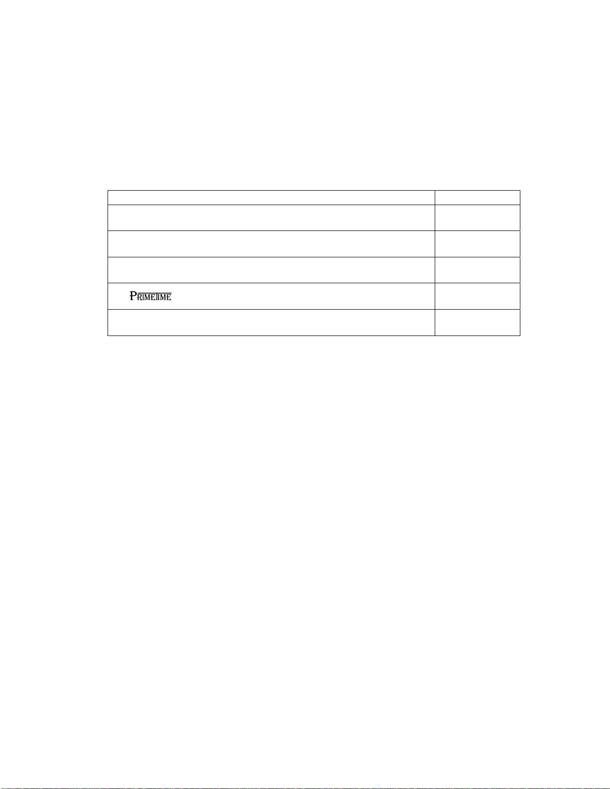
The table below indicates the items that you should find in your turbidimeter shipment.
Field Portable Turbidimeter with 4 AAA batteries installed 1
Calibration Set (0.02, 10.0 , 1000 NTU Standards) 1
Item Quantity
Instruction Card 1
Instrument Carrying Case 1
Empty Cuvettes & Kimwipes® 2
Remove the instrument from the packing carton. Carefully inspect all items to ensure
that no visible damage has occurred during shipment. If the items you received do not
match your order, please immediately contact your local distributor or the HF scientific,
inc. Customer Service department.
Warning: Extra care should be taken when unpacking, opening, and handling the
calibration standards and sample cuvettes in the Accessory Kit; surface scratches or
finger smudges on the cuvette surface may cause measurement errors. Handle these
items by the cap of the cuvette only.
Note: The instrument is shipped with the batteries installed.
Figure 1 is a depiction of the top of the instrument. The three main components of the
instrument are the sample well, the display, and the touch pad. The following sections
will describe the functionality of the display and the touch pad. The proper use of the
instrument and the sample well will be discussed in later sections.
Ref. 22666 (12/04)
Rev. 1.4
2
Page 7

Figure 1: Top view of the instrument.
1.2 The Display
All of the items that can appear on the display are shown in Figure 2. The display is used
for reporting the turbidity levels and to provide user guidance in the customer setting
routine. In addition, the display also has several other blocks that are used to
communicate error messages and provide user guidance.
Figure 2 – Display used in the instrument.
1.3 The Instrument and Touch Pad
The touch pad has five buttons: ON/OFF, CAL, ↵, t, and u. The ON/OFF button is
used to turn the instrument on and off. The CAL button, when pressed, initiates the
calibration mode of the instrument. The
instrument that it should take a reading. The
calibration points.
↵ button, when pressed, indicates to the
tand u buttons are used to change the
Ref. 22666 (12/04)
Rev. 1.4
3
Page 8

2.0 Safety
This manual contains basic instructions that you must follow during the operation, care
and maintenance of the instrument. The safety protection provided by this equipment
may be impaired if it is used in a manner not described in this manual. It is
recommended that all operators should read this manual prior to working with this
instrument.
In certain instances NOTES, or helpful hints, have been highlighted to give further
clarification to the instructions. Refer to the Table of Contents to easily find specific
topics and to learn about unfamiliar terms.
Ref. 22666 (12/04)
Rev. 1.4
4
Page 9

3.0 Normal Operation
This instrument allows you to measure the turbidity of a grab sample. The turbidity is
reported in Nephelometric Turbidity Units (NTU). Readings above 1100 NTU are
outside the range of this instrument.
During normal operation, the instrument will have the last valid turbidity reading
indicated on the display (see illustration below).
If the sample that you are measuring has a turbidity that is higher than that which the
instrument can measure, the instrument will indicate this as an over-range condition:
In certain instances, during normal operation, the instrument will briefly display a row of
dashes across the display
This indicates that either the instrument is performing an auto-ranging function, or the
sample has a substantial amount of bubbles. If the dashes remain for an extended period
of time please ensure that the sample does not have a large amount of bubbles present; if
there are not bubbles present, please contact the Technical Services Department for
further assistance and guidance (refer to section 5.3).
3.1 Routine Measurement
The instrument measures and reports the turbidity of a sample in nephelometric turbidity
units (NTU’s).
Note: Nephelometric turbidity units (NTU’s) are numerically equivalent to Formazin
turbidity units (FTU’s) (See Glossary).
Ref. 22666 (12/04)
Rev. 1.4
5
Page 10

Turn on the instrument by pressing the ON/OFF button continuously for 1 second. Allow
75-second warm-up period while preparing for the turbidity measurement as described in
the following steps:
1. Sample approximately 100 ml of your process, as you would normally do for
turbidity measurement.
2. Obtain a clean and dry sample cuvette.
3. Rinse the cuvette with approximately 10 ml of the sample water (2/3 of cuvette
volume), capping the cuvette with the black light shield (cuvette top) and inverting
several times. Discard the used sample and repeat the rinsing procedure two more
times.
4. Completely fill the rinsed cuvette (from step 3) with the remaining portion
(approximately 15 ml) of the grab sample and then cap the cuvette with the supplied
cap. Ensure that the outside of the cuvette is dry, clean and free from smudges
1
5. Place the cuvette into the instrument and press it down until it snaps fully into the
sample well. Index the cuvette by pressing and holding down the ↵ button while
rotating the cuvette to identify the lowest reading (the displayed turbidity is
continuously updated on the display). Once the cuvette is indexed, release the
↵
button to display the measured turbidity (see Glossary for more information on
indexing a cuvette).
6. Repeat steps 1 through 5 for all of your samples.
Warning: NEVER pour liquid directly into the sample well of the instrument always use a
cuvette. The instrument will only accurately measure the turbidity of a sample
when cuvettes sealed with the black cap are used. The black cap serves as both
seal and a light shield.
Note: The instrument will turn off after approximately 5 minutes if no buttons are pressed.
1
Any typical glass cleaner can be used along with a lint free cloth, or tissue (Kimwipes®), to clean the outside of
the cuvette.
Ref. 22666 (12/04)
Rev. 1.4
6
Page 11

4.0 Instrument Calibration
The instrument was calibrated and tested prior to leaving the factory. Therefore, it is
possible to use the instrument directly out of the box. However, re-calibration of the
instrument is recommended to help you become familiar with the operation of the
instrument and the calibration procedures. In addition, re-calibration is recommended at
least once every three months.
The instrument requires four (4) standards to be fully calibrated.
During calibration, the instrument performs several system self-diagnostics. As such,
several warning messages may be displayed. If the instrument detects an irregularity
(detectors or lamp) a warning message will be displayed upon exiting the calibration
mode. If this occurs please attempt to rectify the problem yourself, or contact the
authorized technical services department (see section 5.2). In any event, the instrument
will continue to read the turbidity with a decreased accuracy until the error is rectified.
4.1 Calibration Standards
We recommend that you use the following materials
2
during calibration to achieve the
accuracy stated in this manual:
1. CAL 1: 1000 NTU
2. CAL 2: 100 NTU
3. CAL 3: 10.0 NTU
4. CAL 4: 0.02 NTU
Calibration Standard available from HF scientific inc. 3
Calibration Standard available from HF scientific inc. 3
Calibration Standard available from HF scientific inc. 3
Calibration Standard available from HF scientific inc. 3
It is well known that diluted Formazin is unstable. If you choose to use Formazin to
calibrate the instrument, ensure that you are using a fresh stock suspension of Formazin
to achieve the accuracy quoted for the instrument. A Formazin Stock Solution Kit is
available.
limited shelf life of 1 year. If you use the
calibration standards are more stable than Formazin and have a
calibration standards to calibrate the
instrument, review the expiration date to ensure that the standards have not expired.
calibration standards are a US EPA approved alternative standard to Formazin.
4.2 Indexing the Calibration Standards
The United States Environmental Protection Agency (US EPA) recommends that
cuvettes used for instrument calibration or sample measurement be indexed. To comply
with this recommendation, each calibration standard is supplied with an indexing ring
and each instrument has a reference point for quick and repeatable indexing of the
calibration standard. To index a calibration standard perform the following steps:
1. While holding down the
↵ button, slowly rotate the calibration standard one
complete revolution (360°) pausing between increments to allow the display to
update.
2
User prepared formazin may be used as an alternative to sealed calibration standards for calibration of this
instrument.
3
See section 7.0 for Accessories & Replacement Parts List.
Ref. 22666 (12/04)
Rev. 1.4
7
Page 12

2. While rotating the standard, observe the turbidity reading and locate the cuvette
position with the lowest turbidity reading.
3. With the calibration standard positioned at the location having the lowest turbidity
reading, install the Indexing Ring over the black light shield on the standard so that
the pointer of the Ring aligns with the reference arrow on the instrument.
4.3 Calibration Procedures
1. Select the calibration function of the instrument by pressing the CAL button once.
The “CAL” block will be illuminated on the display with “1” indicating the standard
required for this step of the calibration. This is the first standard that should be used
in a full calibration.
2. Insert the 1000 NTU standard (CAL 1 in the figure above) into the sample well and
press down until the cuvette snaps fully into the instrument. Align the indexing ring
with the arrow on the instrument (see section 4.2 if you have not already indexed the
Standard).
3. Wait for the reading to stabilize. Once the reading has stabilized press the
to indicate to the instrument that it should calibrate on this point. You will see
something similar to the display shown below.
↵ button
4. When the instrument has completed calibration on this point, it prompts you to insert
the next calibration standard into the sample well (CAL 2).
5. Repeat steps 2-4 for each calibration standard. When you calibrate on CAL 4
(turbidity free water), the instrument will automatically exit out of calibration
returning back to the normal operating mode.
Notes :
1. During calibration, the screen actively displays the current turbidity value.
After the CAL value changes, it is common for the display to not report the exact
turbidity of the standard as it either is expecting a new standard or has not yet
calibrated the new standard.
2. If you wish to exit the calibration mode you may do so at the end of any step by
pressing the CAL button. The instrument will accept only the values calibrated
prior to exiting.
Ref. 22666 (12/04)
Rev. 1.4
8
Page 13

5.0 Troubleshooting
The instrument routinely performs self-diagnostics, and will automatically generate
messages to provide you with specific diagnostic information.
5.1 System Warning Messages
Automatic warning messages are generated to provide you with specific diagnostic
information about the instrument. These messages are for your use and do not indicate a
reduction in the performance of the instrument or a failure of any component in the
instrument.
Flashing Battery Symbol:
need to be replaced. Under this condition, you should replace the batteries as soon as
possible to ensure that the instrument will continue to function properly. If the batteries
get too low to accurately measure, the instrument will turn off. The instrument might not
turn back on until the batteries have been replaced. See section 6.2 for more information
5.2 System Error Messages
Normally, the cause of an error message is external to the instrument. If an error is
identified the instrument will flash the error block (ERR) along with the error number.
A flashing battery on the display indicates that the batteries
Ref. 22666 (12/04)
Rev. 1.4
9
Page 14

The following table lists the error messages and their associated meanings:
Error ASSOCIATED MEANING TYPICAL CAUSE
1 Lamp failure Lamp has too low an output for proper
turbidity measurement.
2 General Calibration failure:
There is not sufficient signal
between the 0.02 NTU and 10.0
NTU standards used for
calibration
3 General Calibration failure:
There is not sufficient signal
between the 10.0 NTU and 100.0
NTU standards used for
calibration
4 General Calibration failure:
There is not sufficient signal
between the 100.0 NTU and
1000.0 NTU standards used for
calibration
Err Multiple error conditions are met
Either the wrong standards were used in
calibration or there is an internal sensor
failure.
Either the wrong standards were used in
calibration or there is an internal sensor
failure.
Either the wrong standards were used in
calibration or there is an internal sensor
failure.
5.3 Technical and Customer Assistance
If you need assistance regarding this instrument please contact the HF scientific, inc.
Technical Service Department.
HF scientific, inc.
3170 Metro Parkway
Fort Myers, Florida 33916-7597
Phone: (239) 337-2116
Fax: (239) 332-7643
Email: info@hfscientific.com
Ref. 22666 (12/04)
Rev. 1.4
10
Page 15

6.0 Routine Maintenance
If you do not plan on leaving the instrument in the supplied carrying case, when not in
use, ensure that the instrument has been turned off and that a clean sample cuvette fitted
with a black cap has been placed in the sample well. This will ensure that a minimal
amount of dust and/or debris will be able to settle on the optics of the instrument.
6.1 Cuvette Cleaning and Care
Proper measurement of the turbidity of a sample requires the use of a cuvette that is free
of marks, smudges, scratches and any bacterial growth. Cleaning the cuvette is
accomplished by washing the interior and exterior of the cuvette in a detergent solution.
Once cleaned, the cuvette should be rinsed thoroughly 8 to 10 times with clean distilled
water to eliminate the possibility of detergent buildup and streaking. Cleaned and dried
cuvettes should be stored with the black caps on. The cuvettes can be stored in a cuvette
rack (see accessories and replacement parts list). During normal operation you may use
any typical glass cleaner along with a lint free cloth or tissue (Kimwipes®), to clean the
outside of the cuvettes.
Condensation may appear on the cuvette when your sample is very cold and the relative
humidity is high. When this happens, the turbidity that you read may be higher than the
actual turbidity due to the light scattered by the condensate on the cuvette. If you find
yourself in this circumstance you can alleviate the problem by either coating the cuvette
with an anti-fogging agent, or by running warm water over the cuvette for a short period
of time to warm the sample prior to measurement.
Ref. 22666 (12/04)
Rev. 1.4
11
Page 16

6.2 Battery Replacement
The instrument will periodically require new batteries to function properly. This will be
indicated with a flashing battery indicator on the display. To replace the batteries:
1. Turn the instrument off and place it upside down on a soft surface.
2. Remove the two screws (A) securing the battery cover (B). Lift cover off.
3. Remove the old batteries. Place four new AAA batteries (C) into the battery
compartment (ensuring the correct polarity).
4. Replace the battery cover and fasten the two screws carefully to ensure a watertight
seal.
5. Dispose of used batteries in accordance with all federal, state and local regulations.
Figure 3: Detailed view of the battery compartment
Ref. 22666 (12/04)
Rev. 1.4
12
Page 17

7.0 Accessories and Replacement Parts List
The items shown below are recommended accessories and replacement parts for the
instrument.
Accessory Catalog Number
Calibration Set for normal operation (includes 0.02
NTU, 10.0 NTU, 100.0 NTU and 1000 NTU Standards).
Turbidity Free Water, 4 Liters (1gal.) 70908
Formazin Stock Solution, 4000 NTU, 500 mL 70914
Operators Manual 22666
Formazin Stock Solution Kit 50040
Sample Cuvettes – 3 pack
Rechargeable Battery Kit
To order any accessory or replacement part, please contact the HF scientific, inc.
Customer Service Department. See section 5.3 for contact information.
29855
19856
19859
Ref. 22666 (12/04)
Rev. 1.4
13
Page 18

8.0 Warranty
The manufacturer warrants to the original purchaser of this instrument that it will be free
of defects in material and workmanship, in normal use and service, for a period of one
year from date of delivery to the original purchaser. The manufacturer’s obligation under
this warranty is limited to replacing, at its factory, the instrument or any part thereof.
Parts, which by their nature are normally required to be replaced periodically, consistent
with normal maintenance, specifically lamps including fluorescent backlight, reagent,
desiccant, sensors, electrodes and fuses are excluded. Also excluded are accessories and
supply type items.
Original purchaser is responsible for return of the instruments, or parts thereof, to the
manufacturer’s factory. This includes all freight charges incurred in shipping to and from
the manufacturer’s factory.
The manufacturer is not responsible for damage to the instrument, or parts thereof,
resulting from misuse, negligence or accident, or defects resulting from repairs,
alterations or installation made by any person or company not authorized by the
manufacturer.
The manufacturer assumes no liability for consequential damage of any kind, and the
original purchaser, by placement of any order for the instrument, or parts thereof, shall be
deemed liable for any and all damages incurred by the use or misuse of the instruments,
or parts thereof, by the purchaser, its employees, or others, following receipt thereof.
Carefully inspect this product for shipping damage, if damaged, immediately notify the
shipping company and arrange an on-site inspection. The manufacturer cannot be
responsible for damage in shipment and cannot assist with claims without an on-site
inspection of the damage.
This warranty is given expressly and in lieu of all other warranties, expressed or implied.
Purchaser agrees that there is no warranty on merchantability and that there are no other
warranties, expressed or implied. No agent is authorized to assume for the manufacturer
any liability except as set forth above.
8.1 Waterproof Seal
Opening the main instrument enclosure (excluding the battery compartment) may void
the warranty.
Ref. 22666 (12/04)
Rev. 1.4
14
Page 19

Glossary
Formazin Nephelometric Units (FNU): see Nephelometric Turbidity Units
Formazin Turbidity Units (FTU): see Nephelometric Turbidity Units
Indexing a Cuvette: The United States Environmental Protection Agency (US EPA)
recommends that cuvettes used for turbidimeter calibration or sample measurement be indexed.
To index a cuvette with a sample in it, slowly rotate the cuvette throughout one complete
revolution (360°). While rotating the sample cuvette, observe the display and locate the
position that the cuvette is in which provides the lowest turbidity reading. This position is the
indexed position of the cuvette. Refer to section 4.2 of this manual to learn how to index a
cuvette in this instrument.
Nephelometric Turbidity Units (NTU): Unit of measure used when relating the light scattered by
a liquid media to the light scattered by a known concentration of Formazin Polymer. This unit
of measure is recognized as a measure of the optical clarity of an aqueous sample. NTU is the
accepted unit of measurement for turbidity.
Turbidity: 1) A measure of the attenuation of a radiant flux as it passes through a liquid media.
2) Optical clarity of a liquid, 3) A phenomena caused by the presence of undissolved matter in a
liquid media.
Ref. 22666 (12/04)
Rev. 1.4
15
 Loading...