

Page 1
OWNER’S MANUAL
HF scientific– Micro 1000 Laboratory
Turbidimeter 0-10,000 NTU
HF scientific
3170 Metro Parkway
Ft. Myers, FL 33916
Phone: (239) 337-2116
Fax: (239) 332-7643
Toll free: 888-203-7248
Email: HF info@Watts.com
Website: www.hfscientific.com
Catalog No. 22615 (1/11)
Rev 3.2
Page 2

Page 3

DECLARATION OF CONFORMITY
Application of Council Directive: 73/23/EEC
Standard to which Conformity is Declared:
Product Safety Immunity & EMI
UL3101-1 EN61326-1: 2006
CSA-C22.2 No. 1010-1-92
EN61010-1: 1993 + A2: 1995
Manufacture’s Name: HF scientific, inc.
Manufacture’s Address: 3170 Metro Parkway, Fort Myers, Florida 33916-7597
Importer’s Name:
Importer’s Address:
Type of Equipment: Laboratory Turbidimeter
Model No.: Micro 1000 Catalog Numbers: 20014
Micro 1000 IR 20016
I, the undersigned, hereby declare that the equipment specified above conforms to the
above Directive and Standard.
Place: Fort Myers, Florida USA
(Signature)
Rowan T. Connelly, General Manager
Rev. 3.2 i
Page 4

Page 5

1. SPECIFICATIONS..........................................................................................................................1
2. Overview..........................................................................................................................................2
2.1. Unpacking and Inspection of the Instrument and Accessories................................................................................2
2.2. User Interface..............................................................................................................................................................3
3. Safety ...............................................................................................................................................4
4. Routine Operation............................................................................................................................5
4.1. Measurement Principle & Methodology...................................................................................................................5
4.2. Grab Sample Measurement (Routine Measurement).............................................................................................. 6
4.3. Pour Through Sample Measurement (Optional Accessory)....................................................................................7
4.4. Flow Through Sample Measurement (Optional Accessory)....................................................................................7
4.5. Dry Air Purge System.................................................................................................................................................8
4.6. Using the Security Access Feature (Good Manufacturing Practice [GMP])..........................................................8
5. Calibration Procedures.....................................................................................................................8
5.1. Calibration Standards.................................................................................................................................................9
5.2. Indexing the Calibration Standard(s)........................................................................................................................9
5.3. Calibrating the Instrument.......................................................................................................................................10
6. Instrument Configuration (SETUP) Mode.....................................................................................13
6.1. Setting the Scale.........................................................................................................................................................13
6.2. Setting the Ratio Mode..............................................................................................................................................13
6.3. Selecting Display Resolution.....................................................................................................................................14
6.4. Configuring the Security Code.................................................................................................................................14
6.5. Setting up the RS232 Port (Printing Function).......................................................................................................15
6.6. Setting the Calibration Interval...............................................................................................................................16
6.7. Setting the Date (Year, Month and Day).................................................................................................................17
6.8. Setting the Time (Hours and Minutes)....................................................................................................................18
6.9. Exiting the setup mode..............................................................................................................................................18
7. Troubleshooting .............................................................................................................................20
7.1. System Warning Message(s).....................................................................................................................................20
7.2. System Error Message(s)..........................................................................................................................................23
7.3. Factory Default Parameters.....................................................................................................................................23
8. Routine Maintenance .....................................................................................................................23
8.1. Cuvette Cleaning and Care......................................................................................................................................24
8.2. Lamp Replacement ...................................................................................................................................................24
9. Contacting the HF scientific, inc. Technical Service Department.................................................25
Rev. 3.2 ii
Page 6

10. Accessories and Replacement Parts List........................................................................................25
11. Glossary .........................................................................................................................................26
12. Warranty ........................................................................................................................................27
Rev. 3.2 iii
Page 7
1.
SPECIFICATIONS
MICRO 1000 MICRO 1000IR
Instrument Conformance
Light Source Tungsten Filament Lamp Infrared LED
Measurement
Options and Ranges
NTU
FNU
EBC
NEPHELO
FAU
Signal Averaging Yes Yes
Auto Ranging Yes Yes
Accuracy †
0 – 1000 NTU
1000 – 4000 NTU
4000 – 10,000 NTU
Repeatability ± 1% of reading or ± 0.01 NTU
Resolution 0.0001 NTU below 10 NTU 0.0001 NTU below 10 NTU
Response Time Less than 6 seconds Less than 6 seconds
Serial Input/Output RS-232 Directional RS-232 Directional
Certifications CE, ETL (UL & CSA ) CE, ETL (UL & CSA)
Power Supply 15 V DC Wall Mount 15 V DC Wall Mount
Display Backlit Multi-Line LCD Backlit Multi-Line LCD
Miscellaneous
Specifications
Operating Temperature
Range
Sample Flow Rate
Through The Flow Cell
Air Purge 0.1 SCFM at 10 PSIG 0.1 SCFM at 10 PSIG
Shipping Dimensions 12” x 14” x 12”
Shipping Weight 7 lb (3.18 kg) 7 lb (3.18 kg)
Warranty 1 - Year 1 - Year
§
The specifications found in EPA method 180.1 are essentially the same as the specifications set out in method
2130B of the Standard Methods for the Examination of Water and Wastewater 19th edition and the
specifications set out in ASTM Standard Method D1889-94. This turbidimeter meets, or exceeds, the
specifications set forth in these methods.
†
Instrumental accuracy measured under controlled laboratory conditions at 25°C (77°F)
Conforms to specifications set forth in
EPA method 180.1 (Nephelometric
Method)
Ratio on or Ratio off
0 – 10,000
-------0 - 2,450
0 – 67,000
--------
± 2% of reading + 0.01 NTU
± 5% of Reading
± 10% of Reading
whichever is greater
1 - Built in Diagnostics
2 - Security Access Code
0° C – 50° C (32 ° F - 122° F) 0° C – 50° C (32 ° F - 122° F)
0.5 – 1.5 gpm (2-6 L/min)
60 psi max pressure (414 kPa)
(35.6cm x 30.5cm x 30.5cm)
§
Conforms to specifications set forth in
ISO 7027: Water Quality –Determination
of Turbidity
Ratio on or Ratio off
0 – 10,000
0 – 10,000
0 – 2,450
-------0 – 10,000
± 2% of reading + 0.01 NTU
± 5% of Reading
± 10% of Reading
± 1% of reading or ± 0.01 NTU
whichever is greater
1- Built in Diagnostics
2- Security Access Code
0.5 – 1.5 gpm (2-6 L/min)
60 psi max pressure (414 kPa)
12” x 14” x 12”
(35.6cm x 30.5cm x 30.5cm)
Rev. 3.2 1
Page 8
2. Overview
The Micro 1000 process turbidimeter allows you to measure the turbidity of your process water.
The White Light Micro 1000 has been designed to meet the design criteria specified by the US EPA
on turbidity measurement. The Infra-Red Micro 1000 (Micro 1000 IR) was designed to meet the
design criteria specified in ISO 7027 and DIN 27027 for the measurement of the turbidity of a
sample.
2.1.Unpacking and Inspection of the Instrument and Accessories
The table below indicates the items that you should find in your turbidimeter shipment.
Remove the Calibration Kit (Cardboard box), the Package of 3 Cuvettes and the instrument from the
packing carton. Carefully inspect all items to ensure that no visible damage has occurred during
shipment. If the items you received do not match your order, please contact your local distributor or
the HF scientific, inc. Customer Service department immediately.
ITEM Quantity
Laboratory Turbidimeter 1
Calibration Kit for the MICRO 1000 1
3 Pack of Cuvettes 1
MICRO 1000 Instruction Manual 1
Power Supply 1
Note: Extra care should be taken when unpacking, opening, and handling the calibration standards
and sample cuvettes in the Accessory Kit; surface scratches or finger smudges on the cuvette
surface may cause measurement errors. Handle these items by the top area of the cuvette only.
Rev. 3.2 2
Page 9
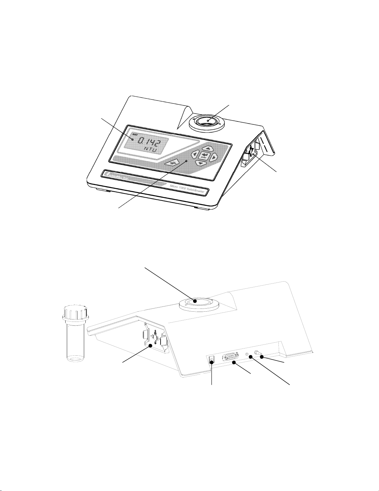
2.2.User Interface
The user interface of the instrument is designed with a 6 key touch pad and a single user display.
The six keys of the touch pad and their functionality are described below. Figures 1a and 1b are
depictions of the front and rear views of the instrument.
Optical Well
Display
Lamp Module
Touch Pad
Figure 1a - Front view of the Instrument
Optical Well
Lamp Module
15VDC
Air Purge In
RS-232
Air Purge Out
Figure 1b – Rear view of the Instrument
Rev. 3.2 3
Page 10
The ON/OFF key ( ) key is used to turn the instrument ON or OFF. The enter key ( ) is used
to accept information. The up and down arrow keys (SandT) are used to set and reset numerical
values and to change instrument modes. The left and right arrow keys (◄and►) are used to scroll
through lists. In addition, the rear panel of the instrument is designed to provide ready access to the
power plug connector, the RS-232 serial port and the dry air purge connector.
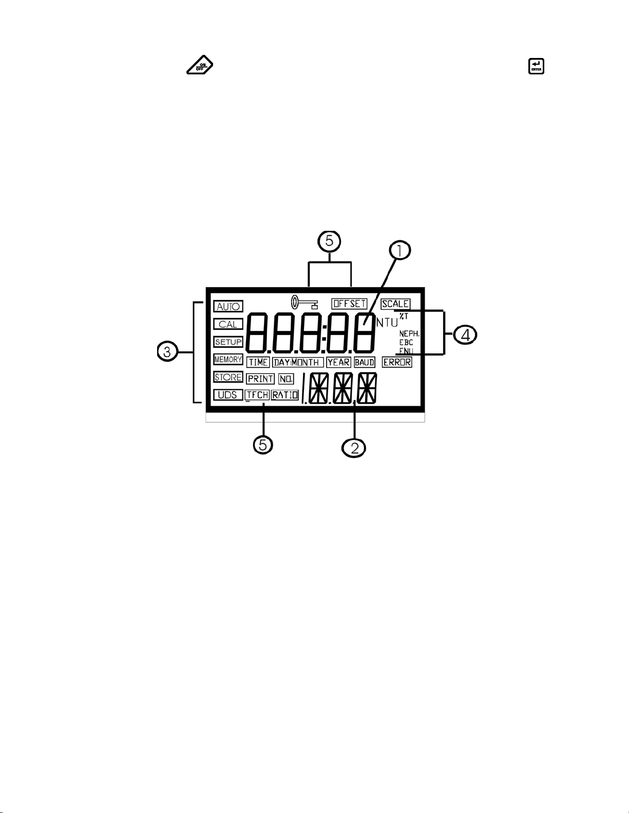
Figure 2 illustrates all the items that can appear on the display. The upper row of the display (1) is
used for reporting the turbidity levels and to provide user guidance in the customer setting routine.
The lower row of the display (2) is used to communicate error messages and user guidance. The
display has several status indicators (3) that distinguish the operation of the instrument. In addition
there are several indicators that display the different scales (4) that the instrument will report. Other
indicators (5) provide guidance when the setup and calibration routines are being used.
3. Safety
This manual contains basic instructions that you must follow during the commissioning, operation,
care and maintenance of the instrument. The safety protection provided by this equipment may be
impaired if it is commissioned and/or used in a manner not described in this manual. Consequently,
all responsible personnel must read this manual prior to working with this instrument.
Figure 2 – Display used in the instrument. All items that
are used on the display are shown in this figure
The instrument has a time-out feature that automatically returns the system operation to the normal
operation mode from any other mode after a five (5) minute period of inactivity.
Ensure that the instrument has been turned off prior to removing power from the instrument.
In certain instances WARNINGS, Notes, or helpful hints, have been highlighted to give further
clarification to the instructions. Refer to the Table of Contents to easily find specific topics and to
learn about unfamiliar terms.
Rev. 3.2 4
Page 11

4. Routine Operation
4.1. Measurement Principle & Methodology
This instrument is designed to measure the turbidity of a sample in nephelometric turbidity units
(NTU). In addition, the instrument is capable of measuring in several other standardized scales:
Scale Definition
Applicable Instrument (s)
White Light Infrared
Ratio - NTU Turbidity measured via a combination of
transmitted and 90° scattered light using
the 90° scattered light as the primary
detector signal. This is used to eliminate
effects of colored samples.
FNU Formazin Nephelometric Units (1 FNU =
1 NTU)
FAU Formazin Attenuation Units (turbidity
measured via transmitted light according
to ISO 7027 and DIN 27027)
EBC Turbidity scale of the European Brewery
Commission
Nephelos A turbidity scale used in microbiological
research to report progress of bacterial
growth (e.g. immunological assays). 6.7
Nephelos = 1 NTU. Nephelo is the Greek
word for cloud.
Yes Yes
No Yes
No Yes
Yes Yes
Yes No
The system measures these scales using five (5) separate detectors. Two detectors are located 90°
from the path of the light (nephelometric detectors) to ensure measurement redundancy and to
minimize variations in cuvettes. One detector is a reference detector that monitors the light output
by the light source (both white light and infrared). The reference detector is used to generate a more
accurate measure of turbidity should there be any fluctuation in lamp intensity (via voltage spikes or
lamp ageing). Finally, two detectors are used to measure transmission of light for the extended
turbidity range, for ratio measurement, and for determination of FAU’s (see below for definition).
In the course of normal operation, the embedded software measures the intensity of light at each
detector. During this operation, several advanced fuzzy logic techniques are used to determine if air
bubbles or large particles are passing through the path of light at the detector. If an anomaly is
detected, the algorithm identifies it and repeats the measurement prior to reporting the turbidity
levels. By monitoring all detectors, the instrument is able to perform system self-diagnostics; it is
able to ensure that all data collected from the detectors is consistent. Then, the calculations for
turbidity are made according to the methods described in the specifications section of the instrument
(section 1).
Rev. 3.2 5
Page 12
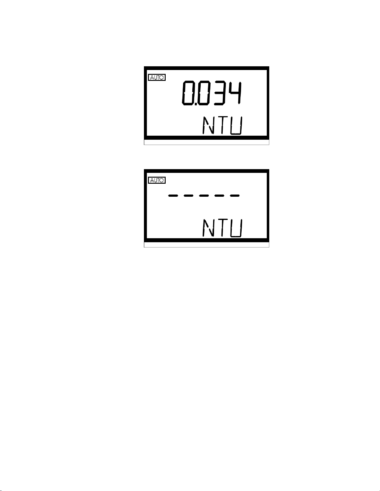
During normal operation, the AUTO block will be highlighted with the current scale displayed on
the lower row of the display and the measured reading on the upper row of the display:
In certain instances, during normal operation, the instrument will display a row of dashes across the
upper row of the display.
This indicates that either the instrument is performing an auto-ranging function, or the sample has
not yet stabilized (e.g. air coming out of solution in the form of bubbles). The dashes should remain
for a brief period of time (< 45 seconds). If the dashes remain for an extended period of time please
contact the HF scientific, inc. Technical Services Department for further assistance and guidance.
The following sections describe how to use the instrument under normal operating conditions.
These sections include details on how to take normal, routine turbidity measurements using the
instrument.
WARNING: NEVER pour liquid directly into the sample well of the instrument: always use a cuvette.
The instrument will accurately measure the turbidity of a sample using only cuvettes with the
black light shield on the cuvette (provided by HF scientific, inc.), the optional pour through
assembly, or the optional flow through assembly.
4.2. Grab Sample Measurement (Routine Measurement)
The following steps describe how to measure the turbidity of a grab sample using this instrument:
1. Turn on the instrument. The instrument will be in the normal operating mode. Allow instrument
to warm up for at least 30 minutes.
2. Sample approximately 100 ml of the process stream as you would normally do for turbidity
measurement.
3. Obtain a clean and dry sample cuvette.
4. Rinse the cuvette with approximately 20 ml of the sample water (2/3 of cuvette volume), capping
the cuvette with the black light shield (cuvette top) and inverting several times. Discard the 20
ml of used sample and repeat the rinsing procedure two more times.
Rev. 3.2 6
Page 13

5. Completely fill the rinsed cuvette (from step 4) with the remaining portion (approximately 30
ml) of the grab sample and then cap the cuvette with the black light shield. Ensure that the
outside of the cuvette is dry, clean and free from smudges.
6. Place the cuvette in the instrument and index the cuvette to the lowest reading (the displayed
turbidity is updated once a second). Once the cuvette is indexed, the reading displayed on the
instrument's display should be recorded as the sample turbidity (see Glossary for more
information on indexing a cuvette).
7. If you have turned off the printer output in the customer setup section, pressing the
time will output data to the RS232 port.
Repeat steps 2 through 7 for all of your samples.
4.3. Pour Through Sample Measurement (Optional Accessory)
Install the pour through assembly and index it according to the instruction sheet that accompanies
the assembly. The following steps describe how to measure the turbidity of a sample using the
instrument fitted with the optional pour through assembly:
1. Turn on the instrument. The instrument will be in the normal automatic mode. Allow
instrument to warm up for at least 30 minutes.
2. Sample approximately 500 ml of the process as you would normally do for turbidity
measurement.
3. Pour the complete 500 ml sample into the pour through assembly. Record the turbidity of the
sample displayed after the entire 500 ml sample has been poured into the assembly, the flow to
drain has ceased, and after the reading has stabilized.
4. If you have turned off the printer output in the customer setup section, pressing the key at this
time will output data to the RS232 port.
5. Repeat steps 2 through 4 for all of your samples.
key at this
The sample cuvette used in the pour through assembly is identical to the standard sample cuvettes
supplied with the instrument. Clean the cuvette on a periodic basis according to your experience
with the type and turbidity of the sample found in your facility.
4.4. Flow Through Sample Measurement (Optional Accessory)
Install the flow through assembly according to the instruction sheet that accompanies the assembly.
The following steps describe how to continuously measure the turbidity of a sample stream using the
instrument fitted with the optional flow through assembly:
1. Turn on the instrument. The instrument will be in the normal automatic mode. Allow
instrument to warm up for 30 minutes.
2. Initiate flow of the sample to the instrument and allow 2 minutes for the flow to stabilize prior to
recording the measured turbidity.
3. Begin to record the turbidity readings at the desired intervals.
4. If you have selected timed printer output in the customer setup section you should be able to
monitor the process in real time using PC data acquisition software.
The sample cuvette used in the flow through assembly is identical to the standard cuvettes supplied
with the instrument. Clean the cuvette on a regular basis according to your experience with the type
of turbidity sample found in your facility.
Rev. 3.2 7
Page 14
4.5. Dry Air Purge System
Cold samples, or the continuous flow of cool water through the flow-through cuvette may cause
condensation on the walls of the cuvette. This condensation can cause faulty and erratic readings
with the instrument. To eliminate this effect, a built in dry air purge system has been designed to
optimally circulate air through the optical compartment and prevent this condensation. This is a
particularly important feature when using either the pour through or the flow through option.
To use, connect the regulated dry air source to the air purge fitting on the rear panel of the
instrument. The fitting is designed for use with 1/8” I.D. flexible tubing. Allow air to flow as long
as needed to control condensation; dry nitrogen or instrument grade air up to 15 PSIG (103.5 kPa)
should be used at flow rates between 2 – 7 SCFH. Once installed allow the system approximately 15
minutes to evacuate the chamber before proceeding with your measurements.
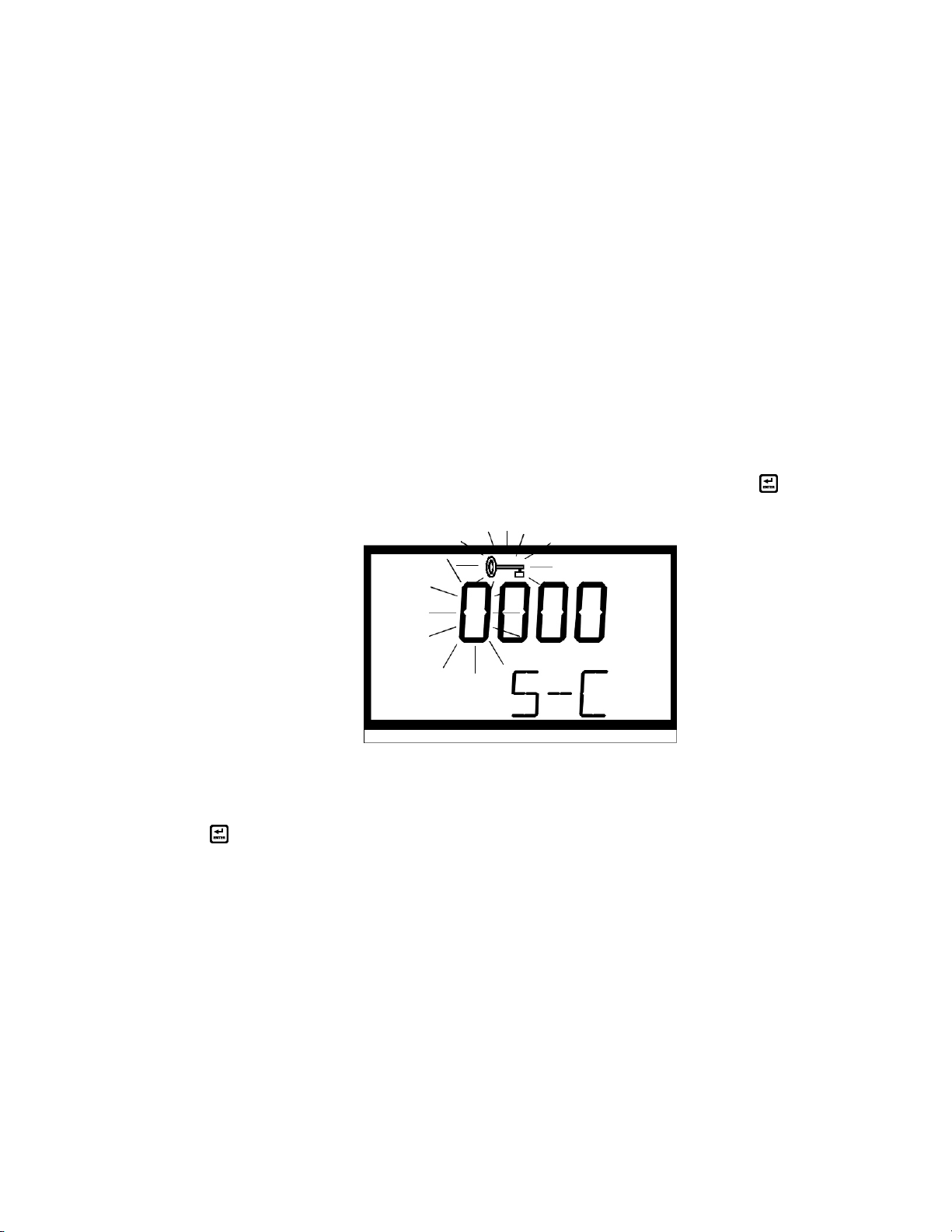
4.6. Using the Security Access Feature (Good Manufacturing Practice [GMP])
The instrument is equipped with a security feature that can be turned on, or off, when configuring
the instrument. Two access codes are used in the instrument and configurable by the user (see
section 8.3). The access code is required as an input whenever the user wishes to gain access to
either the calibration routine or the configuration (setup) routine when the feature is enabled. Use
either the S or keysT to select the mode that you wish to enter and then press the
security code option is turned on you will see the following display:
key. If the
This security code has four numbers that are selectable one at a time. The number that is flashing is
the first number for you to select. Use either the S or T keys to select this number in the code then
press the key to move to the next number. Follow this process through the four numbers in the
access code. If you have selected a valid access code, the instrument will be directed to either the
calibration or the configuration (user setup) mode depending on your original intention. If the wrong
access code is selected, the instrument will return to the normal automatic mode.
5. Calibration Procedures
The instrument was calibrated and tested prior to leaving the factory using calibration standards that
are traceable to the primary turbidity calibration standard, Formazin. Therefore, it is possible to use
the instrument directly out of the box. However, re-calibration of the instrument is recommended to
help you become familiar with the operation of the instrument and the calibration procedures.
Rev. 3.2 8
Page 15

Under normal conditions, re-calibration is recommended at least once every three months
may select a predetermined calibration interval for automatic prompting for calibration: if you
exceed the selected calibration interval, the "Cal" block will flash until the instrument is re-
calibrated.
During calibration, the instrument performs several system self-diagnostics. As such, several
warning messages may be displayed. If the instrument detects an irregularity with the instrument
(detectors or lamp) a warning message will be displayed on the lower row of the display on exit from
the calibration mode. If this occurs please attempt to rectify the warning message yourself, or
contact the HF scientific technical services department. In any event, the instrument will continue to
monitor the turbidity of the process water with a decreased accuracy until the error is
rectified.
In addition, if the instrument remains in the calibration mode for longer than 5 minutes with no
activity, it will time out and return to the automatic measuring mode.
Note: The instrument must be re-calibrated after lamp replacement.
5.1. Calibration Standards
HF scientific, inc. recommends that you use the following materials during calibration to achieve the
accuracy stated in this manual:
1. 0.02 NTU ProCal Calibration Standard available from HF scientific inc.
2. 10.0 NTU ProCal Calibration Standard available from HF scientific, inc.
1
. You
3. 100 NTU ProCal Calibration Standard available from HF scientific, inc.
4. 1750 NTU ProCal Calibration Standard available from HF scientific, inc.
5. 10000 NTU ProCal Calibration Standard available from HF scientific, inc.
It is well known that diluted Formazin is unstable. If you choose to use Formazin to calibrate the
instrument, ensure that you are using a fresh stock suspension of Formazin to achieve the accuracy
quoted for the instrument. A Formazin Stock Solution Kit is available from HF scientific (Catalog
No. 50040). The HF scientific ProCal, primary calibration sets (Catalog No.19927 or 19928) are
more stable than Formazin and have a minimum shelf life of 12 months. If you use the stable HF
calibration standards to calibrate the instrument, review the expiration date to ensure that the
standards have not expired.
Note: The 1750 NTU & 10000 NTU calibration standards must be inverted (well mixed) prior to use
to ensure the homogeneity and repeatability of the suspension for measurement. Do not shake.
5.2. Indexing the Calibration Standard(s)
The United States Environmental Protection Agency (US EPA) recommends that cuvettes used for
instrument calibration or sample measurement be indexed. To comply with this recommendation,
each HF scientific, inc. calibration standard is supplied with an indexing ring for quick and
repeatable indexing of the calibration standards. To index a calibration standard perform the
following two steps:
1
The EPA recommends that on-line turbidimeters be calibrated with the primary standard at least once every three months if they
are to be used for EPA reporting.
Rev. 3.2 9
Page 16

1. Slowly rotate the calibration standard one complete revolution (360°). While rotating the
standard, observe the measured turbidity and locate the position of the cuvette having the lowest
turbidity reading.
2. With the calibration standard positioned at the location having the lowest turbidity reading,
install the Indexing Ring over the black light shield on the standard so that the pointer of the
Ring faces forward, toward the operator.
When using the standards in the future, always insert the standard so that the pointer of the index
ring faces forward. Slowly rotate the standard back and forth about 5° to find the lowest point. The
standard is now indexed and ready to use.
5.3. Calibrating the Instrument
Even though it is possible to calibrate the instrument using any sequence of the prescribed
calibration standards, to achieve the stated accuracy you must use the procedure below to calibrate
the instrument.
1. Select the calibration function of the instrument by pressing either the up or down arrow key
until the “Cal” block is lit. Press the
displayed in the lower row of the display should read 0.02 NTU. This is the first standard that
must be used in calibration.
key. The cal block will now be lit and the turbidity
2. Insert the 0.02 NTU calibration standard into the sample well and index the standard if you have
not already done so (see section 5.2). At this point press the key to initiate calibration on the
0.02 NTU standard. The instrument will calibrate on the 0.02 NTU level (the “Cal” block and
the “Store” block will flash on and off for a period of time and you will see a countdown from
90).
Note: The 0.02 NTU standard must be evaluated in calibration at both the start and end of calibration
to ensure accurate measurements in the ratio mode and when recording FAU measurements.
Rev. 3.2 10
Page 17

3. When the instrument has completed the calibration, the “Cal” and the “Store” blocks will quit
flashing and the lower row of the display should now indicate that the 1750 NTU standard is the
next standard to be used for calibration (1.75 K).
Press the key to indicate to the instrument that you plan to calibrate on this point.
4. Invert the 1750 NTU calibration standard several times to mix prior to use.Insert the 1750 NTU
calibration standard into the sample well and calibrate as before. When the instrument has
completed the calibration, the “Cal” and the “Store” blocks will quit flashing and the lower row
of the display should now indicate that the 10000 NTU standard is the next standard to be used
for calibration (10.0 K).
5. If you plan to measure turbidity levels above 1750 NTU you must calibrate using a 10000 NTU
calibration standard (not included in the calibration kit). If you do not plan to measure turbidity
levels above 10000 NTU then use the arrow buttons until the lower row of the display shows
100.0 and then proceed to step #6. Otherwise, Invert the 10000 standard several times to mix
then insert the standard into the sample well and calibrate as before. When the instrument has
completed the calibration, these blocks will quit flashing and the lower row of the display should
now indicate that the 100.0 NTU standard is the next standard to be used for calibration.
Rev. 3.2 11
Page 18

6. Insert the 100.0 NTU calibration standard into the sample well and calibrate as before. When the
instrument has completed the calibration, , the “Cal” and the “Store” blocks will quit flashing
and the lower row of the display should now indicate that the 10.0 NTU standard is the next
standard to be used for calibration.
7. Insert the 10.0 NTU calibration standard into the sample well and calibrate as before. When the
instrument has completed the calibration, , the “Cal” and the “Store” blocks will quit flashing
and the lower row of the display should now indicate that the 0.02 NTU standard is the next
standard to be used for calibration.
8. Insert the 0.02 NTU calibration standard into the sample well and calibrate as before. When the
instrument has completed the calibration, the “Cal” and the “Store” blocks will quit flashing and
the lower row of the display should now display the word “END” indicating that the instrument
has completed the calibration phase and you can can now exit into the normal mode for
measurement.
9. If you wish to exit into the return to the normal operating mode press the
you wish to reperform the calibration, use either the ◄or ► keys to maneuver back to the
standard that you wish to work with.
key at this time. If
Rev. 3.2 12
Page 19

Notes: 1. You must use the 0.02 NTU standard at the beginning and end of the calibration cycle
to ensure accurate calibration of the instrument.
2. During calibration, the instrument performs some system self-diagnostics. Several
warning or error messages may be displayed. If there is an error in calibration, the
associated warning or error message(s) will be displayed in the lower row of the LCD
screen. Refer to the section on troubleshooting to determine the cause of the warning or
error.
3. At any point in time during calibration, you can cycle through the required calibration
points (0.02 NTU, 10 NTU, 100,0 NTU, 1750.0 NTU, and 10000.0 NTU) by pressing
either the ◄ or ► key to individually calibrate with a particular calibration standard.
If you wish to exit the calibration mode you may do so at any time by simply pressing
the ◄ or ► key until the word “END” is shown on the lower row of the display and
then pressing the
all of the steps for calibration may cause the accuracy of the instrument to be
diminished.
key. However, exiting the calibration process without completing
6. Instrument Configuration (SETUP) Mode
The instrument allows you to configure it according to your needs at any time during normal
operation (except when you are performing an instrument calibration). This section describes how
you can customize your instrument.
You can enter the SETUP mode of the instrument by pressing either the S or T key until the
“SETUP” block is highlighted. At this point, press the key and you will either enter the SETUP
mode or be prompted to enter the security code.
Note: To skip the selection of any parameter simply press either the ◄ or ► key to continue on to the
next (or previous) section.
6.1. Setting the Scale
After pressing the key, the Scale block will be lit and the current scale (measured units) will be
displayed on the lower row of the display.
Press either the S or T keys to change the units that will be displayed during normal automatic
measurement mode. When you have selected the desired units press the key.
6.2. Setting the Ratio Mode
After pressing the
the state of the Ratio Mode in the instrument.
key, the Ratio block will be lit and the lower row of the display will indicate
Rev. 3.2 13
Page 20

This feature is designed to decrease the sensitivity of the instrument to dissolved materials that may
adversely affect a turbidity reading (e.g. dissolve material creating color). Press either the S or T
keys to change the operational state of this option in the instrument. When you have selected the
desired state press the
6.3. Selecting Display Resolution
The instrument is equipped with the ability to display several levels of resolution (number of digits
to the right of the decimal place). The instrument is capable of displaying turbidity with a resolution
of four digits to the right of the decimal place (0.0001) for turbidity readings below 10 NTU. If you
feel that the last digit, or two, is not stable, or useable, then you may suppress these digits by
selecting the proper display resolution.
After setting up the ratio mode functionality, the upper row of the display will show the current
resolution; the lower row of the display will show the letters “RES.”
key
You have the ability to select the resolution shown on the display by pressing either the S or T
keys to change the resolution to be used. When you have selected the desired resolution press the
key.
6.4. Configuring the Security Code
The instrument is equipped with a security access option. If this option is turned on, the user must
input the access code to gain access to calibration or instrument configuration. The security key will
be highlighted on the display and the word “S-C” will be shown on the lower row of the display.
Rev. 3.2 14
Page 21

The upper row of the display will indicate the operational status of the security access option (on or
off). You can change the operational status of this option using either the S or T keys. Once you
have set the desired status, press the
If you selected to turn on the security access code, you will need to input an access code to be used
for entering calibration and for entering the configuration mode. The security key will be
highlighted on the display and the word “S-C” will be shown on the lower row of the display while
the current access code for entering calibration is shown on the upper row of the display (C followed
by 4 numbers).
If you wish to change the code you may change each of the four numbers one at a time. Use either
the S or T keys to select the first number in the code then press the key to move to the next
number. Follow this process through the four numbers in the access code. When you are satisfied
with your selection, press the key to accept the number. The access code will change from the
calibration access code to the configuration (user setup) access code (S followed by 4 numbers).
key to accept it.
Select the access code for the configuration/setup mode as you did with the calibration mode.
6.5. Setting up the RS232 Port (Printing Function)
After pressing the key, the Print block will be lit and the lower row of the display will indicate the
state of the RS232 port.
Rev. 3.2 15
Page 22

This feature allows you to select the function of the serial port on the instrument. There are two
options to choose from: Off and Timed Output. Select the RS232 option by pressing either the Sor
T keys. When you have selected the proper function, press the key.
Off: When the RS232 port is turned “Off” you may obtain a printout of the displayed
turbidity level each time you press the key in normal mode.
Timed Output: Several automatic printing times are available: 5 sec, 30 sec, 1 min, 5 min,
10 min, 15 min, 30 min and 60 min. If you selected this option, the instrument will print
out the average turbidity level, time, and date for the interval that you select. The timing
for the interval starts at midnight.
If you selected to turn off the RS232 port, pressing the key will send you to the portion of the
code that sets up the date. If, on the other hand, you selected to either turn on the printing function,
pressing the key will cause the Baud block to be highlighted and you can select the correct baud
rate for operation of your printer.
Select the desired baud rate (1200, 2400, 4800, or 9600) by pressing either the S or T keys to
change the displayed baud rate. The other RS 232 parameters are fixed at 1 stop bit, 8 data bits and
no parity. When you have selected the proper baud rate press the key.
Note: If the security code is enabled and the calibration interval has not been exceeded the letters
“QC” will follow each printout indicating the instrument is functioning properly in a secure
fashion. If the security code is turned off, or if the calibration interval has been exceeded the
“QC” mark will not appear on the printout.
6.6. Setting the Calibration Interval
After pressing the key, the lower row of the display will have the letters “Int” printed in it. The
number in the upper row of the display corresponds to the number of days that you wish to have
between scheduled calibrations (default is 30 days).
Rev. 3.2 16
Page 23

Select the desired number of days between scheduled calibrations by pressing either the S or T
keys to change the displayed day. In normal automatic mode, if you exceed this number of days
between calibrations, the Cal block will flash until you re-calibrate the instrument. When you have
selected the desired calibration interval press the key.
6.7. Setting the Date (Year, Month and Day)
With the Year block highlighted and the year displayed, change the displayed year using either the
S or T keys. When you have selected the proper year press the key to accept the year.
After pressing the key, the Day:Month block will be displayed and you will see two numbers on
the upper row of the display. The number flashing corresponds to the month.
Select the correct month by pressing either the S or T keys to change the displayed month. When
you have selected the proper month, press the key. After pressing the key, the
Day:Month block will remain displayed and the second number on the upper row of the display will
be flashing: this number corresponds to the day of the month.
Rev. 3.2 17
Page 24

Select the correct day by pressing either the S or T keys to change the displayed day. When you
have selected the proper day, press the
6.8.Setting the Time (Hours and Minutes)
After pressing the
the upper row of the display in 24-hour format. The number flashing corresponds to the hour.
Select the correct hour by pressing either the S or T keys to change the displayed hour. When you
have selected the proper hour, press the key. After pressing the key, the Time block will
remain displayed and the second number on the upper row of the display will be flashing: this
number corresponds to minutes.
key, the Time block will be displayed and you will see the time displayed on
key.
Select the correct minutes level by pressing either the S or T keys to change the displayed minutes.
When you have selected the proper minutes level, press the key.
Note: The number of seconds in the minute will be reset to zero when the
selecting the proper minutes level.
6.9. Exiting the setup mode
After you have pressed the
lower row of the display.
Rev. 3.2 18
key for selecting the time, the word “END” will be shown on the
key is pressed after
Page 25

You may also reach this point by pressing either the ◄ or ► key until the word “END” appears on
the lower row of the display. At this point, simply press the
key to return to the normal mode.
Rev. 3.2 19
Page 26

7. Troubleshooting
7.1. System Warning Message(s)
The instrument generates warning messages to provide you with specific diagnostic information about
the instrument. These messages are for your use and do not reduce the performance of the instrument.
The following sections outline warning messages that could be observed during normal operation.
7.1.1. Flashing “Cal” block A flashing "Cal" block observed during normal automatic mode indicates that you should re-
calibrate your instrument.
The factory default is 30 days. HF scientific inc. recommends calibration every 30 days. The
flashing "Cal” block is only a warning and does not mean that the instrument will stop performing
accurately. The "Cal" block will flash until you have re-calibrated the instrument.
7.1.2. Sample Over-Range (“O-r”)
The instrument is capable of reading the turbidity of samples up to 10,000 NTU (or equivalent in the
other scales). If the turbidity of the sample is determined to be higher than 10,000 NTU, the
instrument will report “O-r” in the upper row of the display.
Rev. 3.2 20
Page 27

7.1.3. Other warning messages (W-XX)
The following table outlines the general warning messages that could arise (normally after calibration is
performed).
Rev. 3.2 21
Page 28

WARNING ASSOCIATED MEANING TYPICAL CAUSE
W-01 Lamp Failure The lamp is no longer working, or the light output
of the lamp is too low for normal operation.
W-02 Transmission detector #1 error Transmission detector #1 failed to report the
proper signal levels during calibration (the
detector circuitry has failed or calibration was
performed with the wrong standards).
W-03 Transmission detector #2 error Transmission detector #2 failed to report the
proper signal levels during calibration (the
detector circuitry has failed or calibration was
performed with the wrong standards).
W-04 Nephelometric detector (90°) error The nephelometric detector failed to report the
proper signal levels during calibration (the
detector circuitry has failed or calibration was
performed with the wrong standards).
W-05 Reference detector The reference detector failed to report the proper
signal levels during calibration (the detector
circuitry has failed or calibration was performed
with the wrong standards).
W-06 Calibration failure on range 0-10
NTU.
W-07 Calibration failure on range 10-100
NTU.
W-08 Calibration failure on range 100-1750
NTU.
WNG Multiple warnings have occurred Calibration was performed with the wrong
The signal difference obtained between the 0.02
NTU and 10.0 NTU calibration standards was too
small to ensure the resolution in the specifications.
Verify that you used the correct standards during
calibration.
The signal difference obtained between the 10.0
NTU and 100.0 NTU calibration standards was
too small to ensure the resolution in the
specifications. Verify that you used the correct
standards during calibration.
The signal difference obtained between the 100.0
NTU and 1750.0 NTU calibration standards was
too small to ensure the resolution in the
specifications. Verify that you used the correct
standards during calibration.
standards or the lamp failed during calibration.
Rev. 3.2 22
Page 29

7.2. System Error Message(s)
The instrument generates error messages when problems are detected during normal operation.
When these messages are observed and if you do not understand the instructions shown below,
contact the HF scientific Technical Services department to determine a resolution to the problem.
The instrument indicates an error message when an "E-XX" is displayed on the lower row of the
display.
The instrument has several error codes, each assessing a different component or system of
components in the instrument. The following table lists the error messages and their associated
meanings.
ERROR ASSOCIATED MEANING TYPICAL CAUSE
E-01 The A/D has failed to report
correctly
SFE
If an error is noted, please contact the HF scientific Technical Services Department immediately to
rectify the error.
7.3. Factory Default Parameters
The instrument retains all original factory settings in non-volatile memory. At any time, you can
cause the instrument to change back to these default settings. This is particularly useful if you feel
that your calibration standards may have been compromised or if someone has erred in their use of
the instrument. In these situations you may use the factory default parameters while waiting for new
standards (or instructions) to arrive from HF scientific, inc.
General Electronics Failure One or many electrical components have
One or several components in the A/D circuit
has failed … call technical service
immediately
failed in the instrument.
To invoke this option, turn the instrument on and then press the S key while holding down the ◄
key. The instrument will perform several operations (taking approximately 2 minutes) and then turn
off indicating that the memory and all settings have been reset to the factory default parameters.
After this point you may start to use the instrument again as you normally would.
8. Routine Maintenance
The instrument has been designed for ease of use and simple operation. When not in use, ensure that
the instrument has been turned off and that a clean sample cuvette fitted with a black light shield cap
has been placed in the sample well. This will ensure that a minimal amount of dust and/or debris
will be able to settle on the optics of the instrument.
Rev. 3.2 23
Page 30

8.1.Cuvette Cleaning and Care
Proper measurement of the turbidity of a sample requires the use of a cuvette that is free of marks,
smudges, scratches and any bacterial growth. Any typical glass cleaner can be used along with a lint
free cloth, or tissue, to clean the outside of the cuvette. The inside of the cuvette can also be cleaned
with any typical glass cleaner. Once cleaned, the cuvette should be rinsed thoroughly 8 to 10 times
with clean distilled water to eliminate the possibility of detergent build-up and streaking. Cleaned
and dried cuvettes should be stored with the black light shield cap on the cuvette and can be stored in
a cuvette rack (see accessories and replacement parts list). During normal operation you may use
any typical glass cleaner along with a lint free cloth, or tissue, to clean the outside of the cuvettes.
8.2.Lamp Replacement
Periodically the lamp module will require replacement. Figure 1 illustrates the location of the lamp
module. An error message will be illuminated when it is time to replace the lamp (see
Troubleshooting). We recommended that you keep one spare lamp module for each instrument on
hand at all times to ensure continuous use of the instrument.
Before replacing the lamp module ensure that the instrument is turned off. Once you have turned off
the instrument, proceed with the following instructions:
1. Remove the lamp module from the instrument by squeezing the two side tabs on the module
inward while pulling the module out of the instrument. Pull the module away from the
instrument until the in-line power connector is exposed (about 6-8 inches).
2. Unfasten the connector by holding on to the white in-line connector and pulling the in-line
connector apart. When pulling the in-line connector apart, DO NOT hold on to the wires.
3. The new lamp module can now be connected to the instrument using the in-line power
connector.
4. Feed the wire back into the instrument being careful that the wire does not get in the way of the
lamp or the lamp holder (on instrument). Make sure that the light bulb icon on the back of the
lamp module is upright. Press the module into the instrument until you hear it click firmly into
place.
8.3.Battery Replacement
The Micro 1000 contains a non-rechargeable 10-year life lithium battery for backup of the real-time
clock. This battery is not field replaceable. Failure of this battery will not impede the use of the
instrument, however some time-related activities such as timed printouts will not operate. Contact
the HF scientific inc. Service Dept. for replacement of this item.
Note: The side tabs may need to be pressed outward until they click to secure the new lamp module.
5. If the two side tabs on the lamp module do not click the lamp module securely in place, check
that the power wire is not obstructing the lamp module.
6. Turn on the instrument and follow the instructions in section 4.1 to re-calibrate the instrument
with the new lamp module. The instrument must be re-calibrated after lamp module
replacement.
7. Resume normal operation after recalibrating the instrument.
Rev. 3.2 24
Page 31

9. Contacting the HF scientific, inc. Technical Service Department
For technical assistance or to order replacement parts please contact the HF scientific Technical
Services Department or HF scientific Customer Service Department.
HF scientific
3170 Metro Parkway
Fort Myers, Florida 33916-7597
Phone: (239) 337-2116 Toll free: 888-203-7248
Fax: (239) 332-7643
Email: HFinfo@Watts.com
10. Accessories and Replacement Parts List
Accessory or Replacement Part Catalog Number
Micro 1000 ProCal Calibration Set (includes 0.02 NTU, 10.0NTU, 100
NTU & 1750 NTU Calibration Standards)
High Range ProCal Calibration Standard for White Light, 10000 NTU
Micro 1000 IR ProCal Calibration Set (includes 0.02 NTU, 10.0NTU,
100 NTU & 1750 NTU Calibration Standards)
High Range ProCal Calibration Standard for IR light, 10000 NTU
Formazin Stock Solution Kit 50040
Formazin, 4000 NTU Stock Solution, 500 ml 70914
Lamp Module – Tungsten Filament 19972
Lamp Module – IR 24547S
Turbidity Free Water 70908
Pour Through Assembly 19975
39927
39938
39928
39939
Flow Through Assembly 19989
Cuvette Stand (holds 11 cuvettes) 19981
Sample Cuvettes – 3 pack 50051
Sample Cuvettes – 10 pack 50052
Micro 1000 Manual 22588
RS232 Cable for Serial Printer 19798
Rev. 3.2 25
Page 32

11.
Glossary
Formazin Turbidity Units (FTU): see Nephelometric Turbidity Units
Indexing a Cuvette: The United States Environmental Protection Agency (US EPA) recommends
that cuvettes used for turbidimeter calibration or sample measurement be indexed. To index a
cuvette with a sample in it, slowly rotate the cuvette throughout one complete revolution (360°).
While rotating the sample cuvette, observe the display and locate the position that the cuvette is
in which provides the lowest turbidity reading. This position is the indexed position of the
cuvette.
Nephelometric Turbidity Units (NTU): Unit of measure used when comparing the light scattered by
a liquid media to the light scattered by a known concentration of Formazin Polymer. This unit of
measure is recognized as a measure of the optical clarity of an aqueous sample. NTU is the
accepted unit of measurement for turbidity.
Turbidity: 1) A measure of the attenuation of a radiant flux as it passes through a liquid media, 2)
Optical clarity of a liquid, 3) a phenomena caused by the presence of undissolved matter in a
liquid media.
Formazin Nephelometric Units (FNU): see Nephelometric Turbidity Units
European Brewery Convention Units (EBC): A scale related to turbidity where 0.245 EBC’s = 1
NTU.
Nephelos: A scale related to turbidity where 6.7 Nephelos = 1 NTU.
Rev. 3.2 26
Page 33

12.
Warranty
HF scientific, inc., as vendor, warrants to the original purchaser of the instruments to be free of
defects in material and workmanship, in normal use and service, for a period of one year from date
of delivery to the original purchaser. HF scientific, inc.’s, obligation under this warranty is limited
to replacing, at its factory, the instrument or any part thereof. Parts which by their nature are
normally required to be replaced periodically, consistent with normal maintenance, specifically
lamps including fluorescent backlight, reagent, desiccant, sensors, electrodes and fuses are excluded.
Also excluded are accessories and supply type items.
Original purchaser is responsible for return of the instruments, or parts thereof, to HF scientific,
inc.’s factory. This includes all freight charges incurred in shipping to and from HF scientific, inc.’s
factory.
HF scientific, inc. is not responsible for damage to the instrument, or parts thereof, resulting from
misuse, negligence or accident, or defects resulting from repairs, alterations or installation made by
any person or company not authorized by HF scientific, inc.
HF scientific, inc. assumes no liability for consequential damage of any kind, and the original
purchaser, by placement of any order for the instrument, or parts thereof, shall be deemed liable for
any and all damages incurred by the use or misuse of the instruments, or parts thereof, by the
purchaser, its employees, or others, following receipt thereof.
Carefully inspect this product for shipping damage, if damaged, immediately notify the shipping
company and arrange an on-site inspection. HF scientific, inc. cannot be responsible for damage in
shipment and cannot assist with claims without an on-site inspection of the damage.
This warranty is given expressly and in lieu of all other warranties, expressed or implied. Purchaser
agrees that there is no warranty on merchantability and that there are no other warranties, expressed
or implied. No agent is authorized to assume for HF scientific, inc. any liability except as set forth
above.
Phone: (239) 337-2116 Toll free: 888-203-7248
HF scientific, inc.
3170 Metro Parkway
Fort Myers, Florida 33916-7597
Fax: (239) 332-7643
Email: HFinfo@Watts.com
Rev. 3.2 27
 Loading...