

Page 1
HF scientific
Website: HFscientific.com
OWNER’S AND USER’S MANUAL
TM
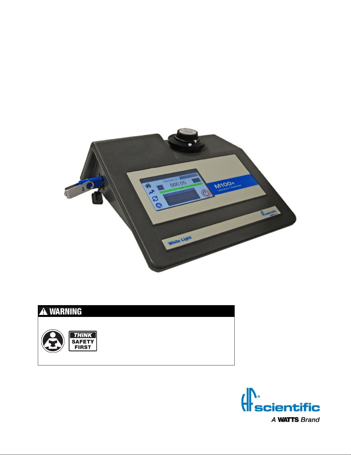
M100+
Models 28060 & 28061
Laboratory Turbidimeter
M100+ (January 2019)
Rev. 1.74
Read Manual and all product labels BEFORE
using the equipment. Do not use unless you
know the safe and proper operation of this
equipment. Keep this Manual available for
easy access by all users. Replacement
Manuals are available at HFscientific.com
3170 Old Metro Parkway
Ft. Myers, FL 33916
Phone: 239-337-2116
Fax: 239-332-7643
Toll-free: 888-203-7248
E-Mail: HF.Info@WattsWater.com
Page 2

M100+ (January 2019)
Rev. 1.74
Page 3
M100+ (January 2019)
Rev. 1.74
Page 4

M100+ (January 2019)
Rev. 1.74
Page 5

Attention Owners and Users
Model:
Date of purchase:
Thank you for purchasing the M100+™ turbidimeter. This equipment will provide safe
and productive operation as long as it is installed, used, maintained, and serviced in
accordance with the instructions in this manual and is properly maintained. Importantly,
unless the user is adequately trained and supervised, there is a possibility of personal
injury, property damage or damage to the equipment.
Owners and users of this equipment bear the responsibility to make certain that this
equipment is used properly and safely. READ THIS MANUAL carefully, learn how to
use and service this equipment correctly, and strictly follow all of the instructions
contained in this manual and the requirements of local, state and federal law. Failure to
do so could result in personal injury, property damage or damage to the equipment. This
manual should be considered a permanent part of your machine and should be kept
available for easy reference by any user.
Owners should not permit anyone to touch this equipment unless they are over 18 years
of age, are adequately trained and supervised, and have read and understood this
manual. Owners should also ensure that no unauthorized personnel comes in contact
with this equipment.
If this equipment, or any of its parts, becomes damaged or needs repair, stop using the
equipment and contact an experienced service individual immediately. If the warning
labels or this manual are misplaced, damaged or illegible, or if you require additional
copies, please contact customer service at +1 (239) 337-2116 or 888-203-7248 for these
items at no charge.
Please remember that this manual and the warning labels do not replace the need to be
alert, to properly train and supervise users, and to use common sense when using this
equipment.
If you are ever uncertain about a particular task or the proper method of operating this
equipment, ask your supervisor, consult this manual, access www.hfscientific.com, or
contact us at 888-203-7248.
PRODUCT IDENTIFICATION
Please record your product’s identification and purchase information which will help in
the event you have questions or need any service.
Serial #:
M100+ (January 2019)
Rev. 1.74
Seller name/address:
Page 6

Table of Contents
Section Page
Understanding Safety Information .............................................................................................................. 1
Specifications ............................................................................................................................................. 2
1.0 Overview ............................................................................................................................................ 3
1.1 The M100+ Product Description .................................................................................................... 3
2.0 Unpacking and Inspection ................................................................................................................. 4
3.0 Site Selection ..................................................................................................................................... 5
4.0 Setup, Configuration and Calibration ................................................................................................. 5
4.1 Operating Screens ........................................................................................................................ 6
4.2 Configuring the M100+ .................................................................................................................. 7
4.2.1 Screen Brightness ................................................................................................................ 8
4.2.2 Auto/Manual Readings ......................................................................................................... 8
4.2.3 Auto Power Down ................................................................................................................. 9
4.2.4 Touch Screen Calibration ..................................................................................................... 9
4.2.5 Set Date/Time ..................................................................................................................... 10
4.2.6 Delete Samples .................................................................................................................. 10
4.2.7 Data Resolution .................................................................................................................. 11
4.2.8 Offset .................................................................................................................................. 11
4.2.9 Device ID ............................................................................................................................ 11
4.2.10 Calibration Reminder ...................................................................................................... 12
4.2.11 Calibration Download ..................................................................................................... 12
4.2.12 Firmware Update ............................................................................................................ 13
4.2.13 Reset Defaults ................................................................................................................ 13
4.2.14 About Device .................................................................................................................. 14
4.3 Calibrating the M100+ ................................................................................................................. 14
4.3.1 Calibration Standards ......................................................................................................... 15
4.3.2 Care of ProCal Standards .................................................................................................. 16
4.3.3 Indexing Calibration Cuvettes ............................................................................................. 16
4.3.4 Calibration Procedures ....................................................................................................... 17
4.3.5 Alternate Calibration Ranges .............................................................................................. 19
4.3.6 Failed Calibration ................................................................................................................ 19
5.0 Operation ......................................................................................................................................... 20
5.1 Home Screen............................................................................................................................... 20
5.2 Trend Screen ............................................................................................................................... 21
5.3 Data Retrieval .............................................................................................................................. 21
5.3.1 USB Connection ................................................................................................................. 22
6.0 Troubleshooting ............................................................................................................................... 23
6.1 M100+ Fault Detection ................................................................................................................ 23
6.2 Diagnostic Table .......................................................................................................................... 23
6.3 Technical and Customer Assistance ........................................................................................... 23
7.0 Routine Maintenance ....................................................................................................................... 25
7.1 Cleaning the Cuvette ................................................................................................................... 25
7.2 Replacing the Source Lamp ........................................................................................................ 25
7.3 Battery ......................................................................................................................................... 25
8.0 Accessories and Replacement Parts List ........................................................................................ 26
9.0 Limited Warranty .............................................................................................................................. 27
M100+ (January 2019)
Rev. 1.74
Page 7
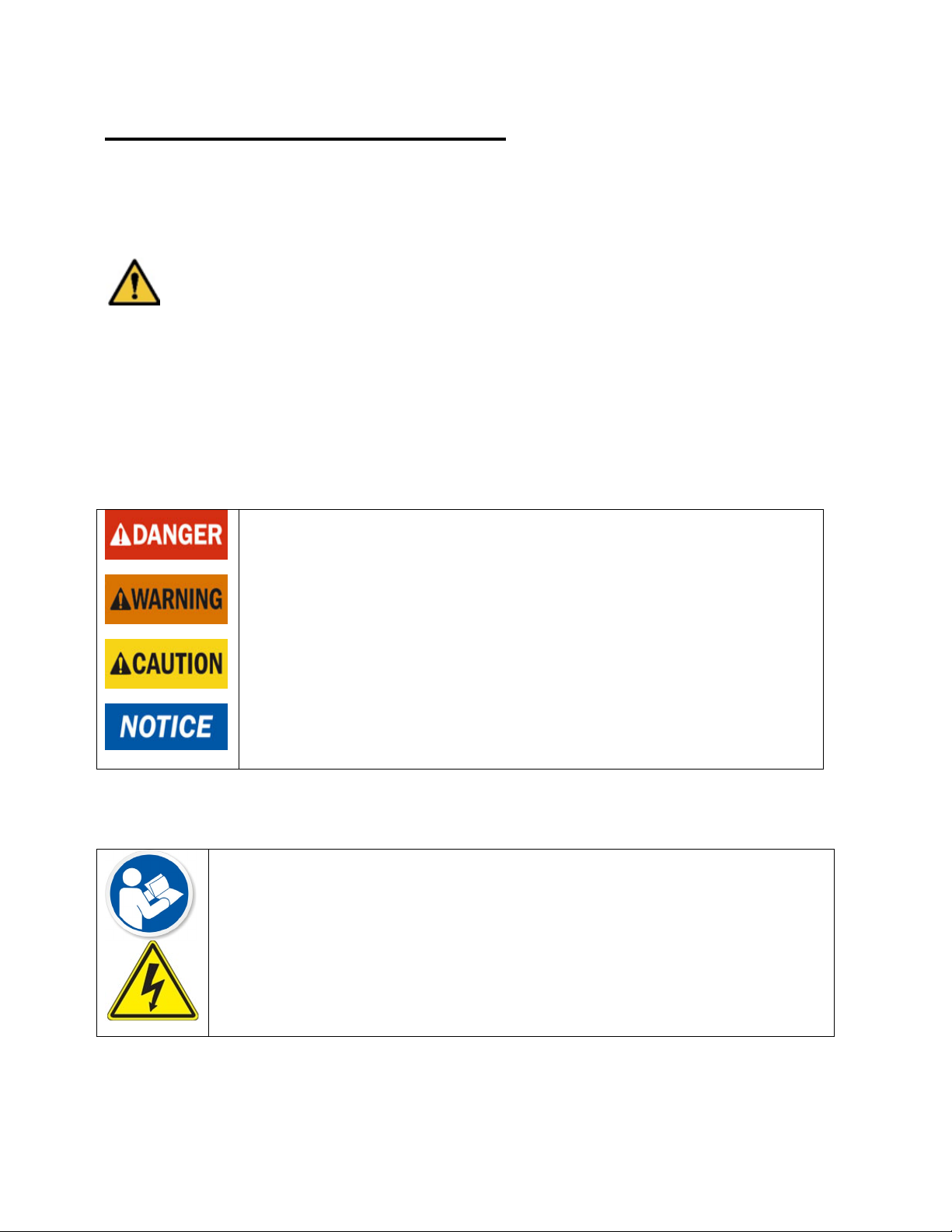
Understanding Safety Information
Identifies hazards which, if not avoided, will result in death or serious
Identifies hazards which, if not avoided, could result in death or
Identifies hazards which, if not avoided, will result in minor or
Identifies practices, actions or failure to act which will result in
This manual contains safety and use instructions that must be followed during the
installation, commissioning, operation, care and maintenance, and service of the M100+.
All responsible personnel must read this manual prior to working with this instrument and
should familiarize themselves with the following safety symbols, signals, and pictorials.
This is a safety-alert symbol.
• The safety alert symbol is shown alone or used with a signal word (DANGER,
WARNING or CAUTION), a pictorial and/or a safety message to alert you to
hazards.
• When you see this symbol alone or with a signal word on this instrument or in this
Manual, be alert to the potential for death or serious personal injury.
Safety signal words have the following meaning:
injury.
serious injury.
moderate injury.
property damage or damage to the equipment.
Pictorials used on the equipment and in this Manual have the following meanings:
This pictorial alerts you to the need to read the Manual.
This pictorial alerts you to electricity, electrocution and shock hazards.
1
Page 8
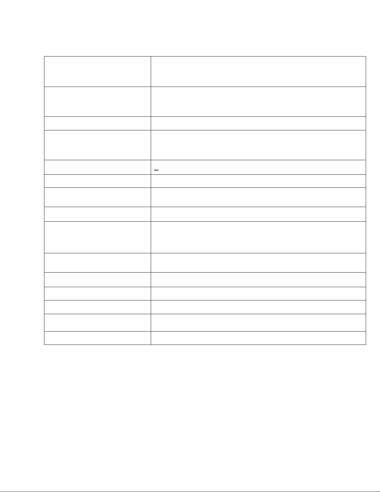
Specifications
forth in EPA method 180.1
lamp.
This model uses an IR
LED lamp.
±2% of reading or ±0.02 NTU below 40 NTU whichever is
±5% of reading above 40 NTU
new firmware via thumb drive (USB flash stick).
3. Three Year Battery Backup With no External Power
Range
Sample Temperature Range
0°C – 40°C (32°F – 104°F)
Dimensions
237mm W x 254mm L x 121mm H (10.75” W x 10” L x 4.75” H)
Shipping Weight
2.5 kg (5.5 lbs.)
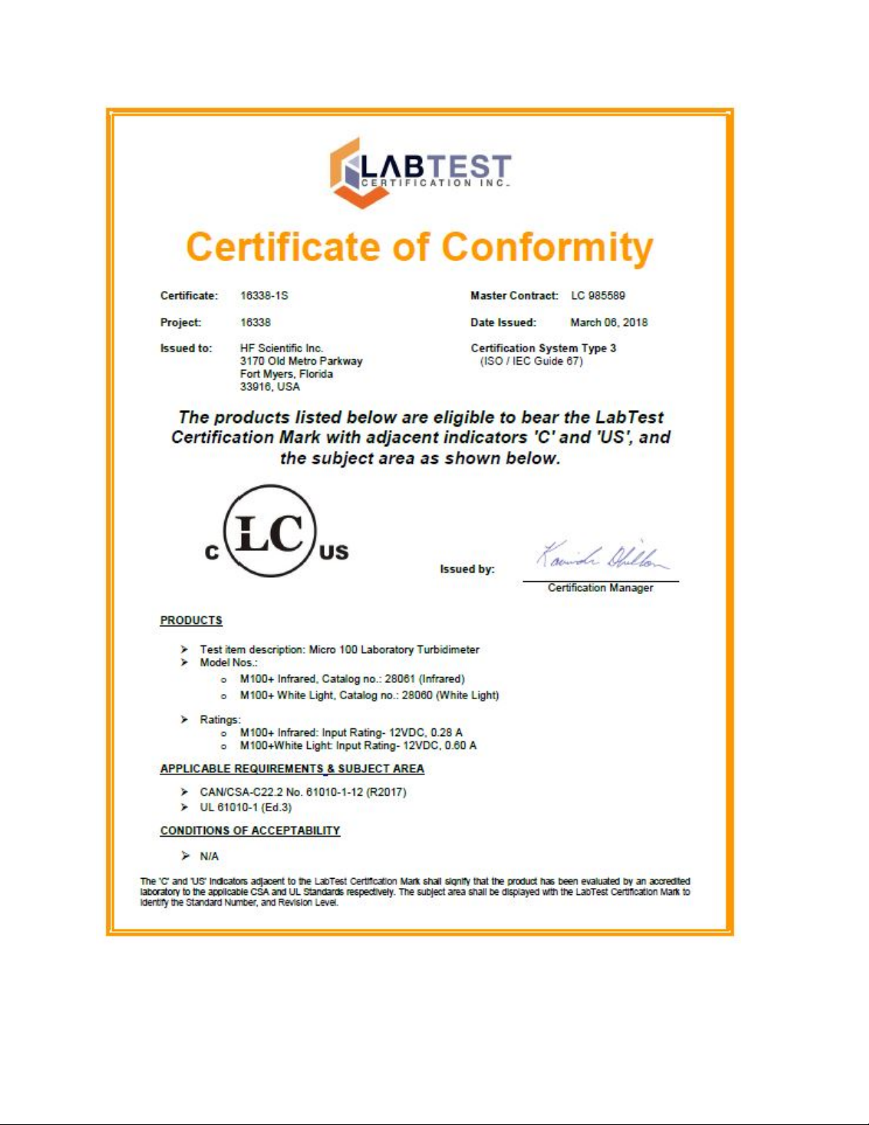
Certifications
LC mark tested to UL and CSA.
Conforms to CE
Warranty
1 Year from date of shipment
M100+ White Light
Model 28060
M100+ Infrared
Model 28061
Measurement Range
Accuracy
†, ††
Repeatability††
Resolution
USB
Power Supply
Miscellaneous
Specifications
Conforms to specifications set
(Nephelometric Method)
§ This Model uses a tungsten filament
Conforms to specifications set forth in ISO 7027: Water
Quality - Determination of Turbidity.
0-4000 NTU
greater
< ±1% of reading or ± 0.02 NTU whichever is greater
Menu settable up to 0.0000 over the entire range
Printer or download logged data & calibration data & upload
UL, CSA & CE approved 12V DC, Wall Mount
1. USB port for logged data download and software updates.
2. Built-in Diagnostics
Operating Temperature
§
The specifications found in EPA method 180.1 are essentially the same as the specifications set out in method 2130B of the Standard
Methods for the Examination of Water and Wastewater 22
The M100 PLUS meets or exceeds, the specifications set forth in these methods.
1°C – 40°C (34°F – 104°F)
nd
edition and the specifications set out in ASTM Standard Method D1889-94.
†
Instrumental accuracy measured under controlled laboratory conditions at 25°C (77°F)
††
Both the accuracy and repeatability specifications for the M100+ are valid only for measurement of static (non-flowing) samples.
2
Page 9
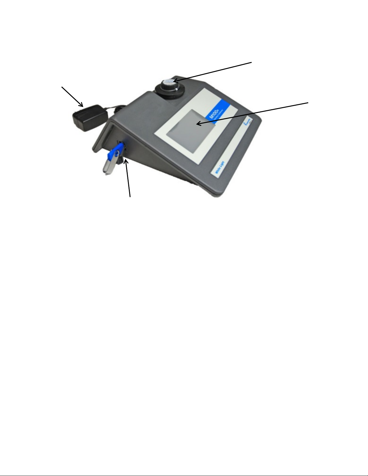
1.0 Overview
Power Supply
Touch screen
Standard Inserted in Optics
USB Connector
1.1 The M100+ Product Description
The M100+ is a process turbidimeter that allows for the laboratory measurement
of the turbidity of sample water. The white light M100+ has been designed to meet
the design criteria specified by the US EPA 180.1 on turbidity measurement. The
infrared M100+ was designed to meet the design criteria specified in ISO 7027
and DIN 27027 for the measurement of the turbidity of a sample. Both models
have long life lamps.
The M100+ instruments are equipped with a USB slot in order to download logged
data and calibration information and to update operating software.
The M100+ is equipped with a color touch screen for easy and efficient operation.
3
Page 10
2.0 Unpacking and Inspection
Item
Quantity
(shipped in a separate box to ensure freshness)
The table below indicates the items in the turbidimeter shipment.
M100+ Laboratory Turbidimeter
Accessory Kit for M100+ (2 empty sample cuvettes with caps)
Full Range Calibration Kit High Range A, High Range B, 1000 NTU,
10 NTU & 0.02 NTU
Quick Start Guide
Flash Drive Containing Full Owner’s and User’s Manual
Wall Mount Power Supply with Ferrite
A ferrite is included with the power supply. This should be looped twice
through the cord near the side that connects to the instrument to eliminate EMI
interference.
Remove the instrument from the packing carton. Carefully inspect all items
to ensure that no visible damage has occurred during shipment. If the items
received do not match the order, please immediately contact the local distributor
or the HF scientific Customer Service department.
1
1
1
1
1
1
4
Page 11

3.0 Site Selection
The M100+ must be used in a suitable dry location with adequate ventilation. It
should not be located where chemicals such as chlorine are located. It must be operated
and stored between 1 and 40°C. The instrument should be used on a stable table top
and less than 90 cm (3 feet) from a power source.
Power Requirements:
• The M100+ requires 12VDC for proper operation. The provided supply is rated at
1A.
• The M100+ is supplied with a wall mount power supply intended for operation with
100-240 VAC, 47-63 Hz power source. BEFORE installing, verify that the line
voltage falls within these specifications.
• Connect the wall mount power supply to the rear panel of the M100+.
• An optional Euro wall mount power supply is available.
4.0 Setup, Configuration and Calibration
Before using your M100+, you will need to familiarize yourself with the
instrument’s operating modes and functions and perform some setup, configuration, and
calibration.
• The M100+ allows for the measurement of the turbidity of water. The
turbidity of the water is usually reported in Nephelometric Turbidity Units
(NTU) but may be reported in Formazin Nephelometric Units (FNU). This
is user selectable.
• Readings up to 4400 are possible but readings above 4000 are outside of
the rated specifications. Readings above 4400 NTU will cause the display
to flash indicating an over-range condition.
• During normal operation, the instrument will be at the HOME screen. This
is this screen where measurements can be viewed.
• Please note, some features depicted in this manual may change with
future firmware updates.
5
Page 12

Home ( ) screen is the normal reading
Trend ( ) screen is used for displaying
a serial printer.
Calibration ( ) screen is used for
specifications.
Setup ( ) screen is where configuration
according to needs and preferred
operation at any time during normal
menus to facilitate
instrument configuration. This is also
where logged files and calibration logs
can be downloaded and where new
software, when available, can be
uploaded.
4.1 Operating Screens
There are four main operating screens in the form of Icons, Home ( ),
Trend ( ), Calibration ( ), and Setup ( ). To change between screens,
simply touch the appropriate icon.
screen. This is the default mode when
power is applied or restored. The other
three operation screens are limited to 15
minutes with no key presses after which
the screen will return to Home.
trend information. This information can be
downloaded to the USB stick or printed to
calibration. The instrument was
calibrated and tested prior to leaving the
factory. Therefore, it is possible to use
the instrument directly out of the box.
Under normal conditions, re-calibration is
required once every three months.
Quarterly calibration ensures
performance within accuracy
changes can be made. In the Setup
screen, you can customize the instrument
operation. The Setup screen has been
split into sub-
6
Page 13

4.2 Configuring the M100+
The M100+ has been designed to provide the ability to customize the instrument
according to your needs at any time during normal operation. The Setup screen
has been split into sub-menus to facilitate instrument configuration. This section
describes how to use each of the sub-menus to configure the instrument.
Turn Power “ON:” After confirming that the M100+ is safely and properly
plugged into a suitable power source, simply touch the screen to turn the
instrument on. Depending on the setting, the instrument will usually power down
automatically.
There is a setting (Auto Power Down) that allows the instrument to
stay on and require a manual shut down. An On/Off button will appear
on the Home screen. It is not recommended to leave the instrument on constantly
as it may cause drift and premature degradation of the lamp. The drift can be
corrected by more frequent calibrations.
The following configuration settings can be performed in the Setup
screen:
• Screen Brightness
• Auto/Manual Readings
• Auto Power Down
• Touch Screen Calibration
• Set Time/Date
• Delete Samples
• Data Resolution
• Offset
• Device ID
• Calibration Reminder
• Calibration Download
• Log Download
• Firmware Update
• Reset Defaults
• About Device
The Setup screen has quite a few menu selections. Use the slider on the righthand side to access to all of the selections.
• At any time any of the Home, Trend, Calibration and Setup screens can be
pressed and implemented.
• To select any of the Setup options identified below, press Setup icon and then
select the option that you wish to change.
7
Page 14

4.2.1 Screen Brightness
• Press the Setup icon. Select Screen Brightness.
• Adjust current Screen Brightness.
• Use & or the drag cursor.
• Push to save and return to Setup Menu.
4.2.2 Auto/Manual Readings
• Press the Setup icon. Select Auto/Manual Readings.
• In this screen, a selection can be made of continuous readings (Auto) or for
a single reading (Manual).
• If Auto is selected the rate of updates can be selected from 1 to 60
seconds using the & buttons.
• Select to save and confirm.
• If Manual is chosen, a button will appear in the Home icon to take
readings.
• Manual readings take approximately 10 seconds to display. It will say
“capturing” to indicate that it is processing.
8
Page 15

4.2.3 Auto Power Down
• Press the Setup icon. Auto Power Down.
• The M100+can be set to power down automatically.
• The factory setting is to power down after 30 minutes.
• To save lamp life it is recommended that auto power down is used.
• The time can be adjusted using the & buttons.
• If you need to keep the instrument on you can select OFF for the Auto
Power Down. In this case, you will turn the M100+ off using the button
on the Home screen.
4.2.4 Touch Screen Calibration
• Press the Setup icon. Select Touch Screen Calibration.
• This has been factory adjusted.
• Adjust if the alignment is needed.
• May need to be done if new software downloaded.
• Five position setup.
• If this calibration fails. Restart by pulling and reinserting the power plug.
Press top screen time banner for 5 seconds to reset to factory default
screen setting. Then attempt the calibration again.
9
Page 16

4.2.5 Set Date/Time
• Press the Setup icon. Select Set Date/Time.
• Date/Time: Set the date and time by using the & buttons.
When complete, press the to save the setting and return to Setup menu.
• Time Format: Allows you to select 12 or 24 hour time. This menu will
change slightly if the 24-hour format is selected. Use the & buttons to
select your option.
• Daylight Saving Time: Allows you to enable Daylight Saving Time in
the USA, Canada and other countries that follow the US Energy Savings
Act of 2005.
4.2.6 Delete Samples
• Press the Setup icon. Select Delete Samples.
• Select either All or By Sample ID.
• If Sample ID is selected, select sample.
• Press to delete sample.
10
Page 17

4.2.7 Data Resolution
• Press the Setup icon. Select Data Resolution.
• Sets the resolution or number of digits after decimal point shown in Home
screen.
• Use & to set the resolution. The screen shows a representation.
• Push to save and return to Setup Menu.
4.2.8 Offset
• Press the Setup icon. Select Offset.
• Adjusts the reading slightly to allow for agreement with another instrument.
• Turn On to use then use the & buttons to set the offset.
• Allowable resolution is -1.00 to +1.00 in increments of 0.01 NTU
4.2.9 Device ID
• Press the Setup icon. Select Device ID.
• Sets the Device ID for data logging purposes.
• Touching the number box brings up and keypad. Enter the number on the
keypad and press the .
• This returns to screen above. If this is acceptable press .
• If this is not acceptable press the .
11
Page 18

4.2.10 Calibration Reminder
• Press the Setup icon. Select Calibration Reminder.
• Sets how often a calibration reminder comes up on Home screen.
• The USEPA recommends calibration every quarter (90 days).
• Use the & buttons to set period in days.
• Set to OFF if not desired.
• Push to save and return to Setup Menu.
4.2.11 Calibration Download
• Press the Setup icon. Select Calibration Download.
• Allows USB thumb drive download of calibration history.
• Insert USB thumb drive into the USB port.
• Push to transfer the information and return to the Setup screen.
• See Data Retrieval section 5.3 for more information.
12
Page 19

4.2.12 Firmware Update
• Press the Setup icon.
• This screen is used to update firmware via USB.
• Insert the USB thumb drive containing the software into the USB port.
• Push to continue.
• If the inserted USB thumb drive contains a lower revision number than that
currently installed, then the M100 will ask if you are sure you want to
continue.
• Push to continue.
• The upload will take several minutes. During the initial upload, the screen
will show “busy” and screen anomalies may appear until the upload is
complete.
• Finally, the screen will turn off when complete.
• Any firmware updates will be posted to our website www.hfscientific.com.
• The current firmware version is shown in About Device. See 4.2.16 below.
4.2.13 Reset Defaults
• Press the Setup icon.
• This menu allows resetting the calibration and/or settings. This clears the
calibration and new calibration will be required to operate the instrument.
• Settings may change so these should be checked.
13
Page 20

4.2.14 About Device
• Press the Setup icon.
• This menu shows the current setting of the Device ID, the lamp type, and
the firmware revision number.
• Firmware revision can be compared to available firmware on the website.
• Push to continue.
4.3 Calibrating the M100+
• The instrument was calibrated and tested prior to leaving the factory.
Therefore, it is possible to use the instrument directly out of the box. Under
normal conditions, re-calibration is required once every three months.
Quarterly calibration ensures performance within accuracy specifications.
The EPA and ISO recommend that on-line turbidimeters be
calibrated with a primary standard at least once every three
months if they are to be used for reporting purposes.
14
Page 21

4.3.1 Calibration Standards
• If the M100+ will be used over the entire range of 0.02 to 4000 NTU, a
complete calibration as described below will be required which includes the
two High Range standards.
• If instrument accuracy is only required below 1000 NTU, a calibration may
be performed using the 1000 NTU standard, the 10 NTU standard, and
0.02 NTU standard. To calibrate starting at 1000 NTU, simply press the
1000 button on the calibration screen.
• If instrument accuracy is only required below 10 NTU, such as for potable
water, a calibration may be performed using only a 10 NTU and a 0.02
NTU standard. To calibrate starting at the 10 NTU, simply press the 10
button on the calibration screen.
• We recommend that the following materials be used during calibration to
achieve the full-scale accuracy stated in this manual:
High Range A ProCal Calibration Standard available from HF scientific
High Range B ProCal Calibration Standard available from HF scientific
1000 NTU ProCal Calibration Standard available from HF scientific
10.0 NTU ProCal Calibration Standard available from HF scientific
0.02 NTU ProCal Calibration Standard available from HF scientific
is used to calibrate the instrument, ensure that a fresh stock suspension of
Formazin is used to achieve the accuracy quoted for the instrument.
A Formazin Stock Solution Kit is available from HF scientific (Catalog No.
50040).
The HF scientific ProCal, primary calibration standards (refer to section 8.0
Accessories and Replacement Parts List), are more stable than Formazin
and have a minimum shelf life of 12 months. Prior to recalibration, review
the expiration dates, to ensure that the standards have not expired.
It is well known that diluted Formazin is unstable. If Formazin
15
Page 22

4.3.2 Care of ProCal Standards The information below is provided as a general guidelines for the proper care of ProCal standards.
• ProCal standards should only be handled by the top, black cap or by the
very bottom of the cuvette.
• Keep the cuvette glass clean of fingerprints and debris.
• Cuvettes can be cleaned with any domestic glass cleaner and the provided
microfiber cloth.
• Prevent ProCal standards from freezing. This will most likely destroy them.
• Standards under 100 NTU must be freshly poured from the supplied bottle
as they are are not stable in the glass cuvette.
• There are no need to shake standards, but standards over 1000 NTU
should be upended gently before use.
• Replace standards at the expiration date.
4.3.3 Indexing Calibration Cuvettes To achieve the greatest accuracy, and account for normal scratches and aberrations in cuvette glass when calibrating, HF Scientific recommends indexing the cuvettes.
Standards and standard kits purchased from HF
Scientific are supplied with indexing rings. Complete
instructions regarding how to index the cuvettes are
included in the calibration kits.
The following steps allow repeatable indexing of calibration standards:
1. With the instrument in the Home screen, insert the standard.
2. Indexing is best performed if the automatic reading is enabled and set
to 1 sec/reading. See section 4.2.2 for more information on
Auto/Manual Readings.
3. Slowly rotate the standard, inside the optical well, one complete
revolution (360º). While rotating the standard slowly, observe the
measured turbidity and locate the position of the cuvette having the
lowest reading.
4. With the calibration standard positioned at the location having the
lowest turbidity reading, install the Indexing Ring over the cap on the
standard so that the pointer of the Indexing Ring faces directly forward.
When using the standards in the future, always insert the standard so that
the pointer of the indexing ring faces forward. Slowly rotate the standard
back and forth about 5° to find the lowest point. The standard is now
indexed and ready for use.
16
Page 23

4.3.4 Calibration Procedures
Select Range
Command button:
calibration.
Formazin Calbration Screen
ProCal Calibration Screen
• Select the calibration function of the instrument by pressing the Calibrate
icon.
• Select the appropriate calibration standard - either Formazin or ProCal then press .
• The calibration menu will be displayed as shown above.
• On the left-hand side are selections for the range for calibration. Select the
highest value required for your application.
• Ensure standards are indexed as described in section 4.3.3 prior to
calibration.
• The calibration standards should be cleaned with a microfiber cloth and
any standard window cleaner solution.
• Handle standards only by the black cap to prevent fingerprints or other
smudges from affecting the readings.
• Have the standards prepared for the range you intend to calibrate.
• To calibrate for 0-4000 NTU using ProCal, you will need the High Range A,
High Range B, 1000 NTU, 10 NTU, and 0.02 NTU standards.
• To calibrate for 0-4000 NTU using Formazin, you will need the 4000 NTU,
1000 NTU, 10 NTU, and 0.02 NTU standards.
• The command button will guide you through the calibration.
Follow directions
that appear here for
17
Page 24

Calibration steps (Using ProCal):
1. Press the High Range A button on the left side of the screen.
2. Insert the High Range A standard.
3. Press the Command button in the middle of the screen to start the
calibration.
4. A countdown will appear from 30.
5. When the count is complete the screen will request the High Range B.
6. Press the High Range B button on the left side of the screen.
7. Insert the High Range B standard.
8. A countdown will appear from 30.
9. When the count is complete the screen will request the 1000 NTU.
10. Insert the 1000 NTU standard.
11. Press the Command button start the calibration of the 1000 NTU.
12. A countdown will appear from 60.
13. When the count is complete the screen will request the 10 NTU.
14. Insert the 10 NTU standard.
15. Press the Command button start the calibration of the 10 NTU.
16. A countdown will appear from 60.
17. When the count is complete the screen will request the 0.02 NTU.
18. Insert the 0.02 NTU standard.
19. Press the Command button start the calibration of the 0.02 NTU.
20. A countdown will appear from 30.
21. When complete, all the buttons on the left should be all green and the
Command button should say Calibration Good
Calibration steps (Using Formazin):
1. Press the 4000 button on the left side of the screen.
2. Insert the 4000 NTU standard.
3. Press the Command button in the middle of the screen to start the
calibration.
4. A countdown will appear from 30.
5. When the count is complete the screen will request the 1000 NTU.
6. Insert the 1000 NTU standard.
7. Press the Command button start the calibration of the 1000 NTU.
8. A countdown will appear from 60.
9. When the count is complete the screen will request the 10 NTU.
10. Insert the 10 NTU standard.
11. Press the Command button start the calibration of the 10 NTU.
12. A countdown will appear from 60.
13. When the count is complete the screen will request the 0.02 NTU.
14. Insert the 0.02 NTU standard.
15. Press the Command button start the calibration of the 0.02 NTU.
16. A countdown will appear from 30.
17. When complete, all the buttons on the left should be all green and the
Command button should say Calibration Good
18
Page 25

4.3.5 Alternate Calibration Ranges
• Alternately you could choose to calibrate to 1000 NTU, which requires
1000 NTU, 10 NTU, and 0.02 NTU. Press the 1000 button on the left side
and start at step 5 above.
• A calibration for the only the 10 NTU range requires only the 10 NTU and
0.02 NTU. Press the 10 button on the left side and start at step 9 above.
• For the two alternate ranges, these will still read the full range with a
reduced accuracy above the range of calibration.
4.3.6 Failed Calibration In the case of a failed calibration, the last good calibration is restored once the user exits to the Home Screen. A failure will be evident at the calibration screen will show all red.
The instrument can be used with this calibration with a potentially reduced
accuracy. The bad calibration will be noted in the calibration log and as a
reminder, a yellow diagnostic banner will show on the home screen
indicating that the last calibration had failed and that the instrument was
using the previous calibration. The only way to remove this indication is to
successfully complete a calibration.
Check the standards for cleanliness and expiration date. If everything looks
good, attempt the calibration again. If the calibration fails after the second
attempt, the most likely causes are that standards are bad or the lamp
needs replacement.
19
Page 26

5.0 Operation
Calibration
On/Off
Sample ID (Name)
NTU/FNU
Reading List
Current Reading
Update Reading
Time
Diagnostic Banner
Home
Setup
Trend
5.1 Home Screen
All operations start on the Home screen. Refer to the above figure for all
operations.
• When the instrument is in Automatic Readings (section 4.2.2.), Update
Reading button will not show. This is used only for manual updates.
• The current reading is always shown in the large number format.
• Toggle between NTU & FNU by touching the button.
• Pressing Sample ID brings up a keypad to allow you to provide a name.
• Sample ID shows up to five previous readings. All readings are saved. See
Trend screen below.
• The instrument can be turned off manually even if Auto Power Down is
selected.
20
Page 27

5.2 Trend Screen
Screen Selection
Sample ID
Selection
Time
Download/Print
Graph
To get session
readings
• Select Sample ID first.
• After a reading session in the Home screen, if Trend screen is
selected, the Reading List from the Home screen is cleared but this
information is now saved under Sample ID in the Trend screen. If a
new session is started in the Home screen under the same Sample
ID the readings will be appended to the session readings.
• The axis scaling of the Sample graph can be adjusted in Chart
Range & Options (see section 4.2.4).
• If a USB thumb drive is connected, Session Readings shown will be
transferred to the flash drive after pressing Download/Print.
• If USB printer is connected, Session Readings shown will be printed
after pressing Download/Print.
• Sample ID will be saved until deleted. See Delete Samples section
4.2.7.
5.3 Data Retrieval
• All data is saved in CSV format and is date & time stamped.
• There are several methods to download particular information.
• Sample ID Data can be downloaded to a USB thumb drive or printed in the
Trend screen after pressing Download/Print.
• Calibration data can be downloaded into an inserted USB thumb drive in
the Calibration Download menu after pressing the button. See section
4.2.12 for more information on Calibration Download
• Logged data can be downloaded to an inserted USB thumb drive in the Log
Download menu after pressing the button. See section 4.2.13 for more
information on log download.
21
Page 28

5.3.1 USB Connection
The M100+ has two USB connections, a USB-A on the side and a
USB-B on the back. Only the side connection is active at this time. The USB-B at
the back of the instrument may be used in a future firmware update.
The USB-A connection can be used to upload new software or download
logged data and calibration reports via a USB thumb drive.
Firmware uploads (updated firmware) can be made by loading the firmware
onto a USB thumb drive and inserting it into the USB-A connector. The
update will not affect configurations or stored data; however it always
advisable to check the configuration as menus may change.
To upload firmware:
• See section 4.2.14 for more information on firmware
updates.
for software updates.
To keep the USB contacts from getting contaminated a
USB plug cover is provided. It is recommended that
this cover is replaced whenever the USB is not being
used.
A USB- Type B plug is provided at the back. This is currently not
active but was supplied for a potential future update. Keep the
supplied plug in place to prevent damage.
• Check our website
22
Page 29

6.0 Troubleshooting
Symptom
Cause
Cure
Clean the inside and outside of the
deionized water. Do not shake
samples.
thumb drive is not fully
Bubbles in solution
See readings higher than expected
above.
Incorrect screen calibration
Hold upper (time) banner on any screen
for 5 seconds to load default screen
shown in section 4.2.5
6.1 M100+ Fault Detection
The M100+ performs continuous diagnostic monitoring. The diagnostic indicator in
the Home screen will display any errors or warnings in writing.
• A green indicator shows that everything is good.
• A red indicator denotes an error.
• Potential errors are a bad lamp or the reading is taking place in a band that
has not been calibrated.
• A yellow indicator is a warning and could show either faulty database or the
device plugged into the USB is incompatible
Bubbles in solution
Readings are higher than expected
USB download not working
Readings are erratic
Readings are lower than expected Instrument out of calibration Recalibrate. Refer to section 4.3
Screen calibration not working
Instrument out of calibration Recalibrate Refer to section 4.3
Check
inserted
Thumb drive is not formatted
stored
cuvette with a detergent solution. Rinse
with
Insert USB thumb drive fully
Format to FAT32
calibration then go to calibrate screen as
6.2 Diagnostic Table
6.3 Technical and Customer Assistance
If for any reason assistance is needed regarding this instrument please do not
hesitate to contact either the HF scientific Technical Service Department or the
HF scientific Customer Service Department for parts orders.
HF scientific
3170 Old Metro Parkway
Fort Myers, Florida 33916-7597
Phone: (239) 337-2116 Fax: (239) 332-7643
Toll-free: 888-203-7248
23
Page 30

Email: HF.Info@Wattswater.com
www.hfscientific.com
24
Page 31

7.0 Routine Maintenance
Routine maintenance includes calibration, as mentioned, in section 4.3 and
cleaning of the cuvettes.
7.1 Cleaning the Cuvette
Measurement cuvettes used for the sample should be clean and free of marks or
scratches.
Cleaning is accomplished by cleaning the interior and exterior with a detergent
solution and then rinsing several times with distilled or deionized water. Ensure
the cuvettes are clean prior to use.
If cuvettes become scratched or stained they should be replaced. Replacement
cuvettes are available from HF scientific your local HF scientific agent. Use Cat #
50051pack of 3 cuvettes with caps or 50052 for a pack of 10 cuvettes with caps.
7.2 Replacing the Source Lamp
The Infrared and White Light source lamps in the M100+ instruments are
designed for long life. These lamps, however, are not covered by the warranty. If
the lamp should need replacement, we recommend calling HF Service
Department for assistance. These can also be purchased with instructions to
change. Calibration will be required if a lamp change is made.
7.3 Battery
This instrument uses a battery for back up of the clock feature with an expected
life of over 3 years. The battery is non-rechargeable and no attempt to charge it
should be made. If the battery needs to be replaced contact HF scientific and
arrange for service.
25
Page 32

8.0 Accessories and Replacement Parts List
ProCal
ProCal
ProCal
The items shown below are recommended accessories and replacement parts.
Accessory Cat. # Photo
Replacement Lamp Assembly White Light with
Instructions
Replacement Lamp Assembly IR Light with
Instructions
Operating Manual, M100+ 29293 N/A
Calibration Kit, .02, 10 & 1000 NTU
Calibration Kit, .02, 10, 1000,
High Range A & High Range B
24082S
21369S
39957
39940
Calibration Standard 10 NTU 125ml
Formazin Stock Kit 50040 N/A
Formazin Stock Solution, 4000 NTU, 500 ml
Replacement Cuvette – 3 Pack
Replacement Cuvette – 10 Pack
39825
70914
50051
50052
26
Page 33

9.0 Limited Warranty
HF scientific inc., as a vendor, warrants to the original purchaser of this instrument that it will be
free of defects in material and workmanship, in normal use and service, for a period of one year
from date of invoice. HF scientific inc.’s obligation under this warranty is limited to replacing, at
its factory, the instrument or any part thereof. Parts, which by their nature are normally required
to be replaced periodically, consistent with normal maintenance, specifically reagent, desiccant,
sensors, lamps, and fuses are excluded. Also, excluded is accessories and supply type items.
The original purchaser is responsible for the return of the instruments, or parts thereof, to HF
scientific’ inc.’s factory. This includes all freight charges incurred in shipping to and from HF
scientific inc.’s factory.
HF scientific inc .is not responsible for damage to the instrument, or parts thereof, resulting from
misuse, environmental corrosion, negligence or accident, or defects resulting from repairs,
alterations or installation made by any person or company not authorized by HF scientific inc.
The remedy described in the first paragraph of this warranty shall constitute the sole and
exclusive remedy for breach of warranty. HF scientific inc. assumes no liability for incidental,
consequential or special damage of any kind, and the original purchaser, by placement of an order
for the instrument, or parts thereof, shall be deemed liable for any and all damages incurred by the
use or misuse of the instruments, or parts thereof, by the purchaser, its employees, or others,
following receipt thereof.
Carefully inspect this product for shipping damage, if damaged, immediately notify the shipping
company and arrange an on-site inspection. HF scientific inc cannot be responsible for damage in
shipment and cannot assist with claims without an on-site inspection of the damage.
This warranty is given expressly and in lieu of all other warranties, expressed or implied.
Purchaser agrees that there is no warranty on merchantability or fitness for a particular purpose
and that there are no other warranties, expressed or implied. HF scientific inc hereby specifically
disclaims all other warranties, express or implied. No agent is authorized to assume for HF
scientific inc., any liability except as set forth above. Some States do not allow limitations on how
long an implied warranty lasts, and some States do not allow the exclusion or limitation of
incidental or consequential damages.
Therefore the above limitations may not apply to you. This
Limited Warranty gives you specific legal rights, and you may have other rights that vary from
State to State. You should consult applicable state laws to determine your rights. SO FAR AS IS
CONSISTENT WITH APPLICABLE STATE LAW, ANY IMPLIED WARRANTIES THAT MAY NOT
BE DISCLAIMED, INCLUDING THE IMPLIED WARRANTIES OF MERCHANTABILITY AND
FITNESS FOR A PARTICULAR PURPOSE, ARE LIMITED IN DURATION TO ONE YEAR FROM
THE DATE OF ORIGINAL SHIPMENT.
HF scientific, Inc.
3170 Old Metro Parkway
Fort Myers, Florida 33916-7597
Phone: (239) 337-2116
Fax: (239) 332-7643
Toll-free: 888-203-7248
Email: HF.Info@Wattswater.com
Website: www.hfscientific.com
27
 Loading...