

Page 1

OWNER’S MANUAL
CLX OnLine Residual
Chlorine Monitor
HF scientific
3170 Old Metro Parkway
Ft. Myers, FL 33916
Phone: 239-337-2116
Fax: 239-332-7643
Toll Free: 888-203-7248
Email: HF.Info@Wattswater.com
Website: www.hfscientific.com
Catalog #24420 (4/18)
REV 6.0
Page 2

Page 3

DECLARATION OF CONFORMITY
Application of Council Directive
Standards to Which Conformity is Declared:
Product Safety – Tested and passed:
Conforms to: UL 61010-1 Issued May 11, 2012 Ed 3 and CAN/CSA-C22.2# 61010-1
Issued May 11, 2012
Emissions & Immunity – Tested and passed:
EN61326-1: 2013
Manufacturer’s Name: HF scientific, inc.
Manufacturer’s Address: 3170 Old Metro Parkway, Fort Myers, Florida 33916-7597
Importer’s Name:
Importer’s Address:
Type of Equipment: Chlorine Process Analyzer
Model No: CLX
I, the undersigned, hereby declare that the equipment specified above conforms to the
above Directives and Standards.
Place: Fort Myers, Florida USA
(Signature)
Date: 18 August, 2015 Mike Trammell,
Vice President of Product Development,
Watts Water Quality
Catalog #24420 (4/18)
REV 6.0
Page 4

Catalog #24420 (4/18)
REV 6.0
Page 5

Table of Contents
Section Page
Specifications ....................................................................................................1
1.0 Overview ...........................................................................................................2
1.1 Unpacking and Inspection of the Instrument and Accessories .............2
1.2 The Display ...........................................................................................3
1.3 The Touch Pad ......................................................................................3
2.0 Safety .................................................................................................................4
2.1 Symbols Used In This Manual ...............................................................4
3.0 Theory of Operation ........................................................................................5
4.0 Installation and Commissioning ....................................................................6
4.1 Mounting & Site Selection.....................................................................6
4.2 Plumbing ..............................................................................................7
4.3 Electrical Connections ..........................................................................8
4.3.1 Power ........................................................................................9
4.3.2 RS-485 .....................................................................................9
4.3.3 Relays .......................................................................................10
4.3.4 4-20 mA ..................................................................................10
4.3.5 RS-485/4-20 mA cable Ferrite .................................................10
4.4 Installing Reagents ..............................................................................10
5.0 Operation .......................................................................................................11
5.1 Routine Measurement .........................................................................11
5.2 Security Access Feature .......................................................................12
5.3 The White LED ....................................................................................12
6.0 Instrument Calibration ................................................................................13
6.1 Slope (gain) Calibration Procedure .....................................................13
6.2 Zero (offset) Calibration Procedure ....................................................14
6.3 Restore Factory Settings ......................................................................14
7.0 Instrument Configuration (CONFIG mode) ...............................................15
7.1 Setting the 4-20 mA .............................................................................15
7.2 Configuring the Error Level.................................................................16
7.3 Configuring the RS-485 Port ..............................................................16
7.4 Configuring the Alarms .......................................................................17
7.4.1 Alarm 1 ....................................................................................17
7.4.2 Alarm 2 ...................................................................................17
7.5 Enabling the Security Access...............................................................18
Page 6

Table of Contents (continued)
Section Page
7.6 Extended Settings.................................................................................18
7.7 Units of Measurement ..........................................................................18
7.8 Averaging and Filtering .......................................................................19
7.9 LCD Backlight Brightness ...................................................................19
7.10 RS- 485 Parameters..............................................................................20
7.11 Cycle Time ..........................................................................................20
7.12 Water Conservation ............................................................................20
7.13 4 mA Adjustment .................................................................................21
7.14 20 mA Adjustment ...............................................................................21
8.0 Additional Features and Options ................................................................22
8.1 Backlit LCD .........................................................................................22
8.2 RS-485 Output .....................................................................................22
8.2.1 HF Online Communication ......................................................22
8.2.2 Simple Communication ...........................................................22
8.2.3 Modbus Communication ..........................................................23
8.3 Remote Panel Meter .............................................................................23
8.4 Desiccant Cartridge ..............................................................................23
9.0 Troubleshooting .............................................................................................24
9.1 CLX Fault Detection ............................................................................24
9.2 Setting Flow Rate .................................................................................25
9.3 Clearing Faults .....................................................................................25
9.4 Reagent Clogs .....................................................................................25
9.5 Diagnostic Chart .................................................................................26
9.6 Technical and Customer Assistance ...................................................26
10.0 Routine Maintenance .....................................................................................27
10.1 Normal Maintenance Schedule ...........................................................27
10.2 Preventative Maintenance Schedule ...................................................29
10.3 Replacing or Installing the Reagents ...................................................30
10.4 Check Valve Flushing Kit ...................................................................31
10.5 Instrument Storage ..............................................................................31
10.6 Cleaning the CLX ...............................................................................31
11.0 Accessories and Replacement Parts List .....................................................32
12.0 Warranty .......................................................................................................34
Page 7

Measurement Range
0 – 10.00 mg/L (PPM)
Accuracy
±5% of reading or ±0.03 mg/L (PPM) whichever is greater for range of
0-6.0 mg/L(PPM)
±10% of reading from 6.01-10.00 mg/L (PPM)
Resolution
0.01 mg/L (PPM)
Cycle Time
Adjustable; 110 seconds to 10 minutes (600 seconds)
Note: the system defaults to 2.5 minutes
Display
Multi-Line Liquid Crystal Backlit Display
Alarms
Two Programmable, 120-240VAC 2A Form C Relay
Analog Output
Powered 4-20 mA, 600 drive, isolated
Communications Port
Bi-directional RS-485 with Modbus
Water Pressure
Integral pressure regulator 0.34 bar(5.0 PSI) to 10.3 bar (150 PSI.)
Flow Rate to Waste
200 – 400 ml/min.
Operating Temperature
0°C – 40°C (32°F – 104°F)
Wetted Materials
PVC, Borosilicate Glass, Reslyn (FFKM), Viton® (FKM),
Polypropylene, Stainless Steel, Acetal, Noryl®, Silicone
Sample Temperature Range
0°C – 55°C (32°F – 131°F)
Operating temperature for 30 day reagent life is 0-40°C (32°F – 104°F)
Reagent life will be <30 days if kept at temperatures above 40°C
Power Supply
100 – 240 VAC, 47 – 63 Hz, 150VA
100-240 VAC ±10% serial numbers 201705625 or greater
Insulation Rating
Double Insulated, Pollution Degree 2, Overvoltage Category II
Environmental Conditions
Not recommended for outdoor use.
Up to 95 % RH (non-condensing)
Regulatory Compliance
And Certifications
CE Approved, Listed to UL 61010-1: 2012 Ed 3
Certified to CAN/CSA-C22.2 #61010-1-12: 2012
EMC to EN61326-1: 2013
Shipping Weight
3.9 kg (8.6 lbs.) Reagents Shipped Separately
Shipping Dimensions
406 mm X 406 mm X 241 mm (16”X 16” X 9 ½”)
Warranty
2 Years from date of manufacture
Specifications
CLX (4/18) Page 1
REV 6.0
Page 8

Item
Quantity
CLX Analyzer
1
Instruction Manual
1
Mounting Kit
1
Tubing/Cuvette Kit: 8 black pump tubes, 2 Cap Assemblies, 1 cuvette
1
In-Line Strainer Kit
1
Check Valve Flushing Kit
1
1.0 Overview
The CLX Online Chlorine Analyzer allows for the reading of chlorine levels of process
water on-line. The CLX has been designed to meet the design criteria specified by
Standard Methods for the Examination of Water and Wastewater (22nd Edition) Method
4500-Cl G. DPD Colorimetric Method. The CLX uses a 515nm LED as the measurement
light source.
Every effort has been made to ensure the accuracy of this manual. Due to the continuous
development and improvement of all instrumentation, there may be slight differences
between this manual and the instrument received. Therefore, no legal claims can be made
against any discrepancies herein. The latest version of the manual can be downloaded
from www.hfscientific.com.
1.1 Unpacking and Inspection of the Instrument and Accessories
The table below indicates the items in the shipment.
Remove the instrument from the packing carton. Carefully inspect all items to ensure that
no visible damage has occurred during shipment. If the items received do not match the
order, please immediately contact the local distributor or the HF scientific Customer
Service Department.
CLX (4/18) Page 2
REV 6.0
Page 9

1.2 The Display
Figure 1 illustrates all the items that can appear on the display. The upper row of the
display (1) is used for reporting the chlorine levels and to provide user guidance in the
customer setting routine. The lower row of the display (2) is used to communicate error
messages (message queue) and provide user guidance. The display has two icons (3) that
are used to indicate the use of access code and offset mode. In addition, mode arrows (4)
are used to indicate the current instrument operating mode; AUTO (normal operation),
CAL (calibration) and CONFIG (configuration).
Figure 1: Display used in the instrument.
1.3 The Touch Pad
Figure 2 illustrates the touch pad. The touch pad has six buttons: PRIME, SERVICE,
MODE/EXIT, , and
The MODE/EXIT button is used to cycle between the three operational modes of the
instrument: CAL, CONFIG, and AUTO (Measurement) mode. The button enters the
option or mode that is highlighted or chosen. The and buttons are used to change
settings.
The PRIME and SERVICE buttons are dedicated controls. The PRIME will start 75
reagent pump pulses to prime the tubing after a change or addition of reagent bottles. The
SERVICE button will drain the instrument and hold all operations until either the
SERVICE button is pushed again or the power is reset. This button should be used while
changing the tubing, the measurement cuvette or reagent bottles.
Figure 2: The CLX touch pad.
CLX (4/18) Page 3
REV 6.0
Page 10

2.0 Safety
This manual contains basic instructions that must be followed during the commissioning,
operation, care and maintenance of the instrument. The safety protection provided by this
equipment may be impaired if it is commissioned and/or used in a manner not described in
this manual. Consequently, all responsible personnel must read this manual prior to
working with this instrument.
In certain instances icons or symbols, have been added to give further clarification to the
instructions. Refer to the Table of Contents to easily find specific topics and to learn
about unfamiliar terms.
2.1 Symbols Used In This Manual
This symbol identifies hazards which, if not
avoided, could result in minor, moderate injury or
damage to the equipment.
This symbol identifies important information,
practices or actions.
This pictorial alert you to the need read the
manual, possibly at a different section.
This pictorial alerts you to electricity,
electrocution and shock hazards.
CLX (4/18) Page 4
REV 6.0
Page 11

3.0 Theory of Operation
The CLX has two solenoid valves, one for sample water (FLOW) and one for draining of
the cuvette (PURGE). A third solenoid, along with four check valves forms a reagent
pump. Sample water flow is controlled by the FLOW solenoid valve. The PURGE
solenoid valve is used to empty the cuvette in the measurement chamber.
The measurement chamber consists of a sample inlet, a purge drain, and an overflow. The
reagent is added from the check valves integrated into the lower portion. A green LED
provides the 515 nm source lamp, a red LED is used for sample level and flow
measurement. A single detector is located 180 º from the green LED. A replaceable glass
cuvette separates the LEDs from the detector and maintains the measurement path length.
Sample water flows in the inlet at the bottom, through the measurement cuvette and out
through an overflow drain. This flow is used to both fill the cuvette and flush the system.
The reagents are dispensed from two replaceable bottles. One bottle has a buffer to control
the pH; the second has an indicator that contains the DPD, which produces color when
chlorine is present in the sample. The degree of color is dependant on the amount of
chlorine in the sample water.
The measurement chamber is open to view operations. A white LED backlights the
chamber for a clearer view. The white LED will flash to attract attention in the case of a
warning or failure. Most warnings and failures are also displayed on the screen. To
prevent interference, the white LED is turned off during measurements.
During normal operation the CLX will run through a timed cycle. A simplified cycle will
consist of the following sequences:
Flushing – continuous sample flow
Purging – PURGE valve opens
Zeroing – no flow with cuvette full
Adding Reagents – one pulse of the reagent pump
Mixing with sample – sample flow pulses in
Reading resulting sample – no flow with cuvette full
Purging – PURGE valve opens to remove reacted sample
The cycle above is simplified and does not describe all the actions and testing that occurs.
The CPU continuously diagnoses the entire system for correct operation and sample water
flow. If an error occurs, a message is posted to the message queue on the LCD screen.
The reagent is added by a single pulse of the reagent solenoid. When the reagents require
replacement, the PRIME button is pushed to bring new reagents into the system. During
PRIME the reagent solenoid is pulsed several times to draw fluid from the two reagent
bottles and fill the tubes with new reagent. A complete PRIME takes less than a minute.
The SERVICE button empties the cuvette, stops the flow of sample water, and clears any
errors. This provides a convenient way to replace reagents and the measurement cuvette. If
more extensive servicing is performed, all power to the CLX should be removed. If the
CLX is to be turned off, it is recommended that the instrument be placed in SERVICE
mode before removing power. This ensures that the cuvette is emptied and the flow is off.
CLX (4/18) Page 5
REV 6.0
Page 12

IT MAY BE NECESSARY TO REMOVE
THIS BULKHEAD NUT TO ACCESS THE
BOTTOM LEFT MOUNTING HOLE WITH
THE BRACKET IN THIS POSITION.
REAR VIEW
OF THE
INSTRUMENT
219.08mm
(8.625")
298.45mm
(11.750")
219.08mm
(8.625")
298.45mm
(11.750")
4.0 Installation and Commissioning
Prior to use for the first time, one of the reagents (the indicator) will have to be mixed.
Refer to section 10.2 Replacing or Installing the Reagents.
4.1 Mounting & Site Selection
The instrument is designed for wall mounting. If wall mounting is not practical, the
instrument can be mounted on any suitable level surface Choose a location that is easily
accessible for operation and service and ensure that the front display rests at eye level.
Consideration must be made the plumbing connections. The overall mounting dimensions
of the instrument are shown in Figure 3.
Figure 3: Overall Mounting Dimensions of the Instrument
It is critical that the instrument be mounted as close as possible to the sampling point to
ensure a quick response time (within 2-3 meters (6-10 ft) of the sampling point).
The provided mounting feet will need to be installed with the provided screws. These can
be rotated as shown above. Suggested mounting screws are up to M6 (¼”).
CLX (4/18) Page 6
REV 6.0
Page 13

INLINE T-STRAINER
1/4" OD PE TUBING
ONLINE CHLORINE MONITOR
IF NECESSARY, CHANGE
THE INLET FITTING HERE
NOTE DIRECTION OF ARROW
WATER INLET
ACCEPTS 6,35 MM
(1/4") O. D. TUBING
CABINET VENT
DRAIN CONNECTION
ACCEPTS 12,7 MM
(1/2") I. D. TUBING
PRESSURE
REGULATOR
4.2 Plumbing
The recommended plumbing for the instrument is shown in Figure 4. The instrument is
designed to require very little head pressure to operate, but will need around 0.34 bar (5
PSI). The maximum pressure for proper operation should not exceed 10.3 bar (150 PSI).
The maximum allowable fluid temperature is 40°C (104°F).
The supplied T-strainer should always be used to prevent clogging of the instrument. ¼”
quick connect fittings are supplied on the T strainer. If a pipe fitting change is required,
this adaptation should be made at the T-strainer, not the instrument. Opaque tubing is
recommended be used if the tubing will be exposed to sunlight, to prevent algae growth.
Please note that the supplied connectors are compatible with ¼” O.D. semi-rigid or rigid
tubing.
The instrument is equipped with an internal cabinet drain (vent) to prevent damage in the
event of a tubing failure.
The drain tubing connects to a hose barb. The rated tubing size is ½” ID tubing. It is
recommended that opaque tubing be used to prevent algae growth. Keep this tubing as
short as possible. This drain must be kept open to the atmosphere.
CLX (4/18) Page 7
REV 6.0
Figure 4: Recommended Plumbing for the Instrument
Page 14

High Voltage Cover
Captive Screw
Power
Terminal
Block
Alarm #2
Terminal
Block
Alarm #1
Terminal
Block
RS-485
Terminal
Block
4-20mA
Terminal
Block
Power Cable
Strain Relief
Anchor
Power
Bulkhead
Alarms
Bulkhead
Communication
Bulkhead
The fluid waste from drain connection of this instrument contains reagents diluted
with large quantities of sample water. HF scientific recommends that operators
check with local authorities concerning proper disposal of waste fluids. This waste
fluid must NEVER be reintroduced into the incoming water stream.
4.3 Electrical Connections
All of the electrical connections to the instrument are made at the termination area which
is located on the left side of the instrument. Remove the high voltage cover by loosening
the captive screw. Refer to figure 5. The connections are labeled and are self-descriptive
(see Figure 5). Please follow all local and government recommendations for installation
of electrical connections to and between the instrument and other peripheral devices.
CLX (4/18) Page 8
Figure 5: Electrical Connections for the Instrument
REV 6.0
Page 15

Plugs are inserted into the RS-485 and 4-20mA cable bulkheads when shipped, to ensure a
watertight seal. These plugs should be removed and discarded when cabling to either of
these connections.
The power cable bulkhead will accept cable diameters from 5.8mm (.230 in.) up to 10 mm
(.395 in.). All terminals are designed to accept wires in the range of 14-28 AWG. All
wires should be stripped to a length of 6 mm (¼”). A strain relief strap is provided to
reduce tension on the power terminals.
It is the user’s responsibility to assure that a watertight seal is maintained after the CLX
has been wired for operation. If any of the bulkheads are not tightened properly around a
cable or plug, the ratings of the instrument will be jeopardized and there is a possibility of
creating a shock hazard.
Only qualified electricians should be allowed to perform the installation of the
instrument as it involves a line voltage that could endanger life.
4.3.1 Power
The instrument is equipped with 100-240 VAC, 47-63 Hz power supplies requiring
150VA; please verify that the line voltage falls within these specifications. It is
recommended that a circuit breaker be placed prior to the power connection to
allow for service. For safety it is recommended that the connection be less than 2
meters (six feet) from the instrument. While making connections, refer to Figure 5.
The CLX is intended for cord connection with a three wire non-locking grounded
power cord, however rigid or flexible conduit connections can be used. A power
cord can be purchased separately from the factory (Catalog No. 20779S). The
CLX is not supplied with a power cord. If the CLX is to be used in the U.S. or
Canada the power cord must be UL Listed & CSA Certified. Please consult all
local electrical codes for proper connection.
The connection block is marked N for Neutral and L for line the third symbol
indicates a secure earth ground. The green removable terminal block is suitable for
wire gauges 18 to 12 AWG.
4.3.2 RS-485
The RS-485 half-duplex (2-wire) digital interface operates with differential levels
that are not susceptible to electrical interferences. This is why cable lengths up to
3000 ft can be implemented. The last device on each bus may require terminating
with a 120 ohm resistor to eliminate signal reflection on the line. Do not run RS485 cables in the same conduit as power. Set-up of the RS-485 is covered in 7.3
Configuring the RS–485 Port
To prevent damage to the instrument, ensure that power is disconnected prior to
making connections. For ease of connecting, remove the plug-in terminal block.
Connections are labeled beside this termination on the PC board.
The recommended cable is 22 AWG shielded twisted pair. The grey terminal block
is removable to assist in making connections.
CLX (4/18) Page 9
REV 6.0
Page 16

4.3.3 Relays
The Alarm 1 and Alarm 2 relays are mechanical relays rated at 240 VAC 2A.
Please note that the relays are labeled NO (Normally Open), NC (Normally
Closed) and C (Common). As these alarms are configured fail-safe, the normal
condition is with power applied to the CLX and in a non-alarm condition.
Operation of these alarms is covered in section 7.4 Configuring the Alarms.
The lever operated terminal blocks are rated for wire gauges 28-14.
4.3.4 4-20 mA
The 4-20 mA output is driven by a 15 VDC power source and can drive recorder
loads up to 600 ohms. Transformer isolation is provided on the CLX. Do not run 420 mA cables in the same conduit as power. Operation of this output is covered in
section 7.1 Setting the 4-20 mA.
To prevent damage to the instrument, and for general safety ensure that power is
disconnected to the CLX prior to making any connections. Polarities of the
connections are labeled beside this termination on the PC board.
The recommended cable is 22 AWG shielded twisted pair. To prevent ground
loops, connect the shield at either the CLX or at its destination, but not both. The
grey terminal block is removable to assist in making connections.
The 4-20mA is factory calibrated. An adjustment is available on the 4-20mA in
sections 7.13 and 7.14. In addition to making adjustments, these menus output
continuous 4 mA or 20 mA and can be used as a signal test. Remember that the
configuration mode will timeout after 15 minutes.
4.3.5 RS-485/4-20 mA cable Ferrite
To meet IEC requirements for RF radiated immunity a clamp-on type ferrite is
supplied in the accessory kit. It should be placed on the RS-485 or 4-20 mA cable
outside as close as possible to the CLX. If both outputs will be used, an additional
ferrite will be needed and can be ordered from HF scientific Catalog number
24560.
4.4 Installing Reagents
The CLX will require that two reagents be installed prior to operation. These are a buffer
and an indicator. Be sure the correct, prepared reagents are on hand as different reagents
are required to read Free than Total chlorine residual. For reagent preparation refer to
section 10.3 Replacing and Installing the Reagents.
CLX (4/18) Page 10
REV 6.0
Page 17
5.0 Operation
The CLX Online Chlorine Analyzer allows for the measurement of the chlorine of process
water on-line. The chlorine value of the process water is usually reported in milligrams
per Liter (mg/L), these units are equivalent to Parts Per Million (PPM).
Readings above 10.00 mg/L are outside the range of this instrument. Although the CLX
may display above 10.0 mg/L, these readings will not be within the stated accuracy. As
the reagents degrade due to aging, readings above 10.0 mg/L may decrease in value.
5.1 Routine Measurement
First, ensure that all plumbing and electrical connections are complete before continuing.
The following steps describe how to measure the value of chlorine of a sample using this
instrument:
1. Apply power to the instrument and allow the unit to warm up (typically 45 minutes to
one hour on initial commissioning).
2. When a continuous process stream is flowing through the instrument, the instrument
will display the measured chlorine level of the sample by displaying it on the LCD
screen. In addition, the equivalent signal is provided on the analog (4-20 mA) output,
or the digital (RS-485) output, depending on the options selected.
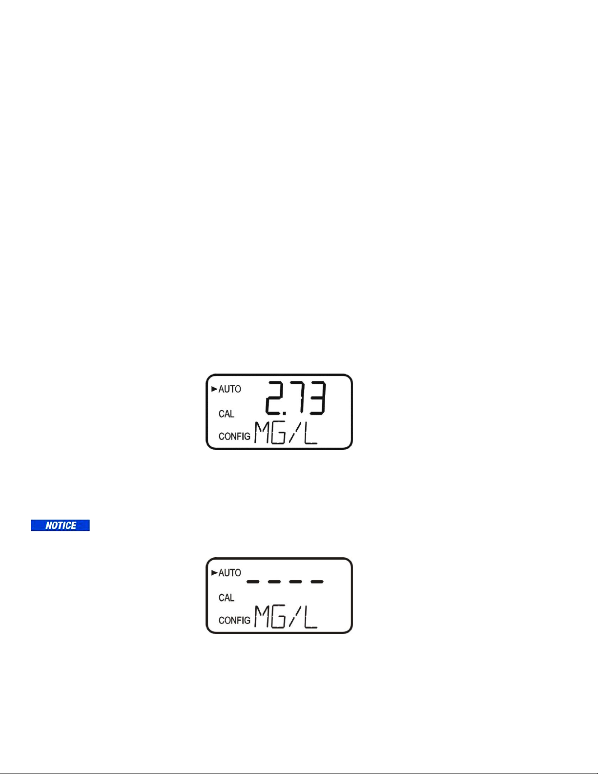
During normal operation, the instrument will have the arrow beside AUTO highlighted
with the current scale displayed on the lower row of the display and the measured reading
on the upper row of the display (see illustration below).
The screen depicted below indicates that the system has just been started or just entered
AUTO mode from Service mode and no readings have been taken yet.
Please note that calibration will not be allowed until a reading is posted.
CLX (4/18) Page 11
REV 6.0
Page 18
5.2 Security Access Feature
The instrument is equipped with a security access code feature that can be activated in the
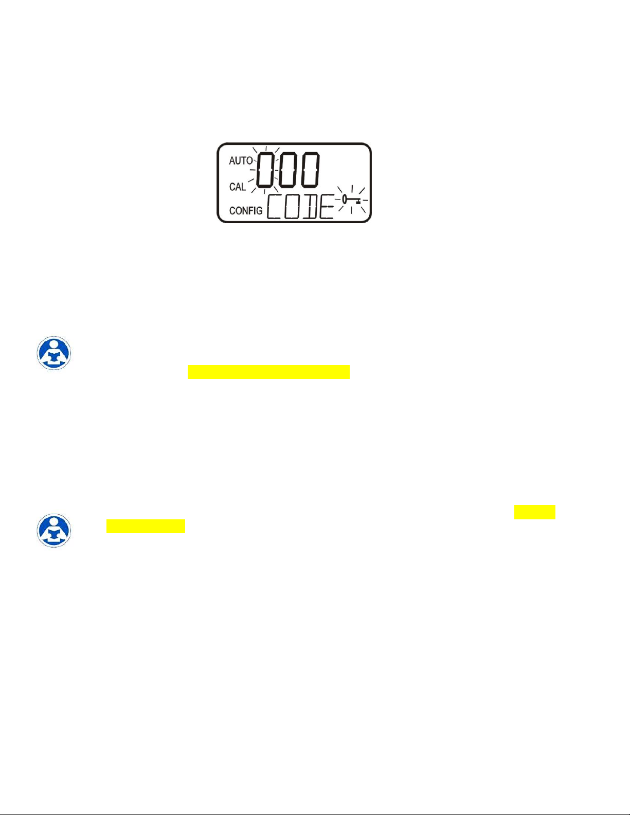
configuration mode. If the security feature is enabled, the screen shown in the illustration
below will appear when the MODE/EXIT button is pressed.
The security code (333) must be entered to gain access to CAL or CONFIG menus.
Notice that the first number in the code is flashing. The flashing indicates that this is the
number to be changed. Use the or arrows to select the first of the three numbers in
the code and then press the button to accept the first number of the code. Now enter the
second number in the code. Proceed as with the first number followed by . Then repeat
the process for the third number in the access code, and finish with the button.
If the valid access code has been selected, the instrument will be directed to the calibration
mode. If the wrong access code is selected, the instrument will return to the AUTO mode.
Refer to section 7.5 Enabling the Security Access for more information.
5.3 The White LED
A white LED is used to illuminate the measurement cuvette for easy viewing of the
instrument operations. During the Zeroing portion of the cycle and the Measurement
portion of the cycle, when the green LED is active, the white LED is turned off to lower
interference. This normal operation for the instrument and does not represent an error or
problem.
The white LED is also used to draw attention to a problem as described in section 9.0 CLX
Fault Detection. In these instances the white LED blinks at a constant rate dependant on
the severity of the problem, but is still turned off as described above. Please note that any
fault is always posted to message queue on the lower portion of the LCD.
CLX (4/18) Page 12
REV 6.0
Page 19
6.0 Instrument Calibration
The instrument was tested prior to leaving the factory. The instrument operates from a
pre-determined calibration curve for high accuracy of residual oxidant concentration. It is
not necessary to recalibrate to maintain accuracy specifications.
If re-calibration is required by a regulatory authority, this can easily be performed if
required. The method is by comparison against another instrument, such as a laboratory or
hand held photometer (such as HF scientific’s Chlorine Pocket Photometer).
There are two points of calibration. The slope or gain and the zero (offset). To perform the
zero calibration, the instrument must be plumbed to a sample of known chlorine free
water, such as de-ionized water for a zero adjustment.
6.1 Slope (gain) Calibration Procedure
It is important that the chlorine level be quite stable to use this method. The comparison
will be made against a trusted measurement such as a chlorine photometer,
spectrophotometer, or an amperometric titration.
1. Obtain a grab sample of the flow prior entering the instrument.
2. Measure the value of the sample with one of the methods shown above.
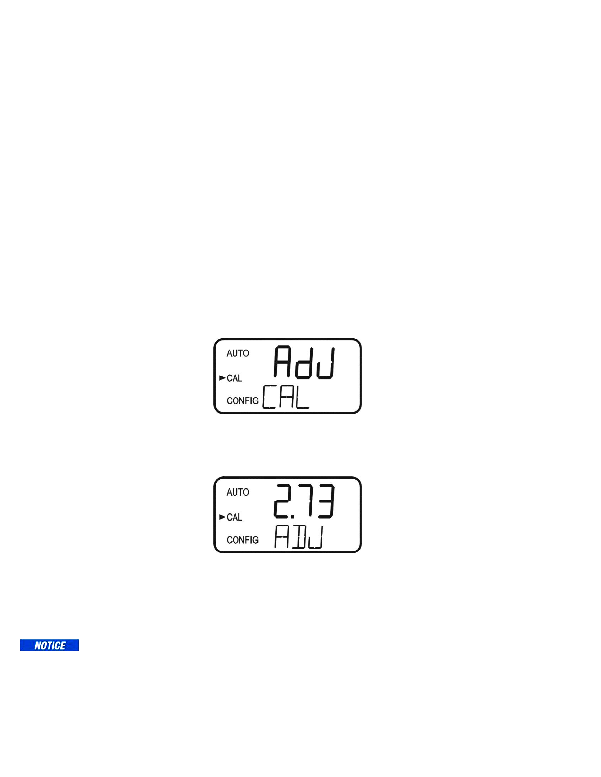
3. On the CLX, press the MODE/EXIT button once. The screen is shown below.
4. Press to enter the calibration adjustment.
5. The screen will show the current reading on the CLX. Using the & buttons
adjust the reading to agree with the laboratory method or portable photometer.
6. Press to accept the calibration adjustment and return to AUTO measurement
mode.
There is a limit to the size of the change that can be made to a current reading. The
upper limit is the current reading times 1.5. The lower limit is the current reading
divided by 1.5.
Ensure a reading is posted to the display before calibrating to avoid a nOnE error.
CLX (4/18) Page 13
REV 6.0
Page 20
6.2 Zero (offset) Calibration Procedure
Generally this calibration is only required if readings are expected to be below 1 mg/L or
if it is required by a regulatory authority. To perform this calibration, the water supply to
the CLX must be changed to chlorine free water such as de-ionized water. This chlorine
free water must be run through the instrument for at least 5 minutes prior to using the
following procedure.
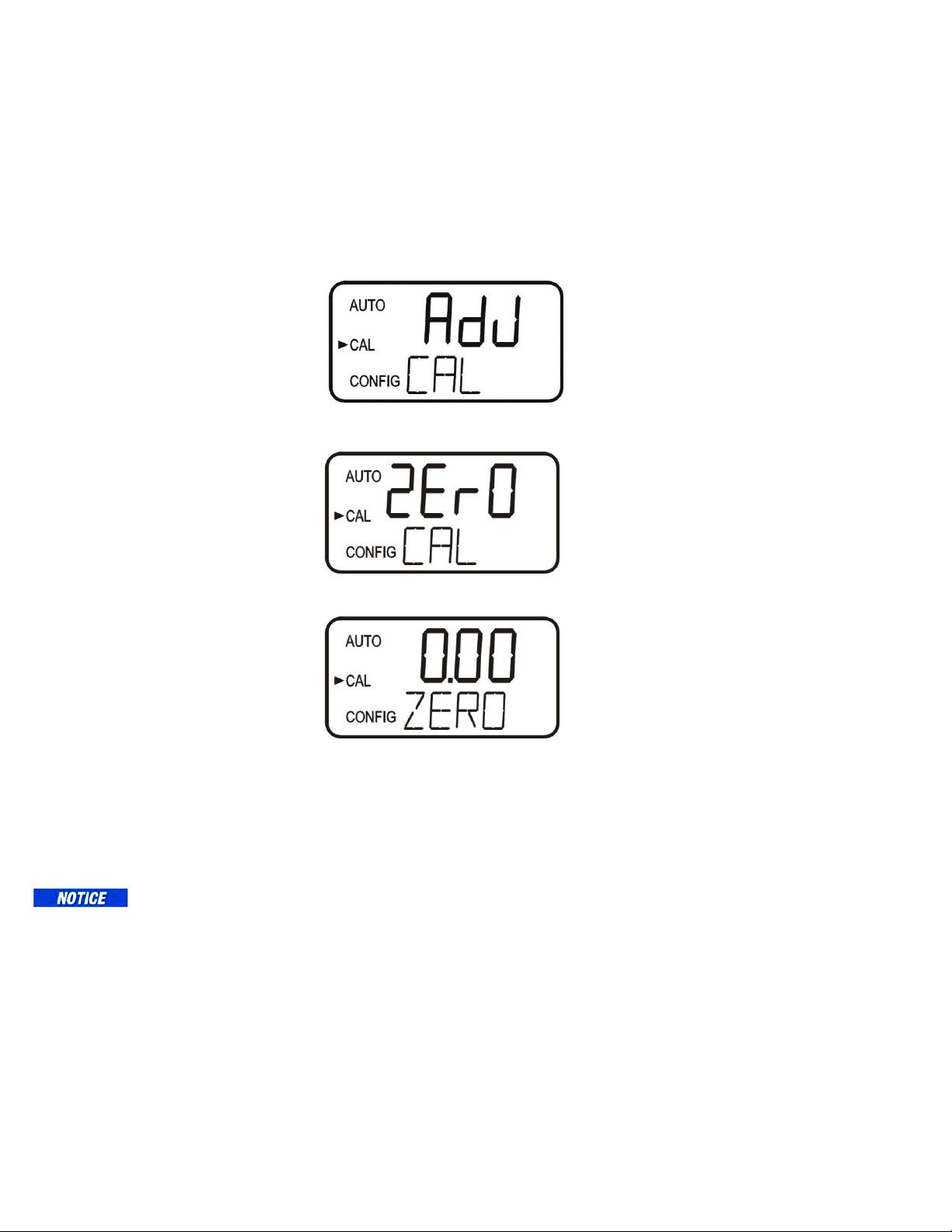
1. On the CLX, press the MODE/EXIT button once. The screen is shown below.
2. Press either the or buttons to get the following screen.
3. Press to enter the zero calibration screen.
4. The screen will show the current reading on the CLX. Since there is no
chlorine, the only reading may be a slight offset due to the absorbance of the
reagents. There should be no pink color developed.
5. Press to perform a Zero calibration. When the calibration has completed the
instrument will return to AUTO measurement mode automatically.
There is a limit of ±0.20 mg/L total adjustment available. A ZERO Cal. greater than
this will cause a CAL warning and no calibration will have occurred. Enter
SERVICE mode to clear this error.
6.3 Restore Factory Settings
If the CLX displays a CAL error or the calibration was incorrectly performed, it may be
desired to restore the factory calibration. All factory defaults including factory
configurations can be reset by holding down the button and then pressing and releasing
the button then releasing the button.
CLX (4/18) Page 14
REV 6.0
Page 21
7.0 Instrument Configuration (CONFIG mode)
The instrument has been designed to provide the ability to customize the instrument
according to needs at any time during normal operation. This mode has been split into
sub-menus to facilitate instrument configuration. This section describes how to use each
of the sub-menus to configure the instrument. While in the configuration mode, the
instrument has a time-out feature that automatically returns the system operation to the
AUTO mode after a fifteen (15) minute period of no button pushes.
Enter the CONFIG mode of the instrument by pressing the MODE/EXIT button until the
arrow beside CONFIG is illuminated, then press the button to scroll through the sub-
menus.
To exit the CONFIG mode, press the MODE/EXIT button any changes that were
made will be saved.
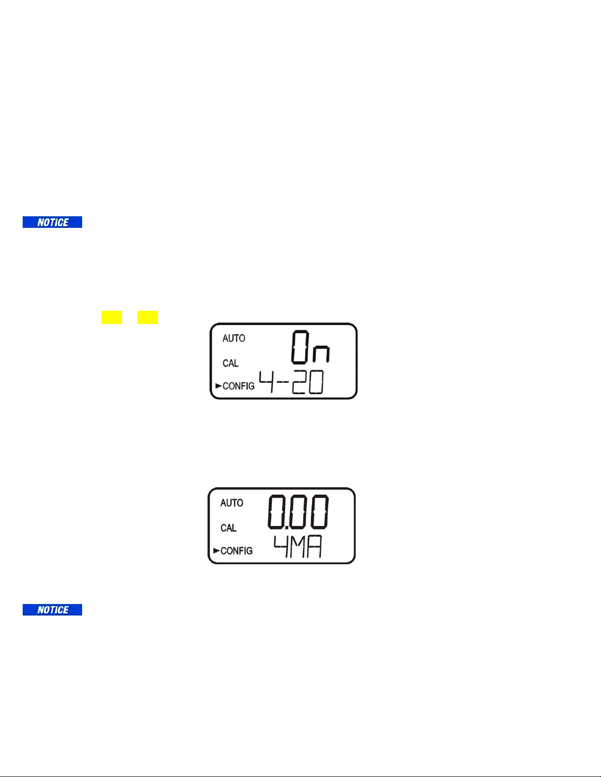
7.1 Setting the 4-20 mA Output
The first configuration selection is 4-20 for the 4-20 mA output. Select the either On or
OFF using the and buttons. Once the desired output has been set, press the
button to accept it. The next prompts will depend on the output selected. Also see sections
7.13 & 7.14.
If the 4-20 mA output was turned On, prompts to set the 4mA (4MA) and 20mA (20MA)
chlorine limits will be displayed. There will also be a menu to adjust the error level
(ERLV). The first prompt will be the chlorine limit assigned to the 4 mA output level:
Select the chlorine level to assign to the 4MA using the and buttons.
Once the desired level has been set, press the button to accept it.
The 4MA can be set higher than 20MA level to invert the output current if required.
This may be required to control a dosing pump.
CLX (4/18) Page 15
REV 6.0
Page 22
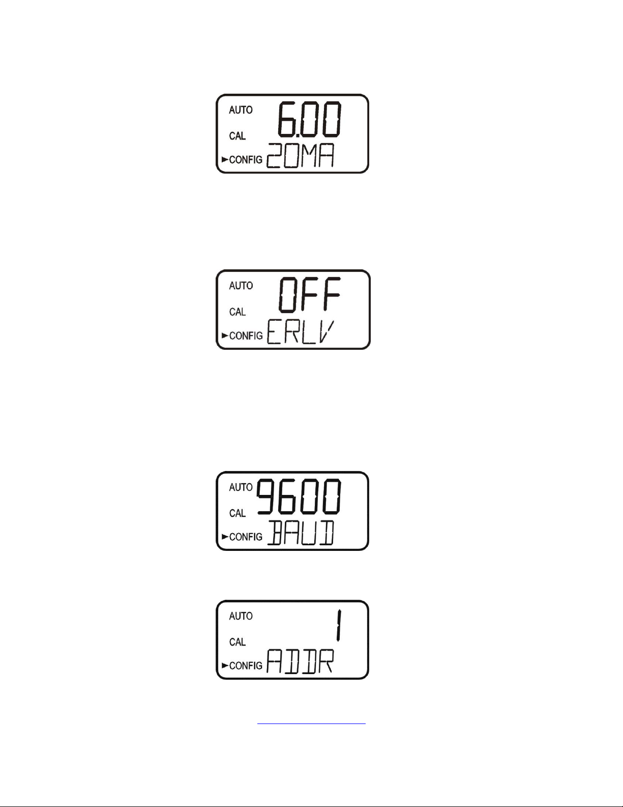
The next prompt will be the chlorine level assigned to the 20MA. Select the chlorine level
using the and buttons. Once the desired level has been set, press the button to
accept it.
7.2 Configuring the Error Level
In case of an error in the CLX, the 4-20 mA reading can be used to indicate a problem by
sending the current to either 4.00 mA, 2.00 mA or 0 mA. The factory default setting is
OFF. Select the desired ERLV by using the and buttons then press the button to
accept the desired error response.
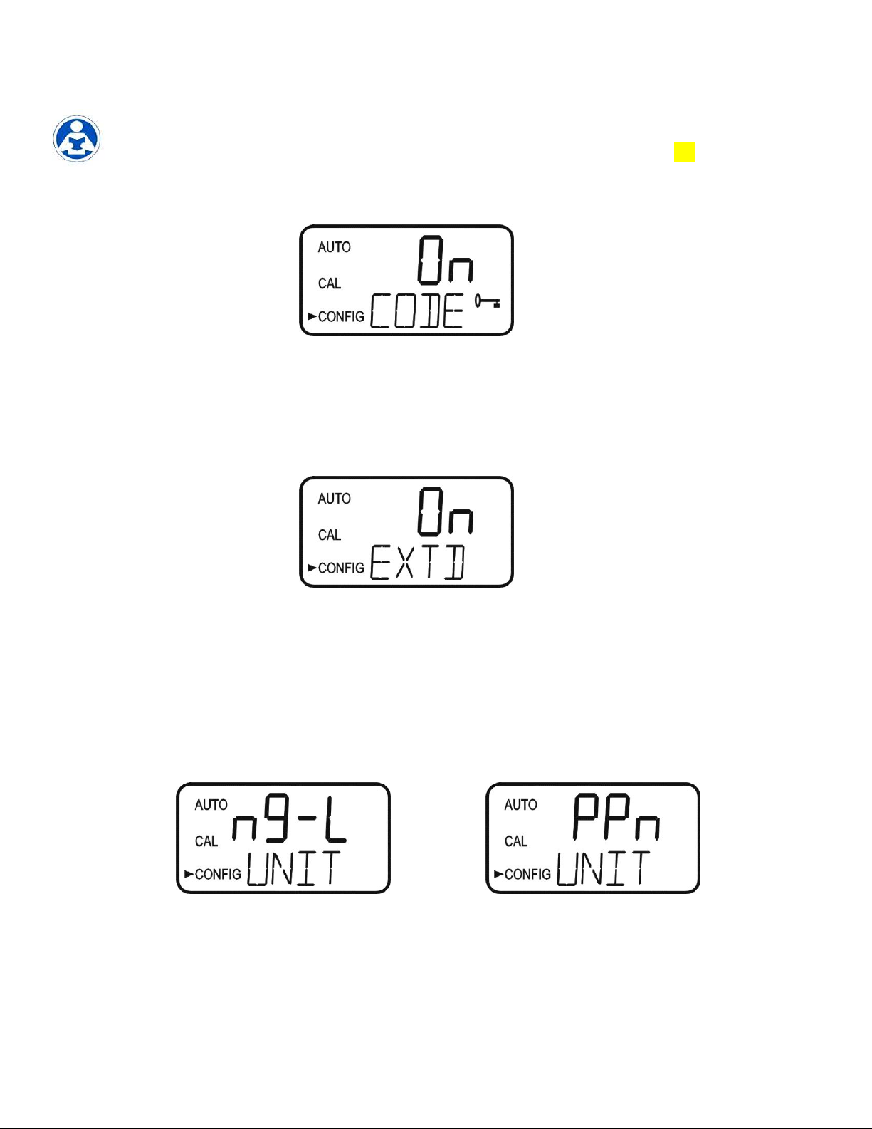
7.3 Configuring the RS–485 Port
The instrument is equipped with an RS 485 port which operates in Simple bus, a
proprietary communication (for HF Online) or Modbus. Prompts will appear for setting
the baud rate, the address and the Modbus transmission mode (RTU or ASCII).
Select the correct baud rate (1200, 2400, 4800, 9600, or 19200) for operation of the I/O
port by pressing the or buttons to change the displayed baud rate.
Press the button to continue on and select the desired instrument address using the or
buttons. Once the selection is made, press the button.
To use the Modbus mode, select ASCII or RTU. Refer to the Modbus Manual available
from HF scientific or online at www.hfscientific.com.
CLX (4/18) Page 16
REV 6.0
Page 23

7.4 Configuring the Alarms
Two relays are provided that are designed to operate as two independent programmable
alarms or as a system problem alarm. Please note that changes to alarms will not be
recognized until the start of the next cycle. Two settings must be selected to fully program
each alarm:
1. The alarm function (HI, LO, OFF or Error)
2. The alarm set point (level at which the alarm activates)
These items are described below:
Alarm Function: The alarms can either be turned OFF or selected to operate in one of
three different manners:
1. HI alarm: the relay changes state when the measured chlorine level is higher than the
programmed alarm level (set point).
2. LO alarm: the relay changes state when the measured chlorine level is lower than the
programmed alarm level (set point).
3. Error alarm: If there is a system fault or problem the alarm will change states.
Alarm Set Point: The level at which an alarm activates is called the alarm set point. On
the instrument, the alarm set point is designated as “S/P”. The set point is adjustable to
any valid chlorine level over the range of the instrument in steps of 0.01 mg/L. This
setting is not available if the Error function is chosen
7.4.1 Alarm 1
Alarm 1 Function: The ALM1 is displayed and the display indicates the current
function of alarm 1 (HI, LO, OFF, or Error). Use the or buttons to cycle
through and select the desired function. Press the button to accept the selection.
If the alarm was turned OFF, a prompt will appear to set up alarm 2, see section
7.4.2).
Alarm 1 Set Point: This prompt is used to select the set point for this alarm; this
is indicated by “S/P” shown on the lower row of the display. Select the desired
alarm level by using the and buttons. Once the desired set point has been
set, press the button to accept it.
7.4.2 Alarm 2
Repeat the procedure listed in section 7.4.1 to set up the parameters for alarm 2. If
a selection was made to turn the alarm OFF, the next selection for the speed of
response RESP is shown.
Due to the cyclic nature of the CLX, relay chatter is not an issue. There is no need for
alarm delays or hysteresis.
CLX (4/18) Page 17
REV 6.0
Page 24
7.5 Enabling the Security Access
The instrument is equipped with a security access. If this option is turned on, the user is
required to input the access code into the instrument to get to any mode other than AUTO.
The only code is 333. This code may not be changed. See section 5.2 for more
information on this security feature. The security key icon will be visible and flashing on
the display whenever the access option is selected using the or buttons. (On or
OFF).
7.6 Extended Settings
The last settings are grouped together to prevent them from being adjusted by accident. To
gain access to the extended settings, select On using the or buttons and press the
button.
If extended settings are set to OFF, pressing the button will save all settings and the
CLX will automatically return to the normal AUTO mode of the instrument.
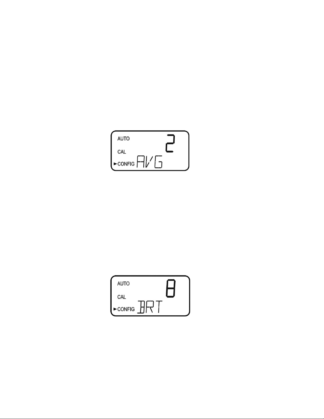
7.7 Units of Measurement
The unit of measure can be set to either mg/L (milligrams per liter) or PPM (parts per
million). The factory setting is mg/L. Select the desired UNIT using the and buttons
and press the button to accept it.
mg/L screen PPM screen
CLX (4/18) Page 18
REV 6.0
Page 25
7.8 Averaging and Filtering
The CLX can display and output averaged readings to help smooth out the response and
eliminate large reading variation in rapidly changing processes. There are 5 settings for
the averaging feature:
1 = No averaging, each reading is in “real time”.
2 = The current reading and previous reading are averaged.
3 = The current reading and previous 2 readings are averaged.
4 = The current reading and previous 3 readings are averaged.
5 = The current reading and previous 4 readings are averaged.
The factory setting is averaging of 2. Select the desired AVG using the and buttons
and press the button to accept it.
In addition to averaging, the CLX has a software filter that limits the change between
consecutive readings to 20%. For example, the reading following a reading of 1.00 ppm
could not be displayed as higher than 1.20 ppm or lower than 0.80 ppm. This filter also
helps smooth out large changes and eliminate reading spikes. After 3 consecutive
readings, it is assumed that the large change in the readings is "real", and the filter will be
disabled. For example, the change between reading 1 & 2, and readings 2 & 3 will be
limited to 20%, but the change between readings 3 & 4 will not be limited.
Note: This software filter is completely disabled when the averaging (AVG) is set to 1.
7.9 LCD Backlight Brightness
The LCD backlight brightness may need to be adjusted. This is of particular interest if
multiple instruments are located in the same area and it is desired for the entire group to
have the same appearance. Ten levels are available. The factory setting brightness is 8.
Change the brightness by pressing the or button. When the desired brightness has
been selected, press the button.
CLX (4/18) Page 19
REV 6.0
Page 26

7.10 RS-485 Parameters
These menus will only appear if the RS-485 is enabled (see 7.3). The factory setting is 8
Bit, no (nOnE) Parity, 1 Stop Bit.
Make selections using the and buttons then press the button to move to the next
menu.
7.11 Cycle Time
The cycle time can be changed using this menu. Please note that changing this menu
will directly affect the volume of reagent that will be consumed. The default is set to
150 seconds (2 ½ minutes). Using this setting the reagents will last 30 days.
Make selections using the and buttons then press the button. Allowable setting is
from 110 to 600 seconds (10 minutes).
Reagents have a 30 day life after being mixed regardless of the cycle time setting.
7.12 Water Conservation
To conserve water, the flush time can be adjusted use as little water as possible.
The instrument requires 110 seconds to complete its normal operations, when the WCON
is turned On, at the factory cycle time the instrument sits idle for about 40 seconds. This
results in about a 25% water savings. The actual amount of water conservation is
dependent on the incoming water pressure and the cycle time setting.
The use of this option may result in some slight loss of accuracy. The factory setting for
this option is OFF.
Make selections using the and buttons then press the button to exit to AUTO
mode and save all configuration settings. If the 4-20 mA in section 7.1 is turned ON, there
are two additional menus that will appear before returning to AUTO mode.
CLX (4/18) Page 20
REV 6.0
Page 27
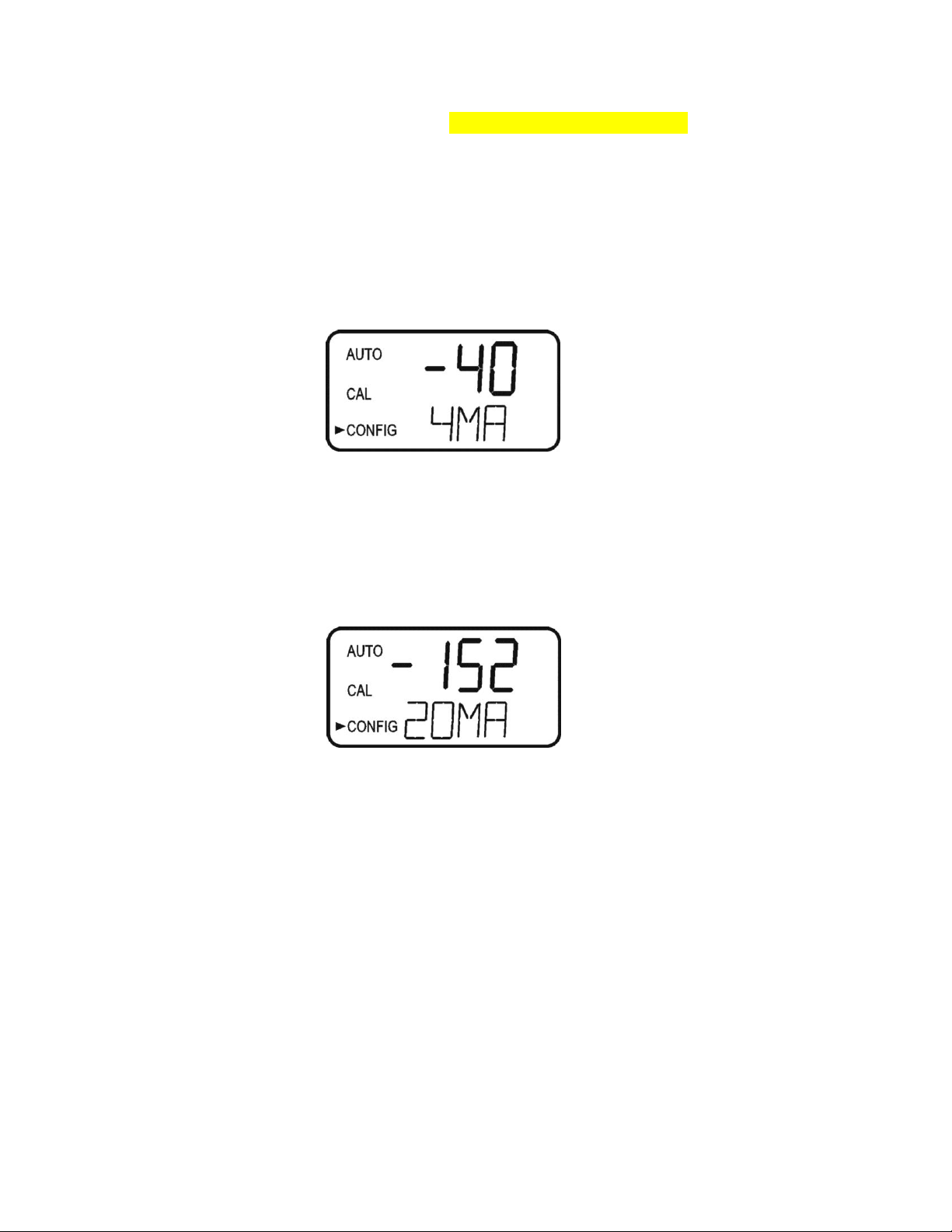
7.13 4mA Adjustment
If the 4-20 mA setting is turned ON (7.1 Setting the 4-20 mA Output), the following two
menus will appear. The first menu outputs a constant 4 mA while allowing for a small
amount of adjustment. The adjustment can be made using the and buttons. This
adjustment will allow the operator to make the CLX agree with a PLC or SCADA system.
The adjustment limits are ± 200 counts or about ± 0.2 mA.
This setting will be slightly different on each instrument as each CLX will be factory set
to 4.00mA. Press the button when adjustments are complete to save this setting and
move on to the 20mA adjustment.
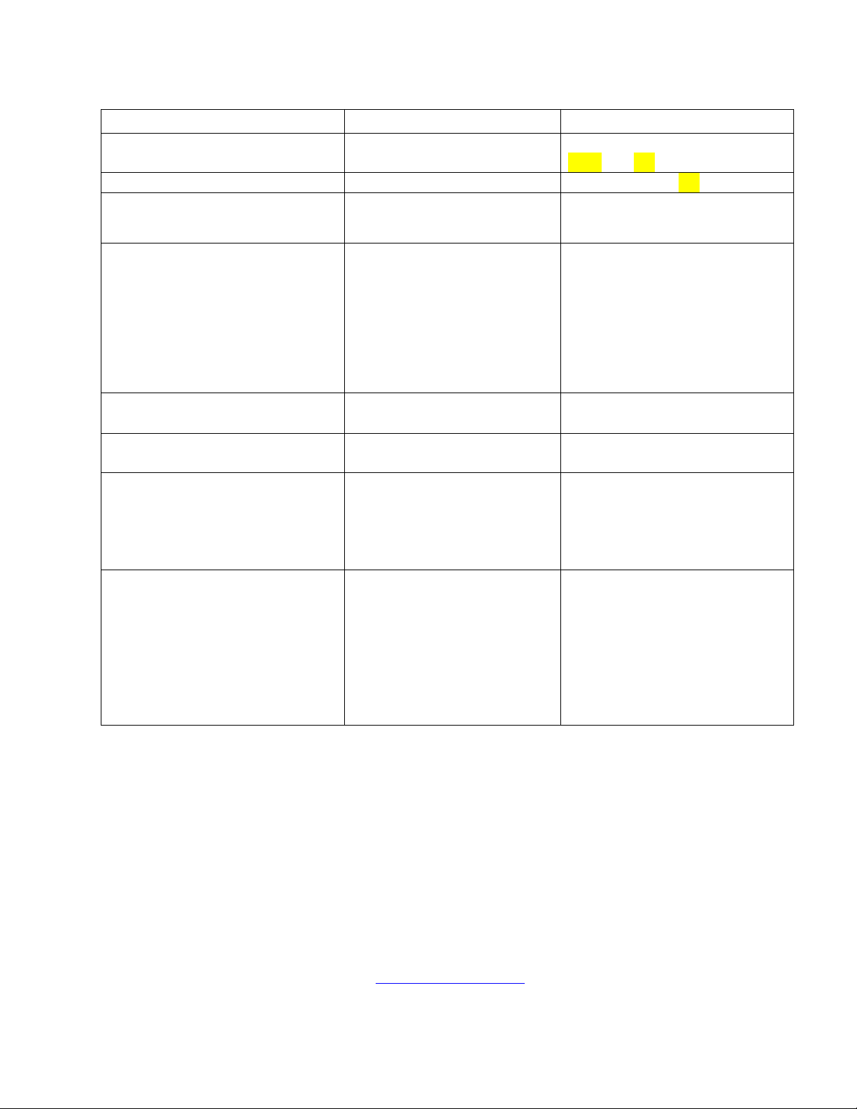
7.14 20mA Adjustment
This menu operates similar to the previous menu. This menu outputs a constant 20 mA
while allowing for a small amount of adjustment. The adjustment can be made using the
and buttons. The adjustment limits are ± 1000 counts or about ± 1 mA.
This setting will be slightly different on each instrument as each CLX will be factory set
to 20.00mA.
When complete with the 20mA adjustment, press the button to exit to AUTO mode and save all
configuration settings.
CLX (4/18) Page 21
REV 6.0
Page 28

8.0 Additional Features and Options
8.1 Backlit LCD
The backlit LCD allows for easier readability of the LCD display in low light or no light
conditions. The backlight is intended for continuous operation. The brightness is
adjustable from a menu in the CONFIG mode.
8.2 RS-485 Outputs
The CLX has the capability to operate in three different RS-485 modes. Included is a
mode for interfacing into the HF Online software package (section 8.2.1 below), a simple
communication mode and Modbus communications. All modes will automatically
configure and do not require any changes or selections
8.2.1 HF Online (HF catalog # 19783)
The CLX can operate as a small SCADA system with an optional PC software
package, called HF ONLINE. This system allows for an interface with a
combination of Micro TOL’s or CLX’s, totaling up to 255 units, for the purpose of
data logging. This system will interface directly with common database and
spreadsheet software.
8.2.2 Simple Communication
The CLX can provide basic communications over simple programs such as the
Hilgraeve HyperTerminal that is included with most Microsoft Windows
packages. The user could also use Visual Basic or other programs. The factory
setting communication parameters are 8 bits, no parity and 1 stop bit. These can be
changed in the Extended CONFIG menus 7.10 RS-485 Parameters.
The master computer will send out:
Byte #1 the attention character “:” in ASCII or 3A Hex
Byte #2 the address of the CLX being queried
Byte #3 & 4 CR LF or 0D 0A in hex
The CLX will respond with:
The same attention character “:” in ASCII or 3A Hex
The address of the CLX
The Reading
The Unit (mg/L)
A sample communication would look like this:
(Master computer requesting a report from address #1) :1 CRLF
(CLX set to address #1 Response) :001 0.0249mg/L
CLX (4/18) Page 22
REV 6.0
Page 29

8.2.3 Modbus Communication
Modbus protocol communication manual is available HF #24569. This manual is
available free online at www.hfscientific.com.
8.3 Remote Panel Meter (Catalog # 19609)
The remote panel meter allows for remote indication of the mg/L reading using the 4-20
mA loop of the CLX. No external power is required, as the meter is run off of the 4-20
mA source of the CLX.
8.4 Desiccant Cartridge Option (Catalog #09944)
An optional desiccant cartridge kit can be purchased for use in applications where
condensation on the glass cuvette may compromise accuracy. The desiccant changes color
from blue to tan when expended. Instructions for replacement are included with the kit.
CLX (4/18) Page 23
REV 6.0
Page 30

Message
Description of Fault
Corrective Action
MA
4-20 mA enabled & loop open
Check 4-20 mA wiring or turn off 4-
20mA if not used
CAL
Calibration invalid –not accepted
Recalibrate if needed
WATR
No water flowing
Check water flow
FAST
Intake water flow too fast
Set flow rate (see section 9.2)
SLOW
Sample cuvette filling too slowly
Set flow rate (see section 9.2)
PURG
Sample cuvette has slow purge
Check drain lines
NPRG
Sample cuvette not purging
Check drain lines
ISOL
Problem with intake solenoid
Check wiring, check for clogged solenoid
PSOL
Problem with purge solenoid
Check wiring, check for clogged solenoid
GLAS
Dirty cuvette
Replace or clean cuvette
WCAL
Water Level Calibration Invalid
Clear fault (see section 9.3)
9.0 Troubleshooting
9.1 CLX Fault Detection
The CLX performs continuous diagnostic monitoring. In the CLX, there are 4 severity
levels of fault detection. Level 4, 3 & 2 will allow normal operation, but warn of the
problem. Level 1 is an instrument failure and the instrument will not operate. Any faults
are displayed in a queue form in the bottom row of the LCD.
A level 4 fault is simply a screen indication that one of the alarm levels has been
activated. This fault level will not affect the 4-20 mA and will only affect the alarm
activated. The sample back light blinks at a rate of once every 4 seconds.
A level 3 fault indicates a failure or a problem that usually can be corrected by the
operator. Refer to the chart below. If any of these errors occur, the instrument will still
display readings and probably will operate correctly. These faults will self-clear when the
problem is corrected. If any of these faults occur, they may affect the 4-20mA and any
alarm dependent on fault detection setting (Error). See sections 7.2 & 7.4.1 for error
settings. The sample back light blinks at a rate of once every 2.5 seconds to indicate a
level 3 fault.
Level 3 (Self-Clearing) fault conditions
A level 2 fault indicates a severe problem that will usually require technical assistance
from HF scientific customer service (see section 9.5). The queued display will show
POST. If this fault occurs it will affect the 4-20mA and any alarm set for fault detection
(Error). The sample back light blinks at rate of once every 1 second.
CLX (4/18) Page 24
REV 6.0
Page 31

A level 1 fault is a system fault. This is NOT a problem that the operator can correct, and
the unit must be returned to the factory for service (see section 9.5). These failures consist
of failures in the CPU, A/D, EEPROM or other devices internal to the instrument. The
queued display will show FAIL, the upper display is a five digit code. If this fault occurs,
it will affect the 4-20mA and any alarm set for fault detection (Error). The instrument will
not operate with this fault. The sample back light blinks at rate of once every 0.4 seconds.
If any fault condition occurs, the message indicating the fault will be shown on the lower
row of the display.
9.2 Setting Flow Rate
The flow rate on the CLX was factory adjusted and should not need adjustment.
Installation variances may affect the flow. The optimal flow rate through the CLX may be
adjusted if needed. The flow is adjusted by removing regulator vinyl cap and turning the
adjustment screw on the pressure regulator. Refer to figure 4. To assist in this adjustment
follow the procedure shown below:
1. Press the SERVICE button.
2. Wait for the display to read HOLd, then press Mode/
Exit.
3. Display will show FLOW with the number 0. Press either the or button.
4. CLX will drain, and then pulse in water while a count is displayed on the screen.
5. The display will show one of three messages HI, LO or Good.
The flow test determines if the flow rate is suitable for proper operation. Loosen the
locking nut then adjust the pressure regulator using a coin or a large flat blade
screwdriver. Press either the or button while in the FLOW routine to display a new
flow rate. Please note that only ¼ turn incremental adjustments should be made to the
regulator on each attempt.
If the message is LO, turn the regulator control clockwise. If the message is HI, turn the
regulator counterclockwise. If the message is Good, no adjustment is required. Tighten the
locking nut after adjustment and replace the regulator vinyl cap. To return to normal
operation, press the button.
9.3 Clearing Faults
Every time SERVICE mode is exited, all faults are cleared. If the original fault or a new
fault occurs, it will be posted.
9.4 Reagent Clogs
If reagents fail to flow or Prime it may be due to a clog in either the tubing or at a check
valve. To alleviate this you may have to flush the system with Chlorine Free water,
preferably Deionized water. See section10.4 Check Valve Flushing Kit.
CLX (4/18) Page 25
REV 6.0
Page 32
Symptom
Cause
Cure
Lower display shows MA
4-20 mA loop open
Check wiring. See sections
4.3.4 and 7.2
Lower display shows FAIL
Major system fault
Refer to section 9.1
Readings are erratic
(1) Bubbles in solution
(2) Debris in flow
(1) See above
(2) Install T strainer at inlet
Readings are lower than expected
(1) Condensate or leaky
measurement cuvette
(2) Measurement cuvette
dirty
(3) Reagents bad or expired
(4) Buffer reagent not being
dispensed
(1) Install desiccant cartridge
kit
(2) Replace or clean cuvette
(3) Replace reagents
(4) Check buffer lines and
check valves.
Upper display flashes
Sample Over-Range
Check sample. Sample may be
too high to read.
Upper display shows nOnE while
attempting to calibrate
No current reading displayed
Wait for CLX to post a reading
Instrument displays WCAL in
AUTO mode
Water was not running when
power was applied.
Ensure water is turned on then
Press PRIME. System will
correct the problem by running
a WCAL in CAL mode then
change to AUTO mode.
Instrument will not prime
Check valves clogged
Check valves bad
Try using the supplied check
valve flush kit (syringe) or a
squeeze bottle filled with nonchlorinated water.
(1) Soak check valve in nonchlorinate water for 2-3 hours.
(2) Install 25017S check valve
replacement kit
9.5 Diagnostic Chart
9.6 Technical and Customer Assistance
If for any reason assistance is needed regarding this instrument please do not hesitate to
contact either the HF scientific Technical Service Department or the HF scientific
Customer Service Department:
CLX (4/18) Page 26
REV 6.0
HF scientific
3170 Old Metro Parkway
Fort Myers, Florida 33916-7597
Phone: (239) 337-2116
Fax: (239) 332-7643
Toll Free: 888-203-7248
Email: HF.Info@Wattswater.com
www.hfscientific.com
Page 33

10.0 Routine Maintenance
10.1 Normal Maintenance Schedule
The recommended schedule is shown below. It is important to replace the reagents on a
monthly basis to get reliable accurate readings from the CLX.
The CLX is shipped with one CLX Tubing/Cuvette kit, HF part # 09950. The kit consists
of the following:
Qty Part
2 Cap Assemblies
8 Pump Tubes
1 Cuvette
Two complete cap assembly sets are used in the CLX; one for the buffer and one for the
indicator.
The supplied kit is intended to last for one year. Additional kits can be ordered from your
local HF scientific distributor or representative. It is recommended to keep one kit on hand
at all times.
Generally, all pump tubes should be replaced on an annual basis. The Cap assemblies and
the cuvette should be replaced as required.
Every Month
1. The reagent required for operating this instrument must be changed on a monthly
basis (with a 2.5 minute cycle time).
2. The external strainer should be checked and cleaned if necessary
3. The glass cuvette should be inspected. Check for excessive debris on the inside
surface of the glass. It is suggested to keep a spare cuvette to replace when required.
The old cuvette may be cleaned, if possible, for future replacement.
Flushing the System
It is recommended that the tubings replacements be timed with reagent replacement. Press
the SERVICE button to stop the water flow. Remove old reagents and discard. Place the
inlet tubings in a small container of clean water. Press SERVICE to return to operation
mode, press PRIME and then to flush the system with water. Remove the inlet tubings
from the water Press PRIME and then to remove most of the water.
After a PRIME the CLX will perform a water calibration (WCAL). It will take a few
minutes to complete this procedure.
CLX (4/18) Page 27
REV 6.0
Page 34

Annual Pump Tubing Replacement
The pump tubing may need replacement more often due to the fact that they are subject to
wear from the reagent “Pump”. The check valves should not need to be replaced and
should be saved. Please note that the check valves are directional and that the “IN” side is
smaller in diameter (see drawing).
Steps:
1 Flush the system as described above to reduce personal contact with the reagents.
2 Press SERVICE to stop the flow of sample water and drain the cuvette.
3 Remove and retain the thumb screw on top of the pump; pull the pump hammer and
spring up and out of the way. There is no need to completely remove the hammer and
spring.
4 Working on one reagent side at a time. Replace the black pump tubing between optics
inlet and the check valve OUTLET. Discard the old tubing.
5 Ensure the check valve is placed into its seat in front of the pump assembly.
6 Repeat steps 4 & 5 for the other reagent.
7 Replace the hammer and spring back into place and secure with the thumb screw.
8 Check the drawing on the following page to ensure correct installation.
9 Return to operation as described.
Cap Assembly Replacement
The Cap Assembly can be changed as needed. Check the condition of cuvette and change
if it appears badly soiled or discolored. Follow the steps below:
Cuvette Replacement
To replace the cuvette, press the SERVICE key. When HOLD shows on the screen,
the system is ready.
Check the condition of cuvette and change if it appears badly soiled or discolored. Follow
the steps below:
1. Turn the knurled top on the optics system counterclockwise (as viewed for the top)
until the cuvette just “pops” out, but do not remove the top.
2. When the cuvette “pops” out, move the retaining o-ring & remove the cuvette. You
may need a stiff wire such as a bent paper clip to grasp the cuvette. Retain this cuvette
for future use if it can be cleaned.
3. Install the new or clean cuvette by pushing it firmly in place and turning the knurled
top clockwise until the cuvette is held securely.
4. Check the drawing on the following page to ensure correct installation.
5. Return to operation as described.
Return to Normal Operation
Press the SERVICE button to return sample flow to the system. Check for leaks. If a leak
occurs press SERVICE again, repair leak and try again. Once the system is operating
correctly, return or replace reagents and press PRIME and then one time to restart
reagent flow. The system will automatically return to normal operation.
Tubes may darken due to contact with the reagent. This condition does not affect the
performance of these parts.
CLX (4/18) Page 28
REV 6.0
Page 35
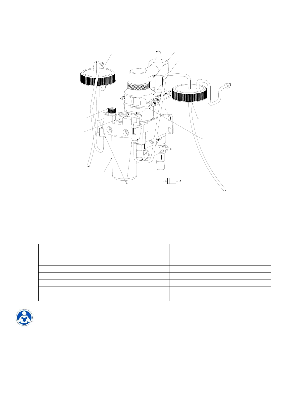
INLET
CHECK
VALVES
CAP ASSEMBLY "A"
PUMP
HAMMER
AND SPRING
THUMB
SCREW
REAGENT
PUMP
ASSY
INLET
OUTLET
FLOW
CHECK VALVE DETAIL
OPTICS SYSTEM
KNURLED TOP
CUVETTE
RETAINING
O-RING
CAP ASSEMBLY "A"
Procedure
Maintenance Period
Detail
Change Reagents
Once per month
See replacement parts list
Check Cuvette
Once per month
Clean or replace if needed
Check T-Strainer Screen
Once per month
Clean or replace if needed Cat# 28625S
Replace Pump Tubes
Once every six months
Included with Tubing/ Cuvette Kit
Replace Cap Assemblies
Once per year
Tubing/Cuvette Kit Cat # 09950
Replace Check Valves
Once per year
Check Valve Kit Cat # 25017S
Clean T-Strainer Screen
Once per year
Clean or replace if needed Cat #28625S
Figure 6: Reagent Tubing Installation
10.2 Preventative Maintenance Schedule
To ensure the instrument will operate reliably, some sites may wish to implement
preventative maintenance. The proposed schedule is shown below:
CLX (4/18) Page 29
REV 6.0
Follow the enclosed procedures with any of the kits or parts mentioned above.
Page 36

10.3 Replacing or Installing the Reagents
Reagent kits are available from HF scientific for Free Chlorine and for Total Chlorine
Refer to section 11.0 Replacement Parts and Accessories for the appropriate Catalog
numbers. There are two reagents required, and supplied in each kit; the buffer and the
indicator.
The buffer and indicator reagents are provided as dry reagents and require the addition of
deionized water. You will need to have at least 1 liter of deionized water on hand prior to
preparing the solutions. Allow about ½ hour time to prepare the reagents.
Use caution while preparing. The indicator reagent is corrosive and can stain
clothing. The use of protective gloves, clothing and eye protection is recommended.
When commissioning the CLX it is recommended to follow the procedure in section
10.4. This procedure should only need to be done once when first put into service.
Buffer Reagent Preparation
Add about 400 ml of deionized water into the buffer bottle. Cap tightly and shake
vigorously until the powder is fully dissolved. When fully dissolved add enough deionized
water to bring the volume in the bottle up to the fill line.
Indicator Reagent Preparation
Add about 400 ml of deionized water into the indicator bottle. Cap tightly and shake
vigorously until the powder is dissolved. Remove the cap and add the contents of the DPD
powder bottle (small brown bottle). Cap and shake to fully dissolve the powder. When
fully dissolved add enough deionized water to bring the volume in the bottle up to the fill
line.
Once mixed the reagents have an expected life of 30 days. Write the mixing date on
the reagent bottle labels in the area provided. Dispose of expired reagents correctly.
To replace the reagents, press the SERVICE button; this will empty the cuvette and stop
any flow of water. Remove the cap on both bottles replace with the cap supplied with the
CLX. Be sure to replace the reagents in the correct location as labeled on the inside of the
CLX. The buffer is installed on the left and the indicator is installed on the right side. The
suction tube for both reagents will reach the bottom of the bottles.
To complete the replacement procedure, press the PRIME button and then the button.
This will draw enough of each reagent to completely prime the tubes and replace any old
solution. The system will automatically return to normal operation after it has primed.
Use caution when changing the reagents as they are corrosive. These reagents will
stain clothing and anything they contact. After changing the reagents, operators
should wash their hands.
CLX (4/18) Page 30
REV 6.0
Page 37
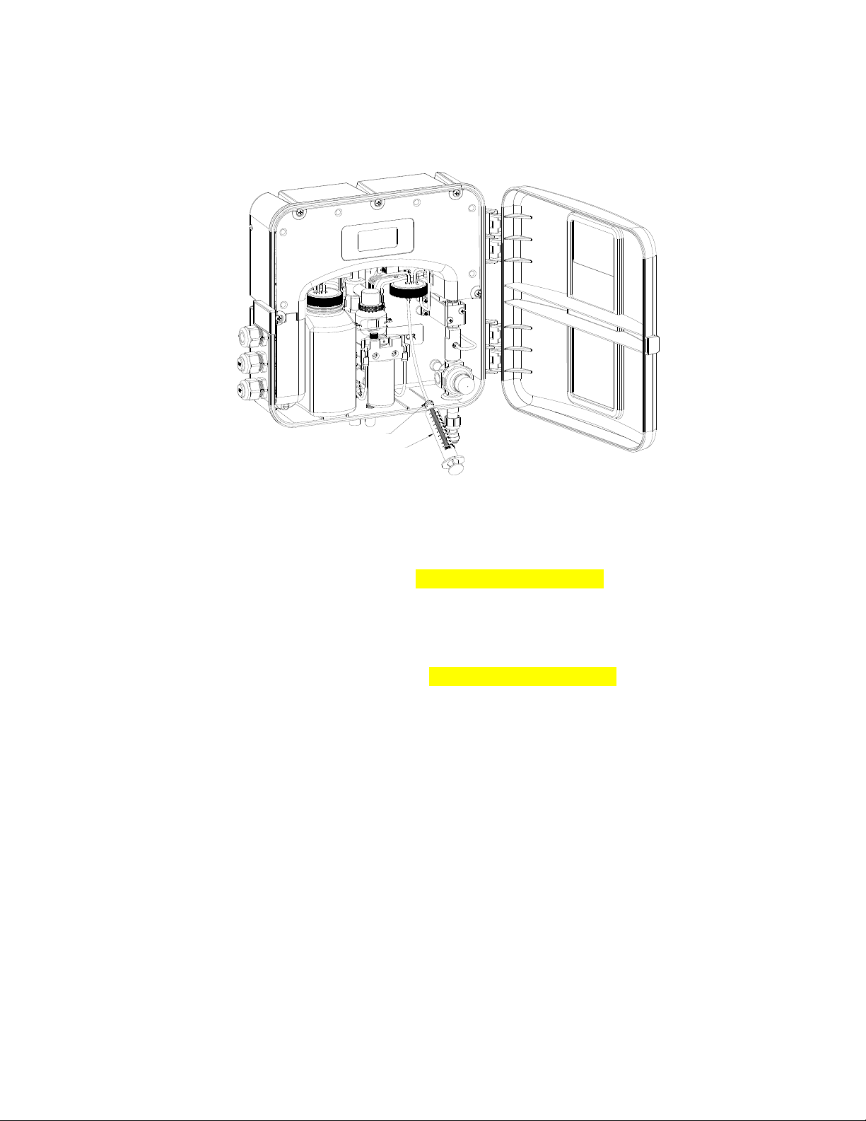
10cc Syringe
Leur-Lok Barbed Adapter
10.4 Check Valve Flushing Kit
Sometimes upon initial commissioning, the check valves stick and require manual
priming. This should not be needed after commissioning. Be careful when using this kit to
use only chlorine free water. Complete instructions are included in the kit.
Figure 7: Check Valve Flushing Kit
10.5 Instrument Storage
If the CLX is relocated or will be inactive for more than 48 hours, remove the reagents.
Flush the reagent system as describe in 10.1 Maintenance Schedule. Place the instrument
in Service mode to drain the system then remove power by disconnecting the mains power
plug. It is usually a good idea to disconnect or shut off the source water.
10.6 Cleaning the CLX
Flush the system as mentioned in section 10.1 Maintenance Schedule. When the flushing
is finished, press the SERVICE button wait until the display reads HOLd.
As a mater of safety, always disconnect any power source to the CLX prior to attempting
any cleaning. It is recommended that the source water is also shut off.
Isopropyl alcohol (rubbing alcohol) on a soft cotton cloth works very well in removing
reagent stains from plastic parts, the key pad and the display. Use care when cleaning
around electrical components. Do not use any harsh cleaning agents as these may cause
damage to the instrument components.
Ensure that the system is dry prior to applying power.
CLX (4/18) Page 31
REV 6.0
Page 38

Accessory
Catalog
Number
Photo
J.A.W. Reagent Kit – Free Chlorine 30 day supply
09951
J.A.W. Reagent Kit – Total Chlorine 30 day supply
09952
J.A.W. Reagent Kit – Free Chlorine 60 day supply
09953
Two kits of 09951
J.A.W. Reagent Kit – Total Chlorine 60 day supply
09954
Two kits of 09952
J.A.W. Reagent Kit – Free Chlorine 12 month supply
09955
12 kits of 09951
J.A.W. Reagent Kit – Total Chlorine 12 month supply
09956
12 kits of 09952
Operating Manual CLX
24420
N/A
Tubing/Cuvette Kit
09950
Replacement T-Strainer Screen
28625
11.0 Accessories and Replacement Parts List
The items shown below are recommended accessories and replacement parts.
CLX (4/18) Page 32
REV 6.0
Page 39
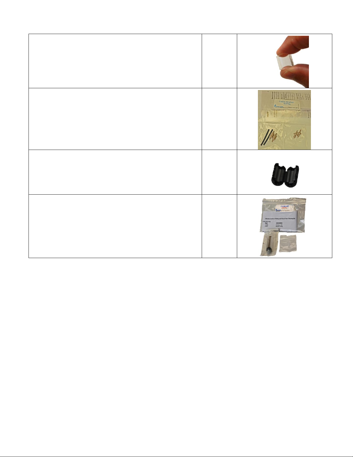
Replacement Cuvette
25018S
Check Valve Set
25017S
Ferrite for 4-20mA or RS-485
24560
Check Valve Flushing Kit
25096
To order any accessory or replacement part, please contact the HF scientific Customer
Service Department. If for any reason technical assistance is needed regarding this
instrument, please do not hesitate to contact the HF scientific Technical Services
Department.
CLX (4/18) Page 33
REV 6.0
HF scientific
3170 Old Metro Parkway
Fort Myers, Florida 33916-7597
Phone: (239) 337-2116
Fax: (239) 332-7643
Toll Free: 888-203-7248
Email: HF.Info@Wattswater.com
www.hfscientific.com
Page 40

12.0 Warranty
HF scientific inc., as vendor, warrants to the original purchaser of this instrument that it
will be free of defects in material and workmanship, in normal use and service, for a
period of two years from date of manufacture. This warranty includes only instruments
coved in this manual manufactured after January 1, 2012. HF scientific inc.’s obligation
under this warranty is limited to replacing, at its factory, the instrument or any part
thereof. Parts, which by their nature are normally required to be replaced periodically,
consistent with normal maintenance, specifically reagent, desiccant, sensors, electrodes
and fuses are excluded. Also excluded are accessories and supply type items.
Original purchaser is responsible for return of the instruments, or parts thereof, to HF
scientific’ inc.’s factory. This includes all freight charges incurred in shipping to and from
HF scientific inc.’s factory.
HF scientific inc .is not responsible for damage to the instrument, or parts thereof,
resulting from misuse, environmental corrosion, negligence or accident, or defects
resulting from repairs, alterations or installation made by any person or company not
authorized by HF scientific inc.
HF scientific inc. assumes no liability for consequential damage of any kind, and the
original purchaser, by placement of any order for the instrument, or parts thereof, shall be
deemed liable for any and all damages incurred by the use or misuse of the instruments, or
parts thereof, by the purchaser, its employees, or others, following receipt thereof.
Carefully inspect this product for shipping damage, if damaged, immediately notify the
shipping company and arrange an on-site inspection. HF scientific inc cannot be
responsible for damage in shipment and cannot assist with claims without an on-site
inspection of the damage.
This warranty is given expressly and in lieu of all other warranties, expressed or implied.
Purchaser agrees that there is no warranty on merchantability and that there are no other
warranties, expressed or implied. No agent is authorized to assume for HF scientific inc.,
any liability except as set forth above.
HF scientific, inc.
3170 Old Metro Parkway
Fort Myers, Florida 33916-7597
Phone: (239) 337-2116
Fax: (239) 332-7643
Toll free: 888-203-7248
Email: HF.Info@Wattswater.com
Website: www.hfscientific.com
CLX (4/18) Page 34
REV 6.0
 Loading...