

Page 1
OWNER’S MANUAL
AccUView Wastewater
UV Transmission Monitor
3170 Metro Parkway
Ft. Myers, FL 33916
Phone: 239-337-2116
Fax: 239-332-7643
E-Mail: HFinfo@Watts.com
Catalog No.24743 (1/09) Website: www.hfscientific.com
Rev. 2.9
HF scientific
Page 2

Page 3

DECLARATION OF CONFORMITY
Application of Council Directive
Standards to Which Conformity is Declared:
Product Safety - Tested and passed CE EN61010-1: 1990 + A1: 1992 (73/32 EEC)
- Tested and passed ETL (tested to UL 61010B-1)1st Edition, Dated
January 24, 2003
- Tested and passed ETLc (tested to CSA C22.2#1010.1-92)
Immunity – Tested and passed EN61326: 1997+A1: 1998
Including:
IEC61000-4-2
IEC 61000-4-3
IEC 61000-4-4
IEC 61000-4-5
IEC 61000-4-6
IEC 61000-4-8
IEC 61000-4-11
Emissions - Tested and passed EN61326-1: 2006
Manufacturer’s Name: HF scientific, inc.
Manufacturer’s Address: 3170 Metro Parkway, Fort Myers, Florida 33916-7597
Importer’s Name:
Importer’s Address:
Type of Equipment: Process Monitor
Model No: AccUView Wastewater
I, the undersigned, hereby declare that the equipment specified above conforms to the
above Directive and Standard
Place: Fort Myers, Florida USA
(Signature)
Rowan T. Connelly, General Manager
Page 4

Page 5

Table of Contents
Section Page
Specifications .................................................................................................... 1
1.0 Overview & Orientation.................................................................................... 2
1.1 Unpacking and Inspection of the Instrument and Accessories ............. 2
1.2 The Display ..........................................................................................3
1.3 The Touch Pad ...................................................................................... 3
1.4 Vapor Purge........................................................................................... 4
1.5 The AccUView Wastewater Panel........................................................ 4
2.0 Safety................................................................................................................. 5
2.1 Symbols used on Instrument & In Manual............................................ 5
3.0 Installation and Commissioning ....................................................................... 6
3.1 Mounting and Site Selection .................................................................6
3.2 Plumbing ............................................................................................. 7
3.3 Electrical Connections ...................................................................................... 8
3.3.1 Power ........................................................................................ 8
3.3.2 RS-485 ..................................................................................... 9
3.3.3 Relay.......................................................................................... 9
3.3.4 4-20 mA .................................................................................... 9
4.0 Operation ........................................................................................................10
4.1 Modes of Operation ............................................................................ 10
4.2 Warm-up ............................................................................................. 11
4.3 Routine Measurement .........................................................................11
4.4 Security Access Feature ...................................................................... 11
5.0 Instrument Calibration .................................................................................... 13
5.1 100%T Calibration .............................................................................. 13
5.2 100%T Calibration Error .................................................................... 14
6.0 Instrument Offset ........................................................................................... 15
6.1 Restoring Factory Settings .................................................................. 16
7.0 Instrument Configuration (CONFIG mode).................................................... 17
7.1 Selecting the Output (O/P) ................................................................. 17
7.2 Setting the 4-20 mA ............................................................................ 17
7.3 Configuring the RS-485 Port .............................................................. 18
7.4 Configuring the Alarm ........................................................................19
7.5 Offset Calibration................................................................................ 19
7.6 Enabling the Security Access .............................................................. 20
AccUView Wastewater (1/09) i
Rev. 2.9
Page 6

Table of Contents (continued)
Section Page
7.7 Extended Settings ................................................................................ 20
7.8 Speed of Response............................................................................... 20
7.9 LCD Backlight Brightness ..................................................................21
7.10 Ultrasonic Cleaning............................................................................. 21
7.11 Pump Period ........................................................................................ 21
7.12 Pump Time .......................................................................................... 22
7.13 Settling Time .......................................................................................22
7.14 Measurement Time.............................................................................. 22
7.15 Desiccant Alarm.................................................................................. 23
7.16 Saving Configuration Settings ............................................................ 23
8.0 Additional Features and Options .................................................................... 24
8.1 Ultrasonic Cleaning............................................................................. 24
8.2 RS-485 Output..................................................................................... 24
8.2.1 HF Online................................................................................ 24
8.2.2 Simple Communication........................................................... 25
8.2.3 Modbus Communication ......................................................... 25
8.3 Remote Panel Meter ............................................................................ 25
8.4 Heater Option – Model #19571C ........................................................ 25
9.0 Routine Maintenance....................................................................................... 26
9.1 Cleaning the Flow Through & Cuvette ............................................... 26
9.2 Replacing or Installing the Desiccant Pouch ...................................... 26
9.3 Replacing the Source Lamp ............................................................... 27
9.4 Pump ................................................................................................. 27
9.5 T-Strainer............................................................................................. 27
9.6 Inlet Strainer ....................................................................................... 27
9.7 System Tubing Replacement .............................................................. 27
9.8 System Cleaning ................................................................................. 28
10.0 Troubleshooting............................................................................................... 29
10.1 AccUView Wastewater Fault Detection ............................................. 29
10.2 System Fail Message .......................................................................... 29
10.3 Wiring Diagrams ................................................................................ 30
10.4 Diagnostic Chart ................................................................................. 31
10.5 Technical and Customer Assistance ................................................... 31
11.0 Accessories and Replacement Parts List ........................................................ 32
12.0 Warranty ......................................................................................................... 33
AccUView Wastewater (1/09) ii
Rev. 2.9
Page 7

Specifications
Measurement Range
Reproducibility
Resolution
Accuracy
Pump Draw
Flow Rate
Path Length
Light Source
Display
Alarm
Analog Output
Communications Port
Maximum Water Pressure
Operating Temperature
0 – 100.0 %T
± 0.1 %T
0.1 %T
± 1.0 %T (30%T to 100%T)
3.6 meters (12 feet)
0.5 – 1.0 liter/min depending on lift required
22 mm(Readings corrected to 10 mm)
Low Pressure Mercury Lamp – 254nm
Multi-Line Liquid Crystal Backlit Display
Programmable, 120-240VAC 2A Form C Relay
Powered loop isolated 4-20 mA, 600 Ω drive
Optional Bi-directional RS-485 with Modbus
1380 kPa (200 psi.) with integral pressure regulator
0°C – 50°C (32°F – 122°F)
Model 19571C: -10°C – 50°C (14°F – 122°F)
Wetted Materials
Sample Temperature Range
Power Supply
Insulation Rating
Environmental Conditions
Enclosure Rating
Regulatory Compliance
And Certifications
Shipping Weight
Warranty
Nylon, Quartz, Silicon, Polypropylene, Stainless Steel
0°C – 50°C (34°F – 122°F)
100– 240 VAC, 47 – 63 Hz, 80VA
Double Insulated, Pollution Degree 2, Overvoltage Category II
Not recommended for outdoor use.
Altitude up to 2000 meters
Up to 95 % RH (non-condensing)
Designed to meet IP 66 /NEMA 4X
CE Approved, ETL listed to UL 61010B-1 &
ETL Certified to CSA 22.2 No. 1010-1-92
23.6 kg (52 lbs.)
1 Year from date of shipment
AccUView Wastewater (1/09) 1
Rev. 2.9
Page 8

1.0 Overview & Orientation
The AccUView Wastewater process transmission monitor allows for the UV transmission
measurement of process water on-line. The sensor features a low pressure lamp operating
at 254 nm. The unit includes a sampling pump capable of drawing water from 3.6m (12
feet) down. The entire unit is enclosed in a weather resistant stainless steel enclosure.
A unique feature of the instrument is the ultrasonic cleaning. Refer to section 8.1 for more
information.
1.1 Unpacking and Inspection of the Instrument and Accessories
The table below indicates the items in the monitor shipment.
Item
AccUView Wastewater Monitor 1
Instruction Manual 1
Desiccant Pack 1
Quartz Cuvette with Ultrasonic Transducer (Single Pack) 1
Replacement Quick Connect Flow Through Unit 1
Quantity
100 %T Calibration Standard 1
AccUView Wastewater Installation Kit * 1
* Note – Installation Tubing Kit includes:
15.24 meters (50 feet) tygon tubing
1 foot strainer
Cabinet mounting kit
Remove the instrument from the packing carton. Carefully inspect all items to ensure that
no visible damage has occurred during shipment. If the items received do not match the
order, please immediately contact the local distributor or the HF scientific Customer
Service department.
AccUView Wastewater (1/09) 2
Rev. 2.9
Page 9
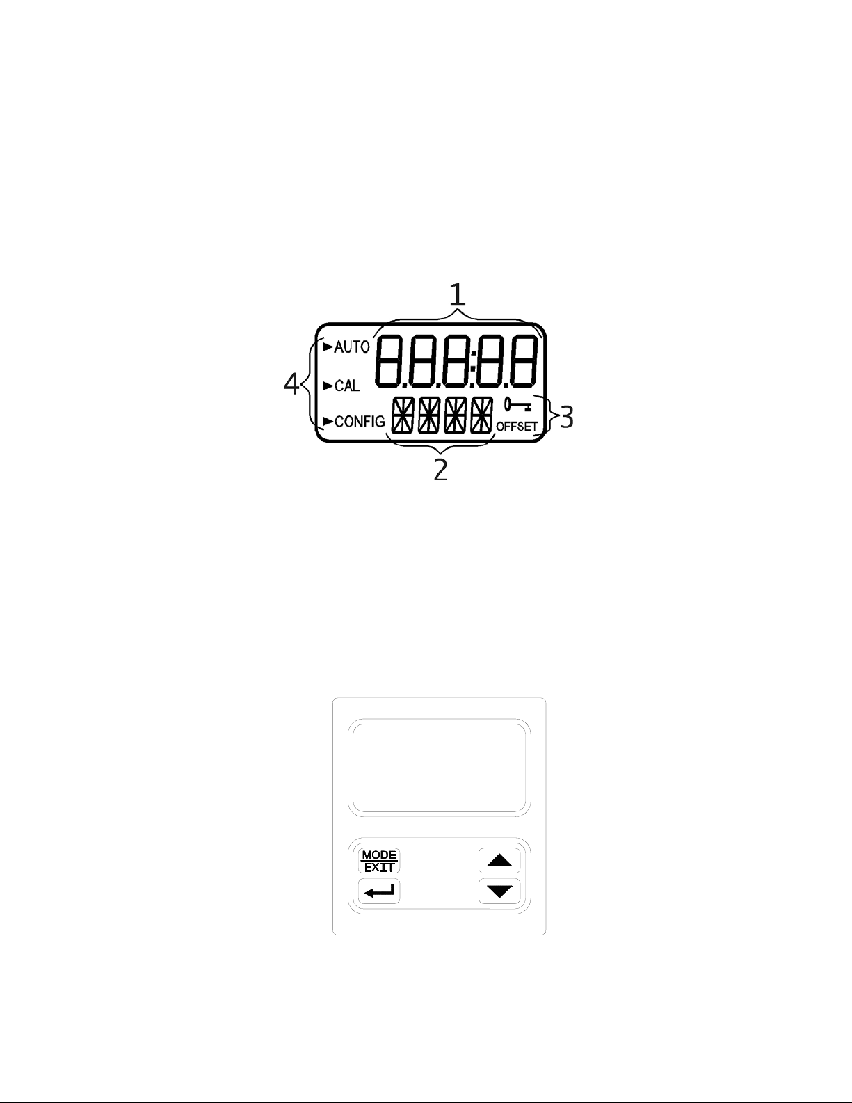
1.2 The Display
Figure 1 illustrates all the items that can appear on the display. The upper row of the
display (1) is used for reporting the %T levels and to provide user guidance in the
customer setting routine. The lower row of the display (2) is used to communicate error
messages and provide user guidance. All error messages will be added to a queue along
with the units (%T). The display has two icons (3) that are used to indicate the use of
access code and offset mode. In addition, mode arrows (4) are used to indicate the current
instrument operating mode; AUTO (automatic operation), CAL (calibration) and CONFIG
(configurations).
Figure 1 – Display used in the instrument.
All items used on the display are shown in this figure
1.3 The Touch Pad
Figure 2 illustrates the touch pad. The touch pad has four buttons: MODE/EXIT, ↵, t,
and u. The MODE/EXIT button is used to cycle among the four operational modes of
the instrument: CAL, CONFIG, SVC and AUTO (Measurement) mode. The ↵ button
enters the option (or mode that is highlighted or chosen. The tand u buttons are used to
change settings.
Figure 2: The AccUView Wastewater touch pad.
AccUView Wastewater (1/09) 3
Rev. 2.9
Page 10
1.4 Vapor Purge
The AccUView Wastewater sensor is equipped with a continuous vapor purge system. A
replaceable desiccant pouch in the lower portion of the instrument dries the air. System
heat is used to warm the air. A fan inside the instrument continuously circulates heated dry
air around the optical well and the flow through cuvette. This feature eliminates the need
for a dry purge line.
The AccUView Wastewater Sensor monitors the replaceable desiccant pouch condition
continuously. The LCD display will show DESC on the lower line in the event that the
desiccant pouch needs replacement. Replacement desiccant pouches are available from HF
scientific or the local representative (Part # 21555R). Refer to section 9.2 Replacing or
Installing the Desiccant Pouch.
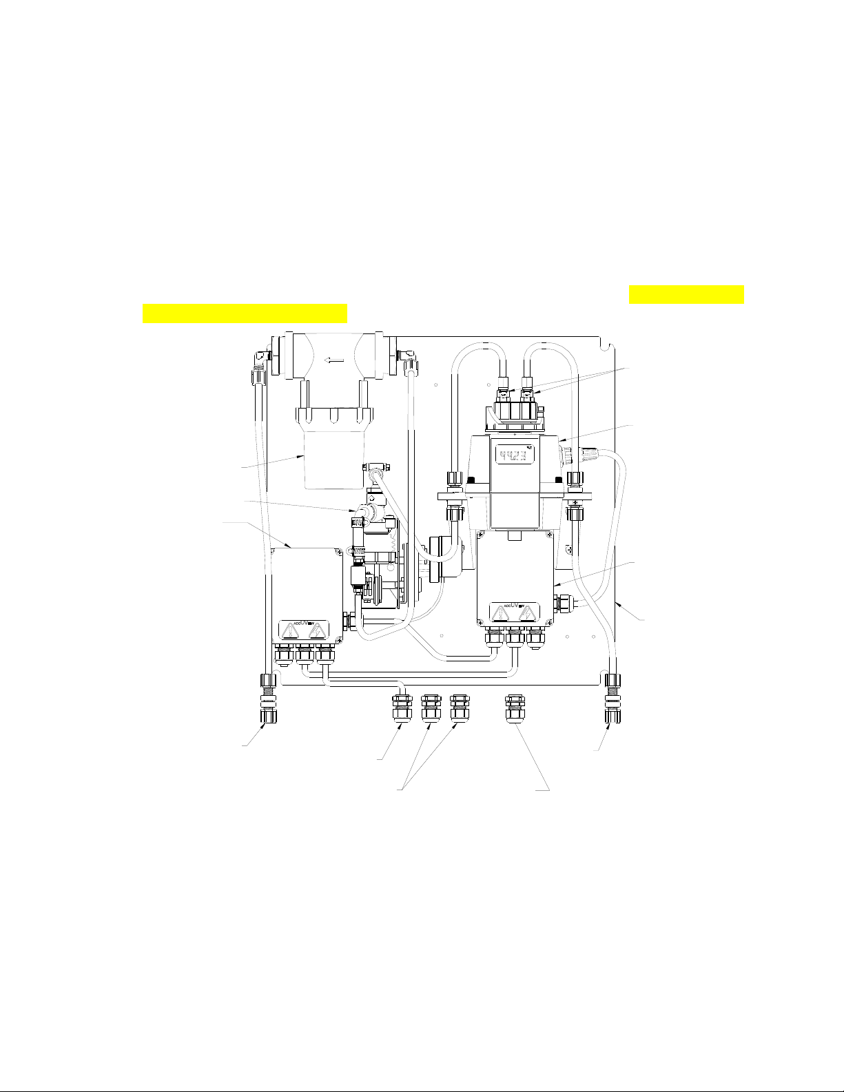
QUICK
DISCONNECTS
T-STRAINER
40 MESH
MAINS
TERMINAL
BOX
PUMP
ACCUVIEW
SENSOR
SENSOR
TERMINAL BOX
BACK PANEL
WATER INLET
100-240 VAC
POWER IN
OUTPUTS
ENCLOSURE VENT
MAIN
DRAIN
Figure 3: The AccUView Wastewater Panel
1.5 The AccUView Wastewater Panel
All of the main components of the system are mounted on a panel inside the stainless steel
enclosure. There is easy access to all serviceable parts. Please note that all terminations
are within separate enclosures. This modular approach enables replacement or service of a
single module without need to return the entire system. Figure 3 shows all the modules.
AccUView Wastewater (1/09) 4
Rev. 2.9
Page 11
2.0 Safety
This manual contains basic instructions that must be followed during the commissioning,
operation, care and maintenance of the instrument. The safety protection provided by this
equipment may be impaired if it is commissioned and/or used in a manner not described in
this manual. Consequently, all responsible personnel must read this manual prior to
working with this instrument.
In certain instances Notes, or helpful hints, have been highlighted to give further
clarification to the instructions. Refer to the Table of Contents to easily find specific
topics and to learn about unfamiliar terms.
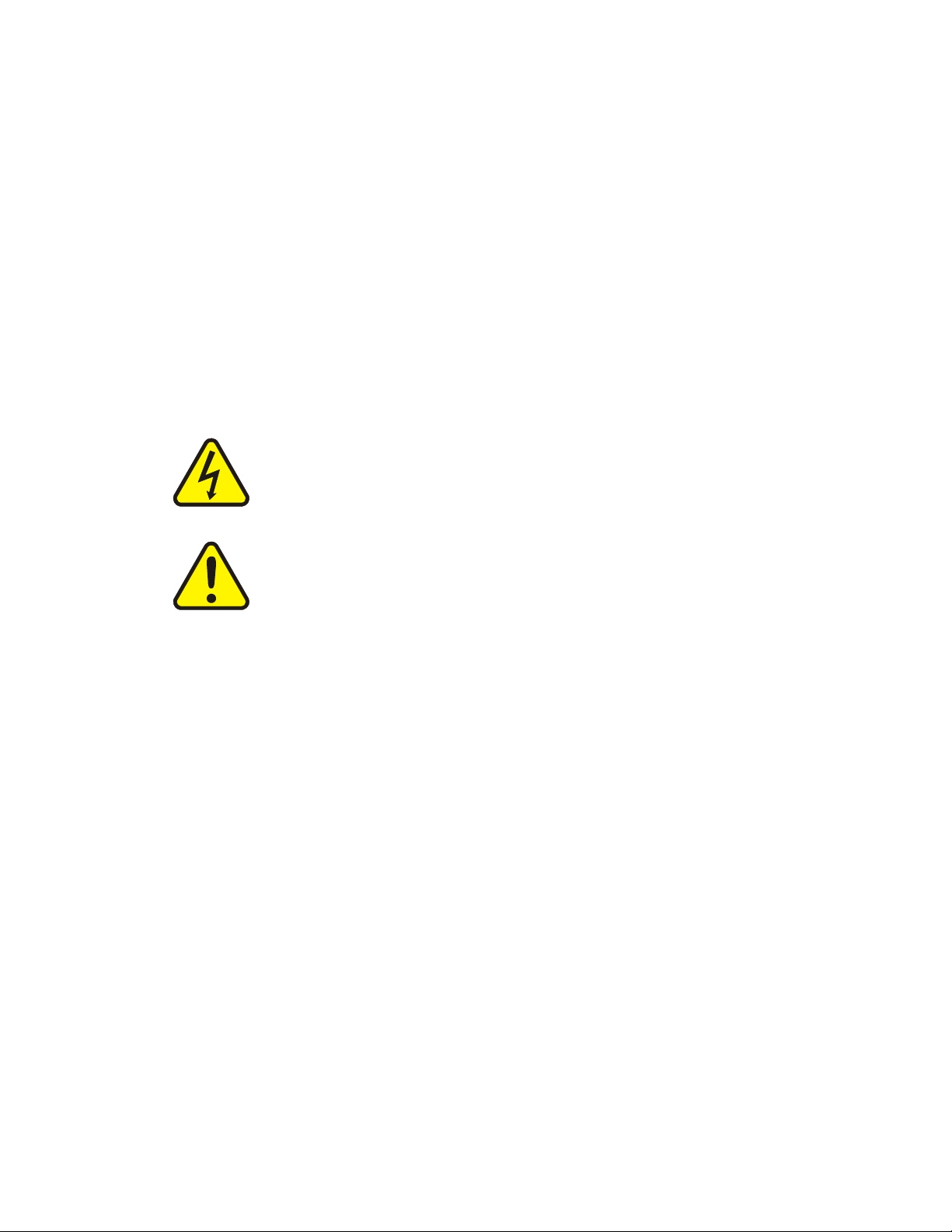
2.1 Symbols used on Instrument & In Manual Standard IEC symbols are used on the high voltage cover.
ISO 3864, No. B.3.6 Caution, risk of electric shock.
cover
This symbol indicates that hazardous voltages may be present under this
This symbol is reminding you to read the sections in the manual referring
to the electrical connections, or other potential hazards.
ISO 3864, No.B3.1 Caution refer to accompanying documents.
AccUView Wastewater (1/09) 5
Rev. 2.9
Page 12
3.0 Installation and Commissioning
Prior to use for the first time, the supplied desiccant pouch will need to be installed. Refer
to section 9.2 Replacing or Installing the Desiccant Pouch.
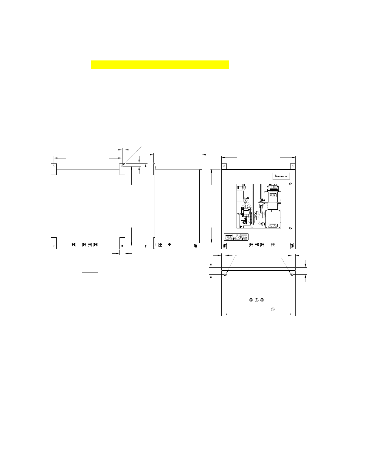
3.1 Mounting & Site Selection
The instrument is designed for wall mounting. For rail mounting, contact HF scientific.
Choose a location that is easily accessible for operation and service. Ensure that the front
display rests at eye level. Please note that the enclosure has tool access door, allow ample
room for this door to fully open. The overall mounting dimensions of the instrument are
shown in Figure 4. The recommended mounting screws are M6 (¼”) for the instrument
enclosure.
(4X)
18,3 [0.72 in]
470,0 [18.50 in]
547,6 [21.56 in]
n10,00 [n.393 in] THRU
332,2 [13.08 in]
19,0 [0.75 in]
585,7 [23.06 in]
508,0 [20.00 in]
508,0 [20.00 in]
36,5 [1.44 in]
NOTE: ALL DIMENSIONS ARE IN
MILLIMETERS, INCH DIMENSIONS ARE IN
BRACKETS.
25,4 [1.00 in]
INLET
OUTLET
(DRAIN)
25,4 [1.00 in]
45,7 [1.80 in]
45,7 [1.80 in]
Figure 4: Overall Mounting Dimensions of the Instrument
For faster response the instrument should be mounted as close as possible to the sampling
point (within 2-3 meters (6-10 ft) of the sampling point).
AccUView Wastewater (1/09) 6
Rev. 2.9
Page 13

3.2 Plumbing
The recommended plumbing for the
instrument is shown in Figure 5. The
internal bellows pump is capable to
drawing water from a depth of 3.6 m
(12 ft). To prevent the system from
clogging, two strainers are used; a
ACCUVIEW
WASTEWATER
UV ANALYZER
foot strainer at intake line and a Tstrainer inside the instrument.
Install the supplied inlet basket
strainer onto the inlet line if the flow
INLET TUBING
of the sample water prevents the inlet
strainer from remaining submerged,
a stand pipe must be used. An
OUTLET RETURN
(DRAIN) TUBING
example of such a system is shown
in figure 5.
Connect the other end of the inlet
tubing to the inlet connec
ccUView Wastewater.
A
tion on the
INLET STANDPIPE ASSY
The main drain connection must be
open to atmosphere. Please ensure
that the drain tubing is connected and
run either to a convenient drain. To
ensure proper operation ensure
re no loops in the drain line.
a
there
INLET STRAINER
(40 MESH)
Figure 5: Recommended Plu
mbing
The sample main drain should NEVER be returned to the stream. This water MUST
be sent to a convenient drain.
The instrument is equipped to be plumbed using 4.75 mm (3/16”) ID, 8 mm (5/16”) OD
flexible tubing. Opaque tubing should be used if the tubing will be exposed to sunlight, to
prevent algae growth.
Install the desiccant pouch before operating the instrument. Refer to section 9.2 Replacing
or Installing the Desiccant Pouch.
AccUView Wastewater (1/09) 7
Rev. 2.9
Page 14

3.3 Electrical Connections
The electrical connections to the instrument are made through the two terminal boxes. The
connections are labeled within the terminal boxes and are self-descriptive (see Figures 6 &
7). Please follow all local and government recommendations and methods for installation
of electrical connections to and between the instrument and other peripheral devices.
Plugs are inserted into bulkheads when shipped, to ensure a watertight seal. These plugs
should be removed and discarded when cabling to these connections.
The power cable bulkhead will accept cable diameters from 5.8mm (.230 in.) up to 10 mm
(.395 in.). All terminals are designed to accept wires in the range of 14-28 AWG. All
wires should be stripped to a length of 6 mm (¼”). A strain relief strap is provided to
reduce tension on the power terminals.
It is the user’s responsibility to assure that the watertight seal is maintained after the
terminal box has been wired for operation. If any of the bulkheads are not tightened
properly around a cable or plug, the ratings of the instrument will be jeopardized and there
is a possibility of creating a shock hazard.
Only qualified electricians should be allowed to perform the installation of the
instrument as it involves a line voltage that could endanger life.
TB4
SOL+
SOL-
PUMP (+)
PUMP (+)
RELAY (NC)
RELAY (NO)
RELAY (COM)
TB1 (A) TB2 (B) TB3
N L
F2 F1
100-240 VAC
47-63 Hz
POWER
TERMINAL
TO CABINET
HEATER (OPT)
STRAIN
RELIEF
POWER
TERMINAL
SENSOR TO
TERMINAL BOX
MAIN POWER
TERMINAL
100-250VAC
47-63 Hz
Figure 6: Mains Terminal Box
3.3.1 Power: All mains connections are made in the mains terminal box. The instrument is
equipped with a 100-240 VAC, 47-63 Hz switching power supply; please verify that the
line voltage falls within these specifications. It is recommended that a circuit breaker be
placed prior to the power connection to allow for service. While making connections, refer
to Figure 6. The AccUView Wastewater is supplied with a power cord for 120 VAC
which is UL and CSA approved.
AccUView Wastewater (1/09) 8
Rev. 2.9
Page 15

POWER SUPPLY
TERMINAL BLOCK
ALARM
TERMINAL BLOCK
240 VAC, 2A
PUMP
TERMINAL BLOCK
12 VDC
4-20ma / RS485
TERMINAL BLOCK
SENSOR TERMINAL BOX
(WITH LID REMOVED)
POWER CABLE
STRAIN RELIEF
Figure 7: Sensor Terminal Box
3.3.2 RS-485 (optional): The connection for the RS-485 may be made in the sensor
terminal box (see figure 7). The RS-485 Modbus or special protocol half-duplex (2-wire)
digital interface operates with differential levels that are less susceptible to electrical
interferences. This is why cable lengths up to 3000 ft can be implemented. The last
device on each bus may require terminating with a 120-ohm resistor to eliminate signal
reflection on the line. Do not run RS-485 cables in the same conduit as power.
To prevent damage to the instrument, ensure that power is disconnected prior to making
connections. For ease of connecting, remove the plug in terminal block. Connections are
labeled beneath this termination.
This factory installed option is available (HF catalog #19851A). Please note that adding
this option deletes the standard isolation on the 4-20 mA output.
3.3.3 Relay: Connections for the relay are located in the sensor terminal box (see figure
7). The Alarm relay is a mechanical relay rated at 240 VAC 2A. Please note that the relay
is labeled NO (Normally Open), NC (Normally Closed) and C (Common). As this alarm is
configured fail-safe, the normal condition is with power applied to the AccUView
Wastewater and in a non-alarm condition. Operation of this alarm is covered in section 7.4
Configuring the Alarm.
3.3.4 4-20 mA: Connection to the 4-20 mA is made inside the sensor terminal box (see
figure 7). The 4-20 mA output is driven by a 15 VDC power source and can drive recorder
loads up to 600 ohms. Do not run 4-20 mA cables in the same conduit as power. Operation
of this output is covered in section 7.2 Setting the 4-20 mA. The outputs are equipped
standard with an installed looped powered isolator (500V isolation).
To prevent damage to the instrument, ensure that power is disconnected prior to making
connections. For ease of connecting, remove the plug in terminal block. Polarity of the
connections is labeled beneath this termination.
AccUView Wastewater (1/09) 9
Rev. 2.9
Page 16

4.0 Operation
This process monitor allows for the measurement of the transmission of process water online. Process water is usually reported in units of %T. Readings above 102 %T are
indicated by a flashing display. Readings above 100 %T indicate that the current sample is
better than the calibration water. Readings above 102 %T will cause an alarm condition to
occur where the relay will change to the alarm condition and the 4-20 mA will change to 2
mA. Readings above 110 %T are not possible. All readings are mathematically path length
corrected to 1cm.
The AccUView Wastewater has an internal pump to draw sample water from a stream. To
extend system life and reduce maintenance it operates in a cycle. In the default cycle, the
pump runs for five minutes every 30 minutes. After the pump stops, the system waits for
the sample to degas then takes a reading. The reading will only be updated once every
cycle.
4.1 Modes of Operation
There are four operational modes, AUTO, CAL, CONFIG and SVC. All modes can be
accessed by sequentially pushing the MODE/EXIT key.
Note: Before entering AUTO mode, the lower portion of the screen will alternate between
AUTO and ↵. This is a pre-Auto condition indicating that the ↵ button must be
pushed before normal operation can begin. The pump will start after the ↵ button is
pushed as all timers are reset.
During normal operation, the instrument will have the arrow beside AUTO (automatic
operation) and AUTO will be flashing. The scale (%T) is displayed on the lower row of
the display and the measured reading on the upper row of the display (see illustration
below). The flashing AUTO indicates that the ultrasonic cleaning is operating correctly.
In this mode the pump will cycle and readings will be taken.
During calibrations the CAL (calibration) mode will be used. This mode is indicated by an
arrow beside the CAL. See section 5.0 Instrument Calibration.
The CONFIG (configurations) mode is used to change operation of the instrument, or
alter the outputs. This mode is indicated by an arrow next to CONFIG on the LCD. See
section 7.0 Instrument Configuration (CONFIG mode).
The last operation mode is SVC (service) mode which is used when it is not desired for
the pump to operate. This mode can be used to perform various maintenance procedures.
AccUView Wastewater (1/09) 10
Rev. 2.9
Page 17

4.2 Warm-up
Upon power-up the AccUView Wastewater will require a warm-up period of about 60
minutes. For improved accuracy allow the AccUView Wastewater to complete warm-up
time prior to calibrating. During the warm-up period, the display may flash indicating that
it has detected a temperature change. It is normal for this to occur during the warm-up
period
4.3 Routine Measurement
Assuming that the instrument has been wired and plumbed as specified in section 3.0
Installation and Commissioning, the operation is quite simple.
The following steps describe how to measure the %T of a sample using this instrument:
1. Apply power to the instrument and allow the unit an initial warm up of 1 hour.
2. When the pump has run through the first cycle the instrument will display the
measured %T level of the sample by displaying it on the LCD screen. As this reading
is buffered allow several cycles for best accuracy. After the first hour of operation the
instrument should be warmed up and displaying accurate readings. In addition to the
display, the equivalent signal is provided on either the analog (4-20 mA) output, or the
digital output, depending on the options selected. These signals can be directed to
appropriate SCADA, PLC or recording device.
Note: A flashing display may occur after warm-up. This is an indication that either the
ambient or the water temperature has changed rapidly. During this time the
readings may be slightly out of the specified accuracy. The AccUView Wastewater
will automatically compensate as soon as the rate of temperature change slows.
4.4 Security Access Feature
The instrument is equipped with a security access code feature that can be activated in the
configuration mode. If the security feature is enabled, the screen shown in the illustration
below will appear when the MODE/EXIT button is pressed.
The security code (333) must be entered to gain access to CAL or CONFIG menus.
Notice that the first number in the code is flashing. The flashing indicates that this is the
AccUView Wastewater (1/09) 11
Rev. 2.9
Page 18

number to be entered. Use the t
the code and then press the ↵ button to accept the first number of the code. Now enter the
second number in the code. Proceed as with the first number followed by ↵. Then repeat
the process for the third number in the access code, and finish with the ↵ button.
If the valid access code has been selected, the instrument will be directed to the calibration
mode. If the wrong access code is selected, the instrument will return to the AUTO mode.
Refer to section 7.6 Enabling the Security Access for more information.
or u arrows to select the first of the three numbers in
AccUView Wastewater (1/09) 12
Rev. 2.9
Page 19

5.0 Instrument Calibration
The instrument was calibrated and tested prior to leaving the factory. Therefore, it is
possible to use the instrument directly out of the box. Under normal conditions, recalibration is recommended at least once every month. To get the greatest accuracy
calibration may be required once per week.
Two cuvettes and two flow through units are supplied with the instrument so that they can
be exchanged with each other. One cuvette and flow through unit should always be kept
clean for replacement when calibrating.
Relay contact is held at the last valid condition and will not change state while the
instrument is in the calibration and/or in the configuration mode. While in the calibration
mode, the instrument has a time-out feature that automatically returns the system
operation to the AUTO mode after a fifteen (15) minute period of inactivity.
5.1 100%T Calibration
1. Select the calibration function of the instrument by pressing the MODE/EXIT button once.
The arrow beside CAL will be illuminated on the display. The lower display shows
alternating 100 (indicating that the 100%T standard is requested) and ↵.
2. Remove the flow through assembly by releasing the quick connect fittings then releasing the
flow through clamp. Retain this flow through unit for future cleaning and use.
3. Install the clean, dry flow through unit in which the cuvette is filled with 100%T calibration
fluid. Do not connect the quick connect fittings at this time, but lock the flow through down.
4. Press the ↵ button to accept the calibration.
5. The lower display will count down the progress of the calibration step.
6. At the end of the count, the instrument will switch to pre-AUTO. The pump will not start in
this mode. Connect the quick connect fittings at this time.
7. Press the ↵ button once to enter AUTO and resume normal operation.
8. After the instrument has returned to AUTO, the pump will run through a cycle.
9. Moving a flow head after calibrating will affect the accuracy of the reading.
Note: It is recommended that the flow through unit be removed for as short an interval as
possible to prevent premature saturation of the desiccant.
Warning: Even thought the UV lamp is low in power, it is still recommended to avoid
looking directly into the optical well while the flow through unit is removed.
AccUView Wastewater (1/09) 13
Rev. 2.9
Page 20

5.2 100%T Calibration Error If the screen shown below is displayed after the 100%T calibration, the internal diagnostics have determined that the calibration fluid requires replacement or the flow through cuvette requires replacement. Check the calibration fluid & cuvette, then recalibrate or restore the factory calibration see 6.1 Restoring Factory Settings. The instrument cannot be used without performing one of these operations.
To recalibrate press the MODE key and start the calibration sequence again. To restore the
factory calibration, push and hold the tbutton. Now push and release the ↵ then release
the tbutton. See section 6.1 Restoring Factory Settings
AccUView Wastewater (1/09) 14
Rev. 2.9
Page 21

6.0 Instrument Offset
In certain instances, it may be desirable to use an offset factor to calibrate the instrument
rather than performing a physical calibration of the instrument (as described in section
5.1). This procedure is not recommended in lieu of regular instrument calibration but it
can be used in situations where the number of instruments used makes regular calibration
prohibitive. This calibration technique will make the instrument accurate only at levels
near the measured value of the grab sample and not in the full range of the instrument.
Note that the OFFSET icon will be illuminated whenever an offset used. The maximum
offset is ± 1.0 %T If instrument variation is greater than 1 %T a full calibration is
recommended.
The procedures are as follows:
1. Collect a grab sample of the process water that is being monitored by the instrument
and record the reading reported by the AccUView Wastewater.
2. Take the grab sample and measure its value using a laboratory photometer (contact the
HF scientific customer services department for examples of laboratory photometers).
3. Compare the reading reported by the AccUView Wastewater to that obtained in the
laboratory. If the readings are very close, then no offset adjustment or calibration is
required and the procedure may be stopped at this step. However, if the readings are
substantially different (but less that 1 %T) continue on in this procedure to utilize the
offset option to improve the reading of the AccUView Wastewater so that it will agree
with the laboratory reading between calibrations.
4. Select the offset function of the instrument by pressing the MODE/EXIT button until
the arrow beside CONFIG is illuminated on the display. Refer to the following screen.
5. Push the ↵ button until OFST is displayed on the lower row.
6. At this point, the lower row of the display will indicate the operational status of the
offset function (On or OFF). Change this status by using the t and u buttons.
Once the desired operational status of the offset function has been set, press the ↵
button to accept it. If the option was turned off, return to pre-AUTO mode by
pressing MODE/EXIT. Then press the ↵ button to return to normal operation.
7. If the option was turned On, the upper row will display the offset required. This will
AccUView Wastewater (1/09) 15
Rev. 2.9
Page 22

add or subtract the value of the offset to the measured %T value. As an example if the
AccUView Wastewater measures the process at 92.6 %T but the laboratory instrument
read the sample at 92.2 %T, adding an offset of -0.4 would result in the AccUView
Wastewater displaying 92.2 % T.
Select the desired offset level using the t and u
been set, press the ↵ button to accept it.
8. This completes the offset configuration.
9. At this point, the instrument will continue through the configuration (CONFIG) mode
of the instrument or press MODE/EXIT to return to the pre-AUTO mode. Then press
the ↵ button to return to normal operation.
Note: This offset will remain in effect until it is turned off. It is not cancelled after a
calibration.
6.1 Restoring Factory Settings
If the instrument is unable to perform a calibration due to a low lamp output, bad
calibration standard or a dirty cuvette, the instrument will display CAL on the lower row
of the display and Err on the upper row. The operator has two choices to correct this
problem. If the operator can determine whether a poor calibration or a low lamp caused
the problem, he/she can remedy the problem and recalibrate. If all else fails, the operator
may restore the factory calibration and configuration settings by performing the following
operation. Push and hold the tbutton. Now push and release the ↵ then release the
tbutton. Factory calibration and factory configuration have now been restored.
Note: Restoring the factory settings allows the use of the AccUView Wastewater with
reduced accuracy. The original problem still exists and must be determined and
corrected before accurate operation of the AccUView Wastewater will be resumed.
buttons. Once the desired level has
AccUView Wastewater (1/09) 16
Rev. 2.9
Page 23

7.0 Instrument Configuration (CONFIG mode)
The instrument has been designed to provide the ability to customize the instrument
according to needs at any time during normal operation. This mode has been split into
sub-menus to facilitate instrument configuration. This section describes how to use each
of the sub-menus to configure the instrument. While in the configuration mode, the
instrument has a time-out feature that automatically returns the system operation to the
AUTO mode after a fifteen (15) minute period.
Enter the CONFIG mode of the instrument by pressing the MODE/EXIT button until the
arrow beside CONFIG is illuminated, then press the ↵ button.
Note: To exit the CONFIG mode, press the MODE/EXIT button.
7.1 Selecting the Output (O/P)
The first configuration selection is the O/P. The selections are 4-20 for the 4-20 mA
output, 485 for the RS-485 and OFF if no outputs are required. Select the desired output
by using the t and u buttons. Once the desired output has been set, press the ↵ button
to accept it. The next prompts will depend on the output selected.
7.2 Setting the 4-20 mA
If the 4-20 mA output was turned on, prompts to set the lower (LOLM) and upper
(UPLM) %T limits corresponding to the 4 mA and 20 mA output levels will be displayed.
The first prompt will be the limit assigned to the 4 mA output level:
Select the level to assign to the LOLM using the t and u buttons.
Once the desired level has been set, press the ↵ button to accept it.
AccUView Wastewater (1/09) 17
Rev. 2.9
Page 24

The next, prompt will be the level assigned to the 20 mA output level (UPLM on the
lower row of the LCD display). Select the %T level to assign to the UPLM using the t
and u buttons. Once the desired level has been set, press the ↵ button to accept it.
The final prompt for the 4-20 mA setup is for the error level (ERLV). This is the current
level that the instrument will output when an error occurs for possible errors see section
10.1. The error level selections are 0.00 mA, 2.00 mA, 4.00 mA , or OFF to disable this
feature. The default setting is 2.00 mA.
7.3 Configuring the RS–485 Port
If the instrument is equipped with this option (HF cat # 19851A), and the I/O selection is
changed to 485, prompts will appear for setting the baud rate and the address.
Select the correct baud rate (1200, 2400, 4800, 9600, or 19200) for operation of the I/O
port by pressing the t or u buttons to change the displayed baud rate.
Press the ↵ button to continue on and select the desired instrument address using the t or
u buttons. Once the selection is made, press the ↵ button to save the setting.
AccUView Wastewater (1/09) 18
Rev. 2.9
Page 25

To enable the Modbus mode, select ASCII or RTU. For more information refer to the
Modbus Manual (Catalog #24570). The manual is also available as a free download from
our website at www.hfscientific.com
7.4 Configuring the Alarm
A relay is provided and is designed to operate as an independent programmable alarm.
Two types of information must be input to fully program the alarm:
1. The alarm function (HI, LO, or OFF)
2. The alarm set point (level at which the alarm activates)
These are described below:
Alarm Function: The alarm can either be turned OFF or programmed to operate in one
of two different manners:
1. HI alarm: the relay changes state when the measured %T level is higher than the
programmed alarm level for a prescribed amount of time.
2. LO alarm: the relay changes state when the measured %T level is lower than the
programmed alarm level for a prescribed amount of time.
.
Note: The relay automatically changes state when an internal system failure is detected.
Alarm Set Point: The level at which an alarm activates is called the alarm set point. On
the instrument, the alarm set point is designated as “S/P”. The set point is adjustable to
any valid level over the range of the instrument in steps of 0.1%T.
7.5 Offset Calibration
Refer to section 6.0 for more information on this selection.
AccUView Wastewater (1/09) 19
Rev. 2.9
Page 26

7.6 Enabling the Security Access
The instrument is equipped with a security access. If this option is turned on, the user is
required to input the access code into the instrument to get to any mode other than AUTO.
The only code is 333. This code may not be changed. See section 4.4 for more
information on this security feature. The security key icon will be visible and flashing on
the display whenever the access option is selected using the t or u buttons. (On or
OFF).
7.7 Extended Settings
The last few settings are grouped together to prevent them from being adjusted by
accident. To gain access to the extended settings, select On using the t or u buttons and
press the ↵ button.
7.8 Speed of Response
The speed of response for both displayed and output values can be adjusted in this menu.
The default setting is 10 however, 100 response speeds are available. Select the desired
speed of response using the t and u buttons. Press the ↵ button to accept it.
To avoid reading anomalies, select the slowest speed (highest number). Select the fastest
response where monitoring of rapid changes is needed.
AccUView Wastewater (1/09) 20
Rev. 2.9
Page 27

7.9 LCD Backlight Brightness
The LCD backlight brightness may need to be adjusted. This is of particular interest if
multiple instruments are located in the same area and it is desired for the entire group to
have the same appearance. Ten levels are available. The default brightness is 8.
Change the brightness by pressing the t or u button. When the desired brightness has
been selected, press the ↵ button.
7.10 Ultrasonic Cleaning
This allows for a selection menu to turn OFF the ultrasonic cleaning function if desired.
The default mode is On. Make a selection using the t and u buttons then press the ↵
button.
7.11 Pump Period
This is the over all time in minutes for cycle. The default is set to 30 minutes, which
means the pump will draw a new sample every 30 minutes. The adjustment range is 1 to
60 minutes.
AccUView Wastewater (1/09) 21
Rev. 2.9
Page 28

7.12 Pumping Time
This is amount of time in minutes the pump will operate in each pump cycle. The default
is set to 5 minutes. If no changes are made to pump settings the pump will run for 5
minutes every 30 minutes
7.13 Settling Time
This is the period of time in seconds where the sample is allowed to settle or degas prior to
measuring. The default setting is 20 seconds and adjustment is allowed from 1 to 60
seconds.
7.14 Measurement Time
This portion of the cycle is where the actual measurements are taken. Measurements are
taken during the lamp on time (once every 10 seconds). The default setting of 60 seconds
allows for 6 consecutive readings all of which are added to the averaging buffer.
Allowable adjustment is from 20-150 seconds.
AccUView Wastewater (1/09) 22
Rev. 2.9
Page 29

7.15 Desiccant Alarm
When the humidity detector in the AccUView Wastewater indicates that the internal
environment is close to the point where humidity could cause condensation, the instrument
will display DESC as a warning. If desired, a desiccant warning can activate the alarm and
send the 4-20mA to 2mA. To activate the alarm when the desiccant fails, select On in the
DESC menu. The default for this menu is OFF. Make selections using the t and u
buttons then press the ↵ button to move to return to pre-AUTO mode. Then press the ↵
button to return to normal operation.
7.16 Saving Configuration Settings
If extended settings is set to OFF, pressing the
AccUView Wastewater will be sent to pre-AUTO mode. Press the ↵ button to return to
normal operation.
↵ button will save all settings and the
If extended settings is set to On, after the last menu of the extended settings, pressing the
↵ button will save all settings and the AccUView Wastewater will be sent to pre-AUTO
mode. Press the ↵ button to return to normal operation.
The CONFIG menu may be used at any time to reset or change any of the parameters.
The CONFIG menu may be exited at any point in the menu by using the MODE/EXIT
key. Any features that have been modified will be saved.
AccUView Wastewater (1/09) 23
Rev. 2.9
Page 30

8.0 Additional Features and Options
8.1 Ultrasonic Cleaning
This system is used to continuously clean the flow through cuvette. It is not intended to
clean cuvettes that are already dirty, or replace manual cleaning entirely. The system will
increase the time between cleanings dramatically. Please note that the system requires the
use of a special cuvette. This cuvette must be used for the system to operate correctly.
The system works by sending an ultrasonic frequency through spring connections into a
piezo transducer bonded to the bottom of a flow through cuvette.
The system can detect that an incorrect cuvette is installed, an error has occurred in the
transducer or the transducer is not making contact with the spring connections. This error
is indicated by CLN being posted to the lower screen. Since this is an error condition, the
alarm will be set and the 4-20 mA will be sent to 2 mA.
If the correct cuvette is installed, and the error is still posted, try rotating the flow through
unit slightly to improve the connection. If this fails to work, the cuvette may have to be
replaced (Catalog #24232S). The detection for this cuvette only operates in AUTO mode.
If the system is operating correctly AUTO will flash. The cleaning system can be turned
off. Refer to section 7.10 Ultrasonic Cleaning
After installing a cuvette, there will be a 30 minute period where the lower screen will
post DRY to the lower screen. During this time, the ultrasonic circuit will not operate to
allow the Vapor Purge system to remove all moisture from the ultrasonic transducer. This
is normal and is not considered an alarm condition so no alarm will be implemented. If the
cuvette is removed during this period no CLN alarm is posted until the 30 minute DRY
period times out.
Even with the above drying system, it is still recommended that Ultrasonic cuvettes be
dried by hand, including the transducer on the bottom prior to use.
8.2 RS-485 Outputs (19851A)
The AccUView Wastewater has the capability to operate in three different RS-485 modes.
Included is a mode for interfacing into the HF Online software package (section 8.2.1
below), and a simple communication mode. A third operating mode is the Modbus
communications. All modes will automatically configure and do not require any changes
or selections. Factory installed option cat. # 19851A is required for RS-485 operation.
8.2.1 HF Online (HF catalog # 19783)
The AccUView Wastewater can operate as a small SCADA system with an optional PC
software package, called HF ONLINE. This system allows for an interface with up to 255
AccUView Wastewater’s for the purpose of data logging. This system will interface
directly with common database and spreadsheet software.
AccUView Wastewater (1/09) 24
Rev. 2.9
Page 31

8.2.2 Simple Communication
The AccUView Wastewater can provide basic communications over simple programs
such as the Hilgraeve HyperTerminal that is included with most Microsoft Windows
packages. The user could also use Visual Basic or other programs. The default
communication parameters are 8 bits, no parity and 1 stop bit. These parameters may be
changed in the extended CONFIG menu.
The master computer will send out:
• Byte #1 the attention character “:” in ASCII or 3A Hex
• Byte #2 the address of the AccUView Wastewater being queried
• Byte #3 & 4 CR LF or 0D 0A in hex
The AccUView Wastewater will respond with:
• The same attention character “:” in ASCII or 3A Hex
• The address of the AccUView Wastewater
• The Reading
• The Unit (% T )
A sample communication would look like this:
(Master computer requesting a report from address #1) : 1 CRLF
(AccUView Wastewater set to address #1 Response) :001 97.4 %T
8.2.3 Modbus Communication
Modbus communications is fully operational if the RS-485 option (Catalog #19851A) is
installed. The Modbus protocol communication information is covered in a separate
manual (Catalog #24570). This manual is available as a free download from our website at
www.hfscientific.com
8.3 Remote Panel Meter (Catalog # 19609)
The remote panel meter allows for remote indication of the %T reading using the 4-20 mA
loop. No external power is required as the meter is run off of the 4-20 mA source.
8.4 Heater Option – Model # 19571C
This factory installed option allows the AccUView Wastewater to be used at lower
temperatures where light freezes may occur. This option includes two 30W radiant heater
elements controlled by an adjustable thermostat. The use of this option extends the
operation of the AccUView Wastewater down to ambient temperatures of -10°C. The
thermostat should be set to about 15°C - 20°C to allow the heaters enough time to
compensate to dropping temperatures.
To prevent water from freezing in source and drain lines, solenoid valves close during
pumping and open to the atmosphere after pumping. This prevents water from being held
in the lines and thus prevents the lines from freezing up.
AccUView Wastewater (1/09) 25
Rev. 2.9
Page 32

9.0
Routine Maintenance
The hydraulic loop through the AccUView Wastewater is fairly simple. This simplicity
keeps cleaning intervals to a minimum.
The chart below shows suggested maintenance periods. As each installation is different,
some maintenance periods will vary. It is recommended to always monitor the flow on a
daily basis and replace tubing on annual basis.
Maintenance Required Daily Weekly Monthly Every 3 Months/As
Needed
Check Flow at Main Drain X
Check T-Strainer X
Check Cuvette Cleanliness X
Check Display for Desiccant
Replacement Indication
Clean T-Strainer X
Clean Inlet Basket Strainer X
Calibrate & Replace Flow Through X
Replace Desiccant X
Clean Entire System X
Replace System Tubing X
9.1 Cleaning the Flow Through & Cuvette Measurement cuvettes used for the flow through should be clean and free of marks or scratches. Cleaning is accomplished by cleaning the interior and exterior with a detergent solution and then rinsing several times with distilled or de-ionized water. A 5% solution of phosphoric acid will help remove hard water or calcium deposits. Generally the flow through unit will need to be rinsed. As a safety precaution a mild chlorine solution should be used on both the cuvette and flow head to provide some disinfection. Always rinse the parts completely with distilled or de-ionized water.
9.2 Replacing or Installing the Desiccant Pouch The AccUView Wastewater continuously checks the condition of the desiccant. When the desiccant gets in such a condition that it may cause problems, the instrument will display DESC on the lower portion of the display to indicate the presence of humidity.
X
Yearly
Proper use of the supplied desiccant is essential in maintaining
the performance of the instrument. The desiccant has been
designed to have a long life; however, replacement of the
desiccant pouch will be required from time to time.
It is essential that the enclosure seal be maintained to ensure
adequate desiccant life. Inspect the enclosure seal each time
the desiccant pouch is replaced. Replace any parts found to be
defective. Figure 8: Desiccant Pouch
AccUView Wastewater (1/09) 26
Rev. 2.9
Page 33

The desiccant should be replaced when the instrument displays DESC. A new sealed
desiccant pouch and indicator card are available from HF scientific part #21555R. To
initially install or remove the old desiccant, simply unscrew the four corner thumbscrews
and remove the electronics half of the instrument. Open the bag protecting the new
desiccant pouch and replace (or install) immediately. To speed up the recognition, by the
instrument, of the new desiccant it will be necessary to reset the instrument by
disconnecting the sensor interconnect cable for 2 seconds and then reconnecting it.
Once the bag is opened, install the desiccant pouch immediately to prevent
premature degradation of the desiccant.
9.3 Replacing the Source Lamp
The UV source lamp in the AccUView Wastewater has a rated lamp life of about two
years under normal use.
Due to safety concerns it is recommended that the electronic service module be exchanged
- Part# 24669S. Whenever the UV source lamp requires replacement an economical
exchange program is available. Call the HF Customer Service Department for assistance.
9.4 Pump The bellows pump is designed for long life. Generally little maintenance is required; however, the check valves will occasionally require removal for cleaning. It is normal for the bellows to discolor. The bellows life is rated for several years of operation. Contact HF scientific if bellows replacement is needed.
9.5 T-Strainer The T-strainer will require cleaning when full of debris. The cleaning period will be dependent on the pump operation period and the amount of debris in the water. When the level exceeds the visual area, the system should be placed into SERVICE mode (SVC) to prevent the pump from cycling. Pull the T-strainer out of the clip and hold over a bucket to catch the water and debris. Rinse the T-strainer bowl and clean or replace the screen. Ensure the bowl seal is replaced. After replacement, dry off any external moisture. Change the operation mode to AUTO to resume normal operation. Check for leaks.
9.6 Inlet Strainer
The inlet strainer prevents most of the solids from entering the system. Generally no
maintenance will be required as long as flow through the system is evident. If this strainer
clogs no sample water can enter the system. This strainer can be cleaned in two ways. The
best method is to pull it up and wash it off with fresh water. Where this is not practical,
back washing with fresh water can be performed. Do not apply high pressure to the tube as
it may rupture.
9.7 System Tubing Replacement
Although the internal system tubing should last a long time, an annual system tubing
replacement will ensure a reliable system. Inspect the condition of the tubing for any
evidence of deterioration. A replacement system tubing kit part # 24700S is available.
AccUView Wastewater (1/09) 27
Rev. 2.9
Page 34

9.8 System Cleaning
The suggested cleaning period is once every three months. As this is very site specific, this
period will have to be adjusted as required.
Cleaning is recommended with chlorine to remove algae and then a Lime-A-Way to
remove calcium and lime. The system should be flushed after cleaning with each solution.
Steps:
1. Press the MODE/EXIT key to change the instrument to the SVC mode. This will
ensure the pump will not start.
2. Disconnect the main drain and inlet tubings.
3. Install shorter tubings to perform the cleaning locally. These should be just long
enough to reach a bucket placed under or near the system.
4. Clean the T-Strainer. As described in section 9.5 above.
5. Drop both the source line and the drain line into a bucket containing 6% Sodium
Hypo chloride (bleach) solution.
6. Initiate a pump cycle by pressing the MODE/EXIT key to switch to the pre-
AUTO mode, and then press
pump to run through its full pumping cycle.
7. Press the MODE/EXIT key to change the instrument to the SVC mode. then
transfer the source line into a container at least 8 liters (2 gallons) of clean water.
Route the drain either to another container or to a convenient drain.
8. Initiate a pump cycle by pressing the MODE/EXIT key to switch to the pre-
AUTO mode, and then press ↵ to return to AUTO and run the pump. Allow the
pump to operate until the container is empty.
9. Press the MODE/EXIT key to change the instrument to the SVC mode.
10. Drop both the source line and the drain line into a bucket containing a solution of
50% Lime-A-Way and 50% water.
11. Initiate a pump cycle by pressing the MODE/EXIT key to switch to the pre-
AUTO mode, and then press ↵ to return to AUTO and run the pump Allow the
pump to operate through its full pumping cycle.
12. Flush by repeating steps 7-9 above.
13. Reconnect the normal inlet and main drain lines.
14. Switch to AUTO mode to continue normal operation.
↵ to return to AUTO and run the pump. Allow the
AccUView Wastewater (1/09) 28
Rev. 2.9
Page 35

10.0 Troubleshooting
10.1 AccUView Wastewater Fault Detection
The AccUView Wastewater performs continuous diagnostic monitoring. In the
AccUView Wastewater there are three levels of fault detection; warnings, errors and
failures. Any faults are displayed in a queue form in the bottom row of the LCD.
A warning is simply a screen indication of a problem. No alarm is activated. If the
desiccant alarm is turned off and the desiccant becomes saturated, a screen warning of
DESC will appear.
An error indicates a fault or a problem that usually can be corrected by the operator.
These errors consist of lamp low output (LAMP), 4-20 mA loop open (MA), bad 100%T
calibration (CAL Err), if desiccant alarm activated and replacement required (DESC). An
additional message will indicate that the ultrasonic transducer is not making contact or the
flow through has been removed (CLN). If any of these conditions occurs, the alarm relay
will be activated and the 4-20 mA output will be sent to the ERLV setting. See section 7.2.
If any of these errors occur the instrument will still display readings, however the accuracy
is not known and the instruments readings should not be trusted.
A failure is a system fault. This is NOT a problem that the operator can correct, and the
unit must be returned to the factory for service. These failures consist of failures in the
CPU, A/D, EEPROM or other devices internal to the instrument (FAIL). If a failure
occurs, the instrument will not function properly and will display the word FAIL on the
lower row, the alarm relay will be activated and the 4-20 mA output will be sent to the
ERLV setting. See section 7.2 .
If any fault conditions occur, the message indicating the fault will be shown on the lower
row of the display.
At power-up for 30 minutes and at operating temperatures outside of our specifications,
the %T reading may flash. When this happens the reading may be outside of the stated
tolerance
10.2 System FAIL Message
Normally, this condition indicates that the instrument will require servicing. Contact either
the HF scientific Technical Service Department or the HF scientific Customer Service
Department.
HF scientific
3170 Metro Parkway
Fort Myers, Florida 33916-7597
Phone: (239) 337-2116
Fax: (239) 332-7643
Email: HFinfo@Watts.com
www.hfscientific.com
AccUView Wastewater (1/09) 29
Rev. 2.9
Page 36

10.3 Wiring Diagrams
These diagrams show the wiring for the AccUView Wastewater with the Heater Option.
For systems without the heater option omit the drain valves, thermostat, heaters and
related wiring, and terminal rails.
SOL+
RELAY (NC)
RELAY (NO)
F2 F1
TB1 (A) TB2 ( B) TB3
N L
TB4
PUMP (+)
100-240 VAC
47-63 Hz
SOL-
PUMP (+)
RELAY (COM)
Figure 10: Main Panel Wiring – Heater Option Shown
AccUView Wastewater (1/09) 30
Rev. 2.9
Page 37

SOL+
RELAY (COM)
PUMP (+)
RELAY (NC)
RELAY (NO)
LLL L
TO HEATER
TERMINAL
BLOCK
BLUE
BROWN
GREEN/YELLOW
100-240 VAC
47-63 HZ
175 VA
Figure 11: Power Box Wiring
10.4 Diagnostic Chart
Symptom Cause Cure
Lower display shows MA
Lower display shows DESC
Lower display shows LAMP
Lower display shows CLN
Lower display shows CAL Err
after a calibration.
Lower display shows FAIL
Readings are lower than expected
4-20 mA loop open Check wiring. See sections 3.3.4
Desiccant pouch bad Change desiccant pouch. See
Lamp failed Replace lamp. Refer to section 9.3
Ultrasonic cleaning failure Refer to section 8.1
100%T Calibration failure Refer to section 5.2
Major system fault Refer to section 10.1 & 10.2
(1) Bubbles in solution
(2) Condensate or leaky
cuvette
(3) Flow through cuvette
dirty
Instrument out of calibration
SOL-
TO DRAIN
SOLENOIDS
TO PUMP
K (-)
(+)
(+)
E (COM)
BLU
RED
BLAC
RED
PUMP (-)
RELAY (NO)
RELAY (COM)
RELAY (NC)
and 7.2
section 9.2
Increase P-ST. Refer to section 7.13
Check flow through cuvette for
condensate or leaks.
Clean cuvette. See section 9.1
Recalibrate. Refer to section 5
Readings are erratic
(1) Bubbles in solution
(2) Debris in flow through
(1) See above
(2) Clean debris from cuvette
Readings are higher than expected Instrument out of calibration Recalibrate. Refer to section 5
10.5 Technical and Customer Assistance
If for any reason assistance is needed regarding this instrument please do not hesitate to
contact either the HF scientific Technical Service Department or the HF scientific
Customer Service Department. Contact information is shown on section 10.2.
AccUView Wastewater (1/09) 31
Rev. 2.9
Page 38

11.0 Accessories and Replacement Parts List
The items shown below are recommended accessories and replacement parts.
Accessory
Replacement Desiccant Pouch 21555R
100 % T Calibration Solution - 500 ml 19323
UV Lamp Replacement Module 24767S
Quartz Replacement Cuvette with Ultrasonic Transducer 24232S
Flow Through Assembly with quick release(cuvette not included) 24745S
Flow Head O-Ring Kit (5 Flow Head Seals + 1 Flow Head O-Ring) 50136
Operating Manual, AccUView Wastewater 24743
HF Online Software for data collection and reporting 19783
Replacement Tubing Kit 24700S
T-Strainer Gasket 3-pack 24812
T-Strainer 40 Mesh Replacement Screen 22299
To order any accessory or replacement part, please contact the HF scientific Customer
Service Department. If for any reason technical assistance is needed regarding this
instrument please do not hesitate to contact the HF Technical Services Department.
HF scientific
3170 Metro Parkway
Fort Myers, Florida 33916-7597
Phone: (239) 337-2116
Fax: (239) 332-7643
Email: HFinfo@Watts.com
www.hfscientific.com
Catalog Number
AccUView Wastewater (1/09) 32
Rev. 2.9
Page 39

12.0 Warranty
HF scientific, as vendor, warrants to the original purchaser of this instrument that it will be
free of defects in material and workmanship, in normal use and service, for a period of one
year from date of delivery to the original purchaser. HF scientific’s obligation under this
warranty is limited to replacing, at its factory, the instrument or any part thereof. Parts,
which by their nature are normally required to be replaced periodically, consistent with
normal maintenance, specifically reagent, desiccant, sensors, electrodes and fuses are
excluded. Also excluded are accessories and supply type items.
Original purchaser is responsible for return of the instruments, or parts thereof, to HF
scientific’s factory. This includes all freight charges incurred in shipping to and from HF
scientific’s factory.
HF scientific is not responsible for damage to the instrument, or parts thereof, resulting
from misuse, environmental corrosion, negligence or accident, or defects resulting from
repairs, alterations or installation made by any person or company not authorized by HF
scientific.
HF scientific assumes no liability for consequential damage of any kind, and the original
purchaser, by placement of any order for the instrument, or parts thereof, shall be deemed
liable for any and all damages incurred by the use or misuse of the instruments, or parts
thereof, by the purchaser, its employees, or others, following receipt thereof.
Carefully inspect this product for shipping damage, if damaged, immediately notify the
shipping company and arrange an on-site inspection. HF scientific cannot be responsible
for damage in shipment and cannot assist with claims without an on-site inspection of the
damage.
This warranty is given expressly and in lieu of all other warranties, expressed or implied.
Purchaser agrees that there is no warranty on merchantability and that there are no other
warranties, expressed or implied. No agent is authorized to assume for HF scientific, any
liability except as set forth above.
HF scientific, inc.
3170 Metro Parkway
Fort Myers, Florida 33916-7597
Phone: (239) 337-2116
Fax: (239) 332-7643
Email: HFinfo@Watts.com
Website: www.hfscientific.com
AccUView Wastewater (1/09) 33
Rev. 2.9
 Loading...