

Heyl Testomat EVO TH, Testomat EVO TH 2025, Testomat EVO TH 2100, Testomat EVO TH 2250, Testomat EVO TH 2005 Operating Instructions Manual
Page 1
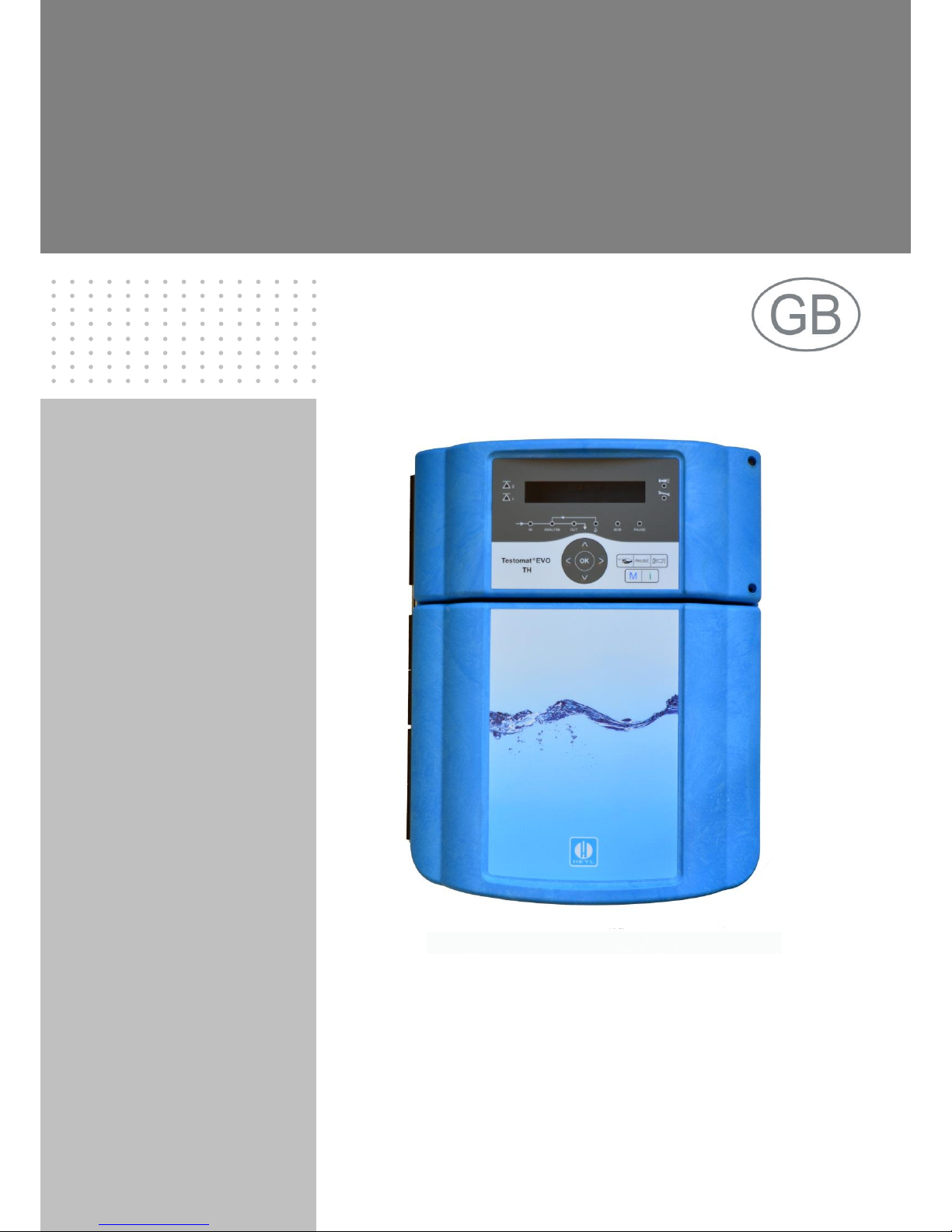
Testomat® EVO TH
Online analysis instrument
for residual total hardness
(water hardness)
Operating Instructions
Page 2

Content
2
Content
Content ................................................................................................. 2
Important safety information ............................................................. 5
Intended use .................................................................................... 5
Qualification of personnel ................................................................ 5
Warnings in this manual .................................................................. 6
Additional documentation ................................................................ 6
Special attention is required at this point .............................................. 6
General Information ......................................................................... 6
Requirements for the installation site............................................... 6
Requirements of cable for mains voltage and system components
and installed lines ............................................................................ 7
Requirements for cable ducts .......................................................... 7
During assembly .............................................................................. 8
During operation .............................................................................. 8
During cleaning ................................................................................ 9
Malfunctions/repairing a defective device ........................................ 9
During disposal ................................................................................ 9
Operating requirements ................................................................. 10
Delivery includes: ............................................................................. 11
Service description ........................................................................... 11
Available indicators for Testomat® EVO TH devices .......................... 12
Assembly ........................................................................................... 13
Assembling the Testomat® EVO TH ................................................... 13
Use of the Testomat® EVO TH within a pressure range of 0.3 to 1 bar13
Connecting the water intake and discharge ........................................ 14
Water intake ................................................................................... 14
Water drain .................................................................................... 15
Connect mains and devices ................................................................ 15
Block diagram of Testomat® EVO TH ............................................ 16
Internal structure of Testomat® EVO TH ............................................. 17
Cable ducting ................................................................................. 18
Install power supply board and connect mains voltage ................. 18
Connect system components ........................................................ 19
Connect inputs and outputs ........................................................... 21
RS232 interface terminal assignment ............................................ 22
Connect indicator bottle ................................................................... 23
Insert indicator bottle ..................................................................... 23
Open water intake .......................................................................... 23
Device settings and data input ....................................................... 24
Functions of the control and display elements ............................. 24
Switching the Testomat® EVO TH device on/off ............................ 24
Display functions ............................................................................ 25
Control and function keys .............................................................. 26
Operating system ........................................................................... 27
Control elements on the control board........................................... 30
Mounting the SD card .................................................................... 30
Status displays of the SD card ....................................................... 30
Getting started .................................................................................. 31
Input basic programming data ........................................................ 32
Select operating mode ........................................................................ 32
Select timing control....................................................................... 32
Page 3

Content
3
Select quantity control ................................................................... 32
Select quantity control/time priority ................................................ 33
Configure interval (interval pause) ...................................................... 33
Select indicator type and container size ............................................. 34
Select measurement value unit........................................................... 34
Limit value monitoring ......................................................................... 35
Input operating mode of LV1 and LV2 limit value outputs ............. 35
Switching functions of the LV1 and LV2 limit value outputs .......... 36
Input purge cycle ................................................................................. 37
Select water meter .............................................................................. 38
BOB operation (operation without constant supervision) ................... 38
Description of the relay outputs .......................................................... 39
LV1 and LV2 limit value outputs .................................................... 39
AUX (programmable functional output) ......................................... 40
Alarm (Fault signal output) ............................................................. 40
Alarm/message – How to proceed when errors occur ........................ 41
Water shortage ................................................................................... 42
Error history......................................................................................... 42
Description of the signal inputs/outputs .............................................. 43
Stop input ....................................................................................... 43
External delete (external acknowledge) ........................................ 44
Input water meter ........................................................................... 44
Current loop 0/4 - 20 mA ..................................................................... 44
Calculation of output currents ........................................................ 45
Serial interface .................................................................................... 46
Notification format .......................................................................... 46
LCD settings........................................................................................ 47
Description of the SD card functions .................................................. 47
Storing measurement values ......................................................... 48
Store error ...................................................................................... 48
Interim storage for a non-inserted SD card ................................... 49
Capacity of the SD card ................................................................. 49
Export basic programming data ..................................................... 49
Import basic programming data ..................................................... 50
Password protection ........................................................................... 50
Password input .............................................................................. 50
Change password .......................................................................... 51
Password protection ........................................................................... 51
Firmware update ................................................................................. 51
Menu-driven firmware update ........................................................ 51
Manual firmware update ................................................................ 53
Maintenance........................................................................................ 53
Configuring the maintenance interval ............................................ 53
Acknowledge the maintenance ...................................................... 53
Information menu "i" ........................................................................ 54
Service menu ..................................................................................... 55
Structure of basic programming ..................................................... 57
Error messages/troubleshooting .................................................... 58
Further possible errors ........................................................................ 61
Error messages after self-test ............................................................. 61
Firmware update error list ................................................................... 63
Servicing and maintenance ............................................................. 66
Page 4

Content
4
Description of the maintenance work .................................................. 66
Replacing indicator ........................................................................ 66
Setting indicator fill level ................................................................ 67
Cleaning of the measuring chamber and the viewing windows ..... 67
Cleaning the filter housing ............................................................. 67
Care instructions ................................................................................. 68
Replacing the backup battery ............................................................. 68
Replacing fuses .................................................................................. 69
Checklist Testomat® EVO TH ............................................................. 73
Spare parts and accessories for Testomat® EVO TH .................... 75
Accessory ............................................................................................ 76
Technical Data ................................................................................... 77
Equipment options .............................................................................. 78
Declaration of conformity .................................................................... 79
NRTL certificate .................................................................................. 80
TÜV certificate..................................................................................... 81
Page 5
Important safety information
5
Important safety information
Read the operating instructions carefully and in full before working
with the device.
Ensure that the operating instructions are accessible at any time for
all users. When an SD is used in the device, it can also be stored on
the same as a PDF file.
If transferring the Testomat® EVO TH device to third parties, ensure
these operating instructions are always included.
Observe the safety precautions and safety recommendations when
using reagents, chemicals and cleaning agents. Observe the relevant
safety data sheet! For reagents we supply, the relevant safety data
sheets are available online at http://www.heyl.de.
Intended use
The scope of use of the Testomat® EVO TH is the automatic determination and monitoring of the residual total hardness (water hardness)
in water. In the process, the required measurement scope is determined based on the selected indicator and corresponding user programming.
Comply with the output limits specified in the "Technical Data" section.
Observe the areas/limits of application of the indicators and the requirements imposed by the medium to be measured.
The scope of intended use presumes that you have read and understood the instructions and particularly the section on "Important safety
information".
Improper use is deemed to occur if you use the device
outside the applicable scope, as specified in these instructions,
under operating conditions that deviate from the scope specified in
these instructions.
Qualification of personnel
The assembly and commissioning require basic electrical and process engineering expertise as well as knowledge of the applicable
specialist terms. The assembly and commissioning must therefore be
performed only by a specialist or a properly trained person instructed
and supervised by a specialist.
A specialist is a person who can draw on professional training,
knowledge and experience as well as knowledge of applicable provisions to assess work assigned to him/her, detect potential hazards
and implement suitable safety measures. A specialist must comply
with the applicable professional rules.
Page 6
Important safety information
6
Warnings in this manual
These instructions include warnings against specified actions that
involve the risk of injury or property damage. Warnings are structured
as follows:
Description of the type or source of danger
Description of the consequences of non-compliance
Hazard prevention indications. Compliance with these hazard preven-
tion measures is imperative.
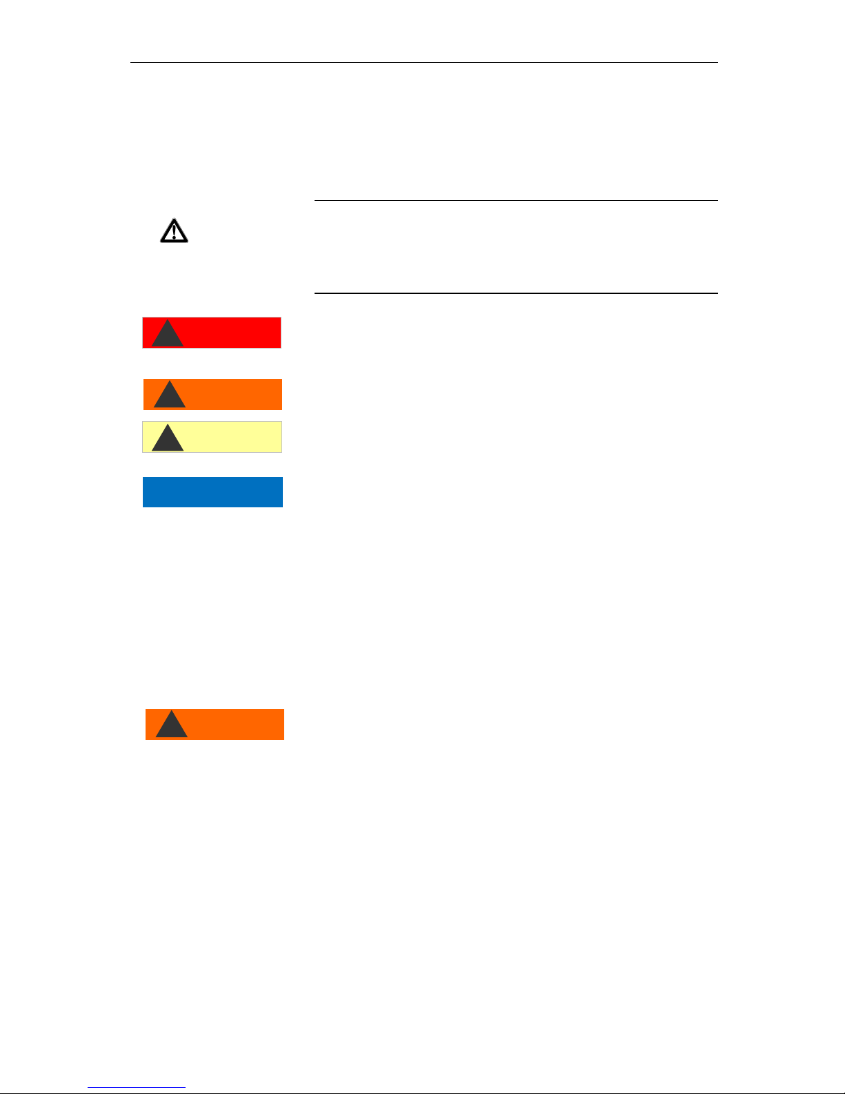
The signal word "RISK" refers to a significant danger that represents
a direct threat and will definitely result in severe injuries or even be
fatal if not avoided.
The signal word “WARNING" refers to a possible danger that may
result in severe injuries or even be fatal if not avoided.
The signal word "CAUTION" refers to a potentially dangerous situation that could result in minor to moderate injuries or property damage if not avoided.
The signal word "NOTE" refers to important pieces of information. If
this information is not heeded, it may adversely affect operational
procedures.
Additional documentation
The Testomat® EVO TH device is a system component. Accordingly,
you should also observe the Testomat® EVO TH maintenance manual and the system documentation of the system manufacturer.
Special attention is required at this point
General Information
During assembly and commissioning, observe the specific national
and local requirements.
Observe the accident prevention and conservation requirements in
the country of use and at the installation site.
Make no changes or modifications to the device that go beyond the
scope of use specified in these instructions. Doing so will void the
warranty.
Requirements for the installation site
Ensure that the following conditions are met at the installation site:
Use the device in indoor locations only.
The ambient temperature is between 10 and 40°C.
The installation site is at altitudes under 2000 m.
The maximum relative humidity is 80% at temperatures of up to
31°C (linear declining up to 50% relative humidity at 40°C).
SIGNAL WORD!
WARNING
!
CAUTION
!
DANGER
!
NOTE
WARNING
!
Page 7

Important safety information
7
The device must always be protected against wetness and mois-
ture. Under no circumstances may it be exposed to splashed water
or condensate.
Surge category II
Soiling degree II
Requirements of cable for mains voltage and system components and installed lines
Use only cables and installed lines which meet the following requirements:
Dielectric strength 30 V … 260 V according to the nominal voltage
(see specification plate)
The cable ducts installed by Gebr. Heyl in the device have a
clamping range of 4.5 mm – 10 mm. This means that the external
diameter of the laid cable must remain within the range of 4.5 mm
– 10 mm. If you use other ducts, the cable diameters must correspond to the ducts.
The terminal strips on the circuit board require core cross-sections
of between 0.08 mm2 and 2.5 mm2. This applies to single-wire and
fine-wire cores with wire end ferrules without plastic collar.
For fine-wire cores with wire end ferrules and plastic collar, the
cross-section may be up to 1.5 mm2.
For single-wire cores, AWG28 – AWG12 can also be used.
Optimum cross-section of the cores
If the core cross-section is less than 0.5 mm2, jamming may occur
when the cores are loosened from the terminal strip. We therefore
recommend using wires with cross-sections greater than 0.5 mm2.
Requirements for cable ducts
The recesses in the housing are intended for M16 ducts.
The ducts should have a smooth and rounded opening (to protect
against bending and abrasion).
Be careful to ensure securely fastened bending protection, which
must be five times the length of the maximum cable diameter.
The duct should include a strain relief that prevents slippage of the
cable and that cannot be disengaged without a tool.
You can order cable ducts from us as spare parts (Spare parts and
accessories).
If you use another cable duct, the material must have a flammability rating of V1 or better.
NOTE
Page 8
Important safety information
8
During assembly
Always disconnect the relevant system component from the power
source before assembling the device or connecting it to the power
supply or disconnecting it from the same. Prevent any inadvertent
reactivation of the device.
Only connect the device to the mains voltage as specified on the
type plate.
Observe the technical data and the environmental parameters.
The connections for mains voltage and relay outputs must be laid
separately from each other, to guarantee corresponding insulation
between the cables. Accordingly, do not operate the device if the
partition walls or terminal area covers are not present.
Avoiding interference voltages
The Testomat® EVO TH device requires stable and uninterrupted
supply voltage. Where applicable, use a mains filter to shield the
Testomat® EVO TH device from interference voltages, which may be
generated for example within the network by magnetic valves or
large-scale engines. Never lay the connecting cables in parallel to
mains cables.
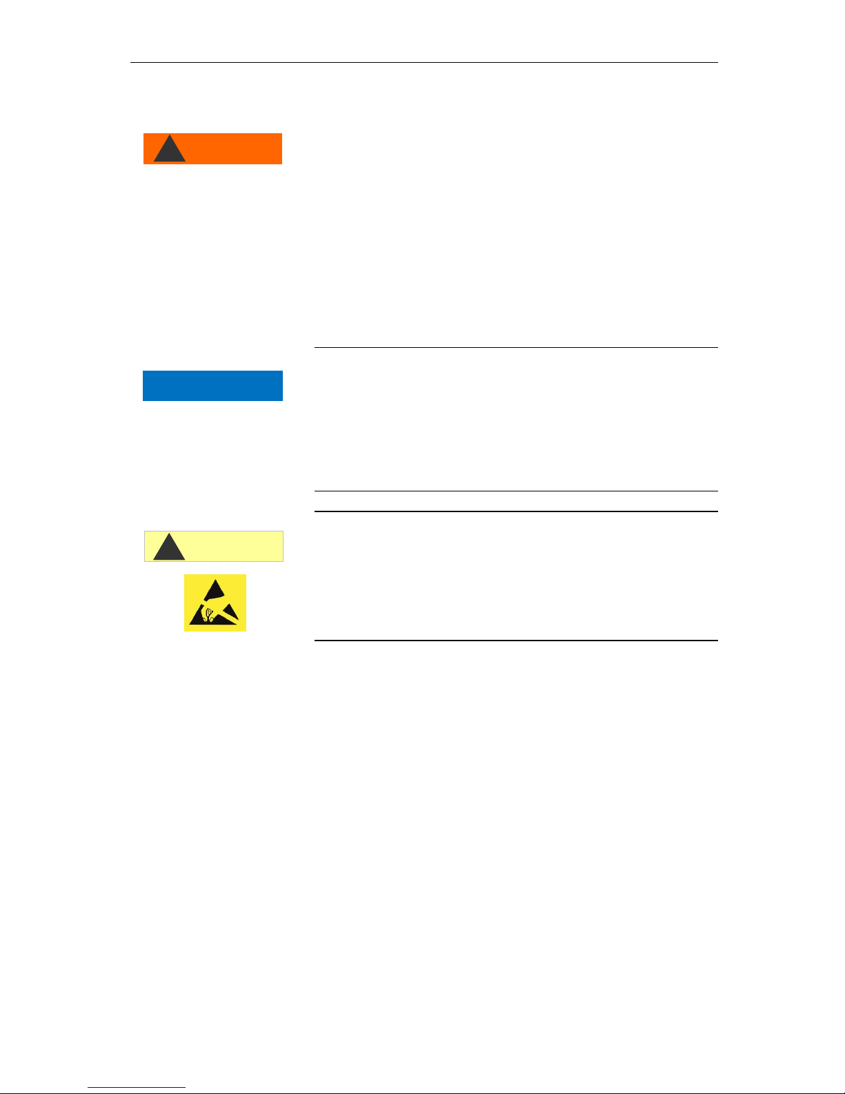
Handling may cause damage or destruction of electrical components!
If you need to open the upper door, you should take the necessary
safety measures to avoid electrostatic discharge onto the components (ESD safety).
Make sure you are earthed before opening the casing.
During operation
The device has no power switch.
Use an external power switch to turn the unit on and off. The
switch must be installed next to the device and must be marked as
power switch for the device - for example with a label.
Ensure that the maximum electrical load capacity of the switching
outputs is not exceeded, particularly for inductive loads. The power
supply for the user inclusive device is secured with a 4A fuse,
which means the total of all loads must not reach 4A.
In the event of any malfunctions, immediately switch off the Tes-
tomat® EVO TH device and inform the service personnel. Never attemt to repair the Testomat® EVO TH device yourself. Doing do will
invalidate the guarantee. Repairs must be performed by authorized
service personnel only.
WARNING
!
NOTE
ATTENTION
!
Page 9

Important safety information
9
During cleaning
Only use a dry and lint-free cloth.
Maintenance and care instructions are included in the section
"Servicing and maintenance” and in the Testomat® EVO TH
maintenance manual
Malfunctions/repairing a defective device
A defective device, regardless of the guarantee period, can be
serviced only when the device is dismantled and the error is described. Please also inform us of the indicator type currently in use
and the measured medium. Make no changes or modifications to
the device that go beyond the scope of use specified in these instructions. Doing so will void the warranty. This applies particularly
to the measuring chamber, the seal of which must remain undamaged. If you send the device in for repair, please completely empty
the measuring chamber and remove the indicator bottle and the
drain funnel. Also remove the power pack and send it back in the
original packaging.
Before dismantling, the type of error must be noted (error number,
error effect, log file of the SD card).
Once a protective device has been triggered (safety fuse), initially
try resolving the cause of error (e.g. by replacing a defective
valve), before reactivating the protective device. Frequent triggering always signifies an error, which under certain circumstances
may also damage the device.
Before sending the device in for maintenance or repair, pack-
age the power pack individually in the original box in which it
was delivered. If the original packaging is no longer available,
package the power pack to prevent breakage.
During disposal
Dispose of the device in accordance with the regulations of your
country.
Page 10

Important safety information
10
Operating requirements
Problem-free operation of the Testomat
®
device is only possible
when using Heyl Testomat indicators and only within the pH range
of 4 – 10.5! Using external indicators may invalidate the guarantee.
Only operate the device within the scope of parameters specified
under "Technical Data".
For Testomat® devices used to monitor water hardness, large
quantities of heavy metal ions in the hardened water may disturb
the color reaction, particularly
o Iron over 0.5 mg/I
o Copper over 0.1 mg/I
o Aluminum over 0.1 mg/l (brown-red color indication).
If the test water contains more than 20 mg/I CO2 (carbonic acid),
erroneous evaluations cannot be ruled out. In this case, use an irrigator (e.g. optional accessory from Heyl Co.).
The water to be measured must be clean and free of bubbles!
The concentrations of disruptive ingredients can be determined
with colorimetric TESTOVAL® test comparators from Heyl Co.
In the event of
o excessive carbonate hardness
o the presence of disinfecting agents
o the presence of silicate (used to protect pipes), the measur-
ing chamber may become soiled, which over time
may lead to erroneous evaluations
Careful handling of the device enhances the operational safety and
the service life! With this in mind, perform a visual inspection of the
device at regular intervals as follows:
o Has the expiry date of the indicator elapsed?
o Are the hose connections of the dosing pump leakproof?
o Is there any air in the dosing hoses?
o Are all water connections leakproof?
o Is the door of the device carefully closed?
o Is the device excessively soiled?
o Are the measuring chamber and drain channel/drain hose
clean?
Problem-free operation is contingent on regular maintenance!
Maintenance and care instructions can be found in the "Servicing
and maintenance" section.
Indications of problems can be found in the "Error messag-
es/troubleshooting" section.
CAUTION
!
NOTE
Page 11

Delivery includes:
11
Delivery includes:
1 Testomat® EVO TH
1 plastic bag with:
- Screw cap including hole and an insert for the screw cap of
the indicator bottle
1 package with:
- 1 plastic bag with
• Drain funnel
• 2 screws for mounting power supply unit
- Power supply
1 User manual
Attention!
Depending on your order, you may have a device with blue or black
housing. The operating instructions apply to both colours, as the
functionality is the same.
Service description
The scope of use of the Testomat® EVO TH is the automatic determination and monitoring of the residual total hardness (water hardness)
in water. In the process, the required measurement scope is determined based on the selected indicator and corresponding user programming.
Simplified menu-driven operation and programming via backlit
graphic LCD.
Based on the selected indicator, determinable measurement of
overall hardness (water hardness)
Free selection of hardness units in °dH, °f, ppm CaCO3, or mmol/l
Highly accurate measurement thanks to the use of precise piston-
dosing pump
Extended operating periods due to 500 ml indicator storage bottle
Analysis trigger:
– Automatic interval operation
(Interval pause can be configured from 0-99 minutes)
– Depending on quantity, via contact water meter
– External disruption of analysis
Two independent limit values with adjustable switching functions
as well as switching option in accordance with an adjustable number of negative analyses (Two neutral change-over contacts)
Logging on SD card for measurement data and notifications/alarms
with interim buffer for 100 measurement values and 50 notifications.
Import and Export of settings (basic program data) with selectable
filenames.
NOTE
Page 12
Service description
12
Error history for 20 notifications
Firmware update via SD card
Built-in self-test with ongoing monitoring
Optional wireless retrieval of data with special WLAN SD card
Features for integration into process controllers:
– Fault signal output (neutral changeover contact) with Clear
input
– Current loop 0/4 - 20 mA for analog transfer of measurement
data
– Serial RS232 interface to transfer measurement data and no-
tifications/alarms
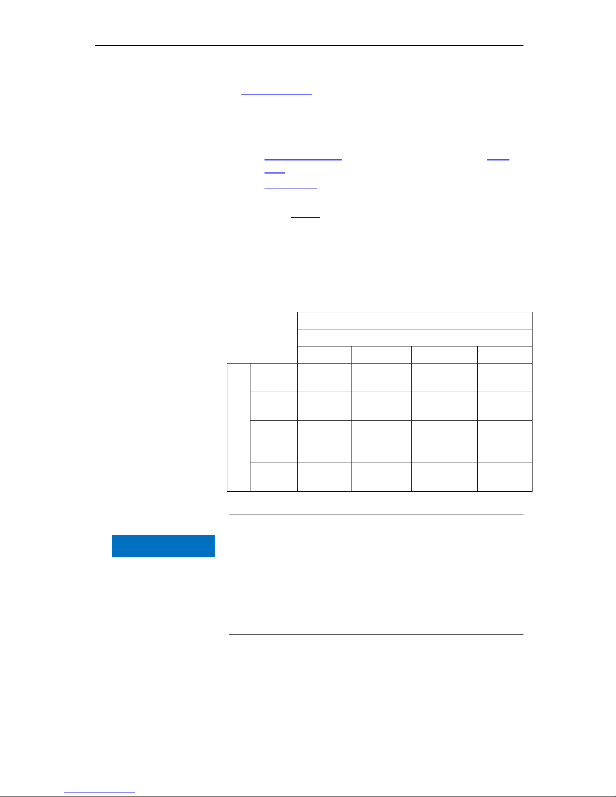
Available indicators for Testomat® EVO TH
devices
Parameter/indicator type
Water hardness
TH 2005
TH 2025
TH 2100
TH 2250
Unit
°dH
(resolution)
0.05 - 0.50
(0.01)
0.25 - 2.50
(0.05)
1.0 - 10.0
(0.2)
2.5 - 25.0
(0.5)
°f
(resolution)
0.09 - 0.89
(0.02)
0.45 - 4.48
(0.1)
1.8 - 17.9
(0.4)
4.5 - 44.8
(1.0)
[ppm]
CaCO
3
(resolution)
0.89 - 8.93
(0.2)
4.5 - 44.8
(0.9)
18 - 179
(3.8)
45 - 448
(10)
mmol/l
(resolution)
0.01 - 0.09
(0.01)
0.04 - 0.45
(0.01)
0.18 - 1.79
(0.04)
0.45 - 4.48
(0.1)
Please be careful to ensure that Heyl indicators are used!
Using external indicators may result in considerable measurement
deviations or measurement errors. Damage caused by foreign particles in the area of the dosing pump, measuring chamber or valves is
also possible. This may invalidate the guarantee!
At Heyl, we always strive to ensure the consistently high quality of
our indicators. They are specially tailored to the requirements of our
measuring devices and guarantee flawless measurement results.
NOTE
Page 13
Assembly
13
Assembly
Hazard due to defective assembly!
Assemble the Testomat® EVO TH device in a location shielded
from drips and splashes of water, dust and aggressive substances
– e.g. in a switching cabinet or on a suitable wall.
Notes for problem-free operating procedures
Assemble the Testomat® EVO TH device vertically and without
mechanical stresses.
Assemble the Testomat® EVO TH device in a location free of vibra-
tion.
Assembling the Testomat® EVO TH
Requirements for the installation site
Select an installation site at which the length of the water inlet hose
can be minimized (max. 5 m)
Leave sufficient room on the left side of the device to open the
door.
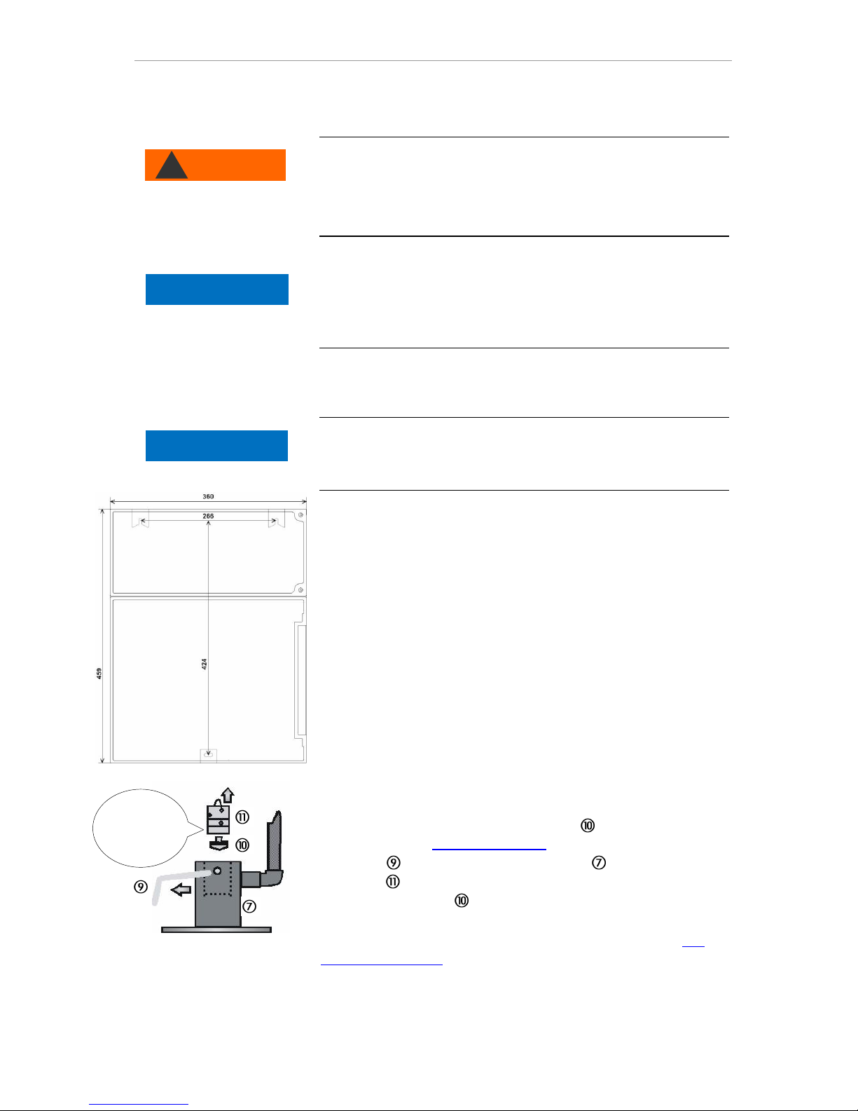
Drill the mounting holes as specified in the accompanying sketch-
es.
Secure the device with three screws in a suitable place in the
switching cabinet or on the wall.
Use of the Testomat® EVO TH within a pressure range of 0.3 to 1 bar
Before assembling please check whether adaptation to a lower working pressure is required. When delivered, the device is equipped for a
pressure range of 1 to 8 bar. To operate the device within a pressure
range of 0.3 to 1 bar, the flow governor core should be removed
(e.g. when using a type R mini irrigator). For this purpose, take the
locking pin from the controller/filter housing . Then pull the controller plug on the metal brackets out of the drill hole. Then remove
the flow governor core and re-insert the controller plug and locking
pin.
At pressures under 0.3 bar or when sucking out of a tank, our Me-
puClip booster pump can be used.
Remove for a
pressure
range of 0.3
to 1 bar
WARNING
!
NOTE
NOTE
Page 14
Assembly
14
Connecting the water intake and discharge
When using a cooler
Water exceeding 40°C may lead to burns and may damage the
parts of the Testomat® EVO TH exposed to the water.
Notes for problem-free operating procedures
The water pressure must be within the range 0.3 to 8 bar.
To operate within a pressure range of 0.3 to 1 bar or when supply-
ing via a booster pump, please remove the controller core from the
controller and filter housing. The pump should have a capacity of
25 to 35 liters/hour and be correspondingly resistant to the medium
being measured (e.g. our booster pump MepuClip Art. No. 270410)
For operation exceeding 8 bar, a pressure reducer must be used.
Significant pressure fluctuations should be avoided
The measurement water temperature must be between 10 and
40°C
For water temperatures exceeding 40°C, a cooler must be installed
in the intake of the Testomat® EVO TH.
We recommend short intake lines (under 3m) to the Testomat®
EVO TH. For intake lines longer than 3m, purge periods of longer
than 60s must be configured. For cable lengths exceeding 5 - 10m,
we recommend external flushing via the AUX input.
Water intake
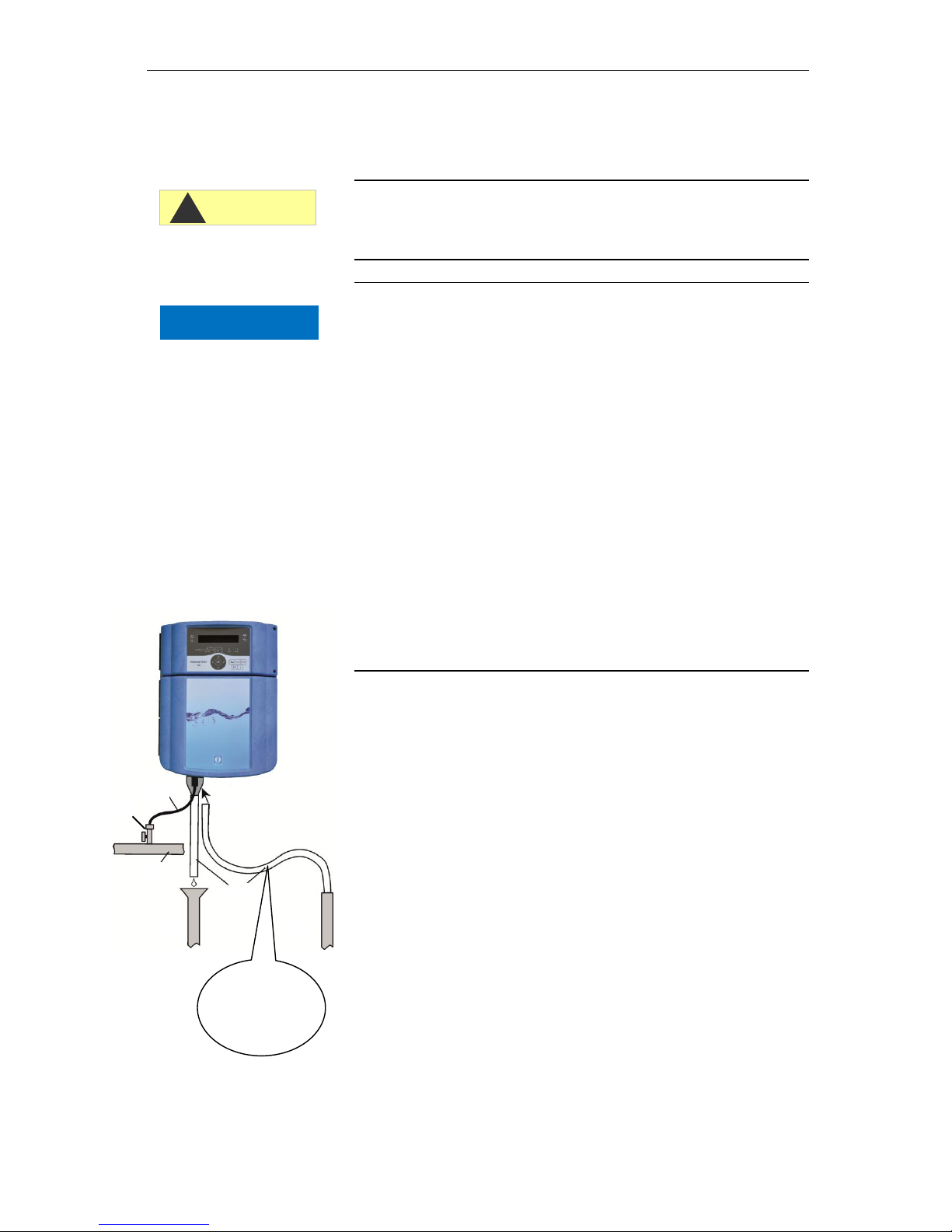
The test water is extracted from the sampling pipe and channeled to
the supply nozzles of the Testomat® EVO TH. The device comes with
a plug connection for plastic hoses 6/4 x 1 as standard (external diameter 6 mm/ internal diameter 4 mm, wall thickness 1 mm).
Connect the linking piece for the intake of the Testomat® EVO TH
directly to the sampling pipe directly behind the water treatment
plant
Always establish the connection vertically upwards, to prevent dirt
particles from being conveyed from the sampling pipe to the device
Assemble a manual stop valve in the intake to the Testomat® EVO
TH
For the water intake use opaque plastic pressure hose 6/4 x 1
(max. length 5 m)
Purge the intake to remove dirt particles
NO !!
"Sagging"
causes back-
water!
NOTE
CAUTION
!
Page 15
Assembly
15
Water drain
The water is conveyed through the measuring chamber via an open
funnel and the drain hose installed on the same and into the duct.
Remove the supplied funnel and accommodate it underneath, in
the recess of the housing designated for that purpose.
Connect the funnel of the Testomat
®
EVO TH with a drain hose
(internal diameter 12 mm/14 mm)
Lay this hose free of back pressure and without the siphon effect
to the drain
Connect mains and devices
Risk of injury from assembly when voltage present!
Unless you disconnect the power supply before commencing assembly, you risk injury, destruction of the product or damage to system
components.
Disconnect all power to the relevant system component before
assembling the Testomat® EVO TH device.
When connecting, use only verified cables with sufficient line
cross-section.
Disconnecting device for the power supply
The unit has no power switch!
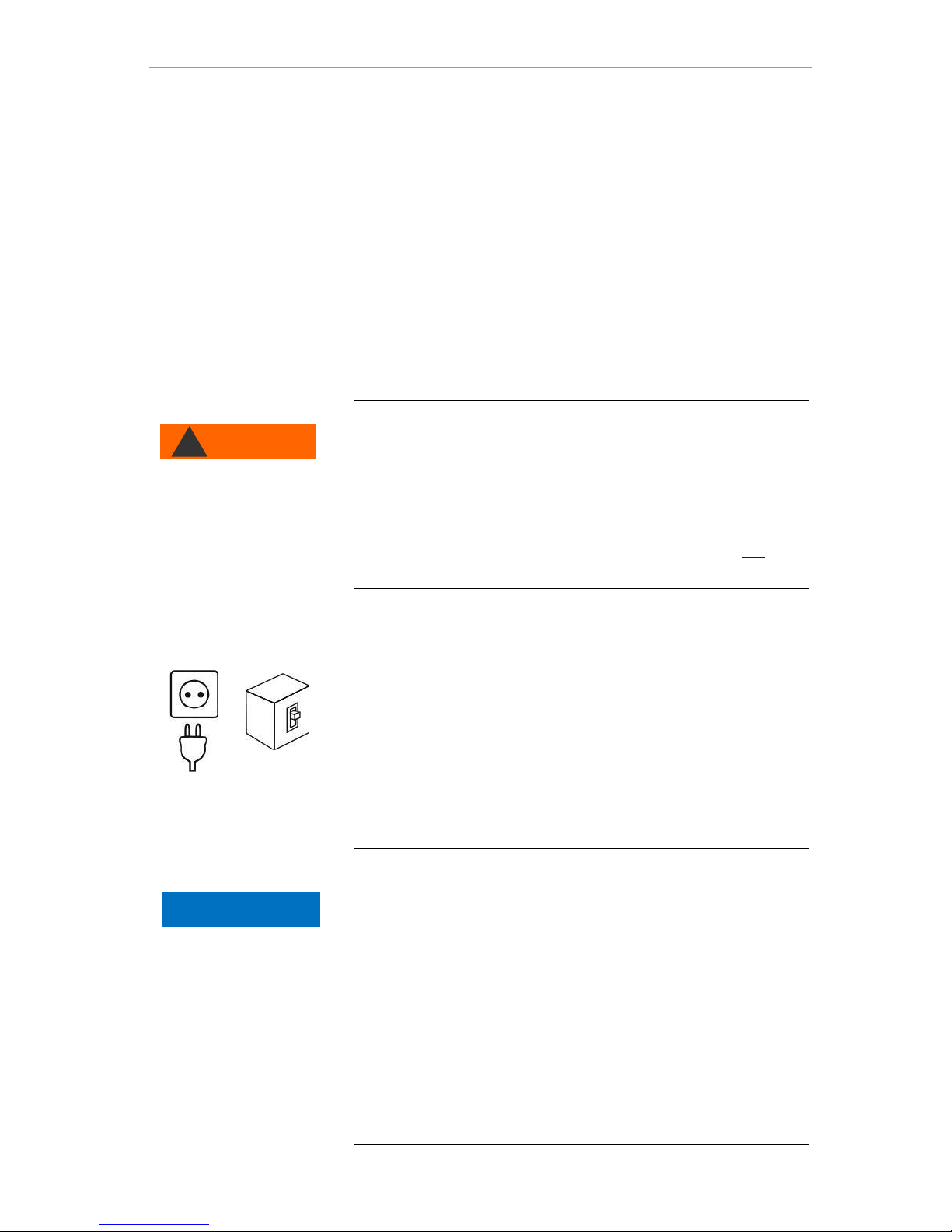
Fit the Testomat® EVO TH with a switch as a disconnecting device for
the power supply. Use an appliance switch or a circuit breaker that
meets the requirements of IEC 608947-1 and IEC 60947-3.
The switch must be within easy reach of the user of the Testomat®
EVO TH and clearly marked as a disconnecting device for the Testomat® EVO TH.
For disconnection, you can also provide a three-pin plug near the
device, which is clearly marked as a disconnecting device for the
Testomat® EVO TH CAL.
Danger of damage due to electromagnetic fields!
If you assemble the Testomat® EVO TH device or connecting ca-
bles parallel to mains cables or in the vicinity of strong electromagnetic fields, the device may be damaged or the measurement disrupted.
Keep the connecting cables as short as possible
Lay the connecting cables and mains cables separately.
Connect the device with the protective conductor (at 230/100-240
VAC).
Keep interference voltages away from the Testomat® EVO TH
device – e.g. by using a mains filter.
Shield the device from strong electromagnetic fields.
WARNING
!
NOTE
Page 16
Assembly
16
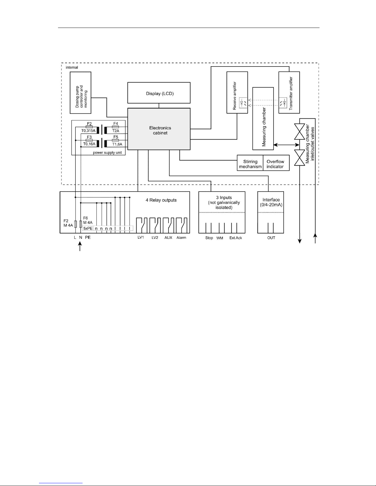
Block diagram of Testomat® EVO TH
Illustrated position of relays: Device without current, mains: 230 V
Page 17
Assembly
17
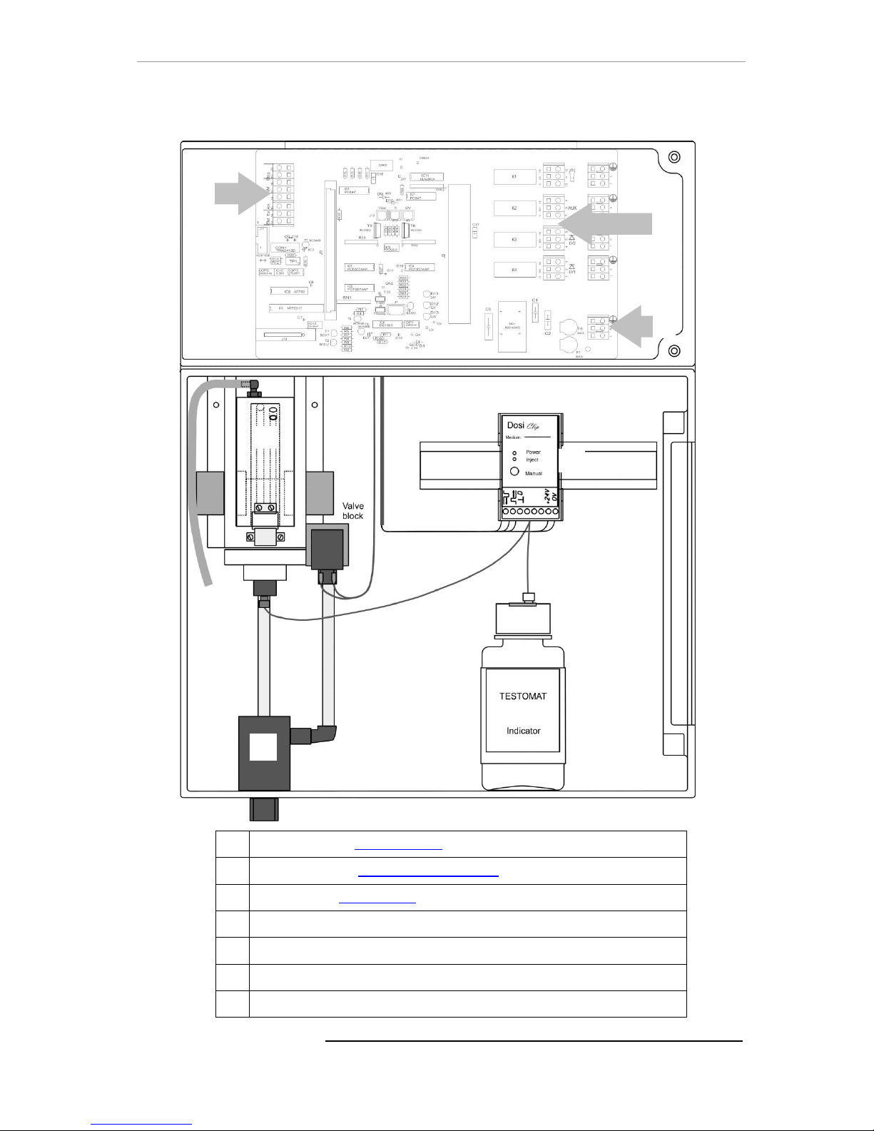
Internal structure of Testomat® EVO TH
Terminal strip for inputs/outputs
Terminal strip for mains inlets and outlets
Terminal strip relay outputs
Dosing pump
Water connections, intake and outlet (funnel)
Controller/filter housing
Measuring chamber
Page 18
Assembly
18
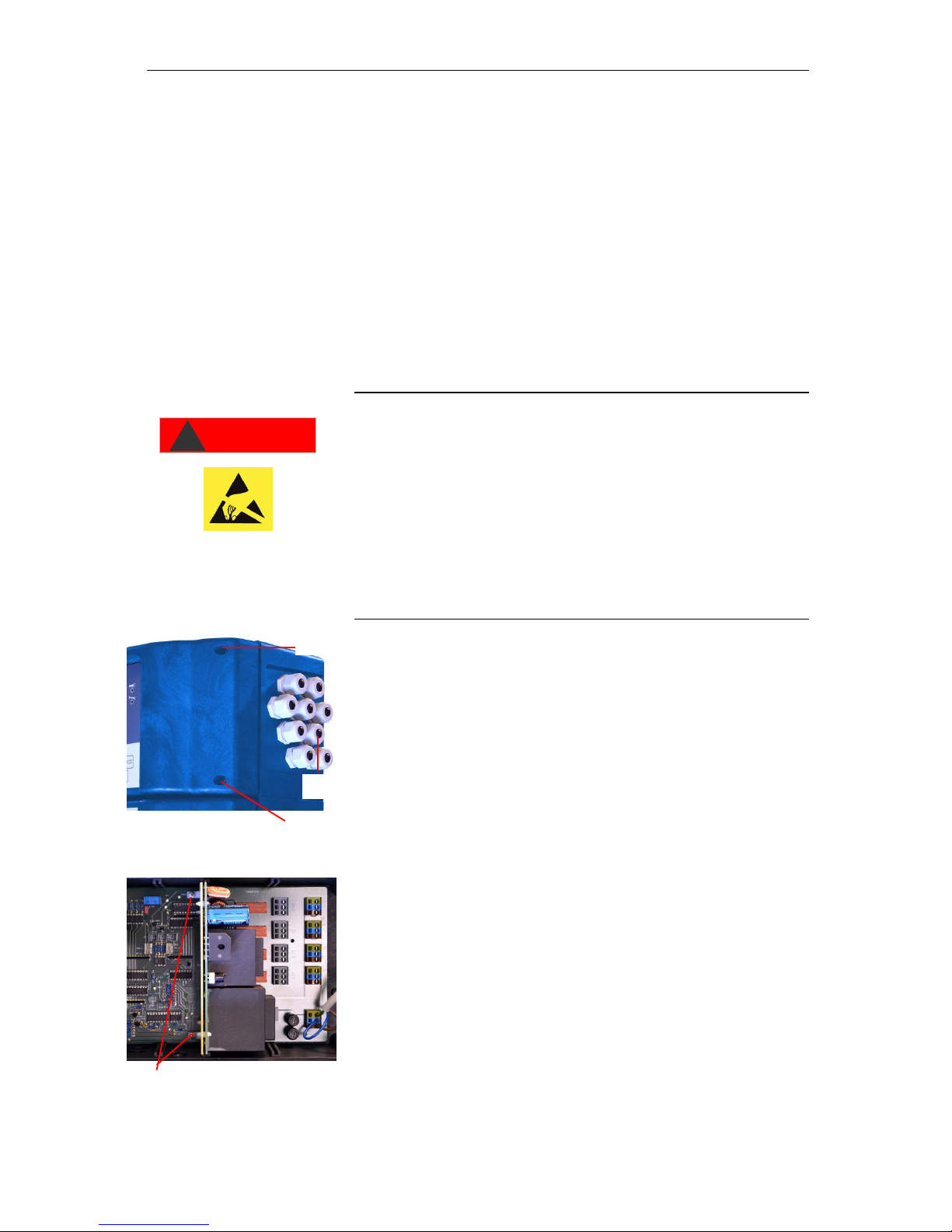
Cable ducting
To guarantee IP protection, the device is supplied with cable ductings
and blanking plugs. If you wish to use a relay output, you must remove the blanking plug from the cable ducting.
Proceed as follows in this instance:
Loosen the strain relief of the cable ducting (union nut).
Take out the blanking plug and insert the cable.
Tighten the union nut of the cable ducting and so establish the
strain relief.
Install power supply board and connect mains
voltage
Installing the terminal compartment cover
For technical safety reasons, the terminal compartment cover must
be put back in place immediately after connecting the mains voltage
and the system components, since the terminal space houses cables
that carry dangerous voltages. This helps prevent inadvertent contact
with the terminals and contact between the individual lines that may
carry different voltages and thus avoid the risk of a life-threatening
electric shock.
Also ensure that the cables are not pinched when installing the
terminal compartment cover!
Connect the device only to the mains voltage for which it is designed.
See type plate to confirm the suitable mains voltage. To connect the
cable, please proceed as described below:
Remove both fixing screws and open the upper door.
Remove the power supply board from the box at the bottom of the
housing.
Insert the power supply board into the slot on the mainboard.
Screw in the two fastening screws at the top and bottom of the
mainboard.
Remove the fixing screws of the terminal cover and then remove
the terminal cover itself.
Lay the cable through the cable ducting provided for that purpose.
Tighten the union nut of the cable ducting and so establish the
strain relief.
Connect the supply voltage to the terminals PE,N,L or, for 24 V
devices, to U and V terminals.
Ensure that the cores in the terminals are securely in place.
Install the terminal compartment cover.
DANGER
!
Observe ESD safety
precautions! See the
information on page 8
Page 19
Assembly
19
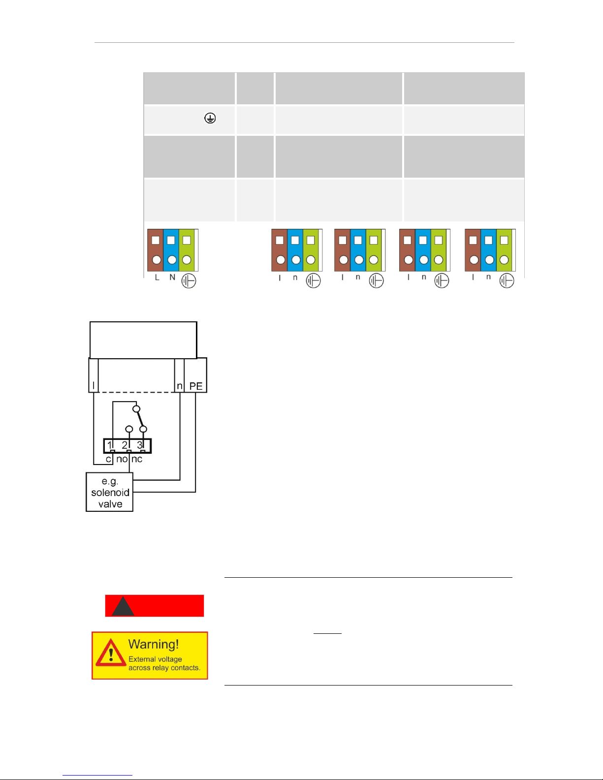
Terminal designation
Type
Function
Note
Mass/PE
IN
Mains protective conductor
(5x)
Only for mains supply of
230 V and 100 – 240V!
N (U)
L (V)
IN
Grid, N=Neutral conductor
(U=24V)
Grid, L=Phase (V=24V)
Power input 50-60 Hz
24 V / 100-240 V / 230 V
n
l
OUT
Neutral conductor, secured
with 4A (4x)
Phase, secured with 4A (4x)
Grid for consumers, max. 4
A
Connect system components
Take out the blanking plugs of the corresponding cable ductings.
Push through the cable of the component.
Tighten the union nut of the cable ducting and so establish the
strain relief.
Connect the system components to the output terminals of relays 1
to 4 (e.g. valves)
If the system components require mains power, connect the exter-
nal switched mains voltage (l) to the root contact of the respec-
tive relay (see accompanying connection example for 230 VAC)
Connect the neutral conductor of the system component with one
of the terminals (n)
For components with a protective conductor connection, connect
them to the PE connection.
Ensure that the cores in the terminals are securely in place
(Illustrated position of relays: Device without current, mains: 230 V)
Indicate external voltage on the relay contacts!
If you connect system components that do not operate using the device voltage, you can apply external voltages to the relay contacts.
This external voltage cannot be switched off via the external mains
switch.
There is a danger of electric shock!
Affix a warning to the device in this case (e.g. a sticker as shown left).
Connection example
Limit value contact LV 1
switches mains voltage
DANGER
!
Page 20
Assembly
20
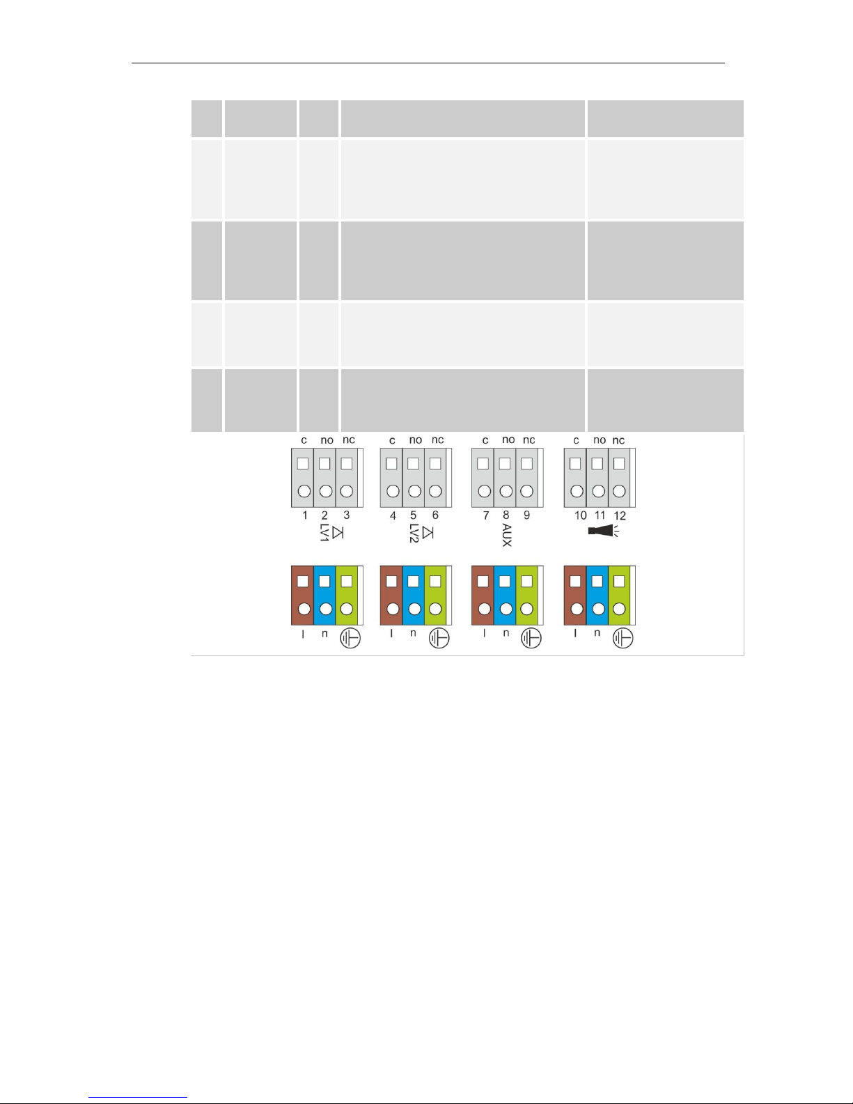
No.
Terminal
designation
Type
Function
Note
1
2
3
LV1
(limit value)
OUT
Limit value output 1 – root c
Limit value output 1 – closing contact
NO
Limit value output 1 – break contact NC
Floating relay output,
max. 240 VAC, 4 A
4
5
6
LV2
(limit value)
OUT
Limit value output 2 – root c
Limit value output 2 – closing contact
NO
Limit value output 2 – break contact NC
Floating relay output,
max. 240 VAC, 4 A
7
8
9
AUX
(auxiliaries)
OUT
Function output – root c
Function output – closing contact NO
Function output – break contact NC
Floating relay output,
max. 240 VAC, 4 A
10
11
12
Alarm
OUT
Fault signal output – root c
Fault signal output – closing contact NO
Fault signal output – break contact NC
Floating relay output,
max. 240 VAC, 4 A
Page 21
Assembly
21
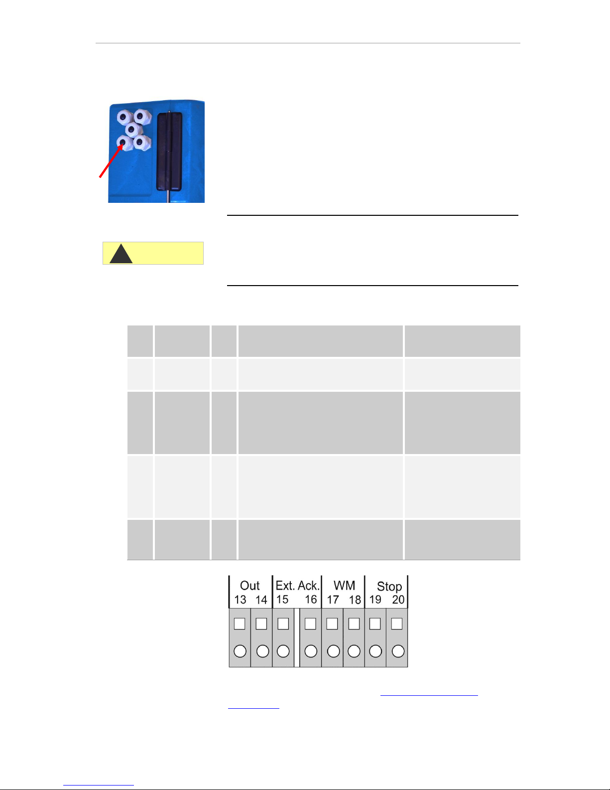
Connect inputs and outputs
The Testomat® EVO TH device has the following sockets for control
and monitoring functions. Proceed as follows for connection:
Loosen the strain relief of the cable ducting (union nut).
Take out the blanking plugs of the corresponding cable ductings.
Push through the cable of the component.
Tighten the union nut of the cable ducting and so establish the
strain relief.
Re-secure the upper door after installation with both fixing screws.
Correct connection of the inputs and outputs
Do not expose the connections to any external voltage!
Ensure that the cores in the terminals are securely in place
Incorrect connections will damage the device!
A detailed description is included in "Description of signal in-
puts/outputs".
No.
Terminal
designation
Typ
e
Function
Note
13
14
Out +
Out -
OUT
Current loop 0/4 - 20 mA
Galvanically isolated
15
16
Ext. Ack.
(external
acknowledge
)
IN
External reset / acknowledgment input
port for error and alarms
Break contact/closing
contact programmable;
only connect isolated
break contact/closing
contact
17
18
WM
(watermeter)
IN
Water meter intake
Common ground for inputs
Only connect isolated
break contact/closing
contact or observe the
technical data of the meter!
19
20
Stop
IN
External disruption of analysis
Common ground for inputs
Only connect isolated
break contacts/closing
contacts!
CAUTION
!
Page 22
Assembly
22
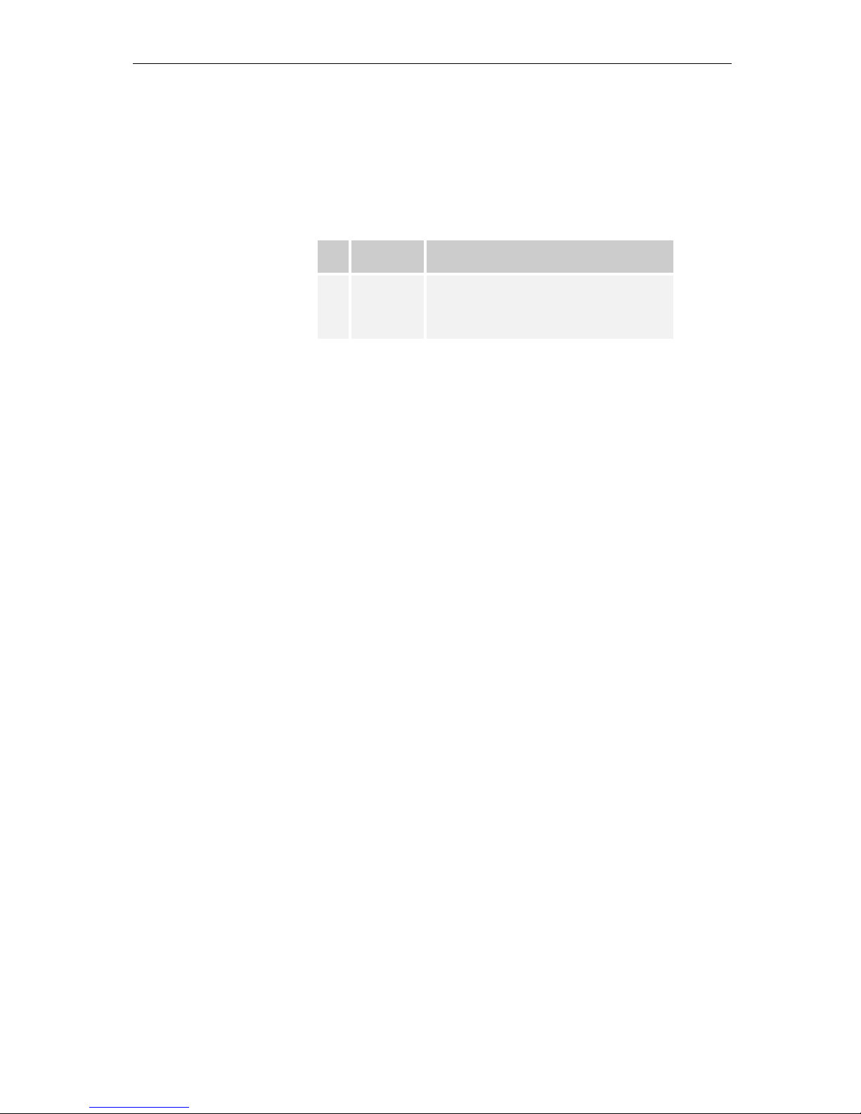
RS232 interface terminal assignment
1 2 3 4 5
O O O O O
Sub-D 9 poles
O O O O
6 7 8 9
No.
Terminal
designation
Function
2
3
5
RXD
TXD
GND
Data reception
Output of measured values/alarms
Ground
Page 23
Connect indicator bottle
23
Connect indicator bottle
Flawless operation of the Testomat® EVO TH device is only
guaranteed when Heyl Testomat 2000® indicators are used! The
use of external indicators may invalidate the guarantee.
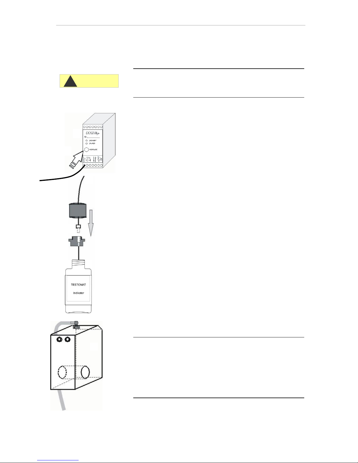
Insert indicator bottle
Open the lower housing door by pulling on the right side
Remove the closing cap of the indicator bottle
Remove the plastic bag from the inner side of the lower housing
door. It contains the screw cap with hole and the insert for
the screw cap
Join the parts together as shown below
Screw the hose connector of the suction hose hand-tight into
the insert
Plug the insert with screwed-in suction hose into the indicator bot-
tle
Now screw the screw cap with hole hand-tight onto the indica-
tor bottle
Open water intake
Open the lower housing lid
Slowly open the manual stop valve to prevent the measuring
chamber from overflowing. Configuring the flow regulator will take
some time during the initial commissioning.
Check the leakproof quality of water-conveying parts
If any water sprays out of the hose of the measuring chamber
, restrict the water intake to some extent with the manual stop
valve. The measuring chamber should be filled within two to six
seconds!
Automatic venting
After the device is switched on the indicator lines are automatically
vented and the measuring chamber purged, until indicator is detected
in the measuring chamber. The automatic venting cannot be interrupted. Wait until the venting process has ended and acknowledge
the "voltage failure" error message by pressing the horn key. The
device is then ready for use.
CAUTION
!
Page 24

Functions of the control and display elements
24
Device settings and data input
Before you configure the required settings and inputs to facilitate
operation of the device, please read the following information.
Functions of the control and dis-
play elements
The operating modes and measurement values are shown on the
display of the Testomat® EVO TH. The input keys for the programming (cursor block) and function keys are underneath the display.
Switching the Testomat® EVO TH device on/off
(1) External power switch
Use the external power switch to switch the device on or off
(2) Device fuse (internal)
These fuses protect the device or outputs against overload and
short circuit.
Descriptions of the fuses are found in Replacing fuses and under
Spare parts and accessories for the Testomat® EVO TH.
Switching on/off
Wait at least five seconds after switching off before switching back
on.
NOTE
Page 25
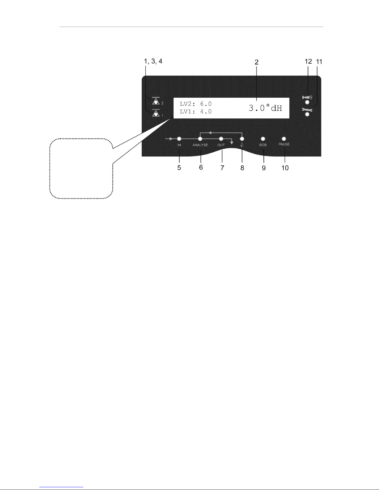
Functions of the control and display elements
25
Display functions
1 Limit value status indications (red/green)
When the limit values 1 are exceeded, indicator 1 lights up in red.
Falling under the limit value results in the indicator 1 lighting up in
green. The same function applies to limit value 2 and indicator 2.
2 Display
The current analytical result is shown as well as all important
states and programming data
The current measurement value appears on the right
The configured limit values LV1 and LV2 appear on the left. When
the measurement range is exceeded = "<" e.g.: < 0.05 °dH
Exceeding of the measurement range = ">" e.g.: > 10.0 °dH
The current analysis interval is suspended (analysis stops) and
the LED "Pause” flashes.
3 LV2 (red/green)
4 LV1 (red/green)
An LED lit up in green indicates that the limit value has been exceeded.
The LED lit up in red indicates that the limit value has been exceeded.
5 In (green)
The green LED indicates an opened inlet valve.
6 Analysis message (yellow)
The yellow LED indicates ongoing analysis.
7 Out (green)
The green LED indicates an opened outlet valve.
8 Dosing (yellow)
The yellow LED indicates the activated dosing pump.
9 "BOB operation"
The green LED indicates the activated BOB operation.
All error and warning messages are
shown in rotation
with the standard
display in line 1!
Page 26
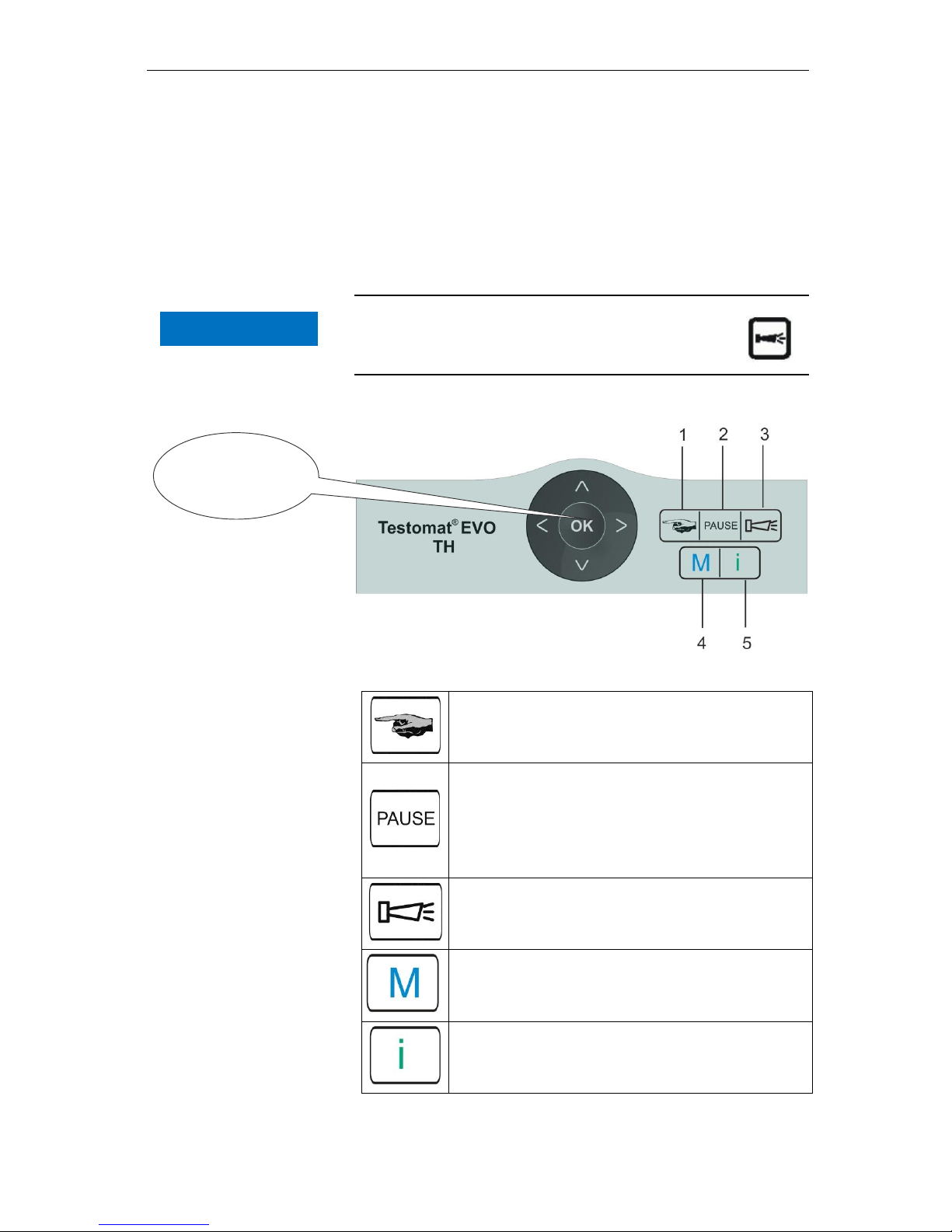
Functions of the control and display elements
26
10 Pause (green)
The flashing LED indicates the activated pause.
11 Service (yellow)
The yellow LED indicates that the maintenance period has
elapsed.
12 Alarm (red)
Indicates a functional error/error message or warning message.
Handling of error messages/warning messages
Eliminate the cause of the error and then acknowledge
the message with the "Horn" button
Control and function keys
Function keys
The “Manual" button is used to start manual anal-
ysis
The "PAUSE" button puts the device into standby
mode (no automatic analysis performed: analysis
stop). However, an ongoing analysis will not be suspended. The device only reverts to pause mode once
the analysis is complete.
Acknowledge error and warning messages with the
“horn" button
The "M" button is used to access the programming
menu for user- and device-specific settings
The "i" button is used to access all device infor-
mation and settings
Programming
keys
(Cursor block)
NOTE
Page 27
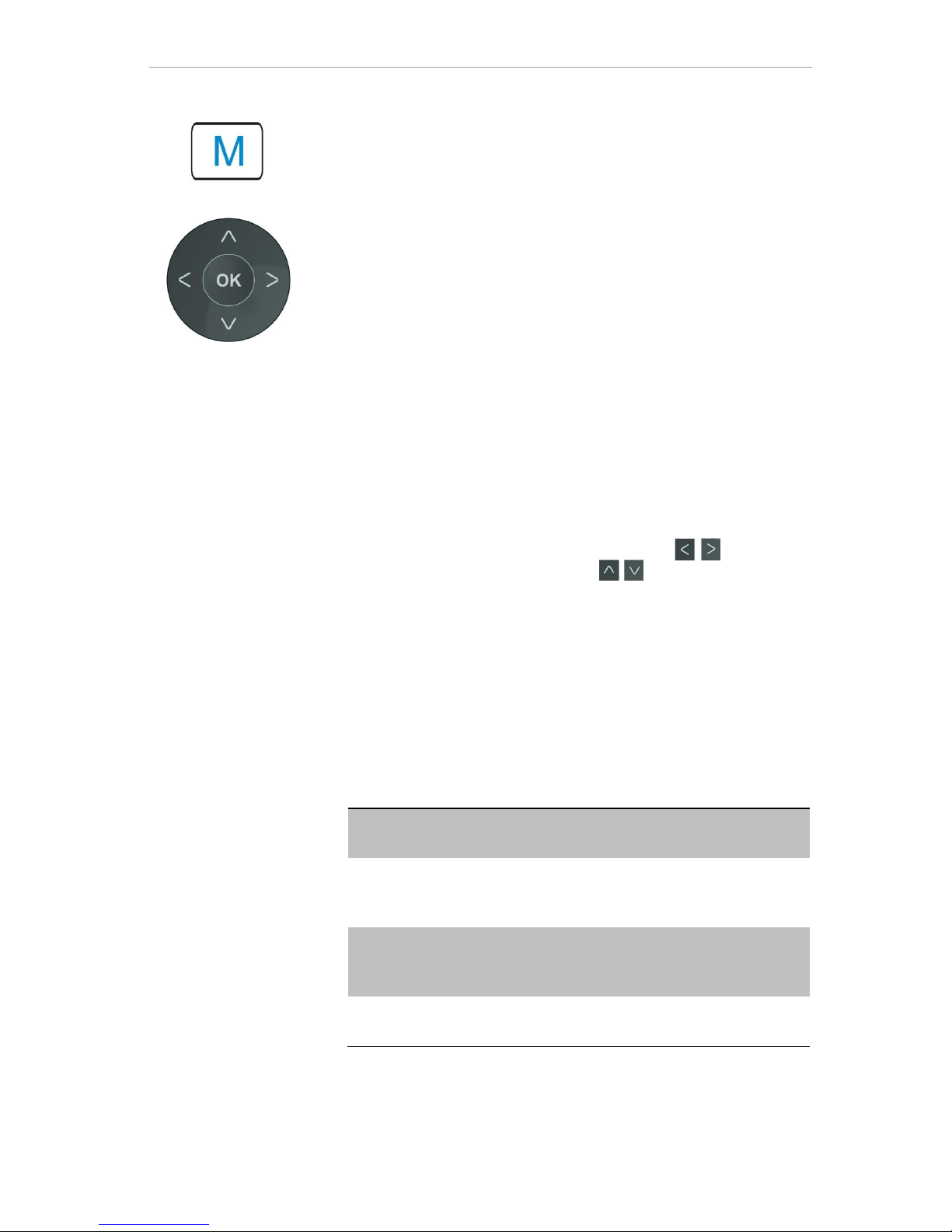
Functions of the control and display elements
27
Input programming data
If you configure settings or wish to input data or when changes are
required, you can call up the programming menu with the "M" button.
Pressing this button in the menu brings you to the higher-level menu
item or you can leave the programming menu.
Programming keys (Cursor block)
The following programming keys (cursor block) are used to navigate
in the menu, select the desired functions and input the required device- and system-specific data. The "OK" button is used to select the
submenu option and allows the selection or data input to be confirmed and adopted.
Indicator of the selected settings
If only one entry from a choice of multiple entries can be selected
from within a menu, a "*" symbol is shown. For all other entries, nothing is shown. Example: Configure indicator
If multiple entries from within a menu can be selected, a "√" is shown,
or “-”, for each of the active settings.
If inputting numbers is possible, the cursor keys are used to
change the position and the buttons to change the value.
Whatever the situation, to be adopted all entries must be confirmed
with "OK".
Operating system
Meaning of the symbols in the menu
In the menu, symbols are shown on the first line at the right-hand
edge. These represent the function keys, which can be used to facilitate navigation at this point in the menu.
Symbol
Meaning
M / I
"M” button, "I” button: Indicates the current
menu (basic program/service or information
Down or up arrows indicate that an additional
selection option is available over or under the
current menu option shown.
Right or left arrows mean that settings can be
viewed with the cursor keys, for example individual errors in the error list.
+
A "Plus" means that the selected menu option
includes an additional submenu.
Page 28
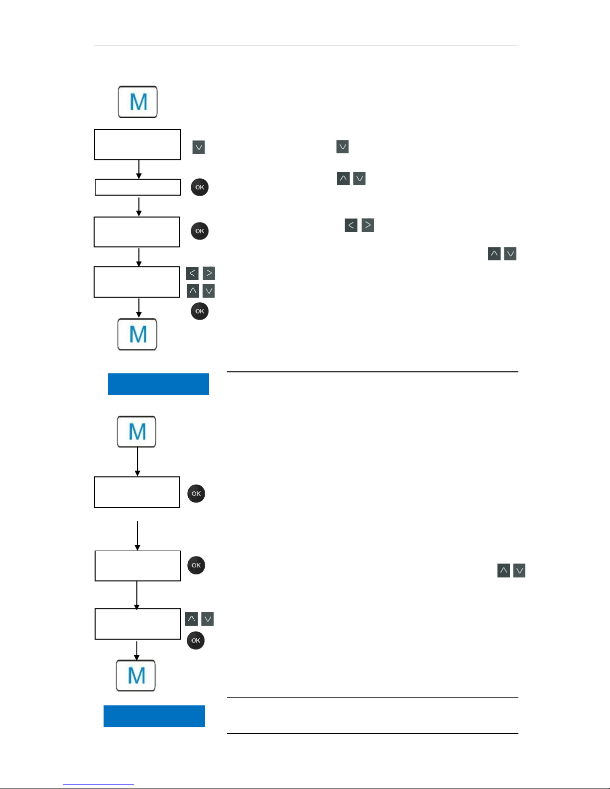
Functions of the control and display elements
28
Inputting date and time
Press the "M" button
The following selection appears: "Basic program" or "Ser-
vice"
Using the cursor block , select the menu option "Service"
Confirm your selection with "OK"
Using the cursor block select the desired menu option for
"Time Date"
Confirm your selection with "OK"
Move the cursor with the buttons to the desired position
in the time/date field
Select the desired figure by confirming with the cursor keys
Confirm the newly configured values for the time and date with
"OK"
If you do not wish to change the values, press no buttons for 30
seconds. The device will then revert back to the values in the op-
erating display.
Press the "M" button to leave the levels.
The clock continues to run even if the device is switched off.
Selection of functions (Example: "Select mode of operation")
Press the "M" button
The following selection appears: "Basic program" or "Ser-
vice"
Confirm "Basic program" with "OK"
Confirm the menu option "Mode of operation" with "OK"
The following selection appears: "Time controlled", "Vol-
ume interval" or "Volume and Time"
Select the desired function by confirming with the cursor keys
Activate the function with "OK"
(With an active function, an " * " appears at the end of the line)
This activates the selected function.
Press the "M" button to leave the levels.
If you have activated one function, the others are automatically deactivated.
Service
PROGRAM MENU
Basic program
SERVICE
Time Date
Time Date
Date 05.09.14
PROGRAM MENU
Basic program
BASIC PROGRAM
Mode of operation
MODE OF OPERATION
Time controlled
NOTE
NOTE
Page 29
Functions of the control and display elements
29
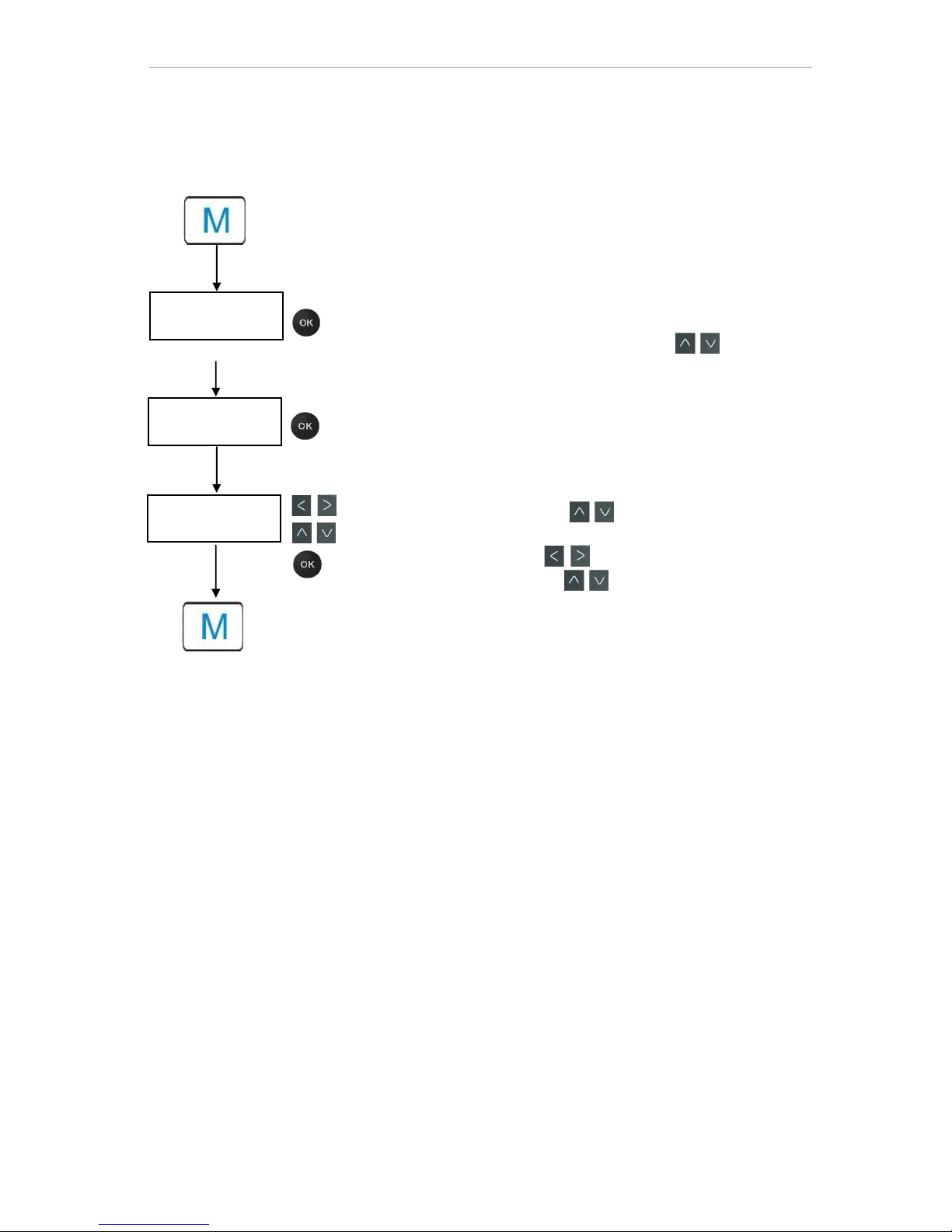
Inputting of data (Example: interval pause/quantity interval)
Using the menu option "Interval" you can program the interval
pause between two analyses.
To adjust the interval pause, proceed as follows:
Press the "M" button
The following selection appears: "Basic program" or "Ser-
vice"
Confirm "Basic program" with "OK"
Select the menu option using the cursor block
"Interval"
Confirm your selection with "OK"
The following selection appears: "Time" or "Volume"
Now confirm the menu option "Time" with "OK"
The cursor flashes on the first digit of the time setting: "2"
(You can input values from 0 to 99 minutes)
Confirm with the cursor keys to select the desired digit for
the first position
Move the cursor with the buttons to the second input field
Confirm with the cursor keys to select the desired digit for
the second position
Now confirm the input with "OK"
The input of the time interval is now complete.
When inputting the quantity interval, proceed when selecting the
menu option "Volume" similarly as to when setting time.
Select the four digits in sequence.
Confirm with "OK".
You can enter values from 1 - 9999 liters.
Press the "M" button to leave the levels.
PROGRAM MENU
Basic program
BASIC PROGRAM
Interval
INTERVAL
Time 2m
Page 30
30
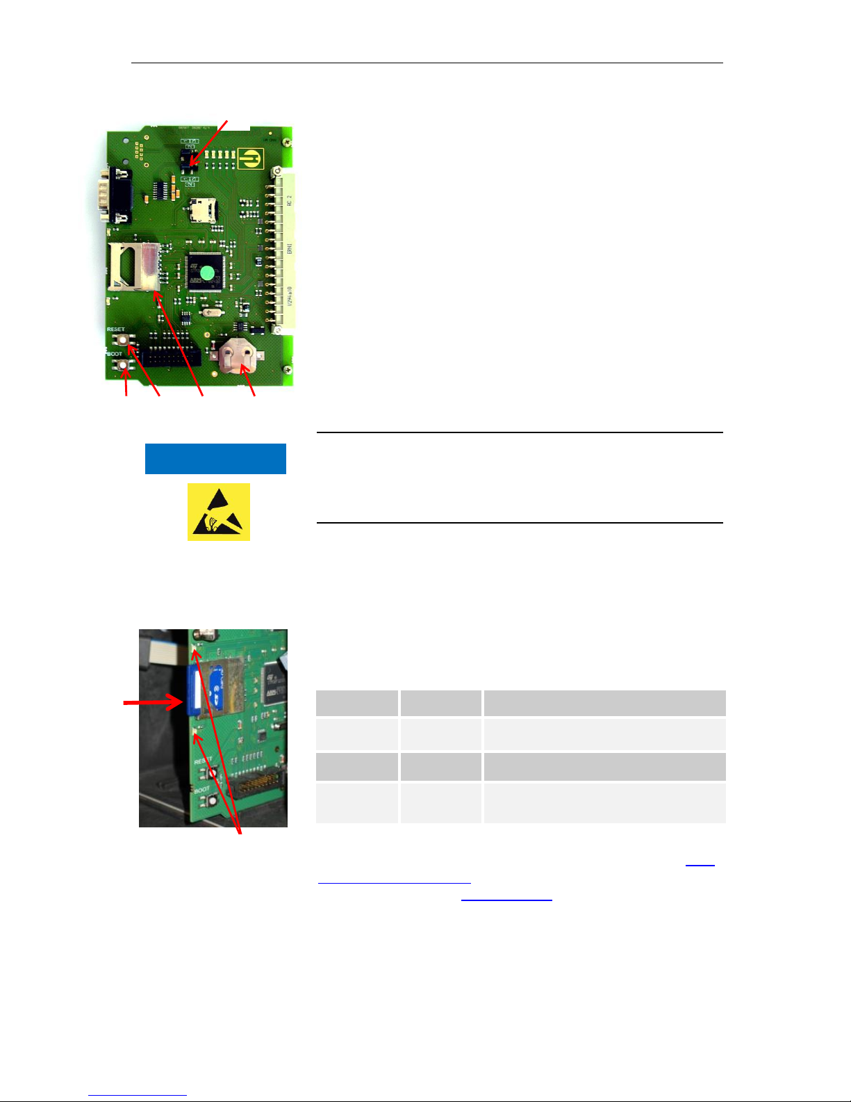
Control elements on the control board
Battery holder: The battery holder houses a CR2032 lithium
battery to retain the time setting even if the device is switched off.
Plug-in slot for SD card : SD or SDHC cards with a maximum
capacity of 32GByte are suitable. The card must be FAT or FAT32
formatted.
RESET button : To reset the controller, proceed as for switching
on and off
BOOT button : Only used when a menu-driven firmware update
is not possible.
Jumper field : Both jumpers must be plugged into the marked
Position 1. All other positions will render the serial interface unusa-
ble.
Mounting the SD card
Inserting the WLAN SD card
If the optional WLAN SD card is used for wireless access, please
observe the operating instructions in the User manual that accompanies the card.
Slide the SD card into the plug-in slot provided, as shown in the
diagram.
Gently press in the SD card until it audibly clicks into place.
The process of mounting the SD card is now complete.
Status displays of the SD card
Further information on possible errors is included in the section Error
messages/troubleshooting. How and whether these errors are shown
can be configured in the Alarm/message menu.
LED yellow
LED red
Meaning
On
Off
Read access on the SD card underway
Off
On
Writing process underway
On
On
SD card error has occurred (also shown
as text alert in the indicator)
NOTE
LEDs of the SD card
Observe ESD safety
precautions! See the
information on page 8
Page 31

Getting started
31
Getting started
Once you have completed the steps in the section Connecting indica-
tor, you can switch on the device.
Automatic venting
After the device is switched on the indicator lines are automatically
vented and the measuring chamber purged, until indicator is detected
in the measuring chamber. The automatic venting cannot be interrupted. Wait until the venting process has ended and acknowledge
the "voltage failure" error message by pressing the horn key. The
device is then ready for use.
You can skip automatic venting by keeping the OK button pressed
when switching on.
Since no settings in the programming menu can be configured while
the analysis is underway, press the PAUSE button once the venting
is complete or proceed to the programming menu before the first
analysis starts!
Now make the following settings, since these are imperative for
obtaining usable measurement values:
- Select Indicator type and container size
- Select display unit of measurement values
Now perform the first measurement by pressing the button. Upon
completion of the analysis, a measurement value must be shown.
If any error occurs, please refer to the section on Error messag-
es/troubleshooting and resolve the error.
Once the first analysis has been successfully completed, you can
adapt the device to your desired usage. The following sections will
set out all the configuration options.
NOTE
Page 32
Input basic programming data
32
Input basic programming data
Delayed reaction
During analysis, the response to any key presses may be delayed.
Select operating mode
Under the menu option "Operating mode" you can select the
type of analytical control. The Testomat® EVO TH gives you scope to
control timing or quantity via water meter or a combination of both.
Smallest pause interval = 0 minutes between analyses. Longest
pause = 99 minutes.
The analysis interval (interval between two analyses) is determined
by the configured purge cycle, the programmed pause time (interval)
and the duration of analysis. The duration of analysis is directly dependent on the measurement value.
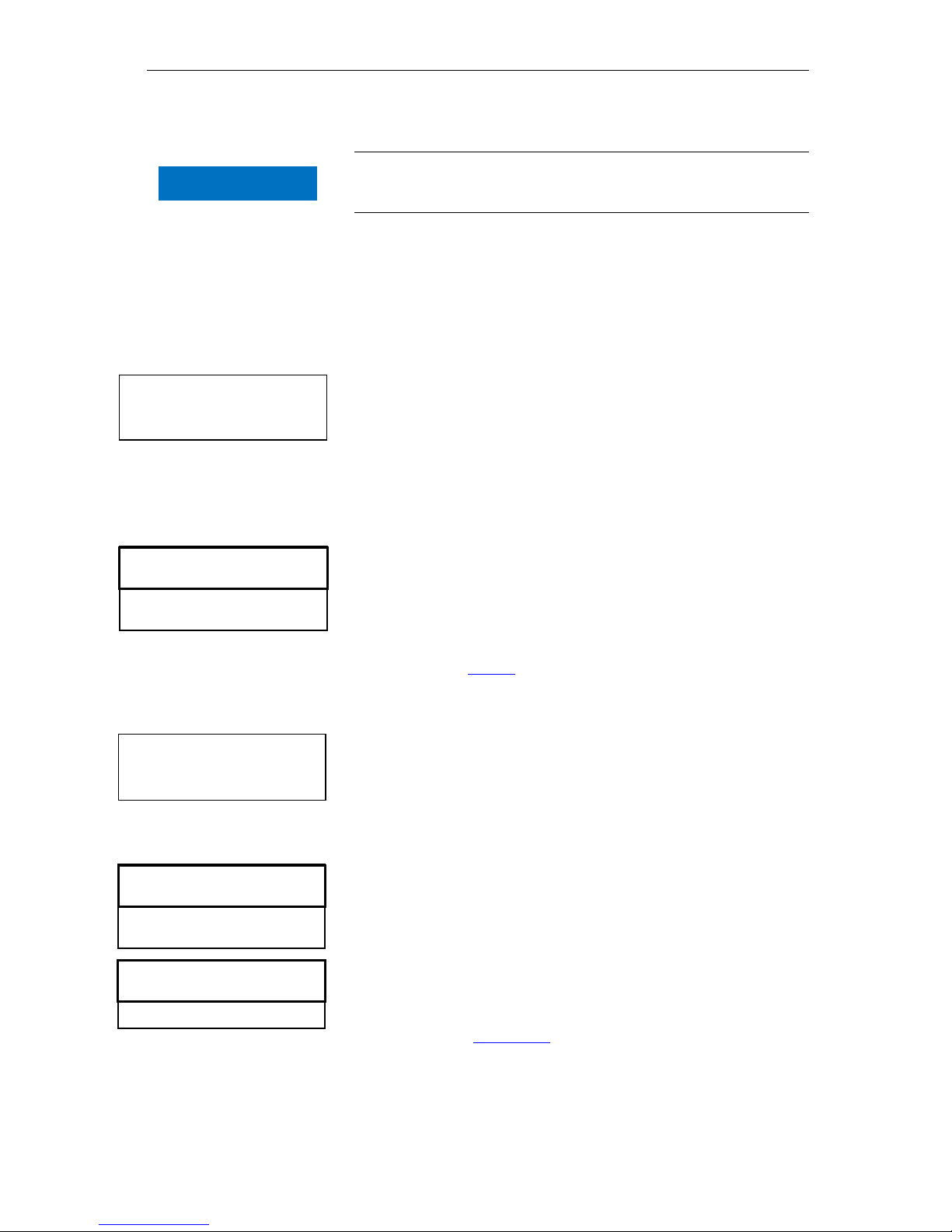
Select timing control
Select in the menu => Basic program=> Mode of
operation => Time controlled
Confirm the selection with "OK"
(An " * " appears at the end of the line)
(The factory default is "Time controlled" " * ")
Now enter the interval.
Select quantity control
Smallest interval = 1 liter, largest interval = 9999 liters. The analysis
is performed once the programmed quantity of water has passed.
Before the analysis, the line and measuring chamber are purged
(observe programmed purge cycles).
Select in the menu => Basic program => Mode of oper-
ation => Volume interval
Confirm the selection with "OK"
(An " * " appears at the end of the line)
Select in the menu => Basic program => Interval =>
Volume
Confirm the selection with "OK"
Input the corresponding flow volume in liters
Confirm the input with "OK"
Now select the water meter .
Timing control
Internal trigger by timer.
Quantity control
Triggered by water meter
INTERVAL
Time 10m
Volume 03501
MODE OF OPERATION
Time controlled *
Volume interval
Volume and Time
MODE OF OPERATION
Time controlled
Volume interval *
Volume and Time
NOTE
Page 33
Input basic programming data
33
Select quantity control/time priority
The analysis is performed once the programmed quantity of water
has passed. An analysis is always prioritized once the programmed
interval pause has elapsed.
Select the function
Select in the menu => Basic program => Mode of oper-
ation => Volume and Time
Confirm the selection with "OK"
(An " * " appears at the end of the line)
Select in the menu => Basic program => Interval =>
Time
Confirm the selection with "OK"
Select the pause time in minutes with the cursor keys.
(The factory default setting is 10 minutes)
Confirm the input with "OK"
Select Volume with the cursor keys
Confirm the selection with "OK"
Input the corresponding flow volume in liters
Confirm the input with "OK"
Configure interval (interval pause)
With time-controlled analysis trigger, the interval between two analyses is determined by the interval pause (plus purge cycle). The
shortest possible interval pause is 0 minutes. Non-stop analyses are
then performed. The largest interval is 99 minutes.
Select in the menu => Basic program => Interval =>
Time
Select the pause time in minutes with the cursor keys.
(The factory default setting is 10 minutes)
Confirm all entries with "OK"
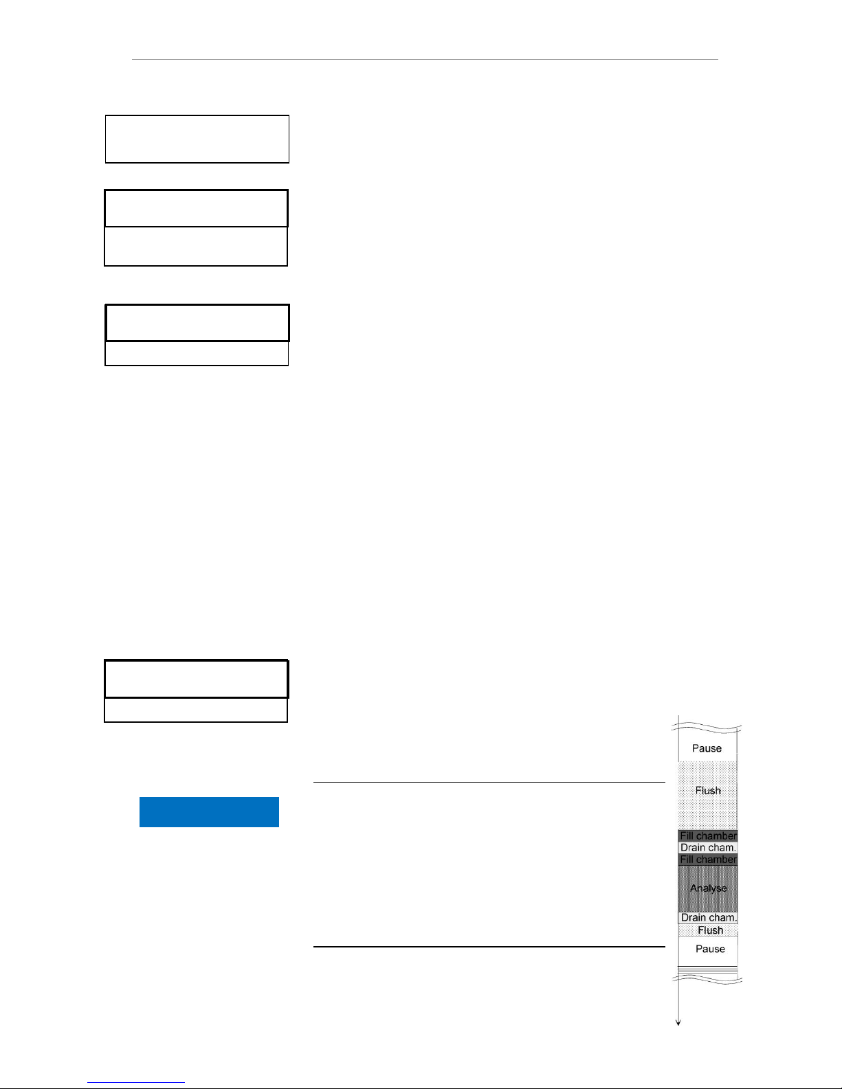
Duration of the analysis interval
The time for the analysis interval comprises the cumulative
time taken for the “Analysis interval", “Purge" and the duration of analysis, which depends on the measurement value
(see accompanying diagram).
When you perform additional purging via the AUX relay before or after the analysis, the duration of the analysis interval
will be extended accordingly.
Quantity control
Time priority
MODE OF OPERATION
Time controlled
Volume interval
Volume and Time *
INTERVAL
Time 10m
Volume 03501
INTERVAL
Time 10m
Volume 00001
NOTE
Page 34
Input basic programming data
34
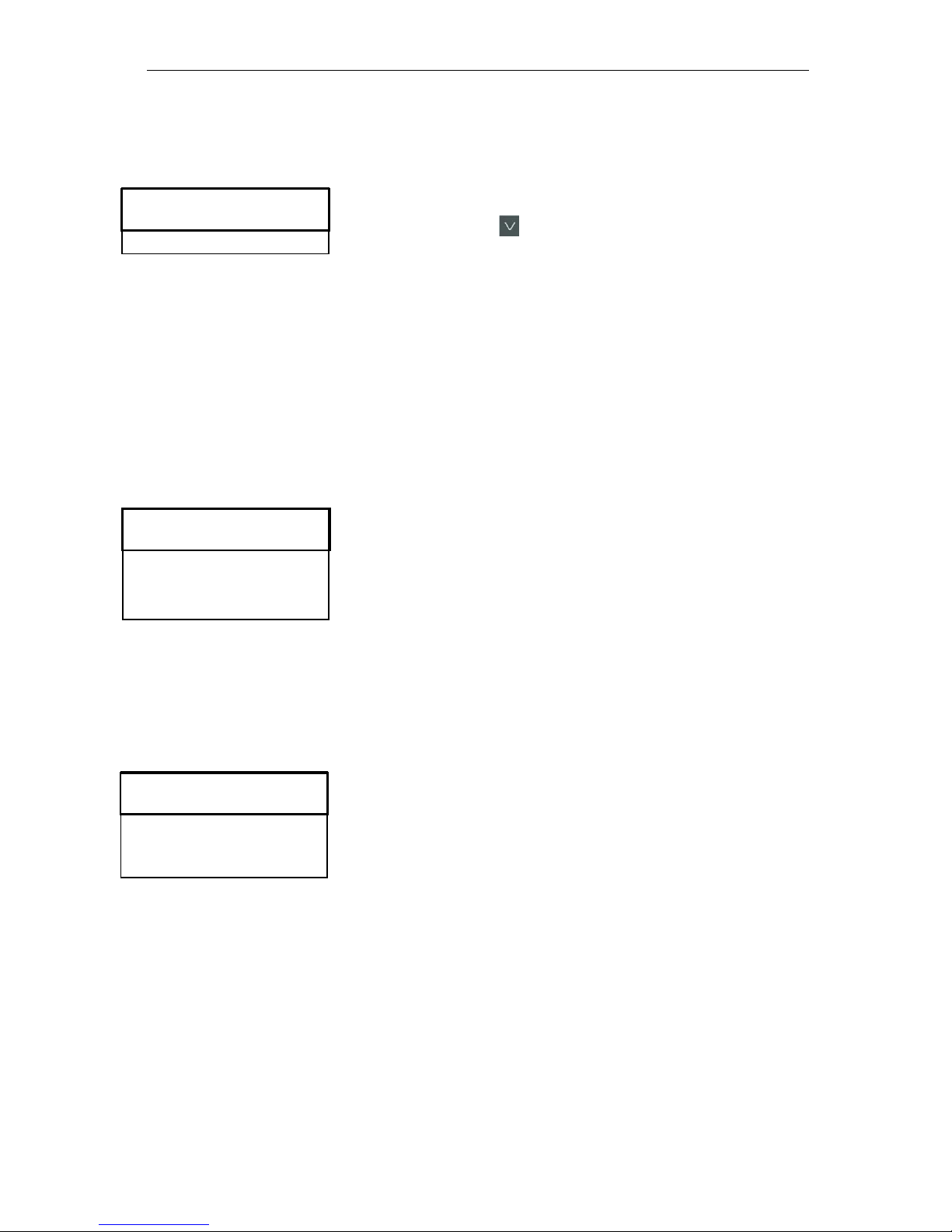
Select indicator type and container size
Press the "M" button
This brings you to the basic menu for "Basic program"
Confirm "Basic program" with "OK"
Keep pressing the button until the menu option
"Bottle size" appears.
Confirm this menu option with "OK"
You have the following selection.
Select the quantity of indicator
(The factory default setting is the 500 ml bottle " * ")
Confirm the selection with "OK".
(An " * " appears at the end of the line to indicate the selection)
Press the "M" button
Select the menu option "Type of reagent"
Confirm with "OK"
You have the following selection
Select the indicator type
(The factory default setting is the indicator type TH2005 " * ")
Confirm the selection with "OK"
(An " * " appears at the end of the line)
The " * " indicates the selection.
The indicator selection is now complete.
Select measurement value unit
You can program the unit of the value shown. Your selection options
include °dH, °f, ppm CaCO3 as well as mmol/l. All the following inputs
and indications will then be shown in the programmed unit.
Select in the menu =>Basic program=> display of
unit
Select the desired unit
(The factory default setting is the °dH unit)
Confirm the selection with "OK"
DISPLAY OF UNIT
Display °dH *
Display °f
Display pppm CaCO3
Display mmol/l
BOTTLE SIZE
500ml bottle *
100ml bottle
TYPE OF REAGENT
Type TH2005 *
Type TH2025
Type TH2100
Type TH2250
Page 35
Input basic programming data
35
Limit value monitoring
You can program the limit values to be stepless. The limit value
range is specified by the indicator type and programmed unit used.
You can monitor two limit values. For this purpose, each limit value
output is available. The functions of the assigned delay outputs can
be programmed independently of each other.
The limit value outputs are permanently assigned to limit values!
(GW1/2 are available on the LV1/2 terminals.)
LV1 = limit value 1 LV2 = limit value 2
If the limit value LV1 is exceeded, the limit value control indicator
lights up in RED and the relay output LV1 responds according to
the programmed switching function. If the limit value has not been
exceeded, the indicator lights up in GREEN. The same functional
approach applies to the limit value LV2.
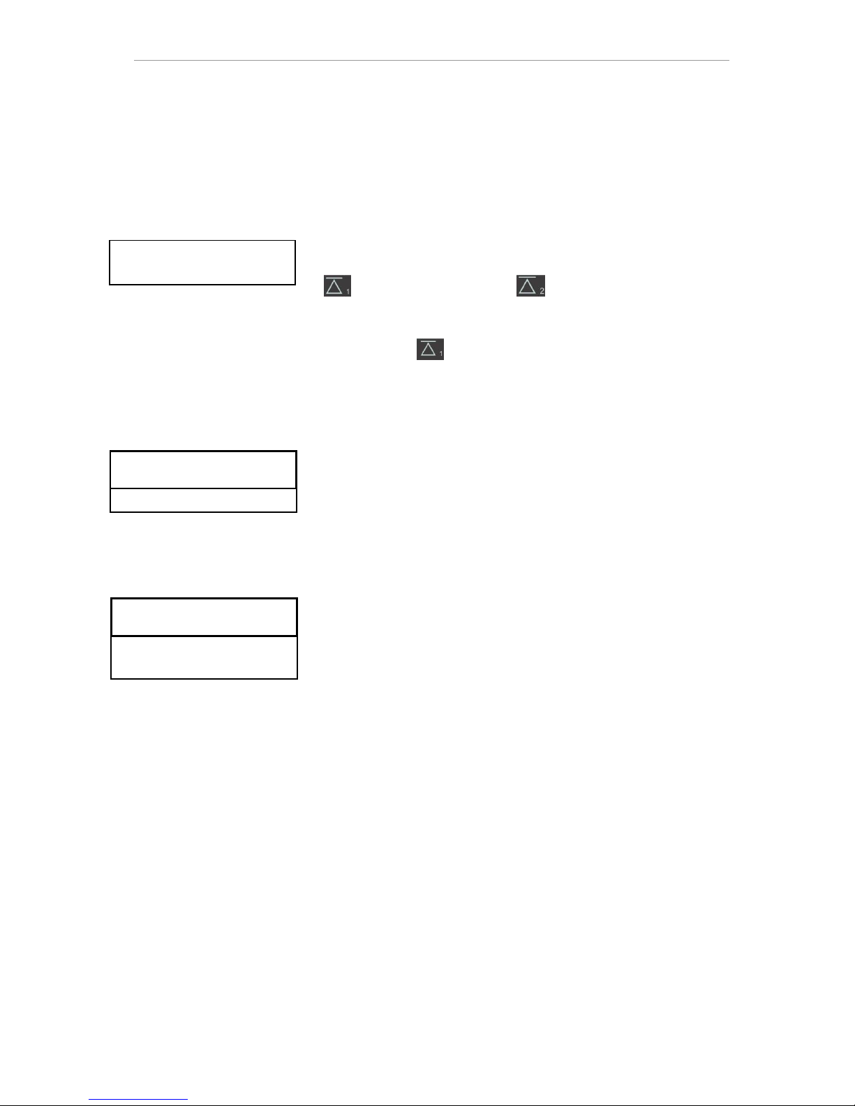
Entering the limit values
Select in the menu => Basic program => limit values
Input the values for "LV 1" or "LV 2"
Confirm the input with "OK"
Input operating mode of LV1 and LV2 limit value
outputs
Activate the operating mode for both relays via
=> Basic program => Function LV1/LV2
The following operating modes can be configured:
Limit value operating mode
A limit value may be defined for both relays. The relay switches when
the limit value is exceeded.
Two-point operating mode
(Output LV2 relay as a two-point controller)
If the LV2 upper limit value is exceeded, the LV2 output relay is activated. If the lower limit value LV1 is not attained, the LV2 relay is
switched off. Different values must accordingly be set for the limit
values LV1 and LV2. For example, for LV1 = 0.1 °dH and LV2 = 0.2
°dH.
The Output LV1 relay works independently as a limit value relay and
is activated once the LV1 limit value is exceeded.
For each relay, the switching function included via
=> Basic program => Relay LV1 or Relay LV2
can be separately configured:
Monitoring of
two limit values
LIMIT VALUES
LV1: 0.25 °dH
LV2: 0.15 °dH
FUNCTION LV1/LV2
Limit value *
Two point
Range
Page 36
Input basic programming data
36
Operating mode range
The relays switch when the predefined range between LV1 to LV2 is
exited:
If GW1 is not attained, relay 1 switches
If GW2 is exceeded, relay 2 switches
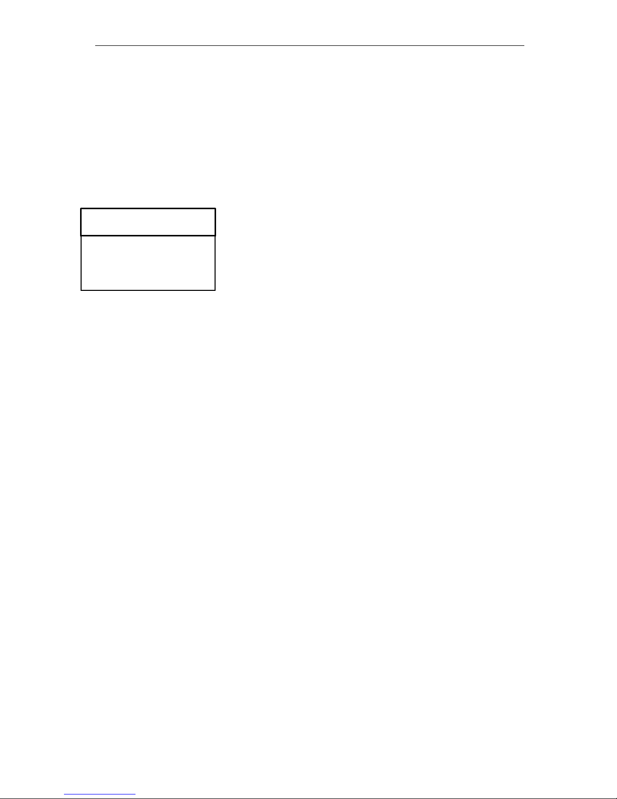
Switching functions of the LV1 and LV2 limit value outputs
Input the switching function separately for each relay via
=> Basic program => Relay LV1 or Relay LV2
Select Hysteresis, Duration, Impulse, Interval and Time.
(An " * " appears at the end of the line)
Input the time (only with impulse and interval switching function)
(Values from 00:00 up to 99 min. and 99 sec. can be entered)
Confirm the input with "OK"
Switching function only after multiple exceeding of limit value
The respective limit value output can be set to be triggered after the
first, second or third exceeding of the limit value.
This improves the assessment of the analysis e.g. after possibly insufficient purging of the sampling line.
The value may be separately configured for both the LV1 relay and
LV2.
The basic setting is 1 for LV1 and LV2. Switching occurs immediately
after the limit value is exceeded, with no delay.
When the number of times the limit value has been exceeded is “2”,
the next analysis is performed immediately after the first exceeding of
the limit value. Only after the limit value has been exceeded twice is
the corresponding output switched.
When the limit value has been exceeded “3” times, the corresponding
output only switches after the limit value has been exceeded three
times consecutively. This setting is only reactivated once the reading
falls under the limit value!
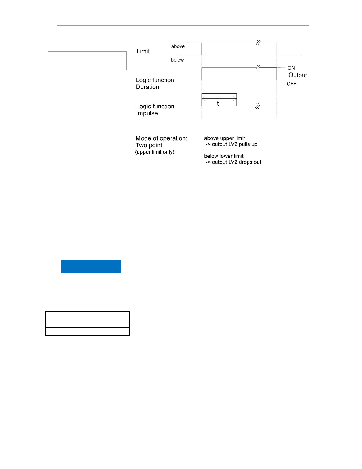
Switching function duration
If the limit value LV1 or LV2 is exceeded, the output LV1 relay or LV2
switches. If the limit value LV1 or LV2 is not attained, the corresponding relay is again deactivated.
Switching function impulse
If the LV1 or LV2 limit value is exceeded, the corresponding output
switches for the set time (t).
Regardless of the duration for which the limit value is exceeded, the
corresponding output remains always switched for the set time. A
renewed impulse is possible only once the reading falls under the
limit value!
RELAY LV1
Hysteresis 1
Duration *
Impulse
Interval
Time 00m:10s
Page 37
Input basic programming data
37
Input purge cycle
To guarantee that the sample being analyzed is current, the sampling
line must be sufficiently purged over its entire length. When the system is unused for an extended period and when the analysis interval
is considerable, a purge cycle of more than 60 seconds should be
selected. The purging is performed by simultaneously opening the
inlet and outlet valves of the Testomat® EVO TH.
Duration of the analysis interval
The analysis interval depends directly on the programmed purge
cycle. If for example a purge cycle of 90 seconds is set, the analysis
interval must be at least 90 seconds as well.
Internally enter the purge cycle
Select in the menu
Basic program => Flush time => Time
Input in the menu option "Time" the time in seconds(s).
(The factory default setting is 00 seconds(s))
Confirm all entries with "OK"
Enter excess
An additional purge cycle can be entered here after the limit value
has been exceeded, if the internal purging is not sufficient to flush out
the intake. The internal purge cycle is then extended by the set time.
Input the time in minutes (m) and seconds (s) in the menu option
"ExceedanceFlush".
(The factory default setting is 00m:00s )
Confirm all entries with "OK"
Diagram of the
switching functions
FLUSH TIME
Time 00s
ExceedanceFlush 00m:00s
NOTE
Page 38
Input basic programming data
38
Select water meter
For quantity-based analytical trigger, a water meter must be connected to the WM input (WM = water meter).
All settings are configured in the
=> Basic program => Water meter
menu.
Further information in the "Description of the signal inputs/outputs"
section
BOB operation (operation without constant
supervision)
The operation without constant supervision is safety-relevant when
using the device to determine water hardness and monitor steam
boiler systems in accordance with TRD 604.
If the BOB function is programmed, the device continuously checks
the available quantity of indicator.A calculation using the following
data is performed to determine whether sufficient indicator exists for
the next 72 h: purge cycles, current indicator fill level, interval pause
set, and the average measurement value of the previous 10 measurements.
BOB operation selection
Select in the menu => Basic program => BOB
Select "Function on"
Confirm the input with "OK"
BOB ON: Continual checking of the remaining indicator amount.
Alarm message "Indicator low" when dropping below the minimum quantity for the BOB period: BOB flash-
es, output ALARM is switched.
BOB off: No BOB function. Monitoring of remaining indicator only to
ascertain minimum quantity (fill level 10%)
Example:
BOB period = 72 hours
Number of analyses per hour = 10
Required quantity of indicator for 72 h = 72 h x 10 analyses/h x (3 x
30) μl/analysis = 64.8 ml.
(which equates to around 13% fill level of a 500 ml bottle)
Operating mode for BOB operation
In operating modes "Volume interval" and "Volume and
Time" no BOB operation is possible! Select only the "Time controlled"operating mode!
BOB
Function on *
NOTE
WATER METER
1 l/Impulse
2,5 l/Impulse
5 l/Impulse
10 l/Impulse
100 l/Impulse *
500 l/Impulse
1000 l/Impulse
Page 39
Input basic programming data
39
Description of the relay outputs
All relay outputs are designed as neutral contacts. This means the full
range of connection options is available to you. This facilitates the
switching of mains power, external power and direct switching of
inputs, e.g. a process control procedure is implemented.
Durability of relays
Please note the loading capacity of the relay and the overall loading
capacity (see Technical Data)!
Excessive loading may destroy the relay.
LV1 and LV2 limit value outputs
Two isolated relay contacts are provided to issue limit value exceeded alerts. For both contacts, the limit values, the number of times the
limit value has been exceeded up to switching as well as the switching function itself are freely programmable:
Function
Contact
Action
LV1
relay switches
when exceeding the limit
value of
limit value 1
Isolated change-over contact
Terminal 1: c / Central contact
Terminal 2: no / closing contact
Terminal 3: nc / Break contact
programmable:
- Permanent contact
- Impulse
(1-99 seconds/minutes)
- interval
(1-99 seconds/minutes)
- Area of lower limits
- Switches when the limit
value is exceeded once, twice
or three times
Function
Contact
Action
LV2
Relay switches
when exceeding
the limit value of
limit value 2
Isolated change-over
contact
Terminal 4: c / central contact
Terminal 5: no / closing contact
Terminal 6: nc / break contact
programmable:
- Permanent contact
- Impulse
(1-99 seconds/minutes)
- interval
(1-99 seconds/minutes)
- Area of upper limits
- Two-point
- Switches when the limit
value is exceeded once, twice
or three times
Further explanations can be found in the section "Operating mode of
LV1 and LV2 limit value outputs"!
Limit value 1 (LV1)
Terminals 1,2,3
Limit value 2 (LV2)
Terminals 4,5,6
CAUTION
!
Page 40
Input basic programming data
40
AUX (programmable functional output)
Function
Contact
Action
AUX
Programmable
function output
dependent on
the analytical
sequence
Isolated change-over
contact
Terminal 7: c / central contact
Terminal 8: no / closing contact
Terminal 9: nc / break contact
Programmable with
time interval, see below
This isolated relay output lets you set various switching functions set,
which depend on the analytical sequence.
Select in the menu =>basic program => Relay AUX.
You have the following configuration options:
Active "Before retry": In this case the relay AUX e.g. is used
to control an external purge valve. If a limit value has been ex-
ceeded, but the number set for the limit value occurrences was >1,
the relay switches before each measurement is repeated. The
purge procedure is performed for the set time. This can help pre-
vent measurement errors due to insufficient purging.
Active "Before analysis": e.g. for external purging switches
the relay for the set time before each analysis.
Active "During analysis"
Active "Before, during analysis"
Active "After analysis"
In addition, it is also possible to specify a time interval for which the
relay remains active.
Alarm (Fault signal output)
The device includes a relay "Alarm” output to notify faults.
A error is signaled via the LED alarm and the corresponding error
message is shown on the display. You can configure whether and
how this indicator should be shown.
Select in the menu
=>Basic program => Alarm/Message.
Select the signaling for each type of error.
You can set whether the error alerts
are not provided at all (by selecting "-" in the menu).
(Note: selection is not always available!)
Only in the indicator (by selecting "M" for notifica-
tion/message)
In the indicator and via the relay output (by selecting "A" for
Alarm)
.
AUX
Terminals 7,8,9
ALARME/MESSAGE
Fault dosing pump A
Fault optics A
Fault turbidity M
Fault soiling M
Fault analysis A
Meas. range exceeded M
Water low A
Indicator low A
Power failure A
Power failure 24 A
Ext. light influence A
SD Card n. inserted M
SD Card w. protected M
SD Card unformatted M
SD Card failure A
RTC bus error A
RTC data invalid A
BOB not possible A
Service exceeded -
RELAY AUX
Before retry *
Before analysis
During analysis
Before,during analysis
After analysis
Time 00m:10s
Page 41

Input basic programming data
41
Functions of the alarm output
The “Alarm" output is an isolated relay changeover contact. During
normal operation, the contact between terminals 10 - 11 is closed
and opened between 10 - 12. In the event of voltage failure, the contact between terminals 10 - 12 is closed and opened between 10 -
11.
The device includes a whole range of monitoring functions with following functions/performance of the "Alarm" output:
- In the event of permanent contact, the output remains "Alarm"
indefinitely activated (terminals 10 - 12 closed), pending resolution of the error.
The prerequisite here is that, in the menu
=> Basic program => Alarm/Message
the signaling "A" indicating the alarm for this error type is activated.
- The fault signal at the "Alarm" output is stopped when you
acknowledge the error with the "horn" button or by entering EXT.
ACK. With the help of these inputs and outputs and the transmission of measurement data (via 20mA current loop or serial RS232
interface), the Testomat can be operated at a master display.
- If the limit value is exceeded, there is no additional Alarm via the
Fault signal output!
A description of the possible causes of error is included in the section
on Error messages/troubleshooting.
Alarm/message – How to proceed when errors
occur
Error messages are adapted to the selected language, but can also
be identified by an error number, regardless of the language used.
All errors are, regardless of the settings made in this menu option:
- stored on SD card if Storing of error messages has been activated
- recorded in the error history (the last 20 error messages)
- and sent via the serial RS232 interface.
Detailed information on possible error messages as well as
their cause and remedy is found in Error messages / trouble-
shooting.
Error messages after self-test
For error messages caused by an improperly executed self-test, no
settings can be made; see Error messages after self-test.
Alarm
Terminals 10,11,12
NOTE
Page 42
Input basic programming data
42
Water shortage
The water shortage error is a special case, since one further setting
can be configured for this error. In the menu, under
=> Basic program => Waterlow count
the number of consecutively occurring errors before the alarm is triggered can be set. An error is then generated for each measurement
cycle.
Number of water shortage errors
This function is specially provided for systems subject to intermittent
low water pressure errors, which trigger a "Water low" error in the
device. The number 0 can be set for an immediate message, or the
setting can be raised to 250 occurrences before the error alert is
sent.
Error history
Select => Service => Error History
to call up error history.
Select "Show(OK)", to show the list of error messages.
Confirm the input with "OK"
Select an error message from the list using the arrow keys.
The time and date of the occurrence are shown.
Again, press "OK".
Now – depending on the error type – the start and end of the error
are shown.
If the error remains current, no end time is registered.
To delete the entire list, select
Delete(OK) 20
The number indicates the number of stored notifications.
The error history has room for up to 20 notifications.
SD Card n. inserted
12.09.13 09:00
12.09.13 09:00
12.09.13 09:05
WATERLOW COUNT
Count 0
Page 43
Input basic programming data
43
Description of the signal inputs/outputs
Switching of the signal inputs
Switch the signal inputs "Stop", "WM" and "Ext. Ack" only with
isolated contacts!
Switching with external voltage will damage the device!
Stop input
The stop input is intended for short-term suspension of operation,
e.g. when performing renewal work on softening plants, reverse osmosis or other water treatment systems. Generally speaking, the
system is not offline for more than six hours. The renewal phase of a
softening plant, for example, lasts three hours at most.
Function
Contact type
Testing
duration
Action
Stop
External analysis
stop (e.g. via flow
monitor or process
control)
Programmable:
break contact
or
closing contact
(isolated)
None
Where the contact is
opened or closed at
the input, no analyses are performed
If stop input is active, an analysis is prevented from starting, due for
example to an interval having elapsed. This may be required, if the
system lacks water. However, any analysis already started will not be
suspended. The analysis is completed and the device reverts to
pause mode.
Manual start has priority over stop input. That means that manual
analysis can still be started even when stop input is active.
Where the stop signal is present, the measurement value is shown
on the display and the LED pause flashes. If the stop signal is deleted, a new analysis starts immediately.
Accordingly, a short impulse on the stop input can help trigger an
analysis remotely.
Programming the "Stop input" switching function
Select in the menu => Basic program=> Function Stop
Select the contact type
Confirm the selection with "OK"
Stop
Terminals 19,20
FUNCTION STOP
Normally closed
Normally open *
CAUTION
!
Page 44
Input basic programming data
44
External delete (external acknowledge)
Function
Contact type
Testing
duration
Action
External delete
Deleting / acknowledging existing errors / alarms
Programmable:
break contact or
closing contact
(isolated)
none
Proceed as for
horn button
Via these terminals, all error messages can be acknowledged remotely. The contact type break contact or closing contact can be set
in the menu.
Here select => Basic program => Ext. Ack..
Input water meter
Function
Contact type
Testing
duration
Action
WM
Water meter
input
closing contact/break contact
(isolated!)
none
Determining quantity
to trigger analysis
Programming the water meter inputs
Select in the menu => Basic program => Water meter
Select the meter constant of the water meter
Confirm the input with "OK"
As required, configure the contact type (break contact/closing con-
tact) of the water meter in the menu => Basic program =>
function WM.
Current loop 0/4 - 20 mA
Function
Connection
Action
OUT
Current loop
0/4 - 20 mA
Burden max.
500 Ohm
programmable:
0 - 20 mA or
4 - 20 mA
Loading the current loop
The maximum load of 500 Ohm must not be exceeded!
In the event of faults and very long lines (around 20 m), the use of
shielded cable is possible.
WM
Terminals 17,18
OUT
Terminals 13,14
Ext. Ack.
Terminals 15,16
WATER METER
1 l/Impulse
2,5 l/Impulse
5 l/Impulse
10 l/Impulse
100 l/Impulse *
500 l/Impulse
1000 l/Impulse
NOTE
Page 45
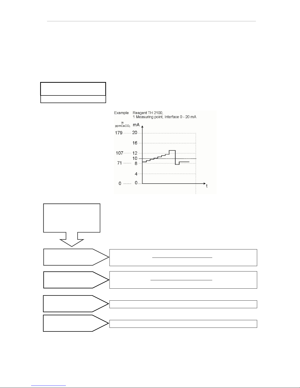
Input basic programming data
45
Monitoring the measurement point
Connecting a recorder allows the analytical results to be documented. For this purpose the device includes a programmable current
output (optionally 0-20 mA or 4-20 mA).
The following example indicates the course of the current within the
range of 0-20 mA.
Select in the menu
=>basic program => current interface type
Select the desired current range.
Confirm the selection with "OK"
Calculation of output currents
Depending on the selected function, the current range available is
either 0 – 20 mA or 4 – 20 mA. The resulting currents for the various
measurement values are shown in the form of the following formulas.
Measurement value
Current = x 20 mA
Measurement range upper limit
measurement value
current = x 16 mA + 4 mA
Measurement range upper limit
The current is set to 0 or 4 mA.
The current is set to 20 mA.
Measurement value = display value in the selected hardness unit
Maximum value = final value of the indicator used
(e.g. indicator type 2005 = 0.5 °dH)
Function
0 - 20 mA
Function
4 - 20 mA
Measurement range not
attained (e.g. <0.05 °dH)
Measurement range exceeded (e.g. >0.5 °dH)
How is the current calcu-
lated for a specified
measurement value?
CURRENT INTERFACE TYPE
Type 0 – 20 mA
Type 4 – 20 mA *
Page 46

Input basic programming data
46
Serial interface
The serial RS232 interface transfers measurement data and
alarms/notifications in plain text/ASCII in CSV format. It is always
active. The baud rate can be set to 2400, 9600, 19200, 38400 and
115200.
Transmission is in the 8 bit format, 2 stop bits, no parity.
A new measurement value is transmitted as soon as it has been de-
termined.
Select in the menu
=>Basic program =>Serial interface =>Baud
rate
Select the desired baud rate.
Confirm the selection with "OK"
New alarms are transmitted via the serial interface and some alarms
even when the alarm has been ended; see Error messag-
es/troubleshooting.
Notification format
The notifications are sent in a very similar format as the data placed
on the SD card:
The headings are not transmitted
Field separator is a comma
Decimal separator is a full stop
Each data set is started with the ASCII characters “02”
<STX> and terminated with “03” <ETX>.
Notifications and measured values can be distinguished by
evaluating the first characters: If “ME” is read, it is a meas-
ured value; with “AL”, it is an alarm/notification.
This corresponds to the format of the Testomat 2000® data
logger.
Example of measured value:
<STX>ME,TH2005,31.07.2013,08:09,0.050,°dH,limit
val.1:,0.200,°dH,limit val.2:,0.300,°dH<ETX>
Examples of notifications:
<STX>AL,Power failure,01.08.2013,06:30<ETX>
<STX>AL,turbidity,01.08.2013,07:30<ETX>
<STX>AL,turbidity inactive,01.08.2013,07:35<ETX>
For connection to a PC a so-called null modem cable is required.
SERIAL INTERFACE
Baudrate
Page 47
Input basic programming data
47
LCD settings
The Testomat® EVO TH comes with a large-scale backlit graphicenhanced LC display.
Adjust brightness and contrast in the menu =>Basic program
=> LCD settings
When you change a setting, brightness or contrast are
adapted on the display for previewing purposes. The settings are
thus not yet stored.
Press "OK", to confirm the settings.
Backlighting
There are extensive contrast adjustment options. Values between "3"
and "7" are advisable here.
In the event of very warm or cold ambient temperatures, the display
may no longer be optimally readable. Correct this by adjusting the
brightness and contrast until the display is again readable.
Description of the SD card functions
The SD card can be used to record measurement values and errors
as well as for importing and exporting the device settings.
Error and measurement value files are separately placed in subfolders arranged by year and month:
In the year folder, files including measurement values and errors
are arranged by month.
The format of the file names is:
ME<Year><Month>.csv for measurement values and
AL<Year><Month>.csv for errors/alarms.
In the year folders, as required, subfolders are placed for the 12
months of the year, within each of which a file for measurement
values and errors per day is placed.
The format of the filenames is ME<Year><Month><Day>.csv for
measurement values and AL<Year><Month><Day>.csv for errors/alarms.
Data is stored in the "Comma-Separated-Value" format, to facilitate
inclusion in spreadsheet programs and to allow it to be easily imported into databases.
NOTE
LCD SETTINGS
Brightness 8
Contrast 4
Page 48
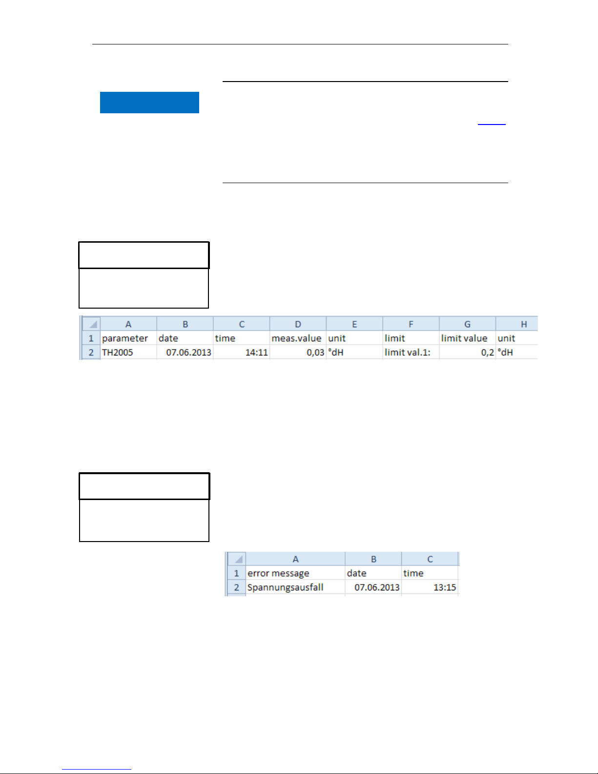
Input basic programming data
48
Link between time and correct data
To ensure that the naming of the file and the time and date details in
the file are correct, the time function must work properly. If the battery
drains, the date is automatically set to 1.1.2011, 12:00 and the data is
stored. Data is not lost, since new measurement values and errors
are appended to existing files. However, only one file is described in
each case, since the month and day are not subject to change.
Storing measurement values
The storing of measurement values on the SD card is activated when
in the menu
=> Basic program => Function SD-Card => Store
measurement
is activated.
Example for a CSV file imported into Excel:
Within the file, the comma is included as a separator in the first line
"sep=,", so that it can be imported directly into Microsoft Excel. If
OpenOffice/LibreOffice Calc are used, this line appears after the import. It may be deleted.
Store error
The storing of the error on the SD card is activated, when in the
menu
=> Basic program => Function SD-Card => Store
error
is activated.
Example for a CSV file imported into Excel:
Within the file, the comma is included as a separator in the first line
"sep=,", so that it can be imported directly into Microsoft Excel. If
OpenOffice/LibreOffice Calc are used, this line appears after the import. It may be deleted.
FUNCTION SD CARD
Store measurement
Store error Import basic data
Export basic data
NOTE
FUNTION SD CARD
Store measurement -
Store error
Import basic data
Export basic data
Page 49
Input basic programming data
49
Interim storage for a non-inserted SD card
Even if no SD card is currently inserted, no measurement values and
errors are lost, since the most recently error and measurement values, which have not yet been written into storage, are saved on internal interim storage (ring memory).
As soon as an SD card is inserted, the interim stored data is transmitted during next write operation.
The capacity of this interim buffer is 50 error and 100 measurement
values. After this point, the oldest values will be overwritten.
Capacity of the SD card
The storage requirement for 10,000 measurement values amounts to
around 1MByte. If error messages occur for one percent of the
measurement values, a 2GB SD card for example may have around
19 million measurement values and errors.
Export basic programming data
In the menu
=> Basic program => Function SD-Card => Export
basic data
all settings of the Testomat device can be stored in a file on the SD
card.
This function is recommended for:
- Storing multiple configuration profiles for one device
- Transferring settings onto other devices
- Configuring multiple devices with identical settings
- Remote maintenance / support via transfer of the basic programming data
The filename is preset to "bdata00.ini" (for "Basic Data" / basic programming data). The digits are adjustable, meaning that in total 100
different files from "bdata00.ini" up to "bdata99.ini" can be selected.
The files are always stored in the root directory of the SD card.
Editing the file
The settings are in the file in text form and can be displayed or edited, with for example the notepad application on a PC. Use a simple
text editor, not a word processor, since otherwise the formatting may
be changed!
If files (for example when creating profiles) are later renamed on the
PC, please note that the indicator of the Testomat device is limited to
24 characters. Longer filenames cannot be distinguished on the Testomat!
FUNCTION SD CARD
Store measurement
Store error Import basic data
Export basic data
NOTE
Page 50
Input basic programming data
50
Import basic programming data
Select in the menu
=> Basic program => Function SD-Card => Import
basic data
one of the files in the root directory of the SD card with the ending
"ini" using the arrow keys.
Import the files with "OK".
If an error message occurs during the import, the format of the data is
defective. This may occur if the file has been edited. In this case no
settings are changed. Use a simple text editor for editing (e.g. WordPad), not a word processor, since otherwise the formatting may be
changed!
All device settings are imported except
- Language settings
- Operating hours counter
- Indicator fill level
- Password
Password protection
For data input and settings in the basic program, a four-digit password can be used. If you have forgotten your password, please contact your Heyl Neomeris service partner or water supplier.
Password input
Press the "M" button
This brings you to the basic menu for "Basic program"
Confirm "Basic program" with "OK"
The cursor flashes in the "PW: 000” field.
Use the cursor keys to input the sequence of digits and confirm
with "OK".
You then see the selection menu for the basic programming.
No export of passwords
Please note that in Exporting settings, the password is not saved!
FUNCTION SD CARD
Store measurement
Store error Import basic data
Export basic data
NOTE
BASIC PROGRAM
PW: 0000
Page 51
Input basic programming data
51
Change password
In the menu
=>Basic program => Change Password
the password can be set. For this purpose, the existing four-digit
password code must be input, before the new code, which includes
four digits, can be input.
The default password on delivery is 0000.
Password protection
In the menu
=>Basic program => Password protection
the set password can be activated. For this purpose, the existing
four-digit password code must be input first.
Firmware update
Menu-driven firmware update
In the menu
=> Basic program => Firmware update
the operating software of the Testomat device is updated. For this
purpose, you need an SD card.
Implement the firmware update as follows:
Download the firmware update for the Testomat® EVO TH from the
Heyl website and save it in the root directory of the SD card to be
inserted into the Testomat® EVO TH
Insert the SD card into the Testomat® EVO TH
Select in the menu
=> Basic program => Firmware update
Confirm the selection with "OK"
Select the filename of the update. If only one file exists, only con-
firmation is required.
Confirm the selection with "OK"
The Testomat restarts and implements the update. In this mode, although no text is output, the status is indicated via the LEDs of the SD
card as well as those on the control card.
During the firmware update, the red LED lights up next to the SD
card plug-in slot (which indicates that the so-called bootloader
is active).
NOTE
CHANGE PASSWORD
Old: 0000
New: 0000
PASSWORD PROTECTION
Active: -
PW: 0000
FIRMWARE UPDATE
Execute (OK)
Observe ESD safety
precautions! See the
information on page 8
Page 52
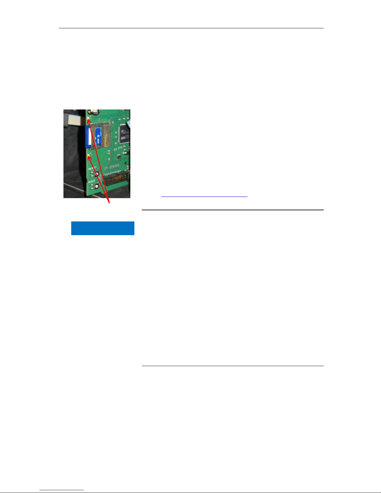
Input basic programming data
52
The programming progress is indicated as bars with five LEDs on the
control card:
Initially, only LED1 flashes (in the vicinity of the plug connector to the
motherboard) slowly (once every two seconds) and later permanently, whereupon the next LED begins flashing. The process is repeated
until all LEDs light up permanently.
The firmware update is now complete. The Testomat is started automatically with the new operating software. The complete firmware
update takes around 70 seconds.
Possible errors:
If both LEDs flash or light up next to the SD card, there is a prob-
lem with the SD card itself. The update could not be started. The
existing firmware remains unchanged.
If the LEDs next to the SD card are inactive, but the LEDs on the
control card flash quickly (10x per second), an error has occurred
during the update.
See Firmware update error messages.
Obtain the settings after the firmware update
After a firmware update, the device may be in an undefined state.
After a firmware update, basic programming should therefore always
be performed. If the settings have been preserved, it is advisable to
export the settings onto the SD card before the firmware update and
after the firmware update, to import the saved settings
Passwords
The set password is preserved even after the firmware update.
Error and update log
During the update a file called "update.txt" is written onto the SD
card, which includes a record of the update progress and any errors
having occurred in the process.
Open these files with your editor of choice (e.g. Notepad), to read the
relevant content.
The file is not deleted, but supplemented. If the same SD card is always used for a device, it will provide an overview of all the firmware
updates performed for the device in question.
NOTE
LEDs of the SD card
Page 53
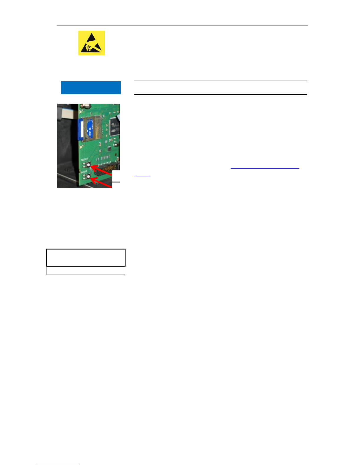
Input basic programming data
53
Manual firmware update
The manual firmware update facilitates the recovery of software after
failed firmware updates. The indicator and device buttons are not
used in the process.
An SD card with a firmware file must be inserted in the device.
Press and hold the "BOOT" button on the control card. Than
briefly press the “Reset” button .
The update process progresses automatically. Progress is shown
by the LED lights.
In case of several software versions on the SD card the newest
version is loaded.
Release the “BOOT” button when the update starts.
For information on handling errors see Firmware update error mes-
sages.
Maintenance
As a reminder for maintenance, an interval in days can be set. Once
the interval has elapsed, the message "maintenance exceeded" is
issued.
Configuring the maintenance interval
Select the menu
=> Basic program => Service Time => Interval
200d
Change the value with the cursor keys
Confirm the input with "OK".
Acknowledge the maintenance
When maintenance has been performed, you must acknowledge it.
This allows the reverse-running day counter to be reset to the configured value, whereupon the maintenance interval restarts afresh. The
counter indicates how much time remains until the next maintenance.
Select the menu => Basic program => Service Time
=> Acknowledge(OK) 200d
Confirm the input with "OK"
The counter is reset to the value set during the maintenance inter-
val.
NOTE
SERVICE TIME
Interval 200d
Acknowledge(OK)
Observe ESD safety
precautions! See the
information on page 8
Page 54
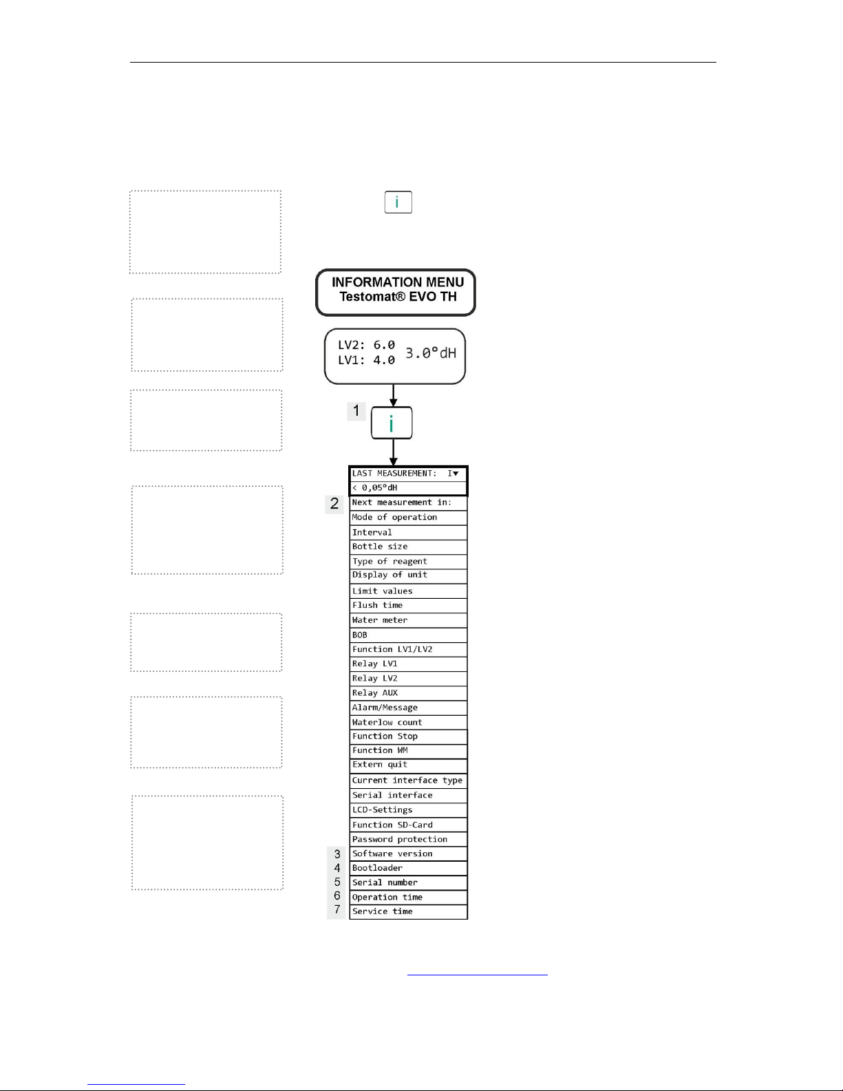
Information menu "i"
54
Information menu "i"
The information menu gives you scope to query current settings and
states of the device.
Call (1)
The button allows you to call up the information menu.
Scope for queries: Operating values and program values, such as
software version, container size and indicator type
Further notes on programming and setting individual menu options
can be found in Basic programming data.
Software version (3)
Indicator showing the installed
software version
Bootloader version (4)
Indicator showing the installed
bootloader version.
The bootloader is needed to
execute the firmware update.
Serial number (5)
Indicator showing the serial
number of the device.
Call (1)
Remote access in the information menu to check or query
the settings and operating
values.
Next measurement (2)
Indicator showing the time
remaining before the next
measurement.
Operating time (6)
Indicator showing the operating
time of the device. Can be
reset in the service menu.
Maintenance (7)
Indicator showing the time
before the next maintenance.
Once the maintenance is
acknowledged, the counter is
reset.
Page 55
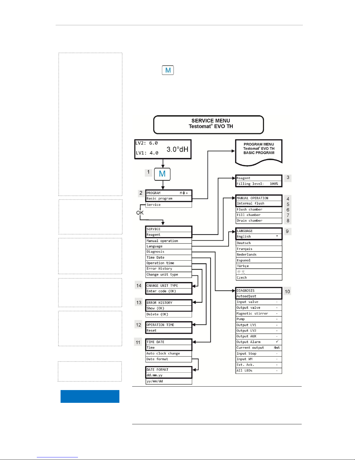
Service menu
55
Service menu
Call: (1)
The button allows you to call up the program menu. Use the
cursor keys to select the menu option "Service".
Settings: Reset the indicator fill level, use manual operation, language setting, diagnosis, time, operating hour counter, view/reset
error history
Availability of functions
All manual functions can be selected only in an analysis pause. During manual operation, no analyses are performed. All signal inputs
and outputs are locked.
Service (2)
Indicator fill level (3)
Input the new fill level for each
refill or when changing the
bottle of the indicator. Just as
with the menu option for input
of the fill level "Reagent filling
Level (0 - 100 percent)”, which
can be selected with "OK", the
value is preset to 100 percent.
If you have connected a full
bottle, confirm this value with
"OK".
If the filling of the bottle deviates from this figure, enter the
corresponding value.
Manual operation (4)
Once you have confirmed the
message box (4) with "OK",
you can select the desired
function with the arrow keys
and execute it with "OK".
These functions facilitate functional testing and commissioning.
Internal purging (5)
Start the purging of the sampling line through the internal
valves with "OK". Another
press on the "OK" button ends
this function.
Purge measuring chamber
(6)
The measuring chamber is
purged with "OK". Pressing
again stops the purging and the
measuring chamber is emptied.
Empty chamber (8)
With "OK”, open the outlet
valve to discharge the water
into the measuring chamber.
Another press on the "OK"
button closes the outlet valve.
Fill measuring chamber (7)
With "OK”, the measuring
chamber is filled once, which
allows the optical water detection function to be checked.
Time and date (11)
To set the time, date and
summertime adjustment.
NOTE
Page 56
Service menu
56
Language (9)
Select the desired language for the indicator. The number of installed
languages may vary.
Diagnosis (10)
The diagnosis menu allows you to perform an automatic comparison
for the amplifier of the receiver diode and the LEDs. You can also
switch and reset EV, AV and all outputs as well as test the current
loop.
The "Current output" point allows the current loop to be tested. The
"OK" button allows switching between minimum and maximum current. At 0-20 mA, the variation is between 00mA and 20mA!
Operating time (12)
After replacing a dosing pump or mounting the measuring chamber,
you can reset the current operating time with Reset to 0 hours.
Error history (13)
Faults are recorded in the error history and stored if the incident is
programmed as an alarm or message. If for example the lack of an
indicator is not programmed to trigger an alarm/message, this is also
not registered in the error history. Up to 20 error messages are recorded. The information stored in each case includes the point in time
(day, month, year and time) and the type of error.
Changing device type (14)
Under certain circumstances, this special function can be used to
programme the firmware of another device type into this device.
Please contact our support team for more information.
Basic programming
This menu option is reached after confirming the "M" button (Menu).
Here you can implement the basic programming of the device and
call up various functions for service purposes.
In basic programming, the following abbreviations are used in the
corresponding menu options:
s = seconds; m = minutes; h = hours; T = days; l = liters
English *
Deutsch
Français
Nederlands
Espanol
Türkçe
中文
Czech
Revert to factory
default basic setting
To retrieve the factory
default basic programming, the device
should be switched on
while pressing and
holding the button.
CAUTION! The most
recent programming
will be lost!
Page 57
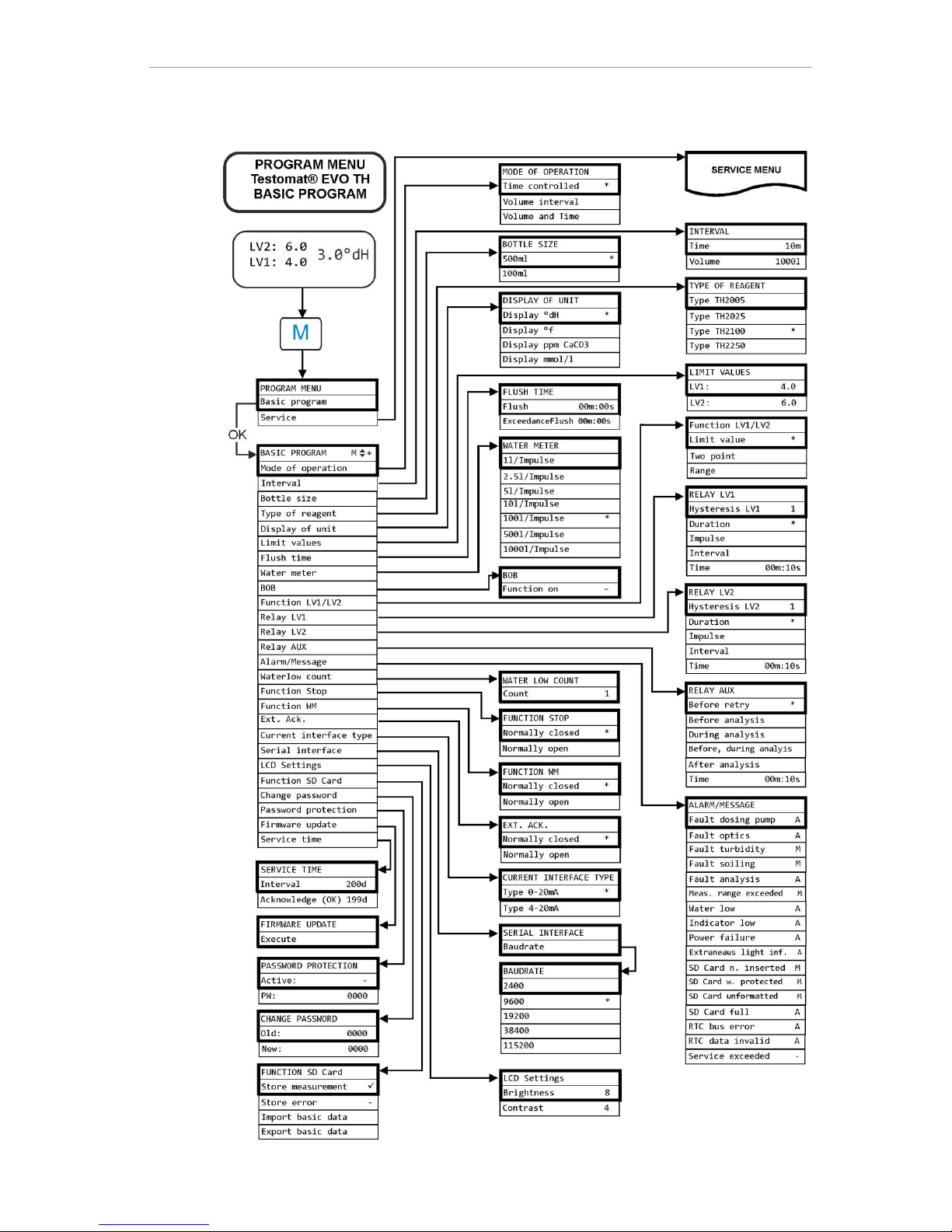
Structure of basic programming
57
Structure of basic programming
Page 58

Error messages/troubleshooting
58
Error messages/troubleshooting
Errors will be recorded in the error history as far as capacity allows
(after which the oldest message will be deleted).
In addition, error messages can be stored on the SD card, if in the
menu
=> Basic program => Function SD-Card => Store
error
has been activated.
Details of errors are always sent via the serial RS32 interface.
Errors are handled differently depending on type:
All errors, for which user access is required to recover the function of
the device, are shown as alerts. In addition, an alarm may be triggered. However, it is not possible to completely disable the message,
since the selection "–" is locked in the menu.
In the event of such error occurring, the device reverts to pause
mode. When these errors are acknowledged with the horn button,
they are deleted and the pause mode can be ended. In the event of
any recurrence, the set action (message or alarm) is again triggered.
For such errors, the time of occurrence is recorded in a log.
All errors that occur only intermittently, which means they impact only
on the analysis process, are cyclically checked by the device and
automatically deleted when no longer present.
If these error messages are acknowledged, only the alarm is deactivated. The error message is not, however, deleted. It is deleted only
when the error no longer occurs after rechecking (namely, during the
following analysis, either automatically or when manually started).
These errors can also be ignored when in the menu Alarm/message
"-" is selected.
In the Error history the start and end time are logged. Likewise, two
notification messages are written via the serial interface and onto the
SD card with the start and end times of the error (see Message for-
mat).
Regardless of the case, the analyses are continued.
Page 59
Error messages/troubleshooting
59
Error number/error message
Description, possible
causes
Solution, troubleshooting measures
01 Power failure
Prior power failure (also
when switching off)
Check power supply
02 Power failure 24V1
Failure of the internal
24V power supply
Replace 24V fuse
For all other defects, the device must be
repaired
03 RTC bus error
Connection to clock
broken
Device should be repaired, so that the clock
works. If the time is not relevant, you can
keep using the device.
04 RTC data invalid
Device was switched off
and backup battery for
clock is empty
Lithium battery is used up. Replace battery.
05 SD Card n. inserted
The function to store
measurement values
and/or error was activated, but no SD card was
inserted
Insert SD card
06 SD Card w. protected
Card is write-protected
The write-protect tab at the side of the SD
card must not be set to "LOCK"
07 SD Card unformatted
Card not formatted or
formatted with an invalid
file system
Format the SD card with a FAT or FAT32 file
system
08 SD Card failure
Error when accessing
SD card, because the
file is write-protected or
the card is full or defective.
Remove the write protection of the file
Wipe the card
Insert new card
12 Meas. range exceeded
The measurement scope
is exceeded
Select other indicator type (basic program)
13 Service exceeded
The maintenance inter-
val was exceeded
Perform maintenance
30 Fault dosing pump1
Dosing pump is defec-
tive
No dosing message
from dosing pump
Check the cable to the dosing pump to en-
sure a correct connection
Replace dosing pump
33 Fault optics1
Error in the optical unit
(light source or receiver
defective)
Swap measuring chamber mounting
34 Fault turbidity
The water is too cloudy /
soiled
Install an upstream water filter
35 Fault soiling
Viewing windows are
soiled
Clean viewing windows
Page 60
Error messages/troubleshooting
60
Error message
Description, possible
causes
Solution, troubleshooting measures
36 Fault analysis1
No correct analysis, e.g.:
Air in dosing hoses?
Insufficient mixing
Indicator expiry date
exceeded
Foreign indicator in the
device
Re-tighten dosing pump connections
Renew intake insert in bottle
Check suction and pressure hose for dam-
age
Replace stirring bar
Replace indicator, only use Heyl Testomat
2000® indicator
37 Indicator low
Indicator minimum quan-
tity is not attained
- without BOB: 10%
- with BOB: according to
calculation
Check indicator fill level, Insert new indicator
bottle and Reset indicator fill level.
38 Water low
1 2
No water intake despite
permanent lamp "IN"
Intake pressure too low
Water remains in the
measuring chamber, despite the lamp "OUT"
lighting up
Check water inflow
Plug at the inlet valve corroded
Clean filter sieve
Replace valve block
Remove the pressure regulator core
Outlet valve blocked or defective. Clean or
replace valve
39 Ext. light influence
Photo sensor not dark-
ened
Permanently illuminated
LED in measuring
chamber
Shut the device door
Avoid sunlight
Hardware problem. Send device for repair.
40 BOB not possible
The quantity of indicator
no longer suffices for 72
hours operation without
supervision
Insert new indicator
66 Fault auto remove
air
Automatic venting has
failed.
Possible causes can be problems with the
dosing pump, optics, cloudiness, dirt contamination, analysis error or water shortage. To
determine the error more accurately, keep
the OK button pressed and restart the device. Another error message is displayed.
Proceed to troubleshooting, as described in
the error message.
1
Device reverts to pause mode until the error is acknowledged
2
The error Water shortage is treated as a special case here, as this
is the only case in which the number of consecutively occurring errors
in the menu =>Basic program => Water low count can
be adjusted until the relevant alarm or message is triggered. One
error is generated per measurement cycle.
Page 61
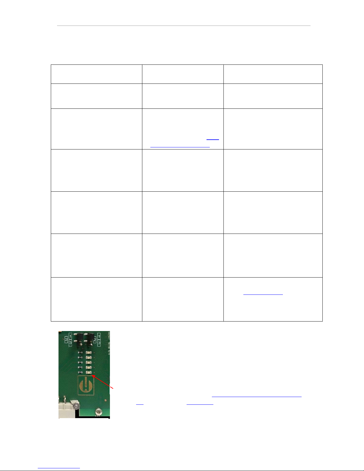
Error messages/troubleshooting
61
Further possible errors
Error pattern
Possible causes
Solution, troubleshooting
measures
Current loop does not function
properly
Incorrect measurement val-
ue at the output or no current measurable
Load too large
The device does not function immediately after being switched on.
No display indication.
LEDs on control card flash
Hardware error or error after
firmware update, depending
on the LED code shown.
See following section "Error
messages after self-test"
If an SD card has been inserted,
these notifications are stored in text
form in the error log – even when
the error recording function is not
active.
The device does not function immediately after being switched on.
No display indication.
Red and yellow LEDs next to the
SD card flash alternately.
Firmware update starts, but
no SD card has been inserted
Insert the SD card with the firm-
ware file and switch on the device.
The device does not function immediately after being switched on.
No display indication.
Two red LEDs on the control card
flash quickly
Firmware update starts, but
no firmware file was found
on the inserted SD card
Download the firmware file from the
Heyl website and copy the file onto
the SD card.
Device does not function, even
though it is switched on.
No display indication
All three green LEDs on motherboard light up*
Ribbon cable detached from
display board or motherboard
Error on display- or mother-
board
Plug ribbon cable back in
Replace display- or motherboard
Device does not function, although
it is switched on
No display indication
Fewer than three green LEDs on
the motherboard light up*
No power supply
Fuses on the power supply
board defective
There is no power supply.
See Replacing fuses
* For position of the LEDs, see illustration on page 69
Error messages after self-test
When switched on, the Testomat® EVO TH performs a self-test automatically and then monitors its own state continuously. If the LEDs
on the control card flash quickly after switching on, one of the above
errors has occurred and can be identified by the LED signal.
In addition, the error message is placed on the SD card in the error
log, even when the "Store error" function is inactive.
LED1
Control card
Page 62
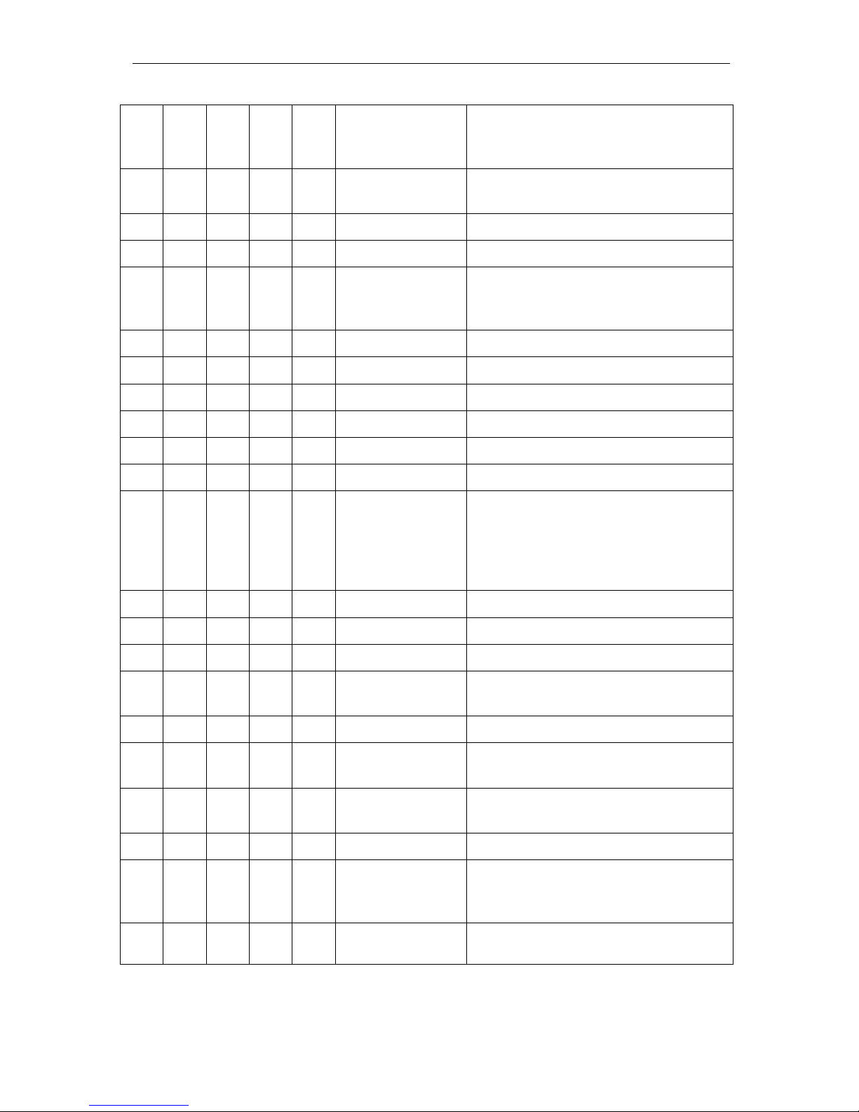
Error messages/troubleshooting
62
LED1
LED2
LED3
LED4
LED5
Error number/text
in alarm log on SD
card
Solution, troubleshooting measures
☼ ○ ○ ○ ○
500 CTRL-FRAM
IC2
1. Defective component. Repair/exchange
required.
☼
501 MB-IC12
See 1.
☼ ☼ ○ ○ ○
502 HMI-IC1
See 1.
○ ○ ☼ ○ ○
503 HMI-IC2
2. Loose cable between motherboard and
display?
If not: Defective, repair required.
☼ ☼ ○ ○
504 HMI-IC5
See 2.
○ ☼ ☼ ○ ○
505 MB-IC2
See 1.
☼ ☼ ☼ ○ ○
506 MB-IC5
See 1.
○ ○ ○ ☼
507 MB-IC3
See 1.
☼ ○ ○ ☼
508 MB-IC4
See 1.
○ ☼ ○ ☼
509 MB-IC6
See 1.
☼ ☼ ○ ☼
510 Font file
3. Character set or menu language could
not be read.
Internal SD card inserted and locked?
If yes, perform firmware update again. If the
error persists, a repair is required.
○ ○ ☼ ☼
511 Font info
See 3.
☼ ○ ☼ ☼
512 Font char
See 3.
○ ☼ ☼ ☼
513 Language file
See 3.
☼ ☼ ☼ ☼ ☼
514 Language
header
See 3.
☼
515 Language info
See 3.
☼ ☼
516 Menu entry not
found
See 3.
☼ ☼
517 Language magic
See 3.
☼ ☼ ☼
518 Fifo overflow
Software error. Firmware update required.
☼ ☼
519 DAC Calibration
invalid
Calibration of the DAC of the 20mA current
loop is invalid. Device must be recalibrated
in the factory.
☼ ☼ ☼
520 Wrong firmware
Wrong firmware for this device, install correct
firmware
☼ : Rapidly flashing LED (around 10 Hz). LED1 is below or next to
the plug connector to the motherboard.
Page 63
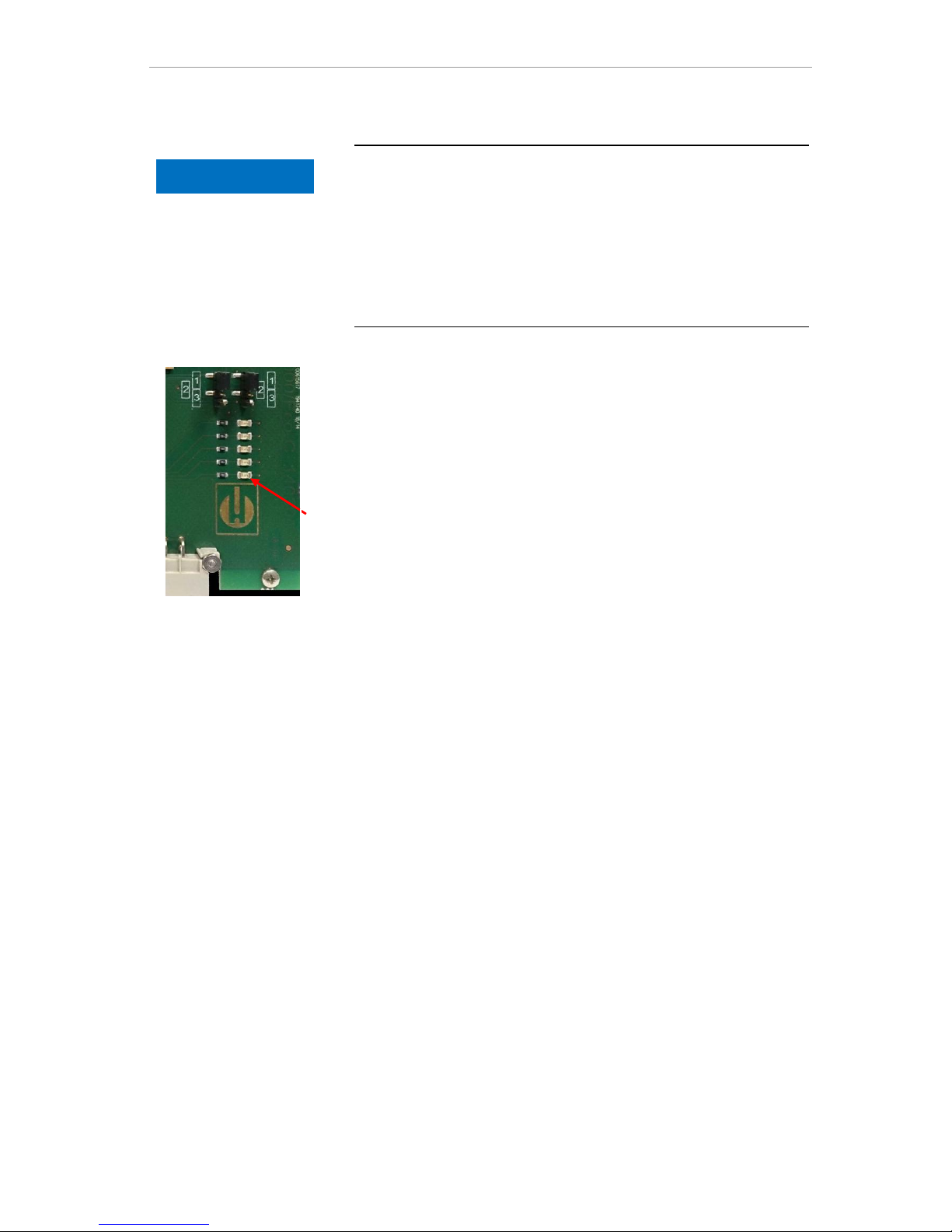
Error messages/troubleshooting
63
Firmware update error list
Has any firmware update error or error occurred after the selftest?
This error can be distinguished using the red LED next to the SD card
(see figure on page 51Fehler! Textmarke nicht definiert.Fehler!
Textmarke nicht definiert.):
If the LED lights up, the bootloader is active and the error concerned
occurred during the firmware update.
If the LED is inactive, it is an error after the self-test.
The error category is based on the number of simultaneously flash-
ing LEDs on the control card (for the precise error description,
please refer to the following table):
All five LEDs flash quickly: SD card cannot be read. Replace
card. If the attempted replacement fails, there is a defect on the
control card. Contact customer support; the device must be re-
paired.
Three or four LEDs flash quickly: Defect on the control card.
Contact customer support; the device must be repaired.
Two LEDs flash quickly: The file for the firmware update was
found, but is invalid or defective. Re-download the file.
One LED flashes quickly: Problem with SD card (Write protec-
tion, formatting).
For the Testomat® EVO TH, the filename should correspond to the
following format: "100M001S00.UPD", where 001 is the version
number, which increases incrementally as new versions are re-
leased.
LED bars not extended: They revert to the original configuration
after some time has elapsed and start from scratch: The means
that during the programming, an error was detected and an at-
tempt was made to resolve the error by repeating the update pro-
cess. The entire programming process is repeated up to five times.
For each repeat, the entire programming process is relaunched
from the start, whereupon the LED bars "emerge".
If, after five attempts, it is still impossible to perform any successful
update, the LEDs show an error corresponding to the list on the
following page. The device or the control card requires repair.
Please also send – particularly in this case – the content of the log
file on the SD card "update.txt" with the item or enclose the SD
card with the device.
Under normal cases, a firmware update is completed within 70
seconds.
NOTE
LED1
Control card
Page 64
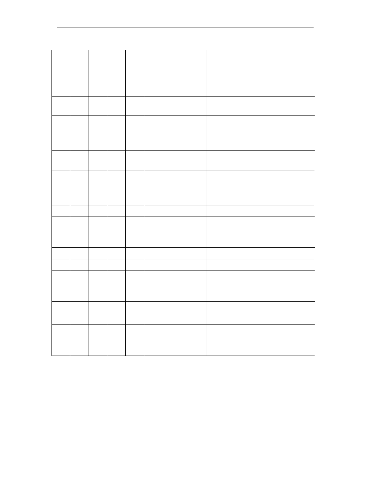
Error messages/troubleshooting
64
LED1
LED2
LED3
LED4
LED5
Error number/text
in update.txt
On SD card
Solution, troubleshooting measures
☼ ○ ○ ○ ○
900 No SD-Card inserted
Insert SD card, restart firmware update
○ ☼ ○ ○ ○
901 SD-Card write
protect
Confirm write-protect tab on the side of
the card, restart firmware update
☼ ○ ○
902 SD-Card init. failed
Re-insert SD card, restart firmware update.
In the event of multiple failures, a defect
is present and repair is required.
○ ○ ☼ ○
903 SD-Card unformatted
Format SD card, restart firmware update
☼ ☼ ☼ ☼ ☼
904 SD-Card read
error
Inserted SD card defective. Initially replace card.
If the defect persists, even after the replacement: Repair
☼ ☼ ☼ ☼
905 PCB SD read error
Internal micro SD card defective: Repair
☼ ☼ ☼ ☼
906 PCB SD write
error
Internal micro SD card defective: Repair
☼ ○ ☼ ☼ ☼
907 PCB SD init failed
Internal micro SD card defective: Repair
☼ ☼ ○ ☼ ☼
908 FRAM read error
Read error in internal I²C FRAM: Repair
☼ ☼ ☼ ☼
909 FRAM write error
Write error in internal I²C FRAM: Repair
☼ ☼ ☼
910 Flash control busy
Initialization error STM32 Flash: Repair
○
○☼ ☼ ☼
911 Flash program
error
Programming error STM32 Flash: Repair
☼ ☼ ☼
912 Flash write protect
Write protection STM32 Flash: Repair
☼ ☼ ☼
913 Flash timeout
Timeout STM32 Flash: Repair
☼ ☼
914 UPD file invalid
Invalid update file. Re-download
☼ ☼
915 UPD sec invalid
type
Section in update file defective: Redownload
☼ : Rapidly flashing LED (around 10 Hz). LED1 is below or next to
the plug connector to the motherboard.
Page 65
Error messages/troubleshooting
65
LED1
LED2
LED3
LED4
LED5
Error number/text in
update.txt on SD card
Solution, troubleshooting measures
☼ ☼
916 UPD sec invalid
start
Start info in update file defective: Redownload
☼ ☼
917 UPD sect invalid
len
Length info in update file defective: Redownload
☼ ☼
918 UPD CRC error
Checksum error in update file: Redownload
☼ ☼
919 UPD wrong version
Incorrect version of the update file:
Download the correct file for the appropriate device
☼
920 File not found
Update file on SD card not found: Recopy ☼ ☼ 921 App invalid
Application invalid
☼ ☼
922 App address invalid
Application start address invalid
☼ ☼
924 No language file
Language file missing: Reprogram with
new update file
☼ ☼
925 Language magic
wrong
Language file missing: Reprogram with
new update file
☼ ☼ ☼
926 Error mem alloc
Storage error: Repair
☼ ☼ ☼
927 Assertion failed
Software error: Repair
☼ ☼ ☼
928 Unknown error
Unknown error: Contact support department, repair
☼ : Rapidly flashing LED (around 10 Hz). LED1 is below or next to
the plug connector to the motherboard.
Page 66
Servicing and maintenance
66
Servicing and maintenance
Required maintenance measures
To ensure problem-free function of the device, regular mainte-
nance is required!
Before sending the device in for maintenance or repair, package
the power pack individually in the original box in which it was deliv-
ered. If the original packaging is no longer available, package the
device to prevent breakage.
Ensure at least the following specified maintenance work is performed regularly, if
The device shows the following error messages:
" 35 Fault soiling" or " 37 Indicator low"
The most recent maintenance was a maximum of six months earli-
er
Description of the maintenance work
A detailed description of the maintenance work can be found in the
maintenance manual. The measures described here only constitute
an overview. For all additional maintenance instructions, please refer
to the Testomat® EVO TH maintenance manual.
Cleaning measures
Never use organic solvents to clean the measuring chamber and
other plastic parts!
Observe the safety instructions when handling cleaning agents!
If the measurement scope of the device is exceeded for an ex-
tended period, this may result in the formation of a colored film on
the viewing window. This firmly adhering film can be easily re-
moved using alcohol.
Replacing indicator
Replace the indicator as follows:
Open the lower housing door by pulling on the right side
Unscrew the closing cap of the indicator bottle and remove the
empty indicator bottle. Continue with the Insertion of the indicator
bottle, as described in the commissioning section and the subse-
quent Resetting of the indicator fill level.
CAUTION
!
NOTE
Page 67
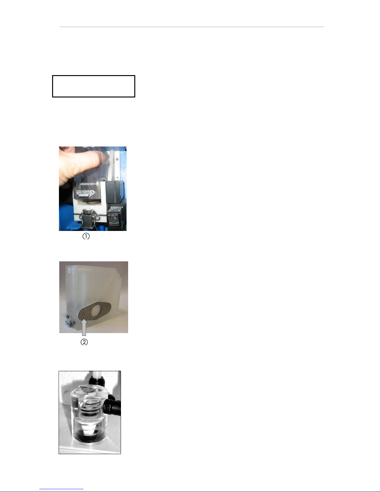
Servicing and maintenance
67
Setting indicator fill level
The indicator fill level must be set when refilling the indicator bottle
set or reset during a replacement.
Select the menu
=> Service => Reagent => Filling level
100%
With "OK”, the current fill level is reset to 100 percent.
If only the fill level should be reset, confirm the fill level with "OK
or.
Change the value of the fill level with the cursor keys and subse-
quently confirm with "OK".
Cleaning of the measuring chamber and the viewing windows
Cleaning interval: ¼ yearly
Switch off the device or press the "Pause" button
Check that the measuring chamber is completely emptied.
Connect the manual valve of the secondary line to the Testomat®
EVO TH.
Release the spring lock, tilt the measuring chamber upwards and
take it out.
Remove both the viewing window holders and then remove the
viewing windows for cleaning.
Remove the film on the viewing windows with alcohol.
Clean the measuring chamber with 10 percent hydrochloric acid
and then rinse it thoroughly.
Reinsert the viewing windows after cleaning and fix them in place
with the viewing window holders
Do not forget to insert the O-ring seals and be careful to ensure
correct fitting in the groove.
Put the measuring chamber back in place by tilting the unit and
secure it with the spring lock.
Cleaning the filter housing
Cleaning interval: ½ yearly
Connect the manual valve of the secondary line to the Testomat®
EVO TH.
Press the "Pause" button and wait until the current measurement
has finished.
Release the piping system of the Testomat® EVO TH with the func-
tion Internal flush manually.
Switch off the device.
Remove the hose connections on the filter housing.
Unscrew the supply nozzles.
Remove and clean the seal, spring and filter.
REAGENT
Filling level 100%
Page 68
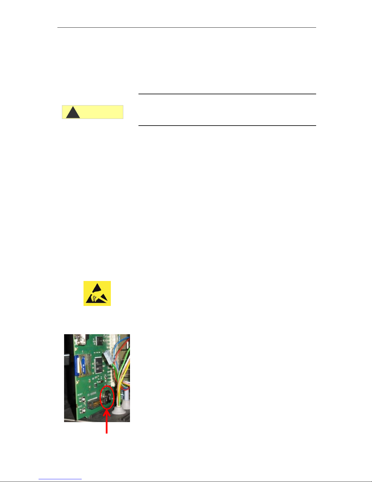
Servicing and maintenance
68
Remove the locking pin and pull it out of the flow regulator.
Remove the flow governor core.
Clean the filter housing with water or alcohol and reconstruct it.
Ensure that you insert the filter sieve with the top facing down!
Attach the hose connections to the filter housing.
Observe the following during maintenance measures
Water ingress at the sealing points may lead to the device components being damaged!
Leak resistance test
Perform a leak resistance test before the first analysis:
Switch the device to "Pause".
Fill the measuring chamber during manual operation
Measure out the indicator dose by hand. To do so, press the
"Manual" button on the dosing pump.
Check the connections and sealing points for leakage.
Care instructions
The surface of the device is untreated. Avoid therefore any soiling
with indicator, oil or grease. However, if the housing is soiled, clean
the surface with isopropyl alcohol (never use any other kind of solvent).
Replacing the backup battery
When the device is switched off the internal clock is powered by a
lithium backup battery (CR2032 type), which is designed to have a
service life of 10 years. After this period, it should be replaced for
preventive reasons, and always ensuring a measured voltage <2.3V.
The following is required when replacing the battery
A Phillips-tip screwdriver
A replacement battery CR 2032
Replace the battery as follows:
Switch off the device and disconnect it from the power supply
Open the upper housing door
CAUTION
!
Observe ESD safety
precautions! See the
information on page 8
Page 69
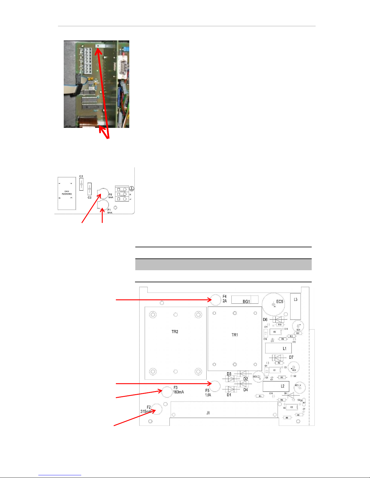
Servicing and maintenance
69
Remove both fixing screws of the upper and lower control card
on the motherboard
Remove the control card
Using a non-conductive tool, carefully prise the used battery out of
its mounting. Avoid damaging the circuit board with the sharp edge
of a screwdriver.
Insert a new battery
Reconstruct the circuit board by following the steps for dismantling
of the same in reverse.
Replacing fuses
Device fuses (internal)
These fuses protect the Testomat® EVO TH device or outputs
against overload and short circuit. All fuses are pluggable.
The main fuses F1 and F6 (4A MT) for outputs and equipment are
located on the motherboard.
The power pack includes the four primary and secondary fuses, F2 to
F5 for 24V and 12V, 3.3V
Circuit board for power pack 230V
24V
12V/3.3V
Primary
F2: 315 mA/T
F3: 160 mA/T
Secondary
F4: 2 A/T
F5 1.6 A/T
F4
F5
F3
F2
Motherboard
F1
F6
Page 70
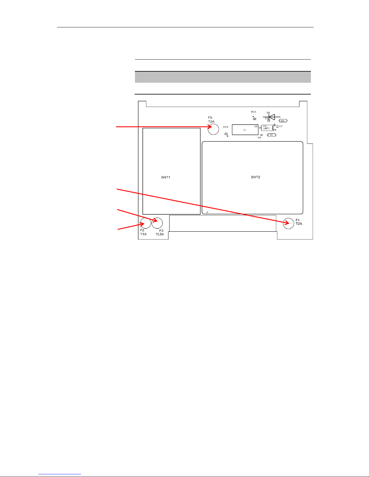
Servicing and maintenance
70
Multi-range power supply board 100 – 240V
24V
12V/3,3V
Primary
F2: 1 A/T
F3: 0.5 A/T
Secondary
F4: 2 A/T
F5: 2 A/T
F5
F4
F3
F2
Page 71
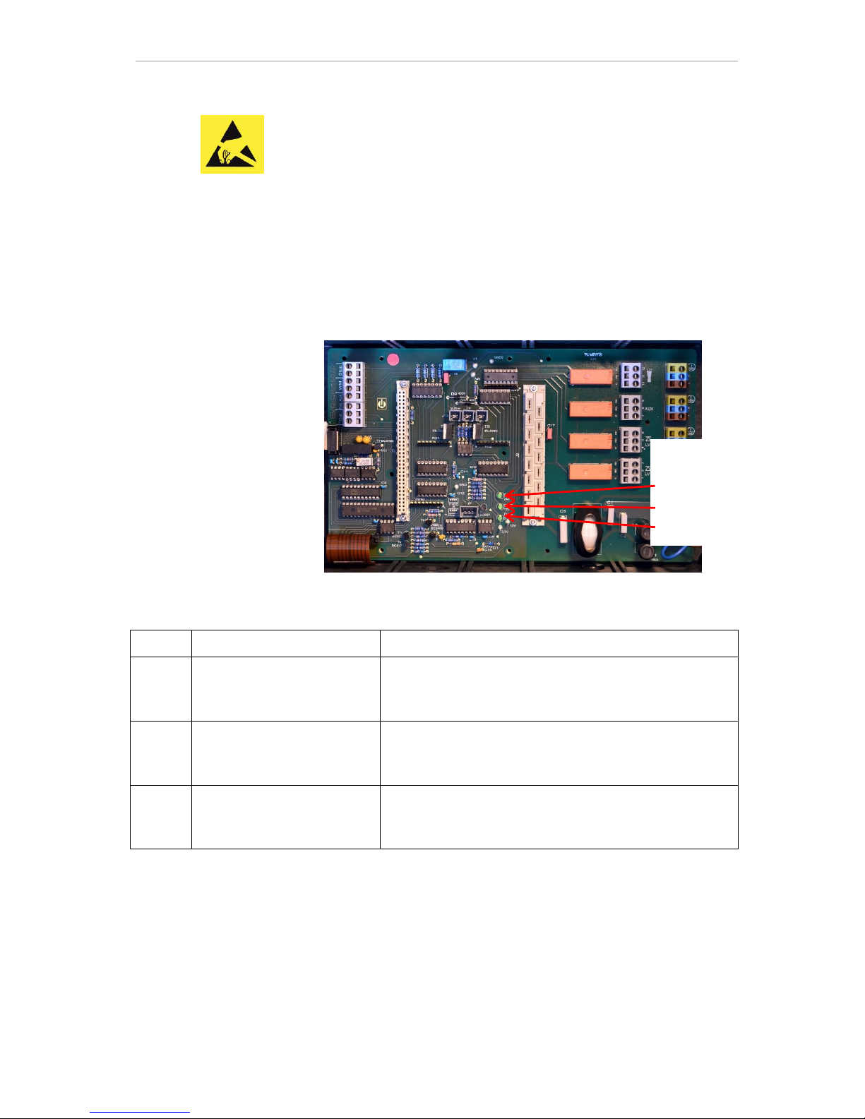
Servicing and maintenance
71
Exchange
If not all three green LEDs on the motherboard light up, at least one
fuse is defective. The supply voltage unit is next to the LED, which
indicates its status.
You require:
A Phillips-tip screwdriver
Flat-tip screwdriver
Replacement fuses
To find the defective fuse, proceed in accordance with the troubleshooting scheme.
Troubleshooting scheme:
Step
LED / lamps
Action
1
Open up the device at the top
and switch it on. Does at least
one LED light up?
No → Step 2
Yes → Steps 5, 6
2
Does the power supply work
and is a permissible voltage
measured between N and L?
No → Service
Yes → Step 2a
2a
Is the voltage measured in
step 2 also measured between n and l?
Yes → Step 4
No → Step 3
Green LEDs on the
motherboard:
24V
12V
3.3V
Observe ESD safety
precautions! See the
information on page 8
Page 72

Servicing and maintenance
72
Step
LED / lamps
Action
3
Primary fuse F1 od F6 on the
motherboard defective.
Disconnect device from the mains!
Remove cable compartment cover (Phillips-tip screwdriver).
Use a flat-tip screwdriver to turn and rotate the safety cover.
Replace safety fuse 4A
Put safety cover back in place.
When switching on the Testomat device, check whether all
three green LEDs light up. Otherwise, restart from Step 1.
4
Fuses on the power supply
board defective.
Disconnect device from the mains!
Remove both fixing screws of the upper and lower power
supply board on the motherboard.
Remove the power supply board.
Change the plug-in fuses F2, F3, F4 and F5.
Re-insert the power supply board.
Assemble both fixing screws
When switching on the Testomat device, check whether all
three green LEDs light up. Otherwise, restart from Step 1.
5
3.3V + 12 V do not light up
Disconnect device from the mains!
Remove both fixing screws of the upper and lower power
supply board on the motherboard.
Remove the power supply board.
Change the plug-in fuses F5 (T1,6A) and F3 (T0,16A).
Re-insert the power supply board.
Assemble both fixing screws
When switching on the Testomat device, check whether all
three green LEDs light up. Otherwise, restart from Step 1.
6
24V does not light up
Disconnect device from the mains!
The fuse F4 is located at the top edge of the power supply
board. Change the plug-in fuse F4 (T2A).
When switching on the Testomat device, check whether all
three green LEDs now light up. Otherwise, F2 (T0,315A)
must also be changed:
Remove both fixing screws of the upper and lower power
supply board on the motherboard.
Remove the power supply board.
Change the plug-in fuse F2 (T0,315A).
Re-insert the power supply board.
Assemble both fixing screws
When switching on the Testomat device, check whether all
three green LEDs light up. Otherwise, restart from Step 1.
Page 73
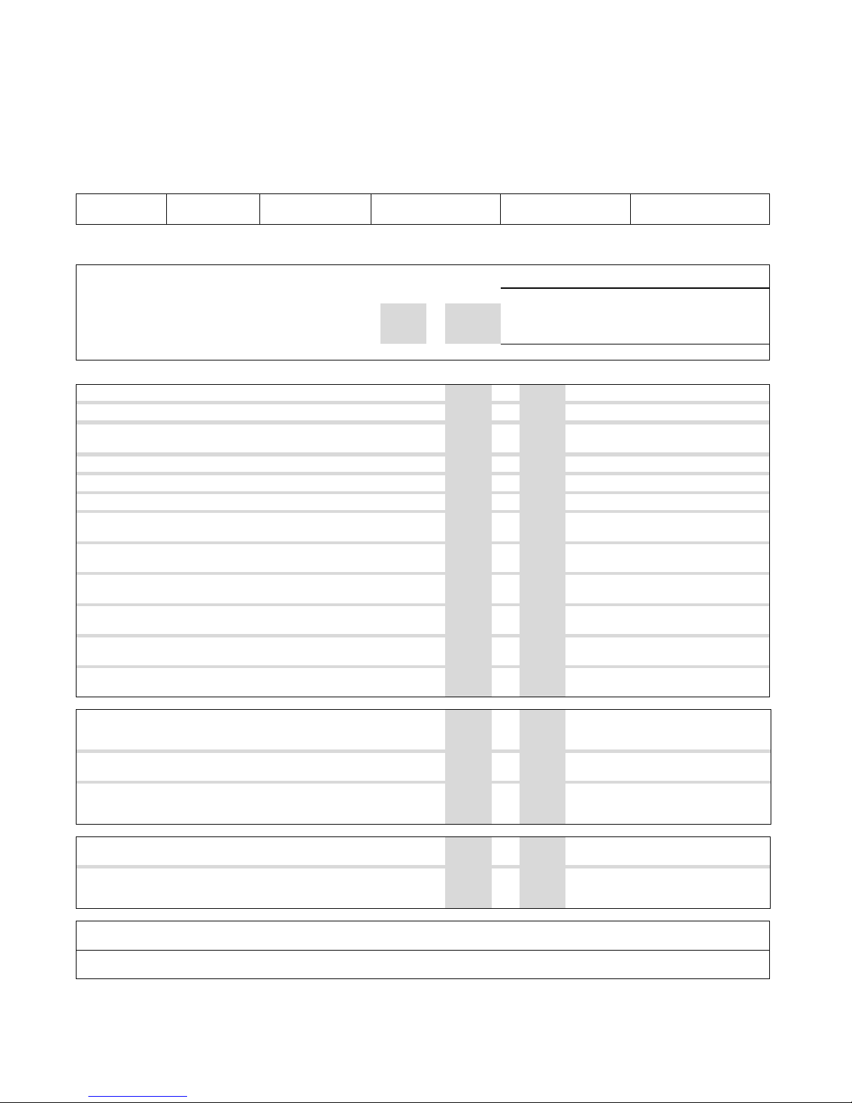
Checklist Testomat® EVO TH
Dear customers and service technicians,
The following checklist is no substitute for your expertise and experience applied to the process of troubleshooting. It should assist you and facilitate
swifter and more systematic detection and logging of errors. No claim of completeness may be inferred from this list. We are grateful to receive
supplementary feedback at any time. General operating instructions are included on the rear of this checklist.
Your device manufacturer
Block 1 / System and device data
Testomat® EVO
TH
System type
Device type
Device number
Indicator type
Software version
Pump No.
Block 2 / error message and error history Please place a cross as appropriate (X)
What does the error history of the device indicate?
( Text of the error history )
Does an error message appear on the display?
e.g. "Water low" etc. (See instruction manual "Error messages
/ Help dealing with faults")
Yes No
( Text of the error message )
Block 3 / Visual and functional check Please place a cross as appropriate (X) where applicable values / comments
Is the mains voltage for the device in accordance with the type plate?
Yes No
Does an indicator appear on the display?
Yes No
Do the three green LEDs light up to indicate the stresses on the motherboard?
Yes No
Do LEDs flash on the control card?
Yes No
Which LED?
Are the measuring chamber and hoses carrying water leakproof?
Yes No
Is the measuring chamber clean and free of film?
Yes No
Has the correct indicator type been programmed in?
( TH 2025 => 0.25 up to 2.5 °dH = Factory default )
Yes No
Type:
Is the water pressure in the stipulated range (400 ml/min)?
(See type plate of the device)
Yes No
System pressure:
Is the outflow over the entire length laid to ensure no back pressure?
(No "siphon effect"!!)
Yes No
Is the drain hose free?
(Micro-organisms due to contamination etc.)
Yes No
Is the purge cycle / rinsing water quantity set such that
Fresh water can always be measured?
Yes No
Purge cycle:
Are the hoses to the dosing pump free of air bubbles?
(Operate pump by hand / Perform manual analysis)
Yes No
PERFORM A (MANUAL) ANALYSIS
Does the water level rise uniformly when filling the measuring chamber up to
the overflow hole (5 mm under the top edge of the measuring chamber)?
(If no: check water pressure, water flow/flow regulator)
Yes No
Does the indicator pump dose when an analysis is triggered?
(LED on the pump comes on!)
Yes No
Number of dosing strokes:
After the dosing process, is the indicator correctly mixed with the water in
the measuring chamber?
Check the stirrer! => See maintenance manual "Alignment operation"
Yes No
PROGRAMMING DATA / OPERATING CONDITIONS
Are the configured limit values correct? (Within the measurement
range/corresponding to the performance limit of the system?)
Yes No
Limit values:
Is the Testomat continually supplied with mains voltage – except during
maintenance work/emergency cases?
(Intermediate switching off only with "PAUSE" button or "Stop”! input)
Yes No
More details of error messages and possible causes of errors can be found in the operating instructions under "Error messages / Help dealing
with faults".
Further functional tests (e.g. overflow detection and gain adjustment => "Special function alignment operation") and service indications can be
found in the maintenance manual.
After performing these tests, experience supports the assumption that the checked functions (Block 3) work flawlessly if the questions are answered
with "Yes". We recommend carrying out these tests systematically during each inspection or any disruptions which arise.
Page 74
74
Device settings for Testomat® EVO TH
Caution!
Your settings may be deleted in the event of a repair. Accordingly, export your device settings onto an SD card before sending the
device for repair to our service team. The settings can be re-imported after the repair.
Menu
Setting
MODE OF OPERATION
Time controlled
Volume interval
Volume and time
INTERVAL
Time
Volume
BOTTLE SIZE
500ml bottle
100ml bottle
TYPE OF REAGENT
Type TH2005
Type TH2025
Type TH2100
Type TH2250
DISPLAY OF UNIT
Display °dH
Display °f
Display ppm CaCO3
Display mmol/l
LIMIT VALUES
LV1: LV2:
FLUSH TIME
Flush
ExceedanceFlush
WATER METER
1 l/Impulse
2,5 l/Impulse
5 l/Impulse
10 l/Impulse
100 l/Impulse
500 l/Impulse
1000 l/Impulse
Imp./L
BOB
Function on
FUNCTION LV1/LV2
Limit value
Two point
Range
RELAY LV1
Hysteresis LV1
Duration
Impuls
Interval
Time:
RELAY LV2
Hysteresis LV2
Duration
Impuls
Interval
Time:
RELAY AUX
Before retry
Before analysis
During analysis
Before + during analysis
After analysis
Time
WATER LOW COUNT
Count
FUNCTION STOP
Normally closed
Normally open
FUNCTION WM
Normally closed
Normally open
EXTERN ACK.
Normally closed
Normally open
CURRENT INTERFACE TYPE
Type 0-20 mA
Type 4-20 mA
SERIAL INTERFACE
Baudrate
LCD SETTINGS
Brightness
Contrast
FUNCTION SD CARD
Store measurement
Store error
Import basic data
Export basic data
SERVICE TIME
Interval
LANGUAGE
English
German
Français
Nederlands
Espanol
Türkçe
中文
Czech
Page 75
Spare parts and accessories for Testomat® EVO TH
75
Spare parts and accessories for
Testomat
®
EVO TH
Art. No
Pressure regulator
40125
Controller / filter mounting, complete
40120
Controller / filter mounting
40129
Controller plug T2000, complete
11225
Flow governor core complete
11230
Locking pin 3x38 / 90 degrees
11217
Filter sieve for inflow 19.5dx25
11218
Spring for inflow
40121
Inlet connection
40153
Male connector G 1/4" -6
40157
Angle male connector G 1/8"
Measuring chamber
40173
Viewing window with seal, T2000
40170
Viewing window 30x3
40176
Viewing window holder, vertical and
weighted
33253
Screw M3x40, A2, DIN 965
40032
Tensioning hook TL-17-201-52
11203
Disk plug 5.3dx5 PE natural
40022
Measuring chamber T2000 complete
Measuring chamber mounting
40029
Measuring chamber mounting complete
ET
40050
Stirrer
40157
Male connector 3/8" -10, processed
34620
Magnetic valve, 2/2 ways, Testomat®
EVO TH
DosiClip® dosing pump
270470
DosiClip dosing pump
40011
Hose, suction, complete
40016
Hose, pressure, complete
40040
Valve set
32046
Covering hood CNH 45 N
Bottle connection/suction device
40131
Screw cap with Insert T2000
40130
Screw cap GL32 - hole
40135
Insert for screw cap with suction pipe
Art. No
Device spare parts
31582
Fuse GS-M 5x20E 4A MT
31655
Fuse T2A (24V)
12140
Fuse T1.6A (12V/3.3V)
31622
Fuse T0.16A
31585
Fuse T0.315A
32383
Motherboard complete 230V
32387
Controller board complete
32385
Display circuit board EVO complete
37734
Cable ducting M16 x 1,5
37735
Nut for cable ducting M16 x 1,5
37736
Blanking plug for cable ducting
31713
Ribbon cable 10 pol. with ferrite
31656
Jumper
40060
Cable harness 2V for T2000
40062
Cable harness 2P for T2000
37320
Standard SD card 2 GB
31999
Lithium backup battery CR2032
32391
Multi-range power supply board 100V –
240V
32390
Power supply board 230 V
32187
Drain funnel
Spare parts required for 2 - 3 years of opera-
tion
40173
Viewing window with seal, T2000
11217
Filter sieve for inflow 19.5dx25
40124
Seal kit T2000
Page 76
Spare parts and accessories for Testomat® EVO TH Accessory
76
Accessory
Indicators
Indicator
type
Range
Quantity
Art. No.:
TH2005
Water hardness 0.05 - 0.5 °dH
500 ml
152005
TH2005
Water hardness 0.05 - 0.5 °dH
100 ml
151005
TH2025
Water hardness 0.25 - 2.5 °dH
500 ml
152025
TH2025
Water hardness 0.25 - 2.5 °dH
100 ml
151025
TH2100
Water hardness 1.0 - 10.0 °dH
500 ml
152100
TH2100
Water hardness 1.0 - 10.0 °dH
100 ml
151100
TH2250
Water hardness 2.5 - 25.0 °dH
500 ml
152250
TH2250
Water hardness 2.5 - 25.0 °dH
100 ml
151250
Additional accessories
*) Conversion kit for water intake, Art. No. 040123
When using fabric pressure hoses (e.g. for existing installations),
please replace the plug connection on the controller and filter housing
for a plug for the quick-release coupling (not included in the delivery
scope).
A current device overview of the available accessories can be found
in details of our delivery scope.
Art. No.
Designation
040187
Connector set: Cock, hoses, reducers
130010
Mini irrigator type R for Testomat devices
270352
Service set including flow controller
270410
MepuClip booster pump
100490
Standard SD card 2GByte
040123
Conversion kit for water intake *)
270337
Maintenance case T2000 Heyl
100491
WLAN SD card 8GByte
Page 77
Technical Data
77
Technical Data
Power supply:
230 VAC or 100 – 240 VAC
± 10%, 50 - 60 Hz
Complete protection T4A including user
power supply
Power consumption:
max.
without external load
230V (100-240V) / 4A
230V (100-240V) / 1A
Protection class:
I
Protection type:
IP 44
Conformity:
EN 61326-1, EN 61010-1
Ambient temperature:
10 – 40°C
Measuring range:
See section "Service description"
User power supply:
Switched power supply with 4A fuseprotected
Durability relay:
DC: 8A at 30V or 0.28A at 250V
AC: 8A at 415V
Current loop:
0/4 - 20 mA
Maximum load 500 ohm corresponding to
10V voltage, voltage isolated
SD card interface:
For SD and SDHC cards up to max.
32GByte, FAT/FAT32 formatting
WLAN:
Optional including WLAN SD card in the
accessories
Dimensions:
W x H x D = 380 x 480 x 280 mm
Weight:
Around 9.0 kg
Other:
The device is power-failure protected
Water connection
Working pressure:
1 to 8 bar / 1x10⁵ to 8x10⁵ Pa
or
0.3* to 1 bar / 0.3x10⁵ to 1x10⁵ Pa
(after removing the valve body)
Water intake:
Opaque pressure hose with external diameter 6/4x1 mm
Water drain:
Hose with internal diameter 12 mm
Water temperature:
10 – 40°C
Properties
Water sample**
pH value >4
CO2 value < 20 mg/l
* When using the Testomat® EVO TH with an upstream pressure of
0.3 bar, it must be ensured that a minimum flow quantity of 400
ml/min can traverse the measuring chamber.
** see also notes on page 10
Page 78
Technical Data Equipment options
78
We reserve the right to make structural changes with continual
improvement in mind!
Our user manuals are regularly updated. If you have an older
version (see details of the version on the rear of the instructions), you can find the most recent version of the operating
instructions on our homepage www.heyl.de under Download.
Equipment options
You can select the following options for the Testomat® EVO TH:
Option
Description
Power supply
230 VAC
230 V – power supply
100-240 VAC /
100-353 VDC
Wide-range power supply
Plug-in card
W-LAN SD card
Wireless measured value enquiry via
W-LAN
Housing
available in blue or black
Page 79
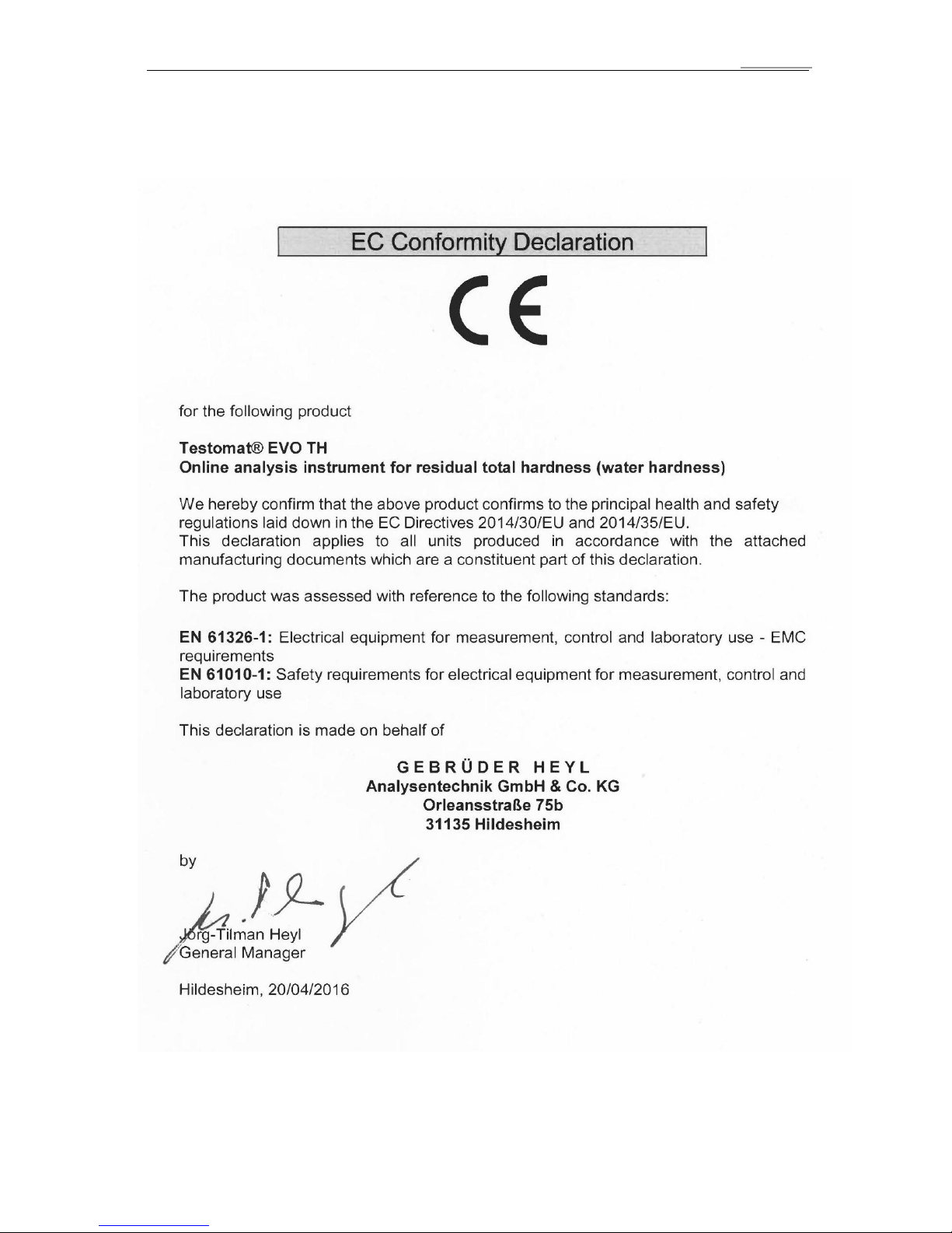
Declaration of conformity
79
Declaration of conformity
Page 80

NRTL certificate
80
NRTL certificate
Valid for devices with wide-range power supply 100 – 240V!
Page 81
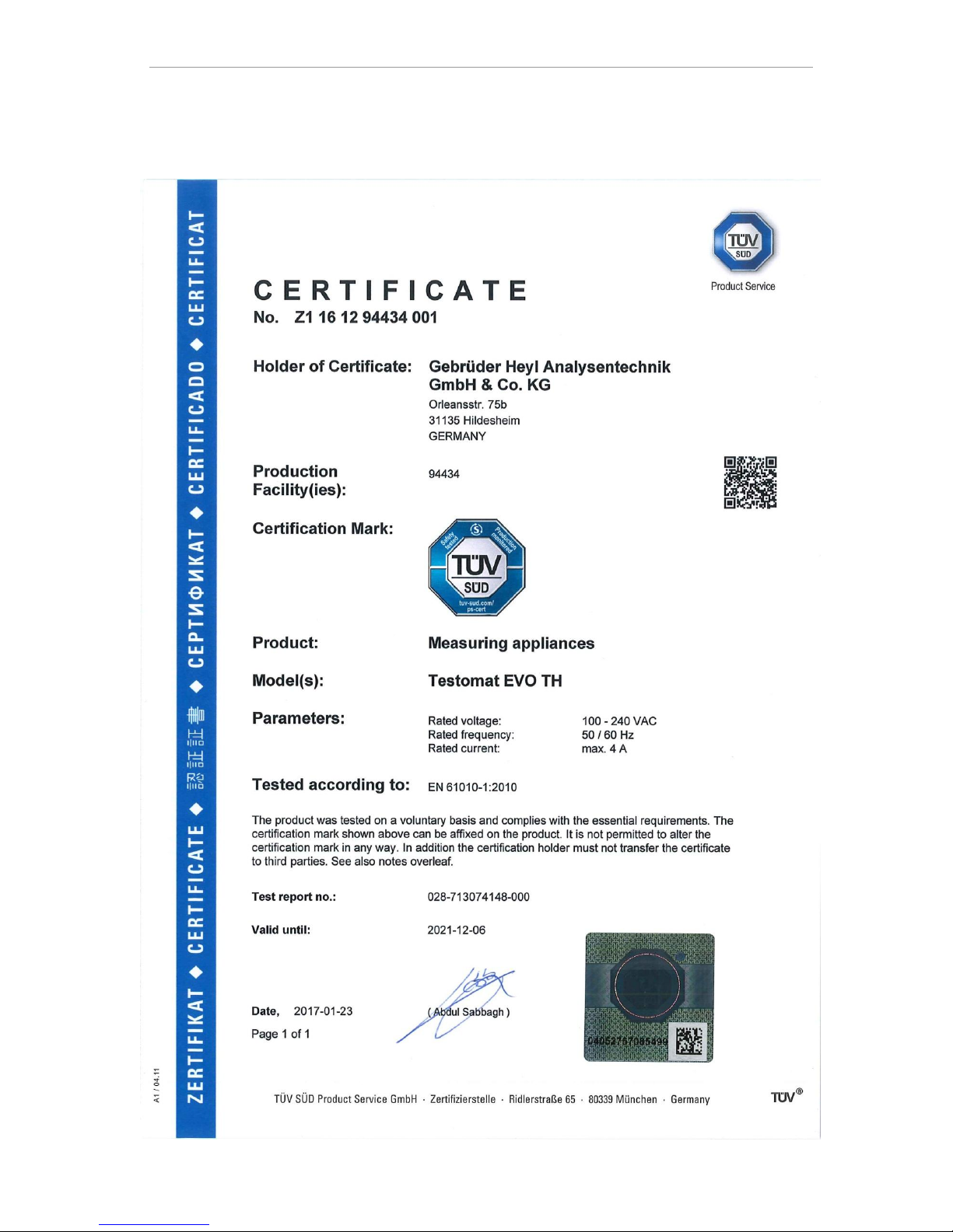
TÜV certificate
81
TÜV certificate
Valid for devices with wide-range power supply 100 – 240V!
Page 82
Gebrüder Heyl
Analysentechnik GmbH & Co. KG
Orleansstraße 75b
D 31135 Hildesheim
www.heyl.de
Testomat_EVO_TH_GB_181106.docx
Scan the code and
visit us on our homepage!
 Loading...