

Page 1
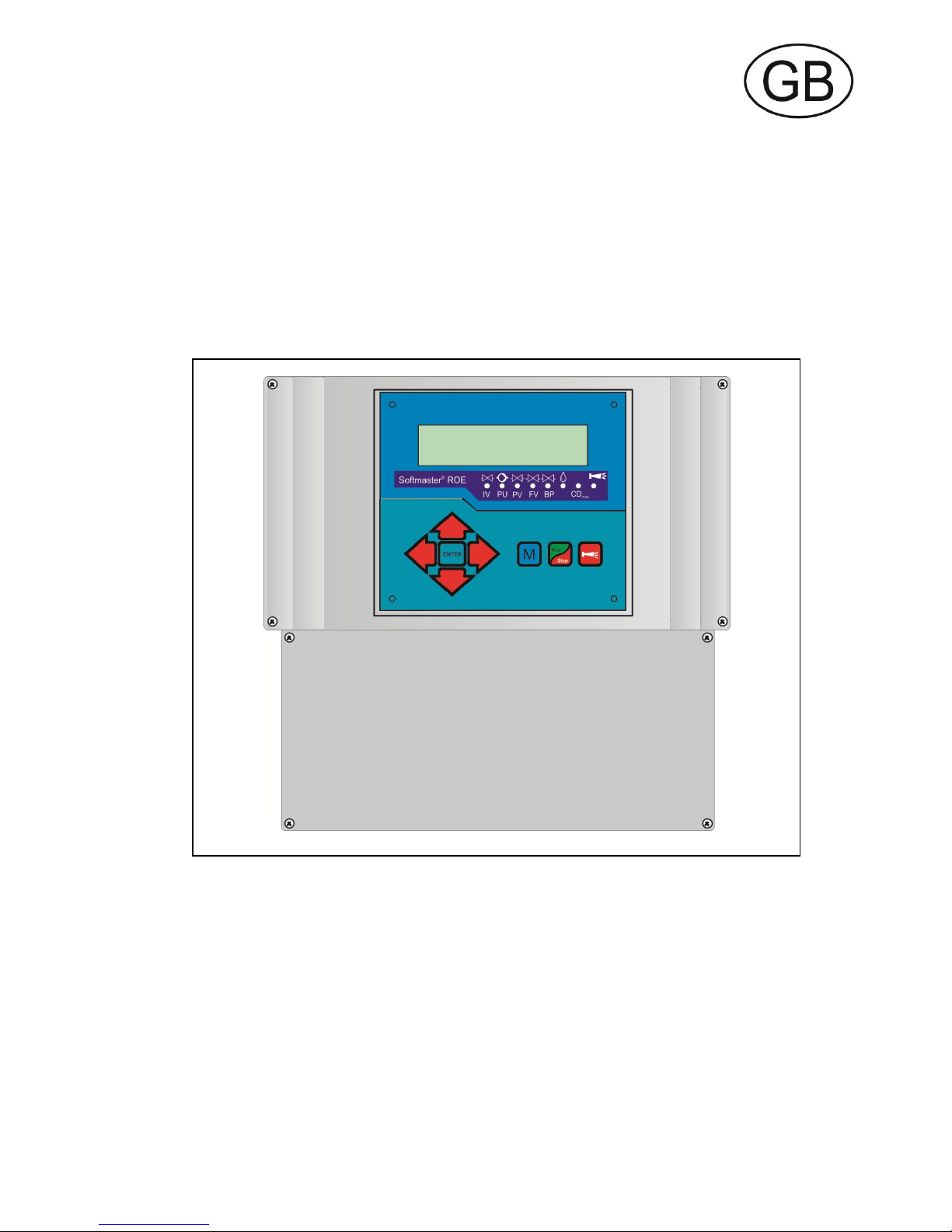
Softmaster7 ROE 2
Microprocessor controllers for reverse osmosis plants
Operating instructions
Page 2

235
Table of contents
Table of contents................................................ 2
General notes ..................................................... 3
Introduction .................................................................. 3
Handling notes ............................................................. 3
Safety notes ................................................................. 3
Installation and commissioning .................................... 3
General description ............................................ 4
Views of unit ................................................................. 4
Description of display and operating features .............. 5
Display functions .......................................................... 6
LED displays ................................................................ 6
Operating displays ............................................. 7
Error messages .................................................. 7
Terminal block identification ........................... 11
Functions (IN = input, OUT = output) ......................... 11
Description of relay outputs ....................................... 13
PU1 / PU2, pressure pumps 1 and 2 ............................... 13
IV Input valve ................................................................... 13
FV Flush valve ................................................................. 13
PV Output valve (Permeate valve) .................................. 13
BP By-pass valve (emergency program) ......................... 14
PR programmable function output ................................... 14
AL Fault message output ("Alarm") ............................... 14
Description of signal inputs ........................................ 15
MP Motor protection ........................................................ 15
HL and LL High and Low level ......................................... 15
HP Excess pressure ........................................................ 16
LP Low water pressure .................................................... 16
STOP Switch off of the plant ............................................ 17
CO Concentrate monitoring ............................................. 17
PROG Programmable function input ............................... 17
CD1 Connection for conductivity sensor .......................... 18
PT100 Connection for temperature sensor PT100 .......... 19
OUT Interface .................................................................. 19
Functioning ....................................................... 20
Switching on and power failure ........................................ 20
Production / Run .............................................................. 20
Standby ........................................................................... 20
Flush after production ...................................................... 20
Interval flush .................................................................... 20
Quality flush and emergency service ............................... 20
Emergency program / By-pass ........................................ 21
Conductivity monitoring ................................................... 21
Programming .................................................... 22
Start menu.................................................................. 22
Menu selection ........................................................... 22
Input ........................................................................... 22
End menu .................................................................. 22
Information menu....................................................... 22
Programming ............................................................. 22
Enter password .......................................................... 22
Change password...................................................... 22
Flushing mode ........................................................... 22
Flushing duration ....................................................... 23
Interval flush .............................................................. 23
Quality flush ............................................................... 23
Probe CD1 Permeate ................................................ 23
LV Permeate Max., .................................................... 23
LV Permeate Min., ..................................................... 23
Temperature compensation ...................................... 24
LV Temperature ......................................................... 24
Function Pump .......................................................... 24
Function Low water pressure .................................... 24
Function Excess pressure ......................................... 25
Function Concentrate ................................................ 25
Function Motor protection .......................................... 25
Function Stop ............................................................ 25
Function PROG ......................................................... 25
Water meter ............................................................... 26
Metering ..................................................................... 26
Funct. IN 0/4-20mA input .......................................... 26
Function OUT PR output ........................................... 26
Interface ..................................................................... 26
Baud rate ................................................................... 26
Release ..................................................................... 27
Language ................................................................... 27
Serial number ............................................................ 27
ASERVICE@ menu ............................................... 27
Operating hours ......................................................... 29
Water meter ............................................................... 29
Pressure .................................................................... 29
Time/Date .................................................................. 29
Diagnosis ................................................................... 29
Software status .......................................................... 29
Menu structure .................................................. 30
Technical appendix ........................................... 31
Example for an osmosis plant layout ......................... 31
Connection example .................................................. 32
Connection example for 24 V .................................... 33
Conformity Declaration .............................................. 34
Technical Data ........................................................... 35
Page 3

335
General notes
Introduction
These operating instructions describe the installation, operation and programming of the reverse osmosis controller
Softmaster ROE 2.
We recommend that, whilst familiarising yourself with the operation of the unit aided by this manual, you have immediate
access to the operable controller in order to perform the functions and combinations as described. As certain functions
are interrelated, it is advisable to follow the instructions in the given order.
Should problems or questions arise which are not described in this manual and/or cannot be solved, our customer
service is always at your disposal.
Try to identify the problem as accurately as possible and record the conditions under which it occurred. This will enable
us to offer you swift effective assistance.
Handling notes
Quick, repeated switching on/off of the controller should be avoided. Wait at least 5 seconds before switching the unit
either 'on' or 'off' at the main switch.
Only operate the controller in compliance with the ambient conditions (e.g. temperature, moisture) stated in the chapter
entitled technical data. Especially protect the controller against moisture.
The controller should not come into contact with splash or condensation water.
Before dismantling a defect controller, always write down the description of the error (failure effect). Repair work
(independent of the guarantee period) is only possible after the unit has been dismantled and returned to us with a
description of the error.
The warranty shall not apply if the controller is tampered with, altered, modified or repaired contrary to the instructions
described in this manual.
The allowed maximum electrical load capacity of the relay outputs and the total power rating of the plant must not be
exceeded.
The controller should only be used for the stated intended purpose.
Safety notes
Always pay attention to the following safety notes:
Only connect the device to the mains voltage displayed on the type plate. The controller must be installed and operated
in compliance with the relevant standards (e.g. DIN, VDE, UVV), or in accordance with the regulations laid down by the
individual country.
Some functions (e.g. manual production) allow direct manipulation of the plant (valves, pumps, etc.), without locking or
monitoring. These functions are thus protected by a password and are only to be used by trained personnel.
If you observe malfunctioning of the controller, switch it off immediately and inform the service personnel.
Do not attempt to repair the controller yourself (loss of warranty rights); instead always get in touch with authorized
service personnel. This is the only way a reliable and safe operation of the plant can be ensured.
After protective equipment (safety fuse, motor protection circuit breaker) has been triggered, attempt, at first, to eliminate
the cause of the malfunctioning (e.g. clean the pump) before reactivating the protective equipment. Frequent triggering is
always due to an error which, in certain circumstances, may also cause damage to the controller.
Ignoring these notes can result in damage to the controller as well as the plant and may result in a loss of warranty rights.
Installation and commissioning
Installation as well as commissioning must only be undertaken by authorized technicians!
The connecting cables to the sensors should be kept as short as possible and clear of power cables. Close proximity to
strong electromagnetic radiators can lead to deviations of the display; in this case, separate interference suppression
measures should be carried out.
After installation, program the unit with the plant-specific features and data (e.g. switch functions, conductivity limit
values, etc.). The data is permanently stored (also during power failure).
Page 4
435
General description
Views of unit
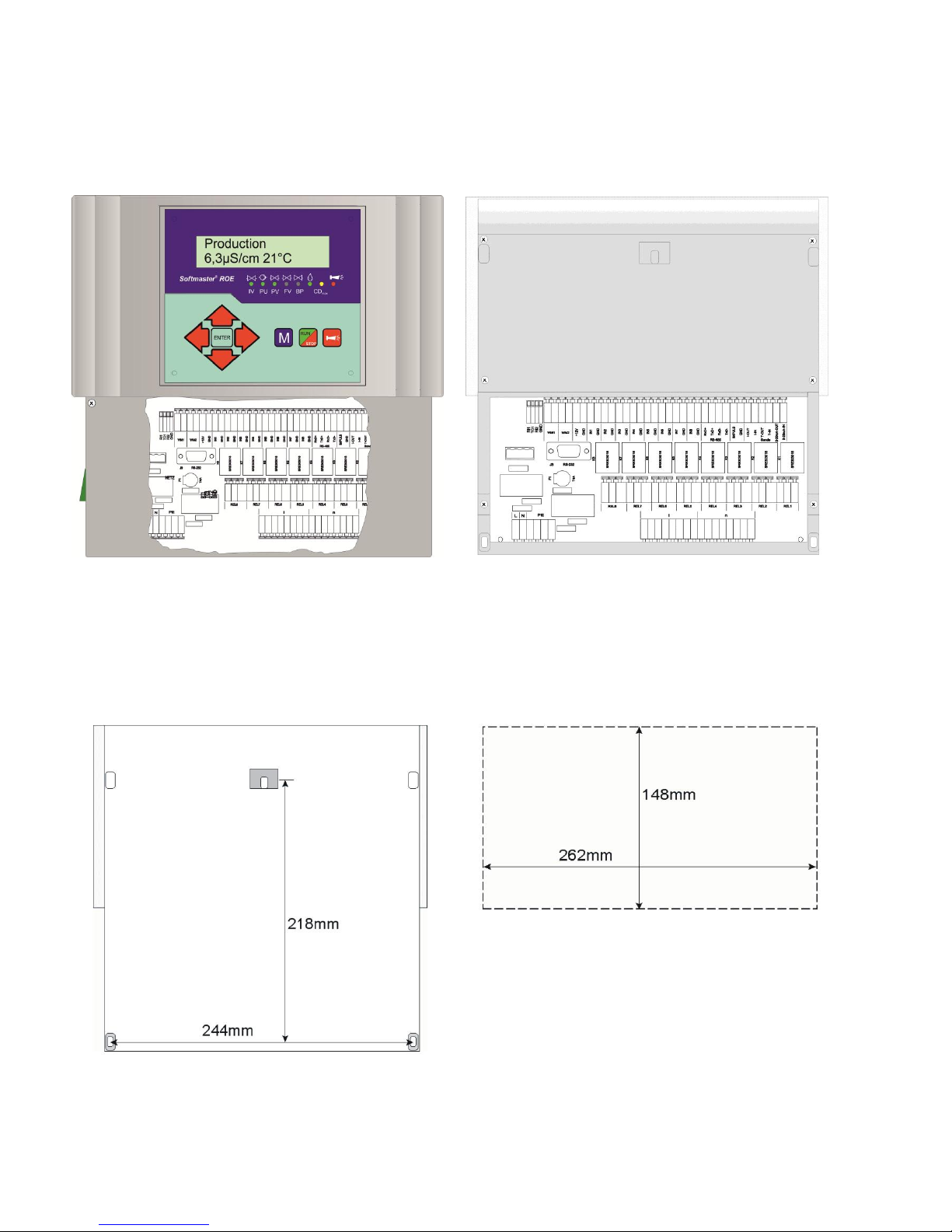
Wall-mounted variant .............. Panel-mounted variant
Terminal box .............. Terminal box
Drilling scheme for wall-mounted variant Panel cut-out for panel-mounted variant
Page 5
535
Description of display and operating features
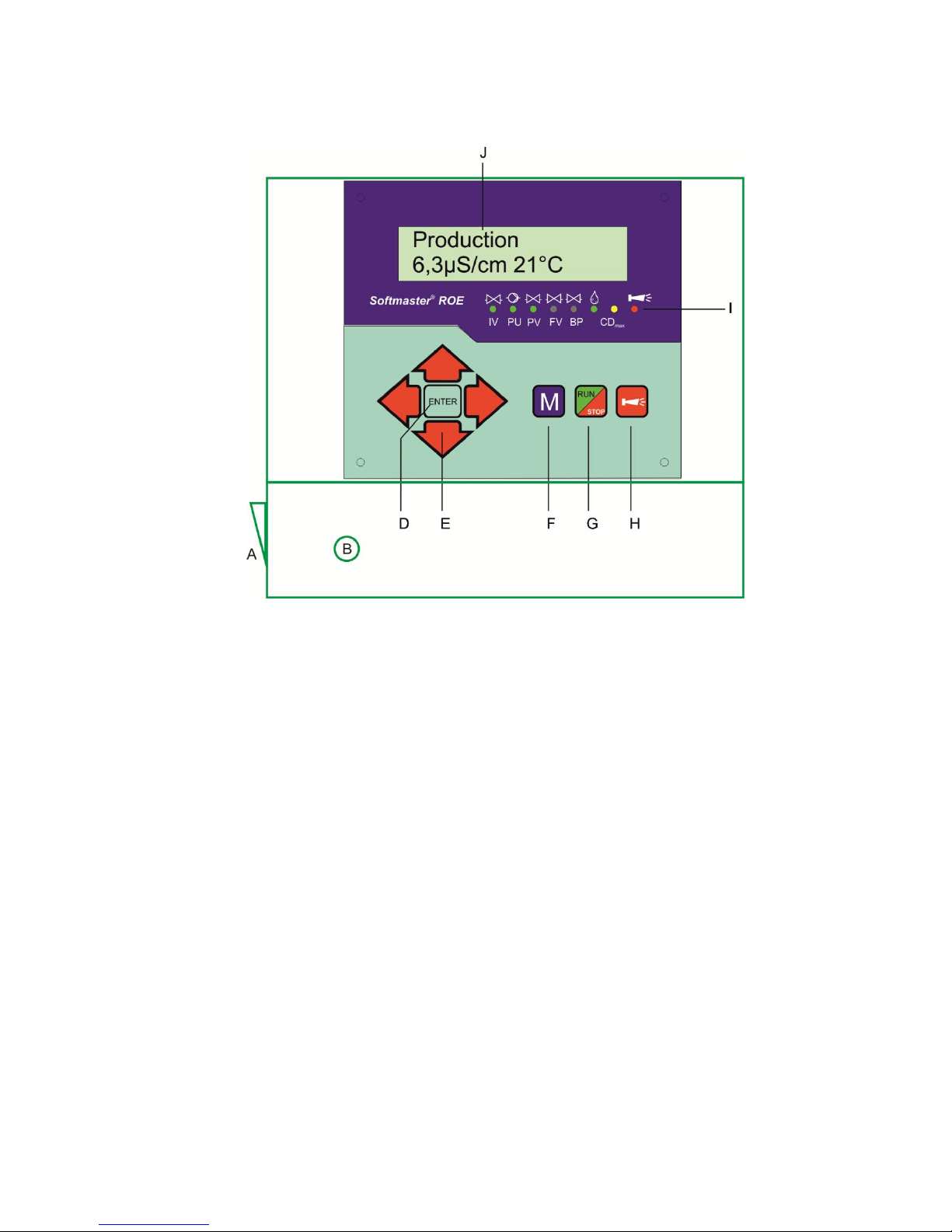
A On/Off switch
Only the wall-mounted variant is equipped with a On/Off
switch. Use this switch to switch the unit on or off.
B Safety fuse, max. T6.3A
The safety fuse protects the outputs against overload or a
short circuit. (Inside the unit)
C Thermal fuse (optional)
Thermal fuse protection for the pump motor, max. 6.3 A.
D "ENTER" key
Confirm inputs and trigger functions with the ENTER key.
E Arrow keys
Use these keys to operate the menu drive in the display
and to enter values and programming data.
F "M" key
Call the menu and return from submenu levels.
G "Run/Stop" key (AProduction/Standby@)
Manual triggering of production: Plant is put into
operation or manual triggering for STOP/ Standby: Plant
goes into the Standby position.
H "Fault OFF" key
Deletes the alarm signal at output 'AL' (Alarm); a fault
display can only be deleted if the fault has been
eliminated.
I LED functions
LED symbols always signal the status of the plant,
independent of the level (menu) being worked on.
J LC display
Two lines, each line with 16 characters, backlit.
Page 6
635
Display functions
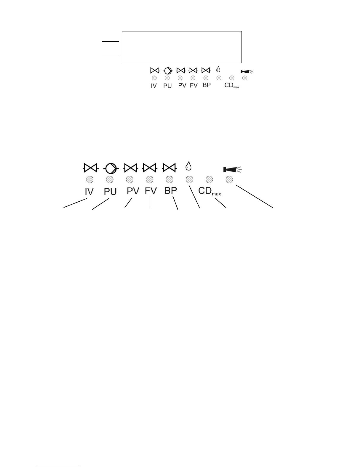
Display - top line
The top line displays plant statuses and error messages (described below).
Display - bottom line
The bottom line displays the conductivity (see technical data for measuring ranges) and water temperature (2-digit, only
with automatic temperature compensation).
LED displays
The LEDs display active plant components and occurring error messages.
IV (green)
LED lights up: Input valve is open.
PU (green)
LED lights up: Pump 1 and/or pump 2 is/are switched on.
PV (green)
LED lights up: Output/Permeate valve is open.
FV (green)
LED lights up: Flush valve is open.
BP(green)
LED lights up: By-pass valve is open.
Metering message (green)
LED lights up as long as the impulse output is activated.
Warning message AConductivity too high@ (yellow)
LED lights up: The limit value CDmax has been exceeded.
Error message AAlarm@ (red)
LED lights up: Alarm relay activated, error message not confirmed yet and error still occurring.
LED flashes: Alarm relay no longer active, error message has been confirmed but the error is still occurring.
As long as an error is still occurring, it is shown alternately with the operating display.
Production
2.4µS/cm 18°C
Display of water
temperature
(raw water or permeate)
Display of
plant statuses
Display of active plant
components
Display of
permeate conductivity
IV =
Input valve
PU =
Pump
PV =
Output/
Permeate
FV =
Flushing
valve
BP =
By-pass-
valve
Dosing-
message
Warning message
„Permeate
conductivity too
Error
message
Page 7
735
Operating displays
Plant is in operation and produces permeate with 12.3μS/cm of conductivity at
a water temperature of 21C.
Plant is on Standby with a permeate conductivity of 243 μS/cm.
Flush program is active (flush after production or interval flush),
Residual time 10 minutes.
Quality flush during production is active with a permeate conductivity of
197.3μS/cm.
The LED ACDmax@ lights up additionally.
Program the duration of the quality flush in the BASIC PROGRAM menu.
Plant has been stopped via the STOP input and is locked. It is only possible to
restart production with the ARun/Stop@ key after the stop input has been
released.
Error messages
In addition to the displayed error messages, the red LED AAlarm@ lights up or flashes.
Alternate display of all error messages and operating displays.
Each occurred error is stored in the error history.
Error message APower failure@
............................... or
Message after each switching on: @power failure@. Acknowledge the fault display via the @Alarm@ key. Check the time and,
if necessary, set the time. After this, the unit is without a real-time clock (plug-in card RTC/RS232).
After switching on or after voltage recovery, the controller starts with @STANDBY@.
Check the plant for possible negative results due to the power failure.
All stored values remain stored even during power failure. The real-time clock is battery buffered and thus keeps on
running.
Production
12.3μS/cm 21°C
Standby
243μS/cm
Flush
10m
Quality Flush
197.3μS/cm
Stop
Power failure
Power failure
set clock !
Page 8
835
Error message ACD Permeate Max@
Permeate conductivity is bigger than the set limit value ALV Permeate Max@
The maximum permeate conductivity has been exceeded for a longer period than the programmed test time (Delay Max)
during. The error message is displayed and, according to the programming, the plant has been switched off.
In addition to the error message, the yellow warning light @CDmax@ lights up.
Confirm the fault display via the @Alarm@ key.
Check the plant settings and raw water quality or check the units for possible defects.
The error display is only deleted after the fault has been eliminated
Error message ACD Permeate Min@
Permeate conductivity is smaller than the set limit value ALV Permeate Min@.
The minimum permeate conductivity has fallen below the limit value for a longer period than the programmed test time
(Delay Min) during production. The error message is displayed and, according to the programming, the plant has been
switched off.
Confirm the fault display with the AAlarm@ key.
Check the conductivity sensor and its supply lines for interruption. There might be air in the permeate line and the sensor
is not washed by water.
The error display is only deleted after the fault has been eliminated.
Error message ATemperature Max@
The water temperature is higher than the set limit value ALV Temperature@
The maximum water temperature has been exceeded for a longer period than the programmed test time (Delay) during
production.
Confirm the fault display with the AAlarm@ key.
The error display is only deleted after the fault has been eliminated.
Error message ALow water pressureA
The pressure switch in front of the pressure pump for the dry-running protection
has triggered.
The plant has been switched off after the programmed delay time (Delay LP). Restart the plant with the "RUN/STOP"
key. If water is still low, the plant is switched off again after the delay time.
When automatically controlling the re-filling of the storage tank, the plant is restarted 10 minutes after it has been
switched off via the dry-running switch.
Program the number of restart attempts after low water pressure under ASwitch on@ in menu AFunct. low water pressure@.
Confirm the fault display with the AAlarm@ key.
The error display is only deleted after the fault has been eliminated.
CD Permeate Max
64.4μS/cm
Low water pressure
16.8μS/cm 18°C
Temperature Max
16.8μS/cm 43°C
CD Permeate Min
1.2μS/cm
Page 9
935
Error message AExcess pressure@
The pressure switch behind the pressure pump for the protection of the units
against excess pressure has triggered.
The plant has been switched off after the programmed delay time (Delay HP). Restart the plant via the "RUN/STOP" key.
If renewed excess pressure occurs, the plant is switched off again after the delay time.
Confirm the fault display with the AAlarm@ key.
The error display is only deleted after the fault has been eliminated.
Error message AMotor protection@
The motor protection circuit breaker of the pressure pump has triggered.
After triggering the protective switch, the plant has been switched off immediately. Restart the plant via the "RUN/STOP"
key if the motor protection has been re-released.
Confirm the fault display with the AAlarm@ key.
The error display is only deleted after the fault has been eliminated.
Error message AConcentrate flow@
The flow controller in the concentrate line has triggered because the
concentrate quantity is too low.
The error message is displayed and, according to the programming, the plant has been switched off after the
programmed delay time (Delay CO). Restart the plant with the "RUN/STOP" key.
Confirm the fault display with the AAlarm@ key.
The error display is only deleted after the fault has been eliminated.
Error message AConductivity measuring range has been exceeded@
The measuring range of the conductivity measuring instrument has been
exceeded.
Confirm the fault display with the AAlarm@ key.
Check whether short circuiting has occurred in the sensor or its supply lines and also check the programming of the cell
constants.
Confirm the fault display with the AAlarm@ key.
The error display is only deleted after the fault has been eliminated.
Error message ATank overflow@
The storage tank is overflowing.
The tank overflow signal occurs at contact input PROG and the input is
programmed as ATank overflow@ contact.
Confirm the fault display with the AAlarm@ key.
Check the storage tank and its tank overflow line as well as the AFULL@ contact of the level controller.
The error display is only deleted after the fault has been eliminated.
Tank overflow
16.8μS/cm 18°C
Exceed range CD
OFL μS/cm 18°C
Concentrate flow
16.8μS/cm 18°C
Motor protection
16.8μS/cm 18°C
Excess pressure
16.8μS/cm 18°C
Page 10
1035
Error message AExcess quality flushing duration has been exceeded@
Even after quality flush, the permeate conductivity is still bigger than the set limit
value ALV Permeate Max@.
The error message is displayed and emergency service starts.
The yellow warning light ACDmax@ additionally lights up.
Confirm the fault display with the AAlarm@ key.
Check the settings of the plant and the raw water quality or check the units for possible defects.
The error display is only deleted after the fault has been eliminated.
Error message ATemperature low@
The water temperature is lower than 0.5C.
The water temperature during production has fallen below the minimum water temperature.
Check whether short circuiting has occurred in the sensor or the temperature sensor PT100 or in their supply lines.
Confirm the fault display with the AAlarm@ key.
The error display is only deleted after the fault has been eliminated.
Error message AEmergency program / By-pass@
The level in the storage tank is below Empty-level.
The signal occurs at contact input PROG and the input is programmed as
AEmergency program BP@ contact.
Confirm the fault display with the AAlarm@ key.
Check the plant and, if necessary, its design as well as the AEMPTYA contact of the level controller. It is possible that it is
not sufficiently supplied if the production from the storage tank is too high.
The error display is only deleted after the fault has been eliminated.
Exc.Q-flush. time
196.2μS/cm 18°C
Temperature low
16.8μS/cm 0°C
Emerg.program /BP
16.8μS/cm 18°C
Page 11
1135
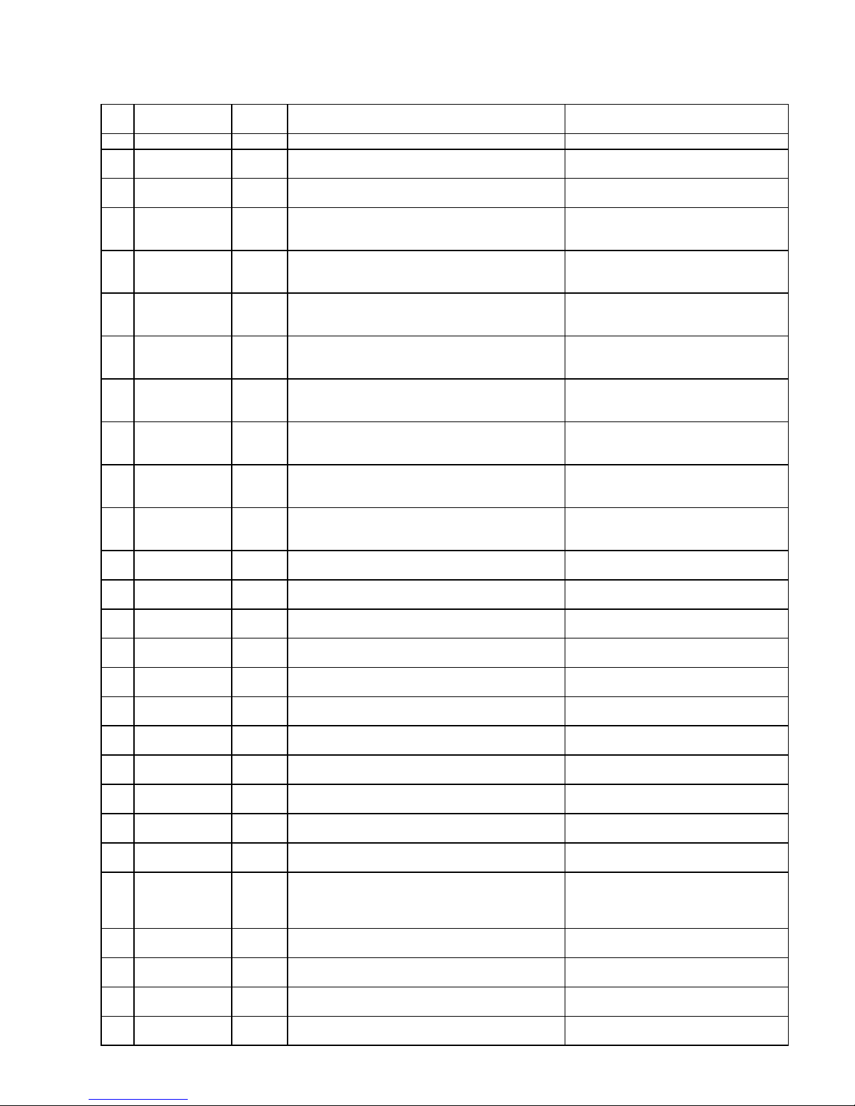
Terminal block identification
Functions (IN = input, OUT = output)
No.
Terminal
Type
Function
Note
PE
IN
4x Mains-Protective earth
N
L
IN
Mains, N = Neutral
Mains, L = Live
Mains-input
230 - 240 V AC
n
l
OUT
8x Neutral switched
8x Live switched
Mains voltage, max. 4 A
1
2
3
PU1
OUT
Pump 1 - normally open
Pump 1 - common
Pump 1 - normally closed
Mains voltage, max. 6 A
4
5
6
PU2
OUT
Pump 2 - normally open
Pump 2 - common
Pump 2 - normally closed
Mains voltage, max. 6 A
7
8
9
IV
OUT
Input valve - normally open
Input valve - common
Input valve - normally closed
Mains voltage, max. 4 A
10
11
12
PV
OUT
Output valve - normally open
Output valve - common
Output valve - normally closed
Mains voltage, max. 4 A
13
14
15
FV
OUT
Flush valve - normally open
Flush valve - common
Flush valve - normally closed
Mains voltage, max. 4 A
16
17
18
BP
OUT
By-pass valve - normally open
By-pass valve - common
By-pass valve - normally closed
Mains voltage, max. 4 A
19
20
21
PR
OUT
programmable message output ATank empty@,
ACdmax@, AStop@
(see "Programming")
Volt-free relay output
max. load 240 V AC, 4 A
22
23
24
AL
OUT
Fault message output - normally open
Fault message output - common
Fault message output - normally closed
Volt-free relay output
max. load 240 V AC, 4 A
25
26
WM1
┴
IN
Water meter input 1
common load for inputs
See water meter description!
27
28
WM2
┴
IN
Water meter input 2
common load for inputs
See water meter description!
29
30
+12V
┴
IN
12V-supply for turbine
common load for inputs
See water meter description!
31
32
HP
┴
IN
Overpressure message
common load for inputs
Only for volt-free normally open/ normally
closed contact!
33
34
LP
┴
IN
Low water message
common load for inputs
Only for volt-free normally open/ normally
closed contact!
35
36
CO
┴
IN
Concentrate monitoring
common load for inputs
Only for volt-free normally open/ normally
closed contact!
37
38
HL
┴
IN
Storage tank FULL
common load for inputs
Only for volt-free normally open/ normally
closed contact!
39
40
LL
┴
IN
Storage tank EMPTY
common load for inputs
Only for volt-free normally open/ normally
closed contact!
41
42
MP
┴
IN
external motor protection circuit breaker
common load for inputs
Only for volt-free normally open/ normally
closed contact!
43
44
STOP
┴
IN
Stop plant
common load for inputs
Only for volt-free normally open/ normally
closed contact!
45
46
PROG
┴
IN
Emergency service (By-pass), see "Programming@
common load for inputs
Only for volt-free normally open/ normally
closed contact!
47
48
49
50
RxD+
I-OUT- / TxD+
RxD-
I-OUT+ / TxD-
OUT/
IN
Current interface 0/4-20mA (standard)
Serial interface RS485 (optional)
- indirect-coupled
- RS485, not indirect-coupled
51
52
Impulse
OUT
Metering impulse (open collector)
Emitter
Max. load 50mA / 30V, see metering
output description
53
54
CD1
IN
Conductivity electrode for permeate
55
56
PT100
IN
Temperature sensor PT100
Water temperature (permeate or raw
water)
57
58
┴
IN 4-20mA
IN
common load
Signal of pressure sensor
4-20mA-input, see pressure input
description
Page 12
1235
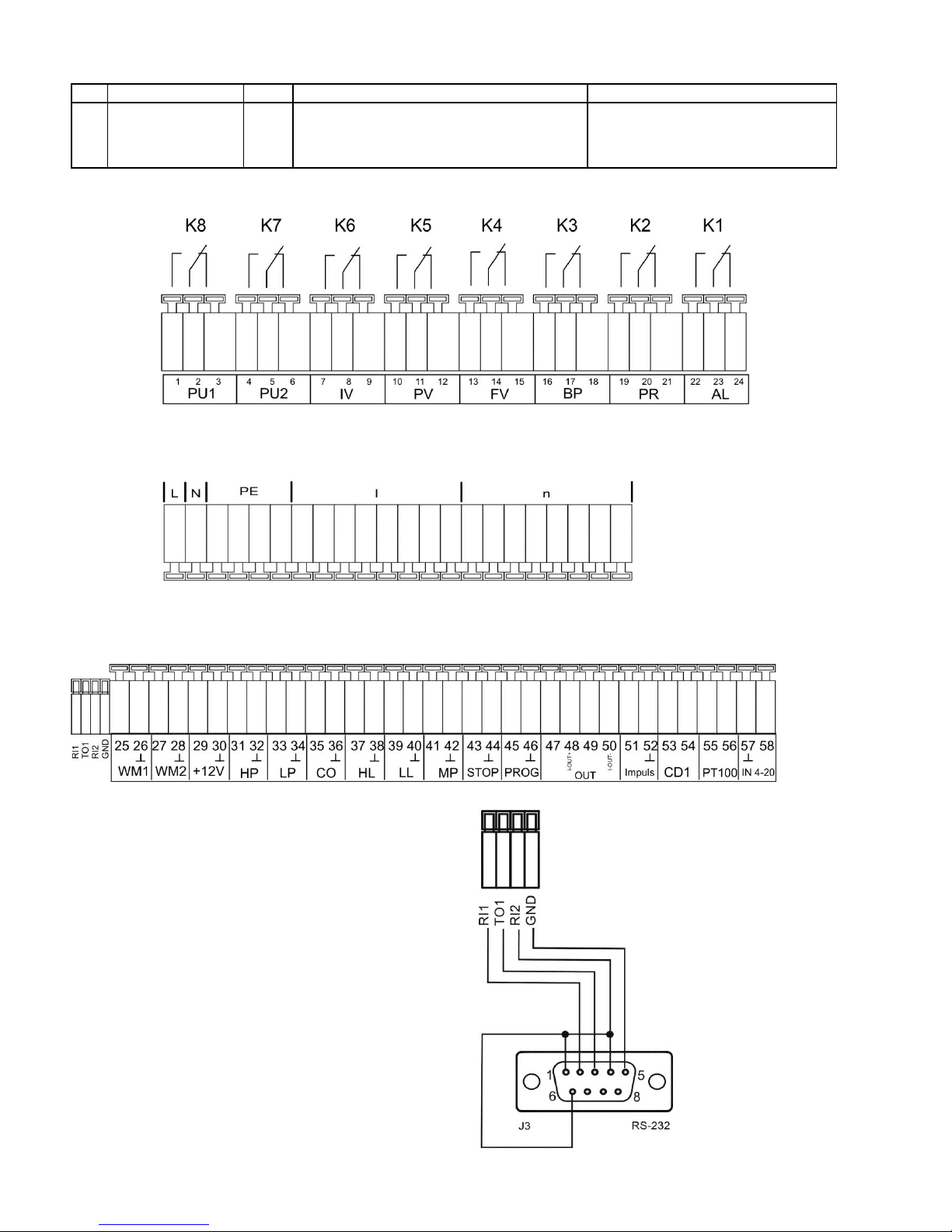
Continuation of terminal block identification
No.
Terminal
Type
Function
Note
RI1
TO1
RI2
GND
IN/
OUT
Serial interface RS232, RxD
Serial interface RS232, TxD
Serial interface RS232, DTR/DSR
Serial interface RS232, load
Parallel to D-SUB-plug RS-232 (J3)
Terminal blocks for mains supply and relay outputs (displayed relay position: Device reenergised)
Terminal block for inputs and interface
Serial interface RS232
PIN 2 - RxD
PIN 3 - TxD
PIN 4 - DSR, DTR
PIN 5 - GND, load
Please observe that the peripheral devices are
connected via a neutral modem cable!
Page 13
1335
Description of relay outputs
PU1 / PU2, pressure pumps 1 and 2
Driving motors with different power consumptions can be used for the pressure pump of the osmosis plant. Fuse
protection occurs internally via a safety fuse T6.3A. When using a three-phase motor, an appropriate power protection
contactor has to be pre-connected.
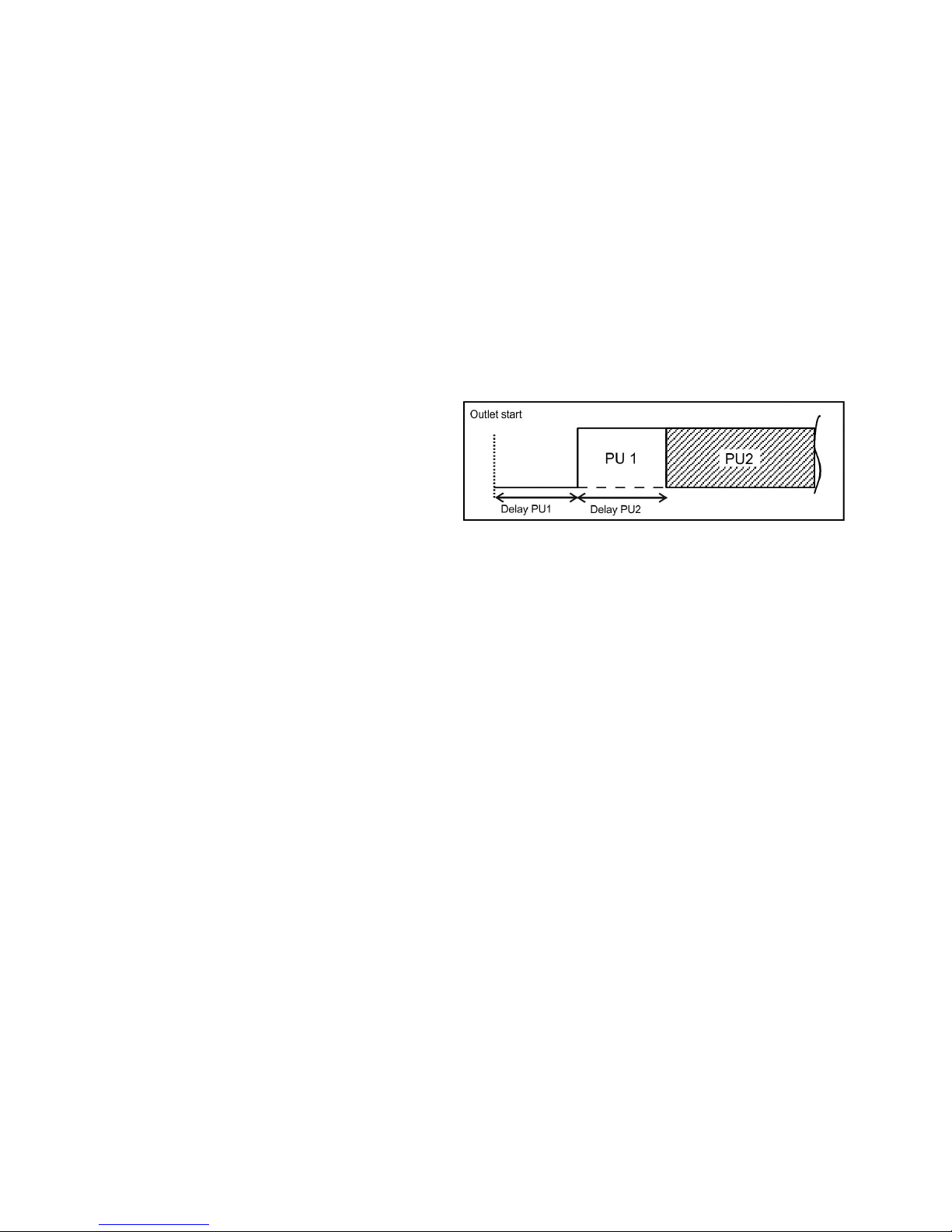
The input valve always opens when switching to production. The pressure pump starts after a programmable delay time.
Four operating modes can be selected:
- Production only with pump 1,
- Production only with pump 2,
- Serial connection = Pump 1 and pump 2 are connected in series. Output PU2 is switched with a delay after PU1 has
been switched on.
- Change-over connection: The pumps are installed in parallel and are operated alternately.
Set the operating mode and test time under menu option
"M" BASIC PROGRAM Fct.Pump
If the pump is equipped with a motor protection circuit breaker with a volt-free message contact, it is possible to connect
it to input "MP". The controller will then monitor pump faults (see description of input MP motor protection).
Cycle diagram pump delay:
IV Input valve
The input valve is open during "ProductionA, AQuality flush@ and AFlush". It should be designed in a way that it opens
under control voltage. Use the following menu option to program that the input valve is closed during flush:
"M" BASIC PROGRAM FLUSHING MODE with valve IV
FV Flush valve
The osmosis plant can be equipped with a flush valve in order to avoid unacceptable high deposits at the units. Flush can
take place after the end of the "Production" and/or in fixed intervals after the last switching to the "Standby" position.
Interval flush prevents unacceptable bacterial contamination of the units.
Flush is interrupted as soon as the controller switches to "Production", e.g. when pressing the "Production" key or if
water is requested via a level transmitter in the storage tank.
No interval flush occurs after production stop.
Program the flushing duration (0 - 99 minutes), flushing mode (with/without pump or with pump 1 + 2) and the interval
flush in the basic program.
"M" BASIC PROGRAM FLUSHING DURATION or FLUSHING MODE or INTERVAL FLUSH.
PV Output valve (Permeate valve)
This valve is open as long as the water conductivity is below the set limit value "LV Permeate Max". A flush valve which
closes under voltage can be connected instead of the output valve. The use of both valves or of a 3/2-way valve is also
possible. Use the following menu option to program whether the output valve should be closed or not during flush:
"M" BASIC PROGRAM FLUSHING MODE with valve PV
Page 14
1435
+
BP By-pass valve (emergency program)
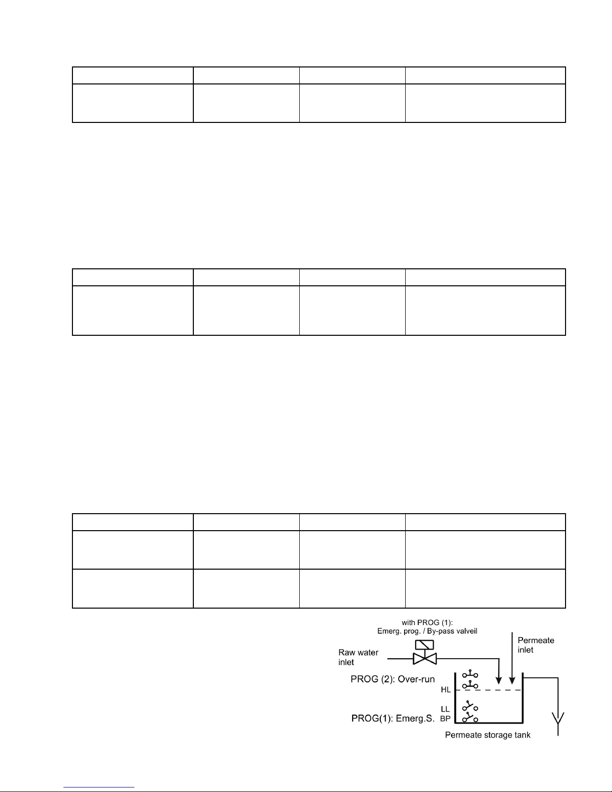
A level transmitter which is installed below the empty level of the storage tank is required for the operation of the plant
with emergency program. Connect the switch to the input "PROG". Output "BP" switches if the level "Emergency
program" is insufficient.
"M" BASIC PROGRAM Funct. PROG Em.program/BP
PR programmable function output
It is possible to program the function of this volt-free relay output as follows:
1. CDmax: Relay switches if the conductivity @CDmax.@ has been exceeded
and/or
2. Tank empty: Relay switches if the storage tank is empty
and/or
3. Production: Relay switches if the plant is in operation
and/or
4. Stop/Standby: Relay switches if the plant is in Standby or has been stopped
"M" BASIC PROGRAM Funct. OUT PR
AL Fault message output ("Alarm")
Output "AL" is a volt-free change-over relay contact. During trouble-free operation, the contact between the terminals 22
- 23 is closed and the one between terminals 23 - 24 is open. During power failure or if an error occurs, the contact
between terminals 23 - 24 is closed and the one between 22 - 23 is open.
The controller monitors several plant statuses. Output "AL" remains activated (terminals 22 - 23 closed) until the fault
ceases.
A fault is displayed with the red LED "Error message" and on the display.
The fault message signal at output "AL" is deleted by confirming the fault with the "Alarm" key.
The fault display can only be deleted if the fault has been eliminated.
The following faults activate output "AL" and are displayed if the osmosis plant has been equipped with the appropriate
sensors:
Statuses which always trigger a fault message:
Power failure
Motor protection MP
Low water pressure LP (after switch off)
Concentrate low CO
Excess pressure HP
Max. q. flushing duration exceeded
Min. conductivity exceeded
Max. conductivity exceeded
Cond. measuring range exceeded
Max. water temperature exceeded
Min. water temperature insufficient
Max. pressure exceeded
According to the programmed PROG input:
Emergency program (By-pass) active
Tank overflow
See the section entitled @Programming@ for further descriptions about error messages.
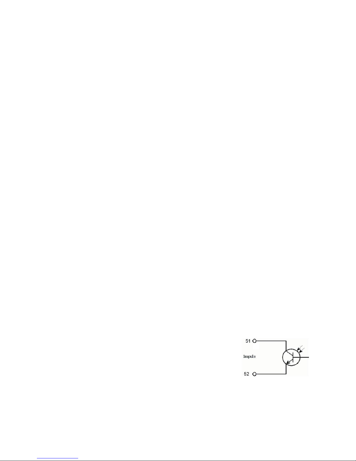
Impulse / Metering output
Use the output "Impulse" to control a dosing pump if an anti-scaling medium is to be
dosed during production or flush. For this, a water meter has to be connected to input
"WM1" or "WM2". The impulse ratio is adjustable.
Example:
An impulse length of 1 second should be given per 50 litres:
L/Imp. = 50, I.length = 1sec
"M" BASIC PROGRAM Metering
"M" BASIC PROGRAM Water meter 1
"M" BASIC PROGRAM Water meter 2
The output is an open collector transistor with a max. load capacity of 50mA / 30V.
Page 15
1535
Description of signal inputs
Note!
Connect the signal inputs "MP", "HL", "LL", "HP", "LP", "STOP", "CO" and "PROG" only to volt-free contacts!
MP Motor protection
When using pumps which are equipped with a motor protection circuit breaker with a volt-free message contact, it is
possible to connect this switch to input "MP". The controller will then monitor and, according to the programming,
evaluate pump faults.
Type of connection in plant concepts with two pumps:
Function
Test time
Type of contact
Type of contact
connection
Action
S Message contact of
an external motor
protection circuit
breaker
2 seconds
Normally closed
Serial connection
S Switch off
S Continuous alarm
S Entry in error list
Normally open
Parallel connection
Please program the input "MP" according to the operating mode of the message contact:
"M" BASIC PROGRAM Funct. Motor prot.
HL and LL High and Low level
Connections for volt-free contacts
Function
Test time
Type of contact
Action
HL
S Level transmitter input
"Full Level"
S Pressure switch input
seconds
Normally closed 2
S End production (with a connected
High level transmitter)
S Start production (with a connected
pressure switch)
LL
S Level transmitter input
"Low Level"
seconds
Normally open 2
S Start production (with a connected
Low level transmitter)
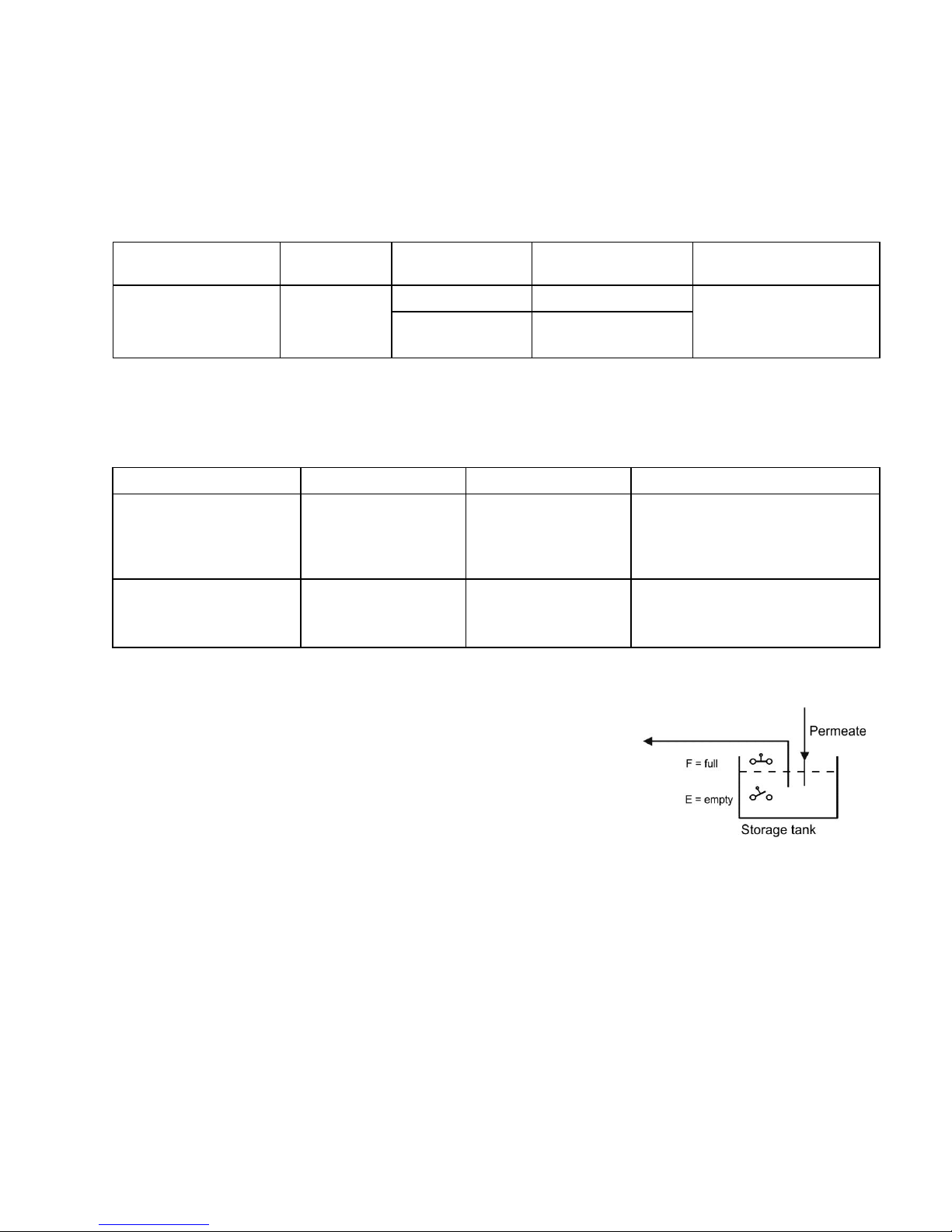
The connections "HL" and "LL" can be used for controlling the production:
a) For plants with a storage tank:
As soon as the lower level "Tank empty" (connection "LL") has been
reached, the contact transmitter closes and the plant is switched on
("Production"). It is only switched off again if the upper level "Tank
full" (connection "HL") has been reached and this contact
transmitter opens.
It is also possible to use only an upper level transmitter (float switch)
or a remote control switch (Production/Standby) instead of two level
transmitters. In this case, the connection "LL" has to be connected
via a bridge with "┴". The ARun / Stop@ key ("Production / Standby")
will then be without function.
Note!
If using automatic concentrate displacement via permeate (flush), observe that, depending on the pressure ratios, soft
water can still run into the storage tank until the end of the flushing duration. Due to this, the upper level transmitter has
to be arranged in a way that an tank overflow is avoided. For safety reasons, the tank should in any case have an tank
overflow to the drain. It is possible to install an level transmitter above the AFull levelA in order to monitor the tank
overflow.
Connect this switch to the programmable signal input "PROG". The plant automatically switches off if the "Tank overflow
level" has been reached.
Note!
When operating the osmosis plant without a level transmitter (manual operation), a bridge has to be connected across
the connection AHLA. A bridging of the connection "LL" is not allowed.
b) For plants with one pressure switch or remote control switch:
Connect a bridge to the connection "LL" and the pressure switch to the connection "HL". The pressure switch must have
a normally closed contact.
Page 16
1635
HP Excess pressure
Connection for volt-free pressure switch
Function
Type of contact
Test time
Action
Pressure monitoring in front
of or behind the unit
programmable
normally closed/
normally open
programmable
01 - 99 seconds
S Switch off of the plant
S Continuous alarm
S Entry in error list
Install a maximum pressure governor either at the raw water side or at the concentrate side in order to protect the unit. A
serial or parallel connection of two maximum pressure governors is also possible.
If the pressure governor switches, the plant is switched off after a programmable test time. The fault is displayed with the
red LED "Error message" and on the display. A continuous alarm occurs at output "Alarm" and an entry in the error list
takes place.
"M" BASIC PROGRAM Funct. Excess pressure
Press the "Production" key to restart the plant. If the pressure is still too high, the plant is once again switched off after the
test time.
Note!
When operating the osmosis plant without maximum pressure governor, the connection "HP" has to be bridged and
programmed as normally open.
LP Low water pressure
Connection for volt-free pressure switch
Function
Type of contact
Test time
Action
Pressure monitoring in front
of the pump
programmable
normally closed/
normally open
programmable
01 - 99 seconds
programmable
S Restart, up to 9 x
not programmable
S Switch off of the plant
S Continuous alarm after switch off
S Entry in error list
Install a pressure switch in front of the pump in order to protect the pressure pump. A serial or parallel connection of two
pressure switches is also possible.
If the pressure switch switches, the plant is switched off after a programmable test time. The fault is displayed with the
red LED "Error message" and on the display. A continuous alarm occurs at output "Alarm" and an entry in the error list
takes place (if the number of restarts has been reached).
"M" BASIC PROGRAM Funct. Low water
Only for controller operation with level transmitter: It is possible to program the reaction of the controller during low water.
Determine how often the plant is to be restarted.
Restart occurs after 10 minutes (fixed). If the water is still too low, the plant is once again switched off after the test time
and until the number of restarts has been reached.
Note!
When operating the osmosis plant without a pressure governor for low water identification, the connection "LP" has to be
bridged or programmed as normally open.
Page 17
1735
STOP Switch off of the plant
Connection for volt-free pressure contact
Function
Type of contact
Test time
Action
External switch off of the
plant
programmable
normally closed/
normally open
programmable
01 - 99 seconds
S switch off of the plant
During a production, it might be necessary to interrupt the production externally via a switch. In the case of
pre-connected single filter plants, the osmosis plant should not switch to AProductionA during regeneration in order to
avoid the operation of units with hard water.
The plant switches off if the input is activated (as normally closed or normally open).
The start of production and the interval flush is suppressed via the function "STOP".
"M" BASIC PROGRAM Funct. Stop
CO Concentrate monitoring
Connection for volt-free contact
Function
Type of contact
Test time
Action
Concentrate flow
monitoring
programmable
normally
closed/normally open
programmable
01 - 99 seconds
S Continuous alarm
S Entry in error list
programmable:
S Switch off of the plant
In order to protect the unit, it is possible to monitor the concentrate flow with a flow meter equipped with a limit contact
maker. The plant can be switched off after a programmable test time if the limit contact maker switches. The fault is
displayed with the red LED "Error message" and on the display. A continuous alarm or a message impulse occurs at
output "Alarm" and an entry in the error list takes place.
"M" BASIC PROGRAM Funct. Concentrate
Note!
When operating the osmosis plant without concentrate monitoring, the connection "CO" has to be bridged or
programmed as normally open.
PROG Programmable function input
Connection for volt-free contact
Function
Type of contact
Test time
Action
programmed as level
transmitter input
"Em. program/ BP"
programmable
normally
closed/normally open
none
S By-pass valve opens
S Continuous alarm
S Entry in error list
programmed as level
transmitter input
"Tank overflow"
programmable
normally
closed/normally open
none
S Production Stop, Flush stop
S Continuous alarm
S Entry in error list
"M" BASIC PROGRAM Funct. PROG
It is possible to use the input "PROG" to connect a level
transmitter (monitoring of the storage tank) for extended plant
monitoring:
Page 18
1835
Terminal block identification:
CD1 Connection for conductivity sensor
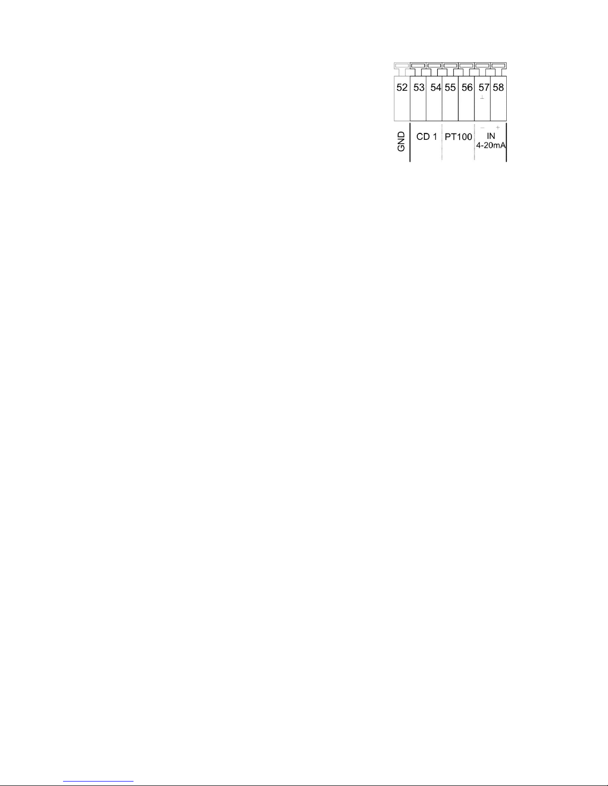
Equip the unit with a measuring amplifier for conductivity measurement.
The conductivity sensor at connection CD1 measures and monitors the permeate
conductivity.
Different measuring ranges arise due to the connection of sensors with different
cell constants: see chapter ATechnical data@.
If the measuring range is exceeded, "OFL" appears in the conductivity display and the error message AExceed
range CD@ is additionally displayed.
Program the used cell constant of the permeate monitoring under:
"M" BASIC PROGRAM Sensor Permeate
It is possible to use deviating cell constants by calibrating the sensor with a conductivity calibration solvent. Use AdryA or
zero point calibration to balance measured value distortions due to cable capacities. For this, please observe the
description about calibration.
See the function description Aconductivity monitoringA for information about the functionality of the limit values.
IN 4-20mA, Input for pressure sensor
The pump pressure before the unit/s is measured with a pressure transmitter at connection AIN 4-20mA@.
Request the current pressure in the service menu:
"M" SERVICE Pressure
Only use sensors with a 4-20mA output signal.
It is possible to program the measuring range of the used pressure transmitter:
"M" BASIC PROGRAM Funct. IN 4-20mA max. pressure
Page 19
1935
PT100 Connection for temperature sensor PT100
Function
Connection
Test time
Action
Temperature
compensation
PT100,
integrated in sensor or
external
none
Temperature compensation factor
programmable 0.01 - 9.99%/C
Temperature monitoring
PT100,
integrated in sensor or
external
programmable
1 - 99 seconds
S Continuous alarm
S Entry in error list
programmable
S Switch off of the plant
Both functions can be used simultaneously.
Please connect a temperature sensor PT100 to the input "PT100" if automatic temperature compensation (of the
conductivity) is to be used; preferably use a conductivity sensor with integrated PT100. It is also possible to use a
separate temperature sensor, but it has to be installed near the conductivity sensor.
"M" BASIC PROGRAM Temp. comp.
Water temperature monitoring
In addition to the temperature compensation, the unit can also monitor the water temperature. If a maximum value is
exceeded the plant can be switched off and an alarm can be given.
"M" BASIC PROGRAM LV temperature
OUT Interface (Terminals 47 - 50)
Function
Connection
Test time
Action
Current interface
0/4 - 20 mA
Terminals 48 / 50
Load max. 500 Ohm
-
- Conductivity Permeate CD1
serial interface
RS 485
not available at the
moment!
Terminals 47 - 50
serial bus
-
-
It is possible to change the function of the output by exchanging the plug-in module and activating the corresponding
function in the menu:
"M" BASIC PROGRAM Interface
Page 20

2035
Functioning
Switching on and power failure
After switching the unit on and after each power failure, the plant automatically returns to the Standby position. Prior to
the Standby-position another flush takes place according to the programmed flushing duration (see programming). The
plant can either be switched on manually by pressing the ARUN/STOP@ key ("Production/Standby") or, e.g.,
automatically via existing level transmitters in the storage tank.
Production / Run
Use the ARUN/STOP@ ("Production/Standby") key to switch on the pressure pump(s) of the osmosis plant. The input
valve opens and after a delay time the motor of the pressure pump starts. During production, it is possible to monitor the
raw water pressure in front of the pressure pump (dry-running protection) as well as the pressure behind the pressure
pump (overpressure protection) via pressure switches and to monitor the concentrate (concentrate flow) via a flow
controller if the osmosis plant is equipped with the appropriate sensors. Additionally, the permeate conductivity is
measured, displayed and compared with a minimum and maximum limit value.
The switching on and off can also take place automatically via level transmitters in the storage tank if the osmosis plant
is equipped with a storage tank.
It is possible to interrupt the production temporarily via an external switch (input "STOP") in order to, e.g., regenerate a
pre-connected softening plant.
Standby
Press the ARUN/STOP@ ("Production/Standby") key if water is no longer required. The pressure pump is switched off and
the display shows "Standby". If the osmosis plant is equipped with a storage tank, the switching on and off can also take
place automatically via level transmitters in the storage tank. In the case of plants with a flush valve, there is a re-rinsing
phase (flush after production) prior to the position "Standby". During this time, AFlushA is shown on the display and the
control lamp Aflush valveA (AFV@) lights up.
While switching from production to flush the pressure pump is, with opened input and flush valve, switched off for 5
seconds in order to achieve a pressure compensation of the plant.
The water pressure before and after the pressure pump, the concentrate flow as well as the conductivity limit values are
not monitored in the AStandby@ position.
Flush after production
The osmosis plant can be equipped with a flush valve (connection "FV") in order to avoid unacceptable high deposits at
the units. Flush is started after the end of the production if the storage tank is filled or by pressing the ARUN/STOP@
("Production/Standby") key.
Program the necessary flushing duration in the basic program under "Flushing duration". Please set the flushing duration
to 0 minutes if no flush is to take place after the production.
Flush is cancelled as soon as the ARUN/STOP@ ("Production/Standby") key is pressed or if water is requested via a limit
transmitter in the storage tank.
Interval flush
After the last switch off (in the Standby position), flush can occur at fixed intervals. Unacceptable bacterial contamination
of the units is avoided due to this interval flush. Enter the interval time (0 - 999 hours) and the flushing duration (1 - 99
minutes) in the basic program ("Interval flush").
Flush is cancelled as soon as the ARUN/STOP@ ("Production/Standby") key is pressed or if water is requested via a limit
transmitter in the storage tank.
With production stop, no interval flush takes place. If an interval flush is not desired, the interval time (hours) has to be
entered as @0@.
Quality flush and emergency service
During quality flush switch off at too high conductivity (LV Permeate Max: Switch off) should not be activated. During
production, it is checked whether the permeate conductivity rises above the upper limit value (LV Permeate Max).
If it is too high and quality flush (Quality flush: ON) has been programmed, quality flush is started for the programmed
duration after the end of the set test time for the upper limit value.
It is switched back to production if the conductivity falls again due to the flush. However, if the conductivity remains as
high, the emergency service starts after the quality flush. The emergency service is not shown extra on the display
(display: @Production@).
Emergency service is terminated as soon as the conductivity is below the upper limit value.
Page 21
2135
Emergency program / By-pass
The function "Emerg. Program/BP" has to be selected for the input "PROG" in the menu "Funct. PROG". In addition to
this, the contact type has to be selected. A float switch, which signals the emergency program, is connected to the input
"PROGA. It is placed underneath the empty level.
A solenoid valve is, e.g., connected to the output "BP" in order to open the by-pass line.
If more water than the plant can supply is required during the production, the level in the storage tank falls to a level
below the empty level. Emergency program starts as soon as the float switch for the emergency program responds, i.e.
the relay for output "BP" switches. This leads, e.g., to the opening of a solenoid valve in order to supply water of a
pre-connected softening plant. An additional pressure pump can also be switched on.
Emergency program ends when the empty level has been reached.
Conductivity monitoring
The integrated conductivity measuring instrument is used for the quality monitoring of the plant.
"OFL" appears on the display if the measuring range is exceeded.
Temperature compensation of the conductivity can either take place automatically or manually with a programmable
compensation factor. Sensors with PT100 temperature sensors (or external sensors) have to be used for the automatic
compensation. In the case of manual compensation (suitable with constant water temperature), enter the temperature.
See ADescription of the inputs: PT100" for further explanations.
Description of the functionality and programming of the conductivity limit values:
LV Permeate Max: Maximum conductivity value which should guarantee a sufficient water quality.
"M" BASIC PROGRAM LV Permeate Max
LV Permeate Min: Minimum conductivity value which is necessary due to the existing raw water quality. But if
conductivity does fall below this value, an error in the plant or the controller is present.
(e.g. in the case of an interruption between controller and measuring sensor = parting of a cable).
"M" BASIC PROGRAM LV Permeate Min
The functionality of the limit values is stated in the table below:
Limit value
Test time Action
LV Permeate Min
fallen below
programmable
1 - 99 seconds
S Continuous alarm
S Entry in the error list
programmable
S Switch off of the plant
LV Permeate Max
exceeded
programmable
1 - 99 minutes
S LED display ACDmax@ lights up
S Continuous alarm
S Entry in the error list
programmable
S Switch off of the plant or quality flush
Page 22
2235
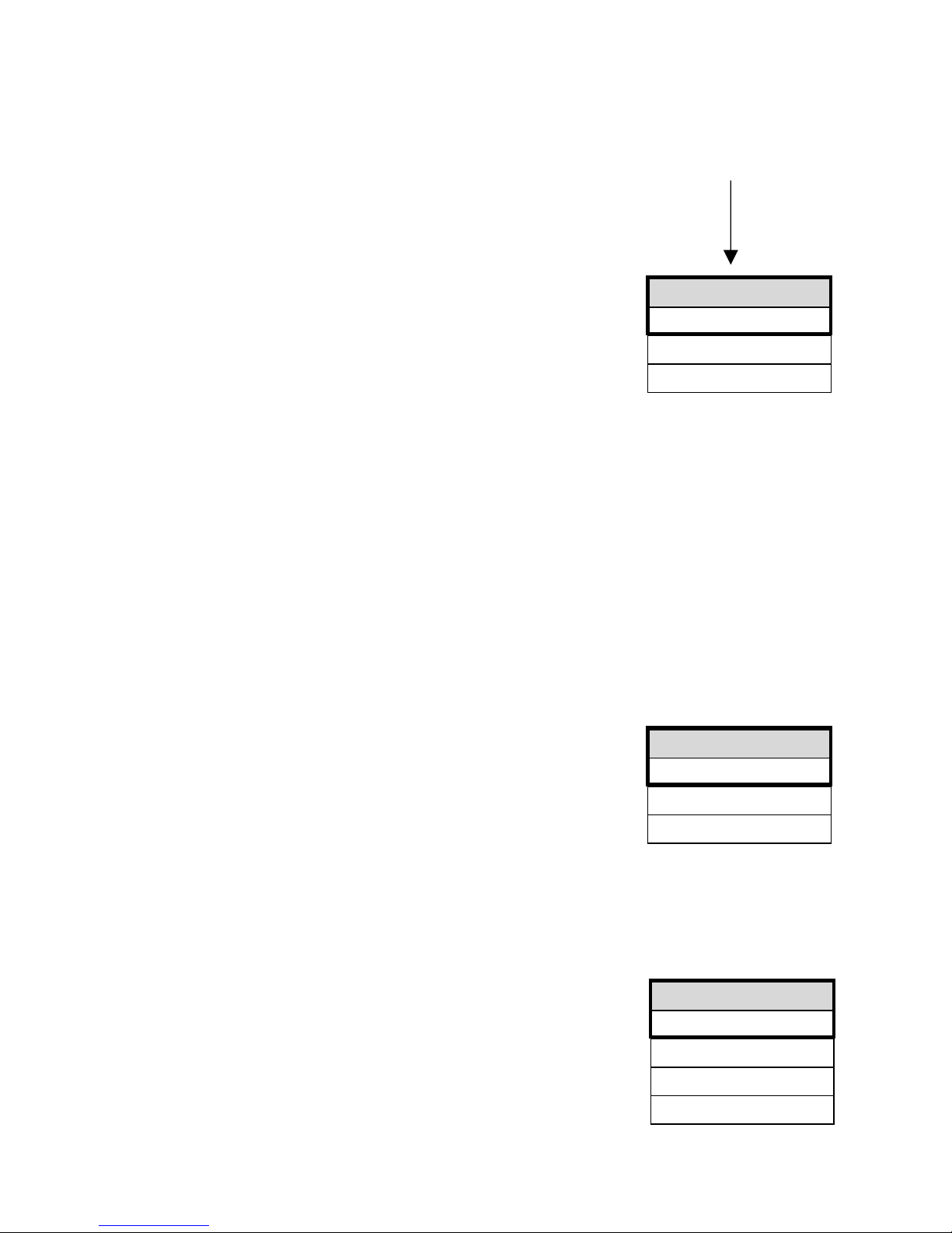
MENUE
Service
Information
Basic program
“M“
BASIC PROGRAM
Password Input
Password change
Password: 000
FLUSHING MODE
with Pump 1 -
with Pump 2
with valve IV
with valve PV
Programming
Start menu
Call the menu via the "M" key.
Menu selection
The current line position is displayed as a heading in CAPITAL LETTERS. Activate the
selected/displayed menu option with the "ENTER" key, i.e. you "jump" into a submenu.
Call the next menu point with the "DOWN" arrow key: thus you "scroll" the menu.
Input
Inputs are only possible in the program menu and in some SERVICE menu
options.
Select a programming step with the "DOWN" and "UP" arrow keys and activate the input
function via the "ENTER" key.
When entering digits, the digit/position to be changed flashes.
Change to the next or previous digit (now flashing) with the "Right" and "Left" arrow keys.
Change the value or selection with the "DOWN" and "UP" arrow keys.
Selected functions are marked with a if selection is possible. In this manual they are
marked with a * in the text.
Terminate the input function with "ENTER".
Change to the higher-order menu with the "M" key.
End menu
Return to the higher-order menu with the "M" key. After returning from the highest menu level, the unit is once again in
the display function. The controller returns to the normal operating display (automatic menu end) after 2 minutes in the
menu if a key is not pressed.
Information menu
"M" INFORMATION
Request the current settings without entering a password in the information menu.
The information menu is still displayed even if an incorrect password has been entered.
Programming
"M" BASIC PROGRAM
Enter password
The programming menu is protected by a 3-digit password (number between 000 and
999) in order to prevent unauthorised intervention in the programming.
Enter the password and confirm the input via the @ENTER@ key.
You are now in the menu PROGRAM.
Change password
Enter or change your individual password at any time. For this, enter the old password (OLD: ) and then the new one
(NEW: ).
Flushing mode
It is possible to select and combine the units which are to be activated during flush as
desired:
With pump 1 and/or with pump 2,
with output valve/permeate valve PV
and/or with input valve IV.
The flush valve FV is generally active for the duration of the flush.
Page 23
2335
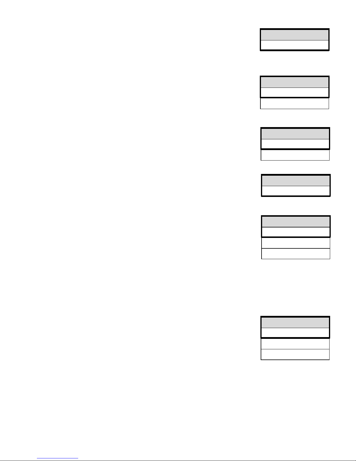
INTERVAL FLUSH
Interval 999h
Duration 99m
FLUSHING DURAT.
Duration 10m
QUALITY FLUSH
On
Durat. max 5m
PROBE CD PERM.
C = 01.00/cm
LV PERMEATE MAX
Max.: 100.0µS/cm
Delay Max 10m
Switch off
LV PERMEATE MIN
Min.: 1.5µS/cm
Delay Min 20s
Switch off
Flushing duration
Enter the desired duration for the re-rinsing (also see AFlush after production@):
The components selected under AFlushing mode@ as well as the flush valve FV are active
during flush.
Interval flush
Enter the interval for the automatic flush during standstill of the plant in hours and the
desired duration in minutes.
The components selected under AFlushing mode@ as well as the flush valve FV are active
during interval flush.
Quality flush
Depending on the permeate conductivity (quality), it is possible to start a flush during the
Production if the limit value LV Permeate Max is exceeded. The function is switched on
via @On@ and the maximum flush period can be entered.
For details see the section @Functioning@
Probe CD1 Permeate
Program the cell constant C of the used conductivity sensor:
(Possible values: 0.01 - 5.0/cm)
LV Permeate Max., Maximum limit value permeate conductivity
Max.:
Enter the maximum conductivity which should guarantee sufficient water quality.
Delay Max.
Delay time in minutes after which an alarm is triggered and/or the plant should be
switched off if the maximum limit value has been exceeded.
Switch off
Program ASwitch offA if the plant should be switched off after the end of the delay time if the maximum limit value has
been exceeded.
LV Permeate Min., Minimum limit value permeate conductivity
Min.:
Minimum conductivity value which is necessary due to the existing raw water quality. But
if conductivity does fall below this value, an error in the plant or the controller is present..
Delay Min.
Delay time in seconds after which an alarm is triggered and/or the plant should be
switched off if the value has fallen below the minimum limit value.
Switch off
Program ASwitch offA if the plant should be switched off after the end of the delay time if the value has fallen below the
minimum limit value.
Page 24
2435
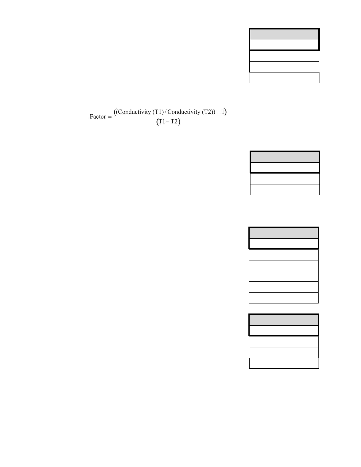
TEMP.-COMPENSAT.
automatic -
manual
Factor 2.00
Temperat. 24°C
LV TEMPERATURE
45°C
Delay 100s
Switch off
FCT.LOW W.PRESS.
norm. closed -
norm. open
Delay LP 5s
Restart 3x
FCT. PUMP
Alternate -
Serial -
only Pump 1
only Pump 2
Delay PU1 10s
Delay PU2 10s
Temperature compensation
Automatic/manual
Please connect a temperature sensor PT100 to the connection APT100" and program
automatic compensation if the temperature compensation of the conductivity should occur
automatically.
Factor (temperature coefficient in %/C)
Enter the temperature compensation factor of the medium to be measured. The value for
natural waters is approx. 2%/C. Use reference measurements to determine the
temperature coefficient for ultra pure water and with very small conductivities:
First, program the factor to 1.0 and measure the conductivity and the temperature of the medium at a temperature T1.
Then measure the same medium at a temperature T2. Use the following formula to calculate the factor.
Temperature
Please enter the existing water temperature for the manual compensation.
LV Temperature, Maximum limit value water temperature
Enter the maximum temperature for monitoring excess temperature:
Delay
Delay time in seconds after which an alarm is triggered and/or the plant should be
switched off if the maximum temperature has been exceeded.
Switch off
Program ASwitch offA if the plant should be switched off after the end of the delay time if the maximum temperature has
been exceeded.
Function Pump
Program the operating mode of the pressure pump/s of the osmosis plant:
Alternate: The pumps are installed in parallel and are operated alternately.
Serial: Pump 1 and pump 2 are connected in series. Output PU2 is switched with delay
after PU1 has been switched on.
Select the output to which the pump is connected if the plant is operated with only one
pump:
only pump 1: Output PU1 is switched
only pump 2: Output PU2 is switched
It is possible to enter the delay times for both pumps separately.
Function Low water pressure, Input low water pressure monitoring LP
Program the desired effect of the connected contact for low pressure monitoring, normally
closed or normally open.
Delay LP
Delay time in seconds after which an alarm is triggered and/or the plant should be
switched off if the water/pressure is low.
Restart
Program how often the plant is to be switched on again after the switch off caused by low water pressure.
The plant can be re-started up to 9 times until the final switch off.
Page 25
2535
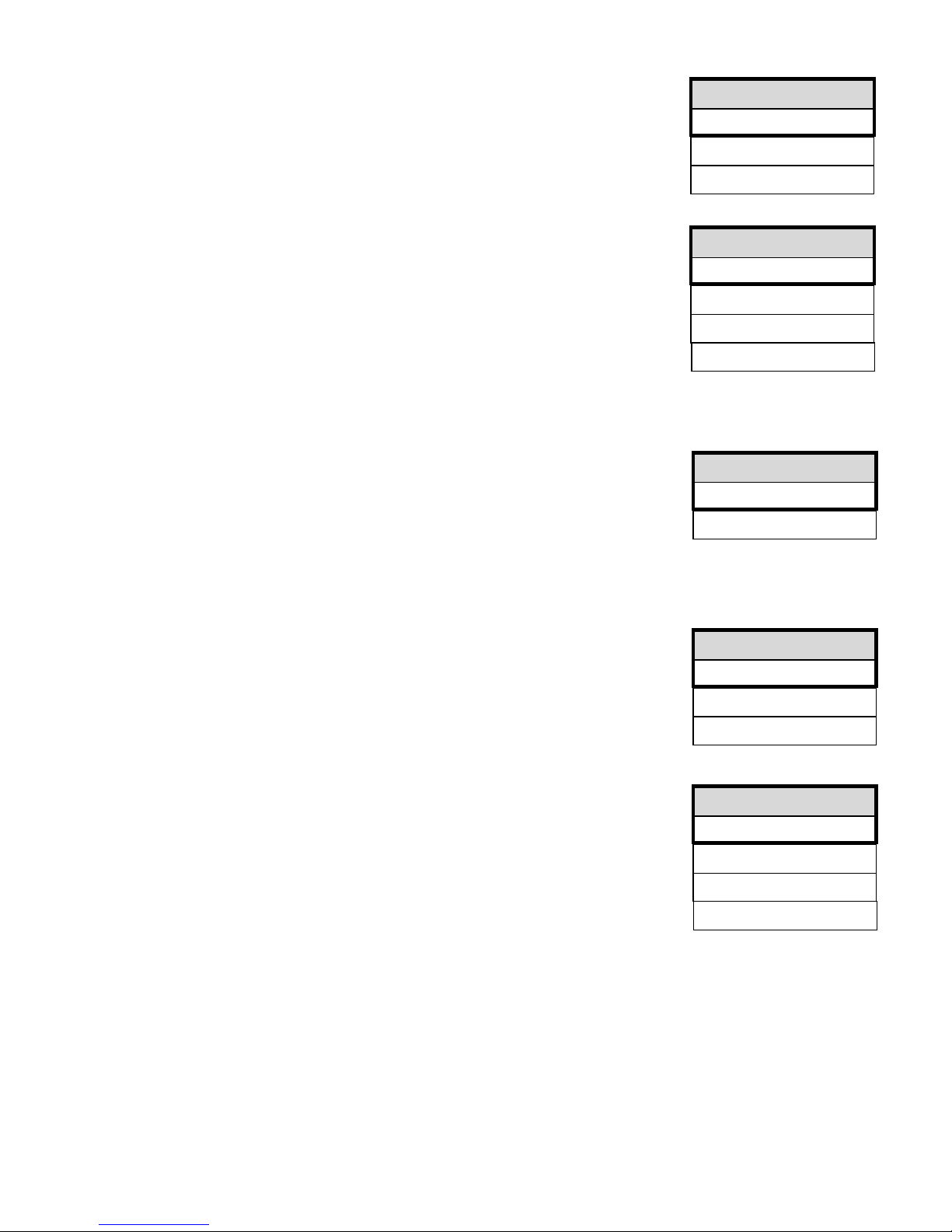
FCT.EXCESS PRESS
norm. closed -
norm. open
Delay HP 1s
FCT.MOTOR PROT.
norm. closed -
norm. open
FCT.CONCENTRATE
norm. closed -
norm. open
Delay CO 5s
Switch off
FCT. STOP
norm. closed
norm. open
Delay Stop 1s
FCT. PROG.
norm. closed -
norm. open
Em.Progam/BP -
Overflow
Function Excess pressure, Input excess pressure monitoring HP
Program the desired effect of the connected contact for monitoring the pressure pump,
normally closed or normally open.
Delay HP
Delay time in seconds after which an alarm is triggered and/or the plant should be
switched off if the pressure is too high.
Function Concentrate, Input concentrate flow monitoring CO
Program the desired effect of the connected contact for concentrate flow monitoring,
normally closed or normally open.
Delay CO
Delay time in seconds after which an alarm is triggered and/or the plant should
eventually be switched off.
Switch off
Program ASwitch offA if the plant should be switched off after the end of the delay time if the concentrate flow is too low.
Function Motor protection, Input motor protection monitoring MP
Program the desired effect of the connected contact for monitoring the driving motor of
the pressure pump/s, normally closed or normally open.
The delay time of 2 seconds after which an alarm is triggered and the pump/s
is/are switched off is predetermined and cannot be changed.
Function Stop, Stop input
Program the desired effect of the connected contact for the switch off of the plant,
normally closed or normally open.
Delay Stop
Delay time in seconds after which the plant should be switched off.
Function PROG, programmable function input
Program the desired effect of the connected contact through which the following
programmed function should be triggered, normally closed or normally open.
Emergency program/BP
The by-pass valve BP is opened. Due to this, the storage tank or a subsequent plant can
be supplied with water in the case of possible external faults.
Tank overflow
The contact input is used for the tank overflow monitoring of the storage tank. If the storage tank is overflowing, the plant
is switched off and an alarm ATank overflowA is triggered.
Page 26
2635
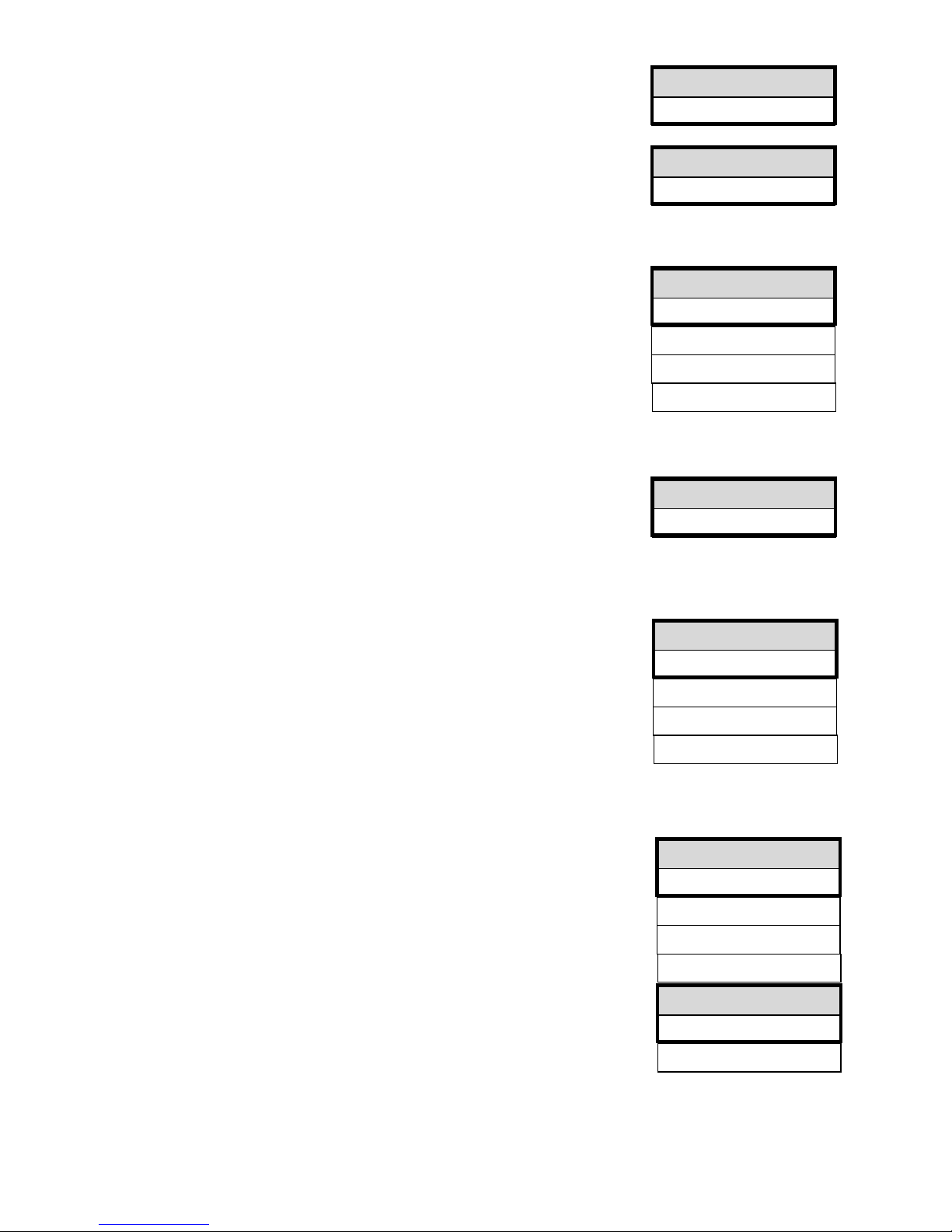
WATER METER 1
L/Imp. 1.000
WATER METER 2
L/Imp. 1.000
METERING
active WM1
active WM2 -
L/Imp. 10.000
I.length 0.5s
FCT. IN 4-20MA
Max.press. 25bar
FCT. OUT PR
CD Max
Tank empty -
Production -
Stop/Standby -
INTERFACE
RS232
RS485 -
0-20mA
4-20mA -
BAUD RATE
9600 -
19200
Water meter
The controller has two independently operating water meter inputs.
Water meter 1 can, e.g., be used to record the raw water quantity. Water meter 2 can be
used to record the permeate quantity.
Set the impulse numbers for the contact water meters or turbines in the menu:
Request the recorded quantities in the SERVICE menu, e.g.:
"M" SERVICE WATER METER 1 Quantity: 9143 l
"M" SERVICE WATER METER 2 Quantity: 4360 l
The memories of the water meters are also deleted in the SERVICE menu.
Metering
Use the output "Impulse" for the control of a dosing pump if metering is to take place
during operation. Program the water meter to be used for metering, the volume for which
an impulse is given as well as the impulse length. Please note that it is not possible to
enter an impulse interval in litres which is smaller than the basic number of the
water meter.
Alternatively, it is also possible to use the impulse output to duplicate the contact of the
water meter signal. We recommend this if you, e.g., wish to control a hardness
measuring instrument (e.g. Testomat 2000) quantity-dependently. For this, please
observe the instructions of the connected hardness measurement instrument.
Funct. IN 0/4-20mA input
Program the measuring range of the sensor if the osmosis plant is equipped with a
pressure measuring transducer for the measurement of the pump pressure:
Request the current pressure in the SERVICE menu, e.g.:
"M" SERVICE Pressure 14.3bar
Function OUT PR output
Program the function of this volt-free relay output PR:
CDmax: Relay switches if the conductivity ACDmax.@ has been exceeded
or
Tank empty: Relay switches if the storage tank is empty
or
Production: Relay switches if the plant is in operation
or
Stop/Standby: Relay switches if the plant is in standby or has been stopped.
Interface
Program the type of the built-in serial interface according to the used plug-in card. The
RS232 is a standard interface for firmware updates via PC or for connecting a protocol
printer.
The interface card RS232/RTC/0-20mA is equipped with a current transformer which can
be used for the output of the conductivity. Program the desired/necessary output signal.
Baud rate
Select the speed rate of the serial interface.
Page 27
2735
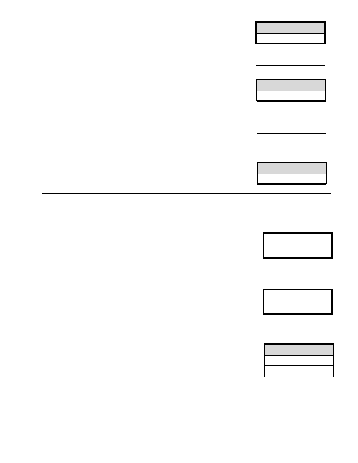
LANGUAGE
German -
English
French -
Italian -
Dutch -
Polish -
RELEASE
none
read only -
active -
SERIAL-NO.
123456
ERROR HISTORY
display
clear
Release
With the built-in serial interface, it is possible to either program the controller or to
request controller data via a PC/laptop and to carry out remote maintenance via an
analogue, digital or wireless modem (the @Softmaster ROE 2@ program is necessary):
Release mode: none = Data transfer locked
read-only = Only reading of data is allowed
active = Reading/writing of data and
programming allowed
Language
Selection of the desired display language:
At present, these five Astandard@ languages are available. Other languages are
available if desired by customers.
Serial number
With this function it is possible to display the serial number of the unit.
ASERVICE@ menu
Request and change current settings and statuses of the unit in the service menu.
Manual flush
Start a flush of the plant via this manual function. After the start a return to the operating
display occurs. The maximum flushing duration is limited to 99 minutes.
End the flush with the ARun/Stop@ key.
Automatic flush
Start a flush of the plant with the programmed flushing duration (also see "M" BASIC
PROGRAM Flushing duration) via this manual function. After the start a
return to the production display occurs.
It is possible to end the flush at any time with the ARun/Stop@ key.
Error history
Open the error history via Adisplay@. The error history is a list of the errors which have
occurred during current operation.
An occurred error is recorded with error number, time and date,
e.g.: Low w. press. 6
16:56 16.09.03
A maximum of 20 errors are stored in a circular buffer, i.e. the oldest error is overwritten by the next error if the buffer is
full.
The buffer of the error history is deleted via Adelete@ and recording restarted.
The list is not deleted after a power failure.
Flush
99m
Flush
1m
Page 28
2835
Calibration of the conductivity sensor CD
Calibration should only take place with calibration solvents in accordance with DIN EN 27888 !
Inappropriate calibration leads to undefined display values !
Dry and zero point calibration
With the calibration method CAL. CD ZERO, it is possible to compensate measuring errors (offset) which occur due to
very long supply lines to the measuring sensor.
The sensor is calibrated AdryA, i.e. it is not dipped into the measuring medium:
a) Either with a built-in sensor, before the tube system is filled
or
b) with a not yet built-in sensor, but already equipped with the correct cable length.
Call the following menu option to start calibration
"M" SERVICE Cal. CD Zero and start by pressing AENTER@.
The unit now corrects the measuring error caused by the cable length via subtraction. The process ends automatically.
Desired value calibration
With the calibration method CAL. CD desired value, it is possible to correct measuring errors caused by a soiled
sensor.
It is recommended to also calibrate with this method if there are high accuracy demands in a small measuring range.
This calibration method also enables measurements with a sensor whose cell constant is not exactly known.
Procedure:
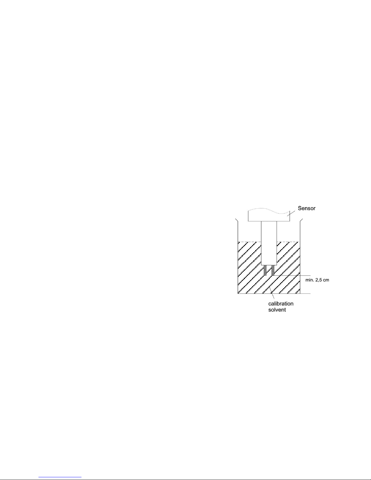
Carry out the calibration with an appropriate KCI standard calibration solvent. For
this, dip the measuring sensor into the calibration solvent. Please observe that the
sensors are free moving in the vessel.
– With automatic temperature compensation: First, enter a temperature
coefficient of 1.90%/C in the BASIC PROGRAM menu ATemp.-comp.@ and
the value of the standard calibration solvent at 25C under desired value.
After dipping the sensor into the calibration solvent, wait approx. 2 minutes
before starting the calibration until the sensor has the same temperature as
the solvent.
– With manual temperature compensation: If you wish to calibrate a sensor
without a temperature transmitter, you have to enter "manual
temp.-compensation" in the basic program and the temperature of the
calibration solvent under "Temperature". The temperature of 25C for the
calibration solvent is also valid here.
1. Call the menu ACalibrate CD@
"M" SERVICE Cal. CD Desired value
2. Enter the desired value of the conductivity and save the value by pressing AENTER@.
3. Call the following menu option to start the calibration
"M" SERVICE Cal. CD Start and start by pressing AENTER@.
The unit now corrects the measuring error by forming a correction factor. Calibration is ended automatically.
Note!
Inappropriate calibration can lead to the display of undefined values. Incorrect calibrations can only be
corrected via a new calibration or via a ACAL. CD RESET@.
Note on calibrating:
Page 29
2935
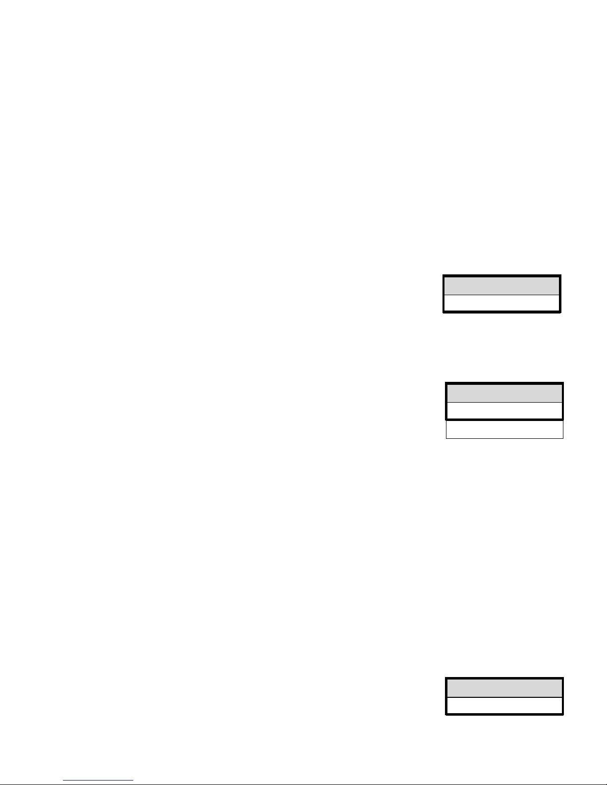
PRESSURE
5.6bar
TIME DATE
10:23 21.07.03
automatic -
SOFTWARE
91Mxxx DD.MM.YY
Operating hours
The unit records the operating hours of the pressure pump(s) and thus the load of the units. Request the current
operating time in the service menu:
"M" SERVICE Operating hours
Reset the operating hour meter:
After exchanging the pump(s) or the module, it is possible to reset the current operating time to 0 hours:
"M" SERVICE Operating hours Reset
Water meter
Both water meters are equivalent and can be used freely.
Water meter 1
Water meter 1 records, e.g., the supplied raw water quantity in litres for quantity-dependent metering.
Reset (ENTER): Leads to a reset of the currently saved total quantity.
Water meter 2
Water meter 2 records, e.g., the permeate quantity in litres counted since the last reset.
Reset (ENTER): Leads to a reset of the currently saved total quantity.
Pressure
Request the current pressure in the service menu:
Measuring input IN 4-20mA for the connection of a pressure transmitter with a 4-20mA
output is used for the pressure monitoring of the pump or the unit. Please program the
measuring range of the used pressure transmitter in the BASIC PROGRAM menu:
"M" BASIC PROGRAM Funct. IN 4-20mA max. Pressure
Time/Date
Please observe that in the case of units without a clock module the time only runs if the
unit is switched on. Correct, if necessary, the time and date after a longer period of power
failure or if the plant has been switched off.
Display: "M" SERVICE Time Date
The display shows the date and time of the controller.
Set: Press the "ENTER" key under menu "M" SERVICE Time Date.
Set the time and date by selecting the desired function with the arrow keys and trigger it by pressing AENTER@. Press the
"ENTER" key again to save the setting and to return to the display function.
Set a check mark for the automatic change-over from summertime to wintertime.
Diagnosis
The diagnosis menu displays the current statuses of the in- and outputs. For checking purposes (e.g. during
commissioning), the output statuses can be manually manipulated with the @DOWN@ and AUP@ keys. Please make sure
that downstream plant parts cannot be damaged.
Active statuses (switched relay, switched input) are represented with Aon@, inactive statuses with Aoff@, e.g.:
OUTPUT IV or INPUT MP
off on
The analogue input displays the existing value, e.g.:
INPUT MA
16.8mA
Software status
Request the current software status here:
Page 30
3035
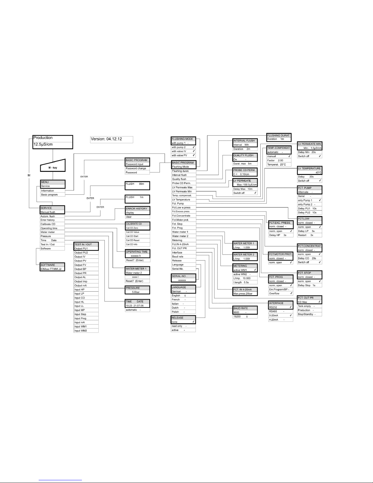
Menu structure
In order to call the factory>s basic setting, switch the unit on while pressing the ADOWN@ key. Your individual programming will be lost!
Page 31
3135
Technical appendix
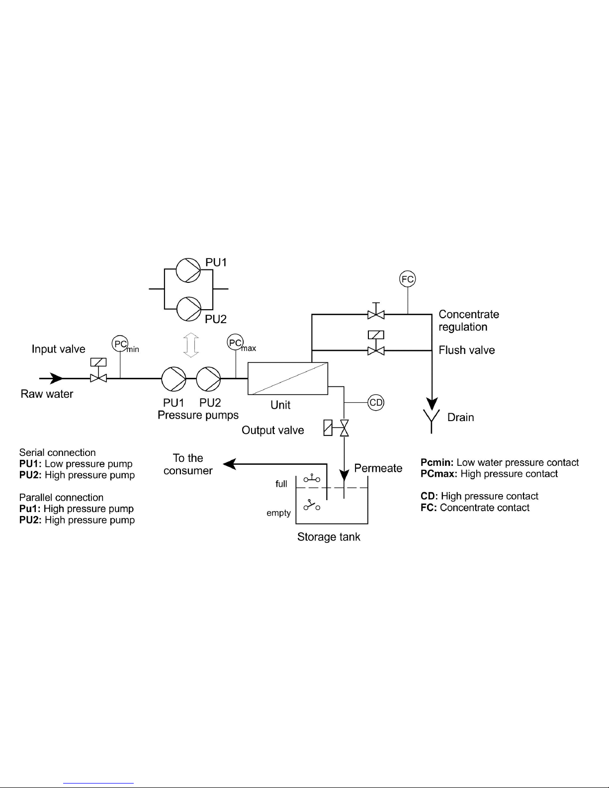
Example for an osmosis plant layout
Page 32
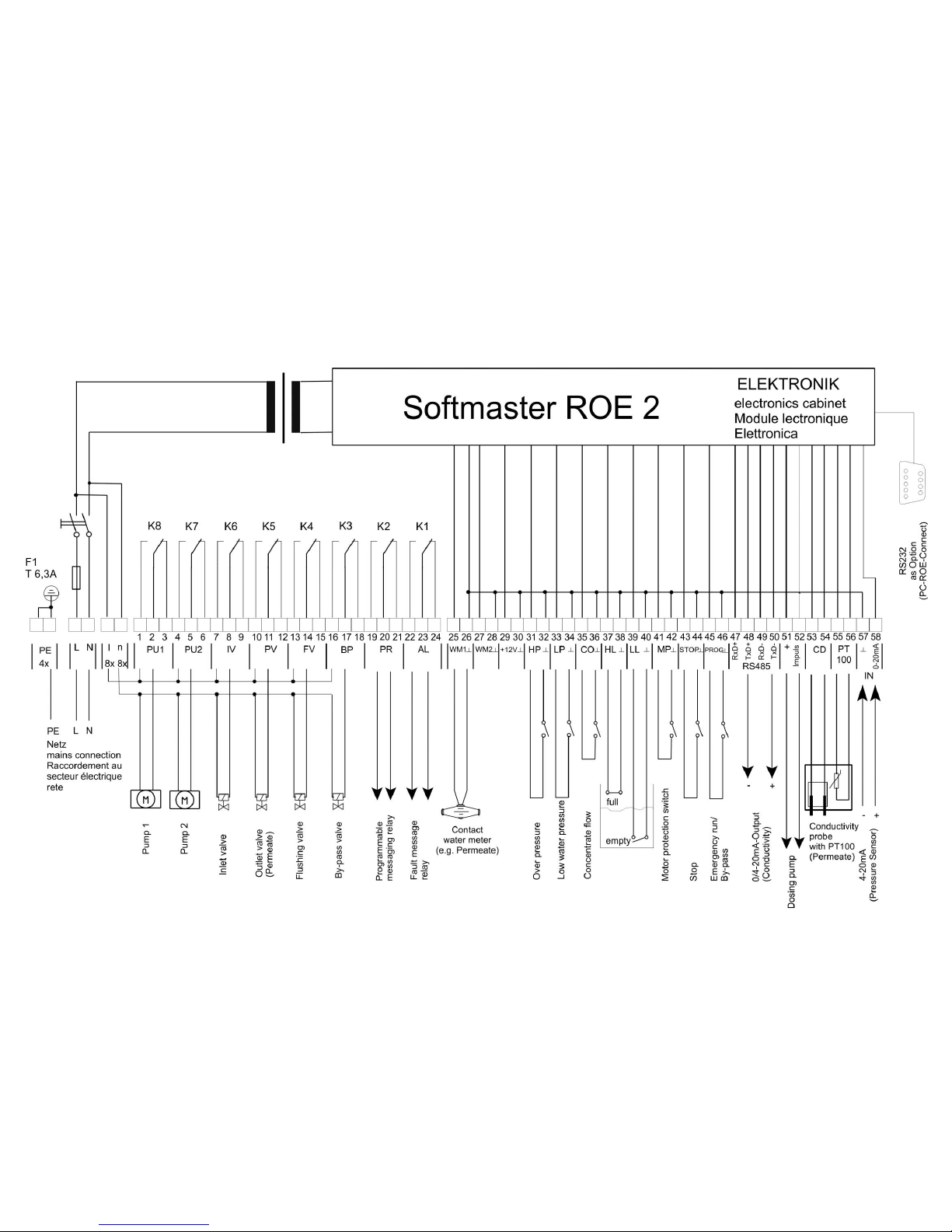
3235
Connection example (displayed relay position: Device deenergized)
Page 33

3335
Connection example for 24 V (displayed relay position: Device deenergized)
Page 34

3435
Conformity Declaration
Page 35
3535
Technical Data
Power supply: 230 - 240 V or 24 V or 115V+/-10% / 50 -60 Hz,
Safety fuse T6.3A
Power consumption without external load: max. 9 VA
Degree of protection: IP65
Protection class: I
Conformity: EN 61000-6-2, EN 61000-6-4, EN 61010-1
Ambient temperature: 0 - 45C
Measuring ranges:
Measuring range
Cell
constant
Sensor name, e.g.
0,1 – 99,9 μS/cm
0.01 cm-1
SOE0, STE0 PT100
1 – 999,9 μS/cm
0.1 cm-1
SO1, ST1 PT100, SOE1
5 – 4999 μS/cm
0.5 cm-1
SO5, SOE5, ST5 PT100
10 – 9999 μS/cm
1.0 cm-1 SD10, SO10
50 – 49999 µS/cm
5.0 cm-1
STE50 PT100
Accessories for calibration:
Conductivity solvent 1413 μS/cm 230 ml Art. No.: 425404
Housing dimensions
surface/panel-mounted ROE 2: W x H x D = approx. 270 x 295 x 130 mm
Housing made of ABS,
Panel cut-out 262mm x 146mm, +1mm,
Mounting depth approx. 90mm,
Front frame dimensions 270mm x 155mm
Weight: approx. 2.6 kg
We reserve the right to make technical changes without notice in the interest of constantly improving our products!
.............. SOFTMASTER_ROE2_GB_180424.DOCX
Gebrüder Heyl
Analysentechnik GmbH & Co. KG
Orleansstraße 75b
D 31135 Hildesheim
www.heyl.de
Scan the code and
visit us on our website!
 Loading...