

Page 1
A n e s t h e s i a S y s t e m
Operator’s Manual
Rev. 0.2 Draft – 12/09
I
NN OV AT IO N IN DES IG N AN D TEC HN OL OG Y
Page 2

Page 3

H E Y E R P a s i t h e c
Contents
1 Statement.......................................................................................................................................................................... 5
1.1 Manufacturer Responsibility...................................................................................................................................... 5
1.2 Security, Reliability and Operating Conditions........................................................................................................... 5
1.3 Return ...................................................................................................................................................................... 6
1.4 Details of the Manufacturer....................................................................................................................................... 6
2 Introduction........................................................................................................................................................................ 7
2.1 Intended Use............................................................................................................................................................ 7
2.1.1 Range of Use.................................................................................................................................................. 7
2.1.2 Contraindication .............................................................................................................................................. 7
2.2 Symbols....................................................................................................................................................................7
2.3 Definition, Abbreviation........................................................................................................................................... 10
3 System Components.........................................................................................................................................................11
3.1 Anesthetic System...................................................................................................................................................11
3.2 Breathing System ................................................................................................................................................... 17
3.2.1 Bellows Assembly Ports................................................................................................................................. 18
3.2.2 Ventilating Circulation.................................................................................................................................... 19
3.3 Vaporizer................................................................................................................................................................ 19
3.4 Anesthetic Ventilator............................................................................................................................................... 19
3.4.1 Front Panel.................................................................................................................................................... 20
3.4.2 Keys.............................................................................................................................................................. 20
3.4.3 Indicator ........................................................................................................................................................ 21
3.4.4 Navigator Knob.............................................................................................................................................. 21
3.4.5 Screen Layout............................................................................................................................................... 21
3.4.6 Rear Panel.................................................................................................................................................... 24
3.5 Menu ...................................................................................................................................................................... 25
3.5.1 Operating Guide............................................................................................................................................ 25
3.5.2 Menu Diagram............................................................................................................................................... 28
4 Operating Guide .............................................................................................................................................................. 34
4.1 Startup.................................................................................................................................................................... 34
4.1.1 System Self Test............................................................................................................................................ 34
4.1.2 Manual Leak Test .......................................................................................................................................... 36
4.1.3 Safety Valve Test........................................................................................................................................... 37
4.1.4 Automatic Leak Test...................................................................................................................................... 38
4.1.5 Compliance Test............................................................................................................................................ 39
4.1.6 Ventilation Mode Setup.................................................................................................................................. 41
4.1.7 Breathing Parameters Setup.......................................................................................................................... 41
4.2 Start Mechanical Ventilation.................................................................................................................................... 41
4.2.1 Stop Mechanical Ventilation........................................................................................................................... 41
4.3 Start Manual Ventilation.......................................................................................................................................... 42
4.3.1 Stop Manual Ventilation................................................................................................................................. 42
4.4 Shutdown ............................................................................................................................................................... 42
4.5 Waveforms ............................................................................................................................................................. 42
5 Pre-use Check List........................................................................................................................................................... 45
5.1 Pre-use Check List Procedure................................................................................................................................ 45
5.1.1 Check System............................................................................................................................................... 45
5.1.2 Main Failure Alarm Test................................................................................................................................. 46
5.2 Test Gas Supply Pipeline........................................................................................................................................ 46
5.3 Monitoring Flow Control.......................................................................................................................................... 46
5.3.1 Monitoring without Oxygen............................................................................................................................ 46
5.3.2 Monitoring with Oxygen................................................................................................................................. 48
5.4 Installing and Testing Vaporizer............................................................................................................................... 49
5.4.1 Installation..................................................................................................................................................... 49
5.4.2 Testing Vaporizer........................................................................................................................................... 49
5.5 Alarm Test.............................................................................................................................................................. 50
5.6 Breathing System Test............................................................................................................................................ 51
5.6.1 Check O2+ Button.......................................................................................................................................... 51
5.7 Ventilator Test......................................................................................................................................................... 51
6 Installation and Connection.............................................................................................................................................. 53
6.1 Install the Absorber Canister................................................................................................................................... 54
6.1.1 When to Replace Absorbent.......................................................................................................................... 54
6.1.2 Disassembling Absorber................................................................................................................................ 55
6.1.3 Filling Absorbent............................................................................................................................................ 55
6.2 Connecting Tubes and Lines................................................................................................................................... 55
6.2.1 Connect CO2 Monitor..................................................................................................................................... 56
6.2.2 Connect Anesthetic Agent Monitor................................................................................................................. 57
6.3 Connecting Gas and Electricity............................................................................................................................... 57
6.3.1 AC Inlet......................................................................................................................................................... 58
6.3.2 Aux. Mains Outlet.......................................................................................................................................... 58
6.3.3 Communication Port...................................................................................................................................... 59
6.3.4 Gas Inlet Module........................................................................................................................................... 59
7 Cleaning and Disinfecting................................................................................................................................................ 60
Rev. 0.2 Draft – 12/09 HEYER Pasithec, Operator’s manual 3 / 106
Page 4

H E Y E R P a s i t h e c
7.1 Cleaning and Disinfecting prior to first Use ............................................................................................................. 60
7.2 Cleanable Breathing System Components.............................................................................................................. 61
7.3 Absorber Circle....................................................................................................................................................... 61
7.3.1 Disassembling Absorber Circle...................................................................................................................... 62
7.3.2 Bellows Assembly.......................................................................................................................................... 64
7.3.3 Regular Maintenance .................................................................................................................................... 68
8 User Maintenance............................................................................................................................................................ 69
8.1 Repair Policy .......................................................................................................................................................... 69
8.2 Maintaining Outline and Schedule........................................................................................................................... 69
8.2.1 User Maintenance......................................................................................................................................... 70
8.2.2 Useful Life Estimation.................................................................................................................................... 70
8.2.3 Replacement of Consumable Parts............................................................................................................... 70
8.3 Maintaining the Breathing System........................................................................................................................... 70
8.3.1 Replace O2 Sensor........................................................................................................................................ 71
8.3.2 Calibrate O2 Sensor....................................................................................................................................... 71
8.3.3 Calibrate CO2 Sensor.................................................................................................................................... 74
8.3.4 Calibrate Agents............................................................................................................................................ 76
8.4 Maintaining O2 Sensor............................................................................................................................................ 77
8.5 Replace the Fuses.................................................................................................................................................. 78
8.6 Maintaining Battery................................................................................................................................................. 78
8.7 The IRMA Probe..................................................................................................................................................... 79
9 Alarm and Troubleshooting .............................................................................................................................................. 80
9.1 About Alarm............................................................................................................................................................ 80
9.2 Alarm Message List ................................................................................................................................................ 80
9.2.1 Technical Alarm............................................................................................................................................. 81
9.2.2 Functional Alarm............................................................................................................................................ 83
9.3 Troubleshooting...................................................................................................................................................... 86
10 Specifications and Operation Theory........................................................................................................................... 87
10.1 Physical Specification............................................................................................................................................. 87
10.2 Environment Requirements..................................................................................................................................... 87
10.3 System’s Technical Specifications........................................................................................................................... 88
10.3.1 Gas Supply.................................................................................................................................................... 88
10.3.2 Flowmeter ..................................................................................................................................................... 88
10.3.3 Classification................................................................................................................................................. 88
10.4 Input/Output............................................................................................................................................................ 89
10.4.1 Electrical........................................................................................................................................................ 89
10.4.2 Pneumatic..................................................................................................................................................... 89
10.5 Electromagnetic Compatibility................................................................................................................................. 89
10.6 Operation Theory.................................................................................................................................................... 90
10.6.1 Pneumatic System......................................................................................................................................... 91
10.7 Breathing System Technical Specification............................................................................................................... 92
10.8 Anesthetic Ventilator Specifications......................................................................................................................... 92
10.8.1 Ventilator Performance.................................................................................................................................. 92
10.8.2 Ventilation Mode Settings .............................................................................................................................. 93
10.8.3 Ventilating Parameters Settings..................................................................................................................... 93
10.8.4 Gas Dynamics Performance.......................................................................................................................... 93
10.8.5 Setting Alarm Parameters.............................................................................................................................. 94
10.8.6 Monitoring Performance................................................................................................................................ 95
10.9 O2 Monitoring Specification..................................................................................................................................... 96
10.10 IRMA Probe Specification................................................................................................................................... 96
10.10.1 Intended Use............................................................................................................................................ 96
10.10.2 Technical Specification.............................................................................................................................. 97
10.10.3 System Assembly Instruction .................................................................................................................... 99
10.10.4 Zeroing Procedure.................................................................................................................................. 100
10.10.5 Alarms.................................................................................................................................................... 101
10.10.6 Cleaning................................................................................................................................................. 101
10.10.7 Preventive Maintenance Instructions....................................................................................................... 101
10.10.8 Warnings ................................................................................................................................................ 101
10.10.9 Cautions................................................................................................................................................. 101
11 Warranty ................................................................................................................................................................... 102
4 / 106 HEYER Pasithec, Operator’s manual Rev. 0.2 Draft - 12/09
Page 5

H E Y E R P a s i t h e c
1 Statement
HEYER Medical AG (“HEYER”) holds the copyright to this manual, which is not publicly published, and
reserves the right to maintain it as a secure document. Refer to this manual when operating,
maintaining and repairing products only. Releasing information contained within the manual is
prohibited.
Proprietary materials protected by copyright law are included in this manual. No section of it can be
reproduced, copied, or translated into other languages without prior written approval from HEYER.
All instructions in this manual are considered to be correct. HEYER is not legally responsible for
damages caused by incorrect installation or operation. HEYER does not supply privileges endowed by
patent law to any other parties. HEYER is not legally responsible for the consequences of breaking the
patent law or of a third party violation.
Refer to this manual before using the product. The manual includes: Operating procedures which must
be performed with caution; information on actions and situations that may result in damage to the
equipment, and actions and situations that may cause bodily harm. HEYER is not responsible for the
security, reliability, and/or function of the equipment in the event that damage or other irregular actions
occur. Repairs for these malfunctions are not covered by the warranty.
HEYER has the rights to replace any content in this manual without notice.
1.1 Manufacturer Responsibility
HEYER is responsible for the security, reliability, and function of the equipment when the following
conditions are adhered to:
Installation, adjustments, and repairs must be performed by individuals authorized by HEYER;
Necessary electrical equipment and the working environment must be in accordance with national
and professional standards and the requirements listed in this manual;
Equipment must be used as stated in the operating instructions.
CAUTION: This equipment is not for family use.
CAUTION: Malfunctioning equipment may cause damage and/or bodily injury if repair
request are not submitted in a timely manner by the company or organization
using the equipment.
The paid theoretical framework diagram, calibrating method, and other instructions will be supplied to
the customer upon request. With the assistance of qualified technicians and when stipulated by
HEYER, specific equipment parts can be repaired by the customer.
1.2 Security, Reliability and Operating Conditions
HEYER is not responsible for the security, reliability and operating conditions of this product when:
The assemblies are disassembled, extended, or readjusted
The product is not operated correctly in accordance with the manual instructions; the power
supply that is used is incorrect, and/or the product is operated in an environment other than
optimal conditions per this manual.
Rev. 0.2 Draft – 12/09 HEYER Pasithec, Operator’s manual 5 / 106
Page 6

H E Y E R P a s i t h e c
1.3 Return
In the event a product needs to be returned to HEYER, please follow these steps:
1. Obtain the right of return.
Contact our customer service department with the product number and type. The number is
marked on the surface of the product and is required for a return. Enclose a letter containing
the product number, type, and the reason for the return.
2. Transportation charges
Transportation and insurance charges must be prepaid by the user prior to shipping the
product to HEYER for repair.
1.4 Details of the Manufacturer
Apparatus: Anesthesia System HEYER Pasithec
Manufacturer: HEYER Medical AG
Carl-HEYER-Strasse 1-3
D-56130 Bad Ems / Germany
Tel.: +49 (0) 2603 / 791-3
Fax: +49 (0) 2603 / 70424
E-Mail: info@heyermedical.de
Internet: http://www.heyermedical.de
6 / 106 HEYER Pasithec, Operator’s manual Rev. 0.2 Draft - 12/09
Page 7

H E Y E R P a s i t h e c
2 Introduction
2.1 Intended Use
The HEYER Pasithec is a compact and integrated anesthesia transmitting system. The anesthetic
ventilator not only provides patients undergoing operations with auto ventilation, but also monitors and
displays the patient’s various parameters.
The anesthetic ventilator used in the system is controlled by a microprocessor, which internally
configures the monitor and the volume mode; other functions are optional.
Not all the optional functions available may be included in the manual. It is also possible to add other
equipment to the top or middle of this system for added functions. For more information with respect to
the existing product, please contact your local representatives.
WARNING: All Pasithec users must be trained.
WARNING: HEYER Pasithec is not suitable for use in an MRI environment.
2.1.1 Range of Use
Pasithec is applicable for patients of over 2 kg with standard configuration. Pasithec is for use in the
Operating Room and/or Emergency Room of a hospital, drug addiction treatment center, or other
medical facilities where anesthesia is used.
2.1.2 Contraindication
Pasithec is not suitable for pneumothorax patients
2.2 Symbols
Warnings and Cautions indicate all the possible dangers in case of violation of the
stipulations in this manual. Refer to and follow them.
WARNING: Indicates potential hazards to operators or patients.
CAUTION: Indicates potential damage to equipment.
Rev. 0.2 Draft – 12/09 HEYER Pasithec, Operator’s manual 7 / 106
Page 8
H E Y E R P a s i t h e c
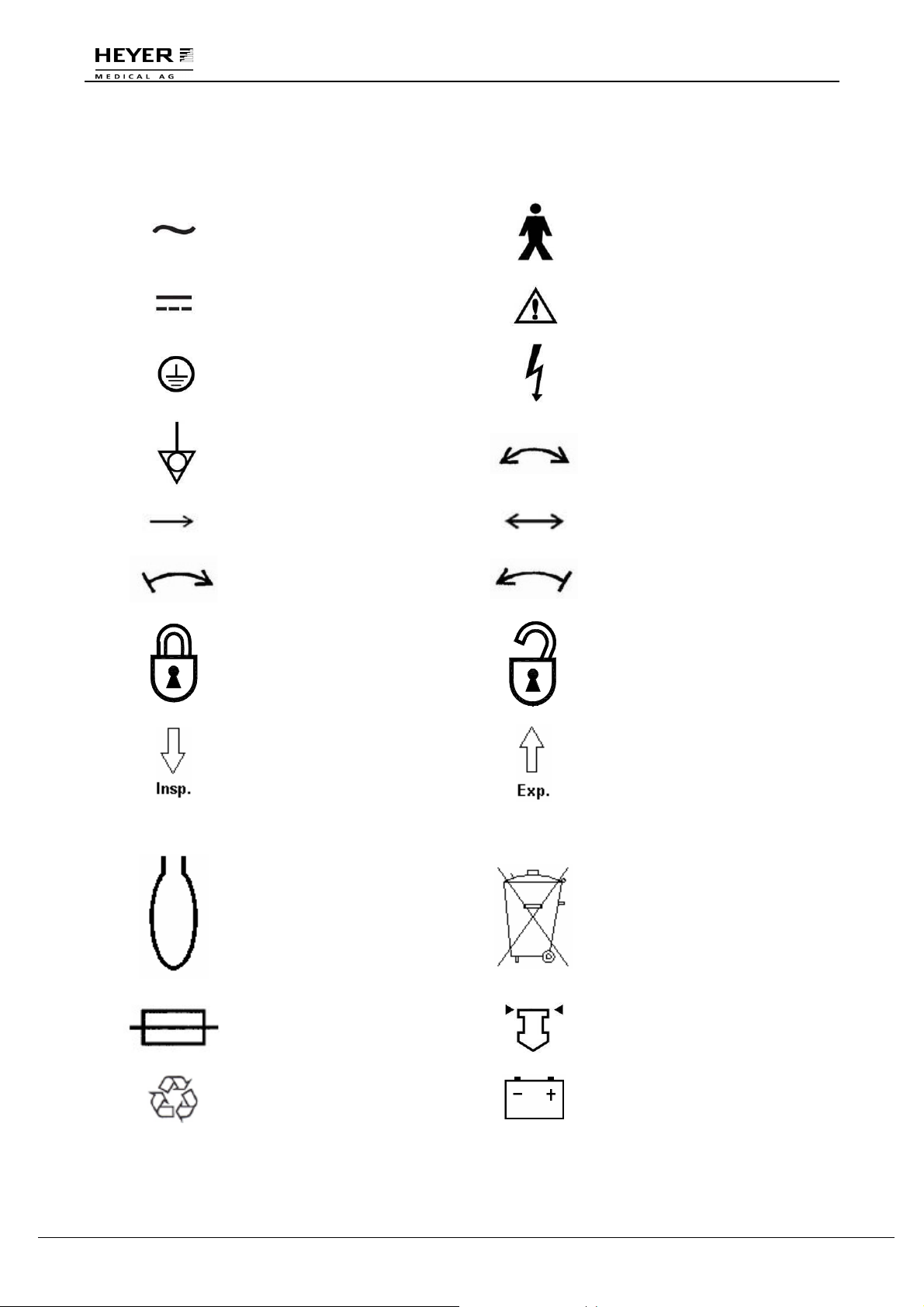
Instead of illustrations, other symbols may also be utilized. Not all of them may necessarily appear in
the equipment and manual. The symbols include:
AC: Alternating current
Type B Applied Part
DC: Direct current
Protective earth
Equipotentiality
Attention: consult
accompanying document
Dangerous Voltage
Rotation in two directions
Movement in one direction
Right-turning movement
Lock
Movement in two directions
Left-turning movement
Unlock
Inspiration flow
Expiration flow
SN Serial Number O2+ O2 flush
Reservoir bag port
Fuse
Recyclable
Do not dispose in garbage
basket.
View the reading on the top
of the float.
Battery
8 / 106 HEYER Pasithec, Operator’s manual Rev. 0.2 Draft - 12/09
Page 9
H E Y E R P a s i t h e c
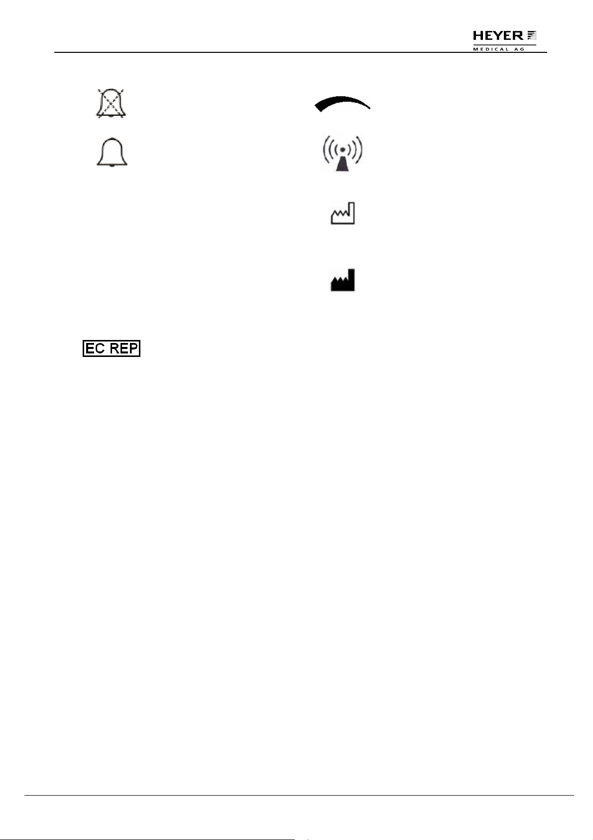
Bell cancel
Bell
△! Alarm, general
△!! Urgent alarm
EC Representative
0
0
00
PENDING
Variability of rotational
adjustment
Non-ionizing
electromagnetic radiation
Date of manufacture
Address of manufacturer
The system, with this label
under the stipulations in the
operating manual, complies
with the requirements
related from 93/42/EEC.
Rev. 0.2 Draft – 12/09 HEYER Pasithec, Operator’s manual 9 / 106
Page 10

H E Y E R P a s i t h e c
2.3 Definition, Abbreviation
AC135 Anesthetic Breathing System
AGSS Anesthetic Gas Scavenging Transfer & Receiving System
APL Adjustable Pressure Limit
BDU Basic Data Unit
C Compliance
C·G·O Common Gas Outlet
cmH2O Centimeters of Water
IPPV Intermittent Positive Pressure Ventilation
EEPROM Electrically Erasable Programmable Read Only Memory
FiO2 Fraction of Inspired Oxygen
Flow-t Flow-time Waveform
Freq Frequency
Freq
Minimum Frequency in PS Mode
MIN
GUI Graphical User Interface
I:E Inspiratory to Expiratory Ratio
L Liter
L/min Liters Per Minute
Manual Manual ventilation
ml Milliliter
MRI Magnetic Resonance Imaging
MV Minute Volume
Paw Airway Pressure
Pb Plumbum
PEAK Peak Pressure
PLAT Plat Pressure
MEAN Mean Pressure
Paw-t Pressure-time Waveform
PCV Pressure Control Ventilation
PEEP Positive End Expiratory Pressure
PIP Peak Inspiratory Pressure
PS Pressure Support Ventilation
P
Target Pressure
TARGET
SIMV Synchronized Intermittent Mandatory Ventilation
T
Inspiratory Time
INSP
TP Inspiratory Pause Time
Trigger Flow Trigger
T
Inspiratory Slope Time
SLOPE
UI User Interface
VT Tidal Volume
WDT Watch Dog Timer
∆P Differential Pressure
Enf. Enflurane
Hal. Halothane
Iso. Isoflurane
Sev. Sevoflurane
Des. Desflurane
ETCO2 End-Expiratory CO2 Concentration
INSCO2 Inspiratory CO2 Concentration
MAC Minimum Alveolar Concentration
10 / 106 HEYER Pasithec, Operator’s manual Rev. 0.2 Draft - 12/09
Page 11

H E Y E R P a s i t h e c
3 System Components
3.1 Anesthetic System
CAUTION: The anesthetic system is intended to be used with the following monitoring
devices, alarm systems, and protection devices:
+ pressure measuring in accordance with 8.1 of ISO 8835-2;
+ system is to be equipped with an ANESTHETIC GAS SCAVENGING
TRANSFER and RECEIVING SYSTEM complying with ISO 8835-3 before
being put into service.
+ pressure limitation device in accordance with 51.101.1 of IEC60601-2-13;
+ exhaled volume monitor in accordance with 51.101.4 of IEC60601-2-13;
+ breathing system integrity alarm system in accordance with 51.101.5 of
IEC60601-2-13;
+ continuing pressure alarm in accordance with 51.101.6 of IEC60601-2-
13;
+ O2 monitor in accordance with ISO 21647.
+ CO2 monitor in accordance with ISO 21647.
+ ANESTHETIC monitor in accordance with ISO 21647.
WARNING: To avoid explosion hazards, flammable anesthetic agents such as Ether and
Cyclopropane shall not be used in the anesthetic workstation. Only use
anesthetic agents that comply with the requirements for non-flammable
anesthetic agents as specified in this manual. Halothane, Desflurane,
Sevoflurane, Enflurane, and Isoflurane have been found to be nonflammable agents.
WARNING: Independent means of ventilation (e.g. a self-inflating manually powered
resuscitator with mask) should be available whenever the anesthetic system
is in use.
WARNING: Do not use antistatic or electrically-conductive breathing tubes and mask.
WARNING: Contact with a liquid, such as anesthetic agent, results in damage within the
device.
WARNING: The incline angle should not exceed 10 degrees whenever the anesthetic
system is in use.
Rev. 0.2 Draft – 12/09 HEYER Pasithec, Operator’s manual 11 / 106
Page 12
H E Y E R P a s i t h e c
2
3
6
1
4
5
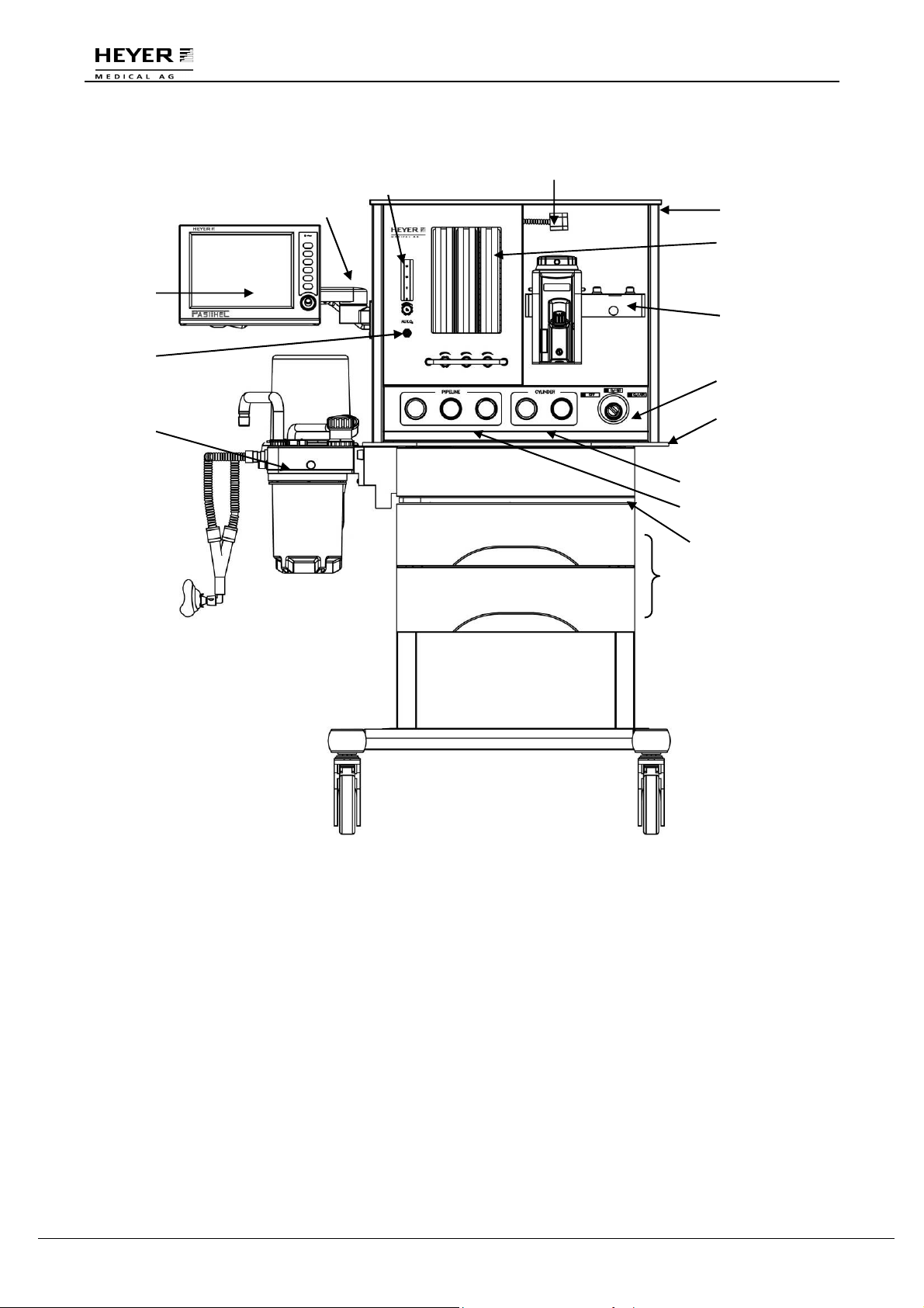
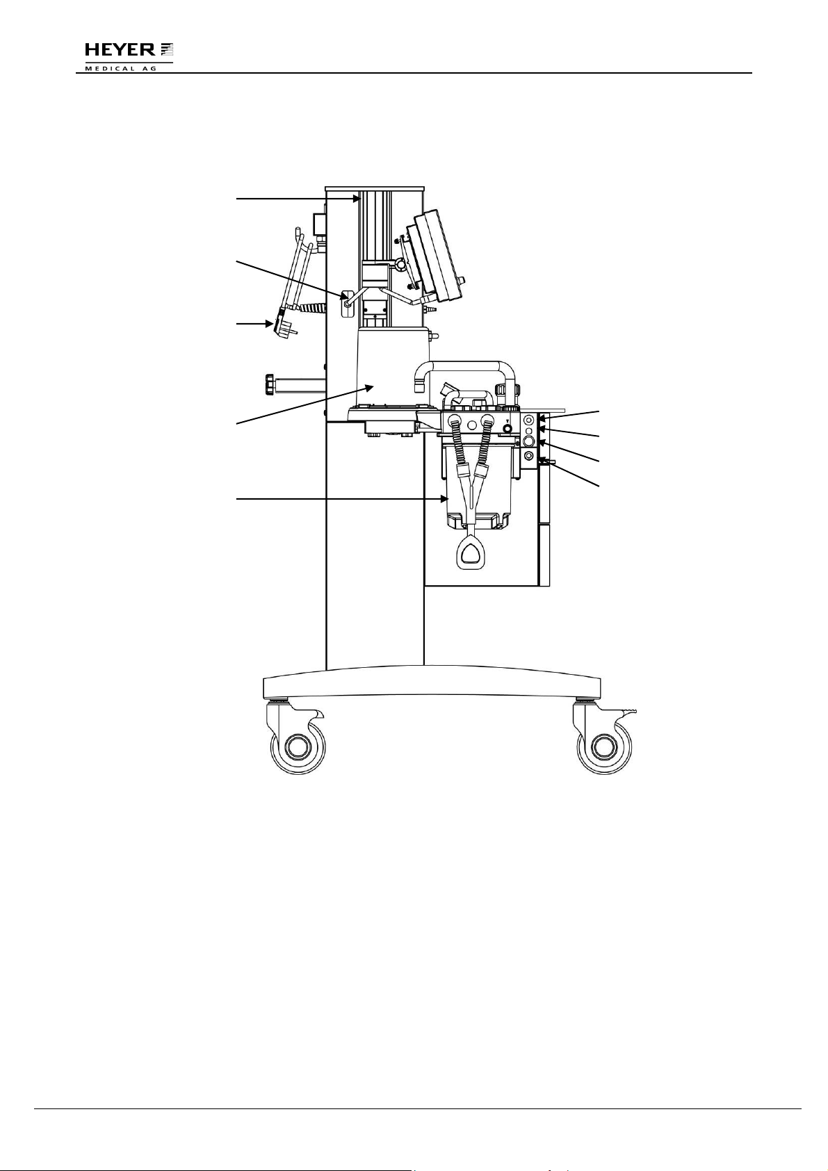
Figure 3-1 Front View
Legend:
1 User Interface (UI) 2 Arm
7
8
9
10
11
12
13
14
15
3 Aux. O2 Flowmeter 4 Aux. O2 Outlet
5 Breathing System 6 Flexible Top Light
7 Top Board 8 Flowmeter
9 Vaporizer Mount 10 Pneumatic and Electronic Switch
11 Main tray 12 Cylinder Pressure Gauges
13 Pipeline Pressure Gauges 14 Pull-out Writing Board
15 Drawers
12 / 106 HEYER Pasithec, Operator’s manual Rev. 0.2 Draft - 12/09
Page 13

H E Y E R P a s i t h e c
assistant power and controller are started with the main switch.
O can enter into flowmeter.
Descriptions of each control function at the front of Pasithec:
Item Description
3 Aux. O2 Flowmeter Provides O2 with a maximal flow of 15 L/min to Aux. O2.
8 Flowmeter with Flow
Control Knobs
Turn the knob counterclockwise to increase the flow; turn
clockwise to decrease the flow.
Reading point is top of float inside flow tube.
6 Top Light The top light will illuminate if top light is switched on. The top light
switch has two settings: on and off.
10 Pneumatic and
Electronic Switch
The switch can control electricity and gas and has three settings.
Electricity main switch: OFF, ON, ON; gas way main switch: OFF,
O2+N2O, O2+Air.
Function of electricity main switch: When system is shut off, the
The machine performs a system self test, and after the test, the
startup is complete. While system is in startup state, turn off the
main switch and be sure the main unit system is closed
completely.
Function of gas way main switch: when switch is in the OFF
position, O2, N2O and AIR cannot enter the flowmeter. When
switch is in O2+N2O position, O2 and N
2
When the switch is in O2+Air position, O2 and AIR can enter.
14 Writing Board The writing board can hold up to 10 kg and can be used by a
doctor during an anesthesia operation.
WARNING: When performing closed or semi-closed ventilation with breathing system,
the Fresh gas switch should be placed to Circle Absorber. Otherwise, there
will be anesthetic gas leakage and abnormal operation of the machine.
Rev. 0.2 Draft – 12/09 HEYER Pasithec, Operator’s manual 13 / 106
Page 14
H E Y E R P a s i t h e c
16
17
18
19
20
Figure 3-2 Side view
Legend:
16 GCX Mounting Rail 17 UI Signal Cable
21
22
23
24
18 Power Cable 19 Bellows Assembly
20 Absorber Circle Assembly 21 O2 Flush (O2+)
22 O2 Sensor Socket 23 Driving Gas Outlet – Switch
24 Driving Gas Outlet (CGO)
14 / 106 HEYER Pasithec, Operator’s manual Rev. 0.2 Draft - 12/09
Page 15

H E Y E R P a s i t h e c
Descriptions of each control function at the side view of Pasithec:
Item Description
21 O2 Flush (O2+) Press the O2 Flush (O2+) button to supply the breathing
system with O2 at a high flow rate.
22 O2 Sensor Socket Socket to connect Oxygen Sensor for monitoring oxygen
concentration of absorber circle. When monitoring patient
oxygen concentration in inspiratory gas at the back of
inspiratory valve, the socket can be selected.
23 / 24 Driving Gas Outlet (Switch) Provide driving gas to other equipment. Pressure: 280
kPa~600 kPa, flow: max. 90 L/min.
Rev. 0.2 Draft – 12/09 HEYER Pasithec, Operator’s manual 15 / 106
Page 16
H E Y E R P a s i t h e c
25 26 27 28
29
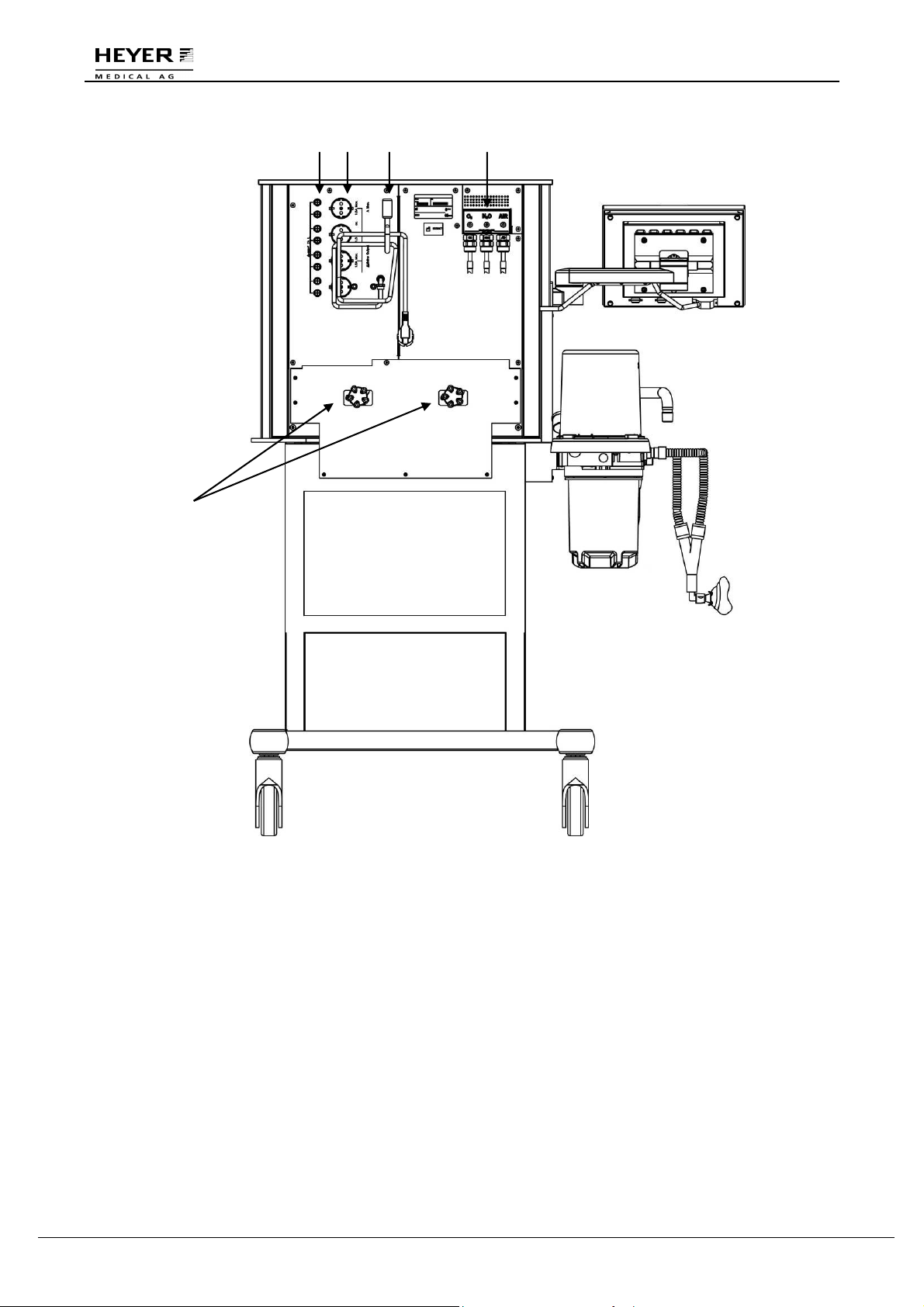
Figure 3-3 Rear View
Legend:
25 Fuses 26 Aux. Power Sockets
27 Power Cable 28 Pipeline Gas Inlet Module
29 Gas Cylinder Yokes
16 / 106 HEYER Pasithec, Operator’s manual Rev. 0.2 Draft - 12/09
Page 17
H E Y E R P a s i t h e c
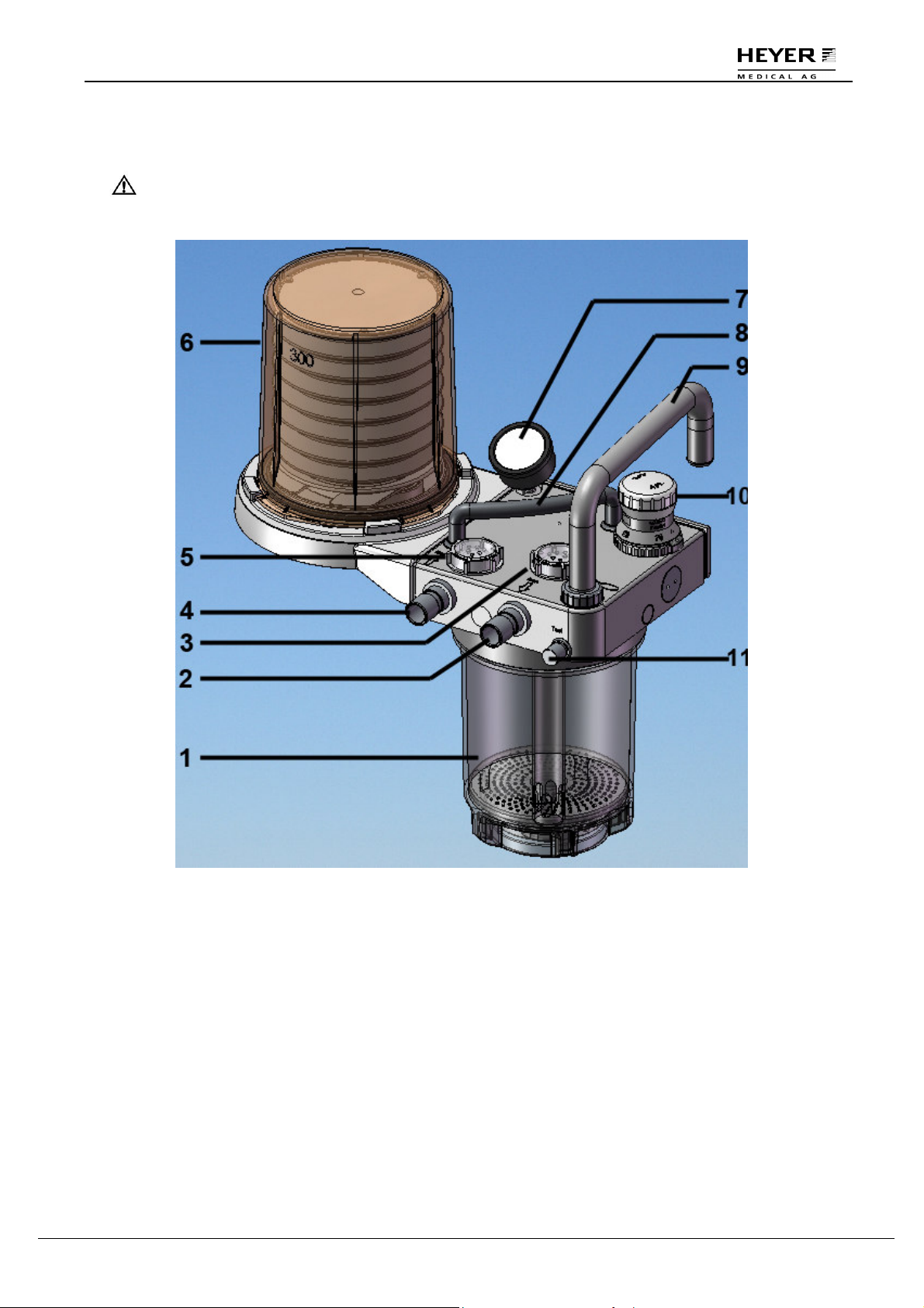
3.2 Breathing System
CAUTION: The breathing system used together with the anesthetic gas supply system
shall be in accordance with ISO 8835-2.
Figure 3-4 Breathing System
Legend:
1 Absorber Canister 2 Inspiratory Port
3 Inspiratory Valve 4 Expiratory Port
5 Expiratory Valve 6 Bellows
7 Airway Pressure Gauge 8 Handle
9 Bag Arm 10 APL valve
11 Test Block
Rev. 0.2 Draft – 12/09 HEYER Pasithec, Operator’s manual 17 / 106
Page 18
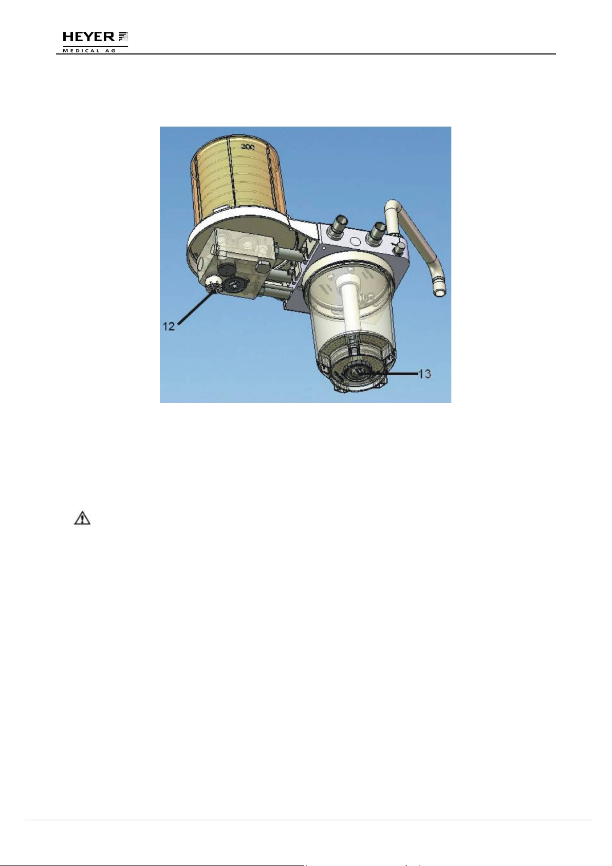
3.2.1 Bellows Assembly Ports
H E Y E R P a s i t h e c
Figure 3-5 Ports of bellows assembly
12 Exhaust Gas Port
13 Nut (drain plug): Loosen the nut to drain the water when absorbent (natrium lime)
in absorber has been commixed with water.
WARNING: Never connect exhaust gas port with sub-atmospheric system directly, as it
results breathing system leakage.
Do not block exhaust gas port.
18 / 106 HEYER Pasithec, Operator’s manual Rev. 0.2 Draft - 12/09
Page 19
H E Y E R P a s i t h e c
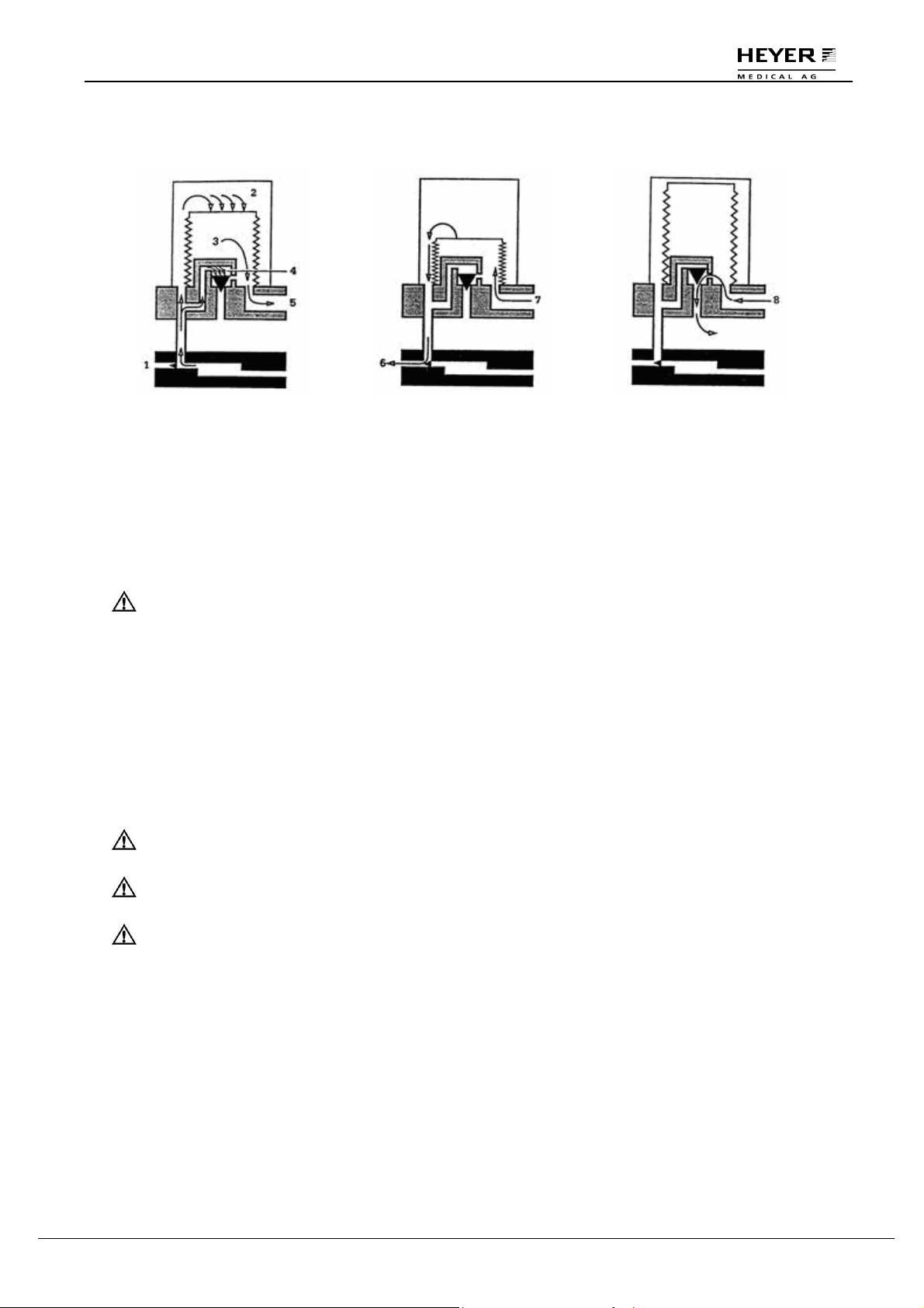
3.2.2 Ventilating Circulation
Inhalation Primary Phase:
1 Exhalation Valve
2 Driving Gas
3 Gas of Patient Circuit
4 Pressure-Relief Valve
5 To Patient Circuit
Exhalation Primary Phase:
6 Driving Gas
7 From Patient Circuit
Exhalation End Phase:
8 Excess Gas from Patient
Circuit
3.3 Vaporizer
CAUTION: The vaporizer used with the anesthetic system shall comply with ISO
8835-4.
A checklist for the assembly of the anesthetic system from individual components shall be
provided by the assembler of the anesthetic system.
For more detailed information about the vaporizer, please refer to the instructions for the vaporizer
when used in the anesthetic system.
3.4 Anesthetic Ventilator
CAUTION: Anesthetic ventilator used in anesthetic system shall comply with ISO 8835-
5.
CAUTION: Monitoring conditions of this system: Ambient temperature: 25°C; Air
temperature: 25°C; Air humidity: 30%; Gas component : O2.
CAUTION: If the temperature of O2 sensor is lower than dew point of breathing gas,
vapor may coagulate on the surface of the sensor and oxygen
concentration on the monitor may be lower than the practice value.
Rev. 0.2 Draft – 12/09 HEYER Pasithec, Operator’s manual 19 / 106
Page 20
H E Y E R P a s i t h e c
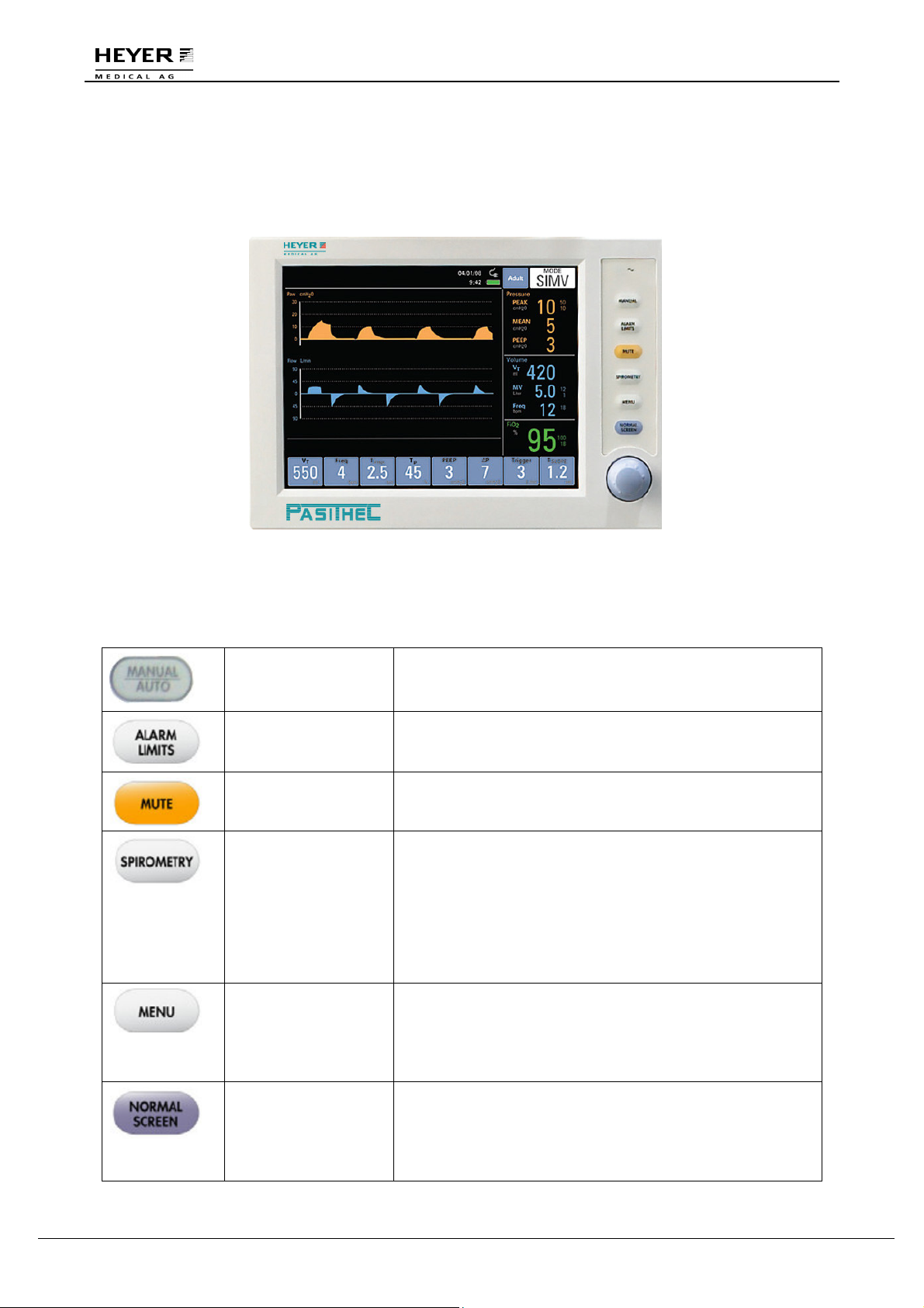
3.4.1 Front Panel
Front panel consists of display screen, keys, indicators, and a knob.
Figure 3-6 Front Panel
3.4.2 Keys
Manual Key Press the key to change original ventilation mode to manual
mode; Press again to change back to the original ventilation
mode.
Alarm Limits Key
MUTE Key
Spirometry Key This key shall toggle the display between the waveform
MENU Key Press the key and a “Menu” window appeared on the
Normal screen Key The key closes the “Spirometry” and other windows and
Press the key to open alarm window on the screen; Press
again to close the alarm window.
Press the key to mute the alarm for 110 seconds. New
alarms shall override the mute.
window and the two loop display configurations of the
Spirometry Loop Window described in section 4.5. The first
key press shall display the “Pressure-Volume” loop display
configuration. The second key press shall display the “FlowVolume” loop display configuration. After both
configurations have been cycled through the display, a third
key press shall return the display to the Normal Screen.
display screen; for more details refer to section 3.5.
The first menu key press after the initial power up will
display the calibrate menu, with “Start Calibration”
highlighted.
returns the screen to pressure and flow waveforms.
If the “Spirometry” and all other windows are already closed
when the NORMAL SCREEN key is pressed again, no
action shall occur.
20 / 106 HEYER Pasithec, Operator’s manual Rev. 0.2 Draft - 12/09
Page 21
H E Y E R P a s i t h e c
3.4.3 Indicator
AC indicator The indicator lights up when AC power is in use;
the indicator is dark when the AC power fails.
3.4.4 Navigator Knob
The user can adjust the rotary knob to select the menu item and modify the setup. It can be rotated
clockwise or counter-clockwise and pressed like other buttons. The knob may be used to select
options on the screen, in the system menu, and in the parameter menu.
The rectangular mark on the screen that moves with the rotation of the knob is the “cursor”. The
cursor can be used to select any menu item on which it lands.
Operating method:
Move the cursor to the item you wish to select
Press the knob
One of the following four situations will happen:
If the background color of the cursor becomes a contrasting color, the content in the
frame can change with the rotation of the knob.
A pull down menu or dialogue box may appear on the screen
The original menu will be replaced by the new menu.
Save setup
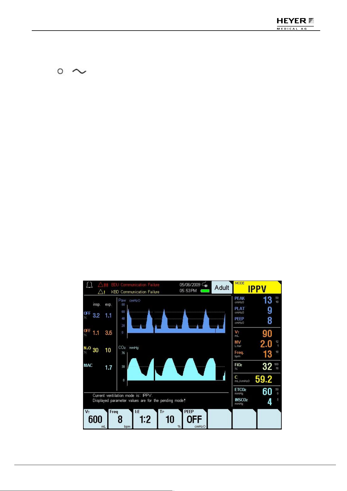
3.4.5 Screen Layout
The display of the ventilator is a color TFT, which can display the monitoring and setting parameters,
waveforms, and alarm information on the screen. See Fig. 3-7.
The screen has three areas: information area, monitoring area, and parameter setup area.
Figure 3-7 Display screen layout
Rev. 0.2 Draft – 12/09 HEYER Pasithec, Operator’s manual 21 / 106
Page 22

H E Y E R P a s i t h e c
3.4.5.1 Information Area
The information area is divided into seven areas: Alarm Indication, Alarm Messages, Date, Time,
Power Source, Patient Type and Ventilation Mode.
3.4.5.1.1 Alarm Indication
The bell icon is displayed when an alarm is present. When it appears, the color of alarm bell is white.
Pressing the alarm mute key places an “X” on the alarm bell icon for 110 seconds. Displayed below
the bell icon is a countdown timer that will display remaining silence time.
3.4.5.1.2 Alarm Messages
Technical Messages and Functional Alarm will be displayed in the alarm message area. High priority
alarms will be red. Mid- and low-priority alarms will be yellow. Up to 2 alarm messages can be
displayed on the screen. For more details, refer to Chapter 9.
3.4.5.1.3 Power Source
Located the left of Ventilation Mode tile are two icons: AC and Battery. The display status of the
Battery includes: Full, Charging and Exhausted. The display status of the AC includes: AC power up
and AC power down.
AC power up: (1) The Battery icon is solid and at 100% capacity when fully charged. (2) If in charging,
the Battery icon shows capacity alternately.
AC power down: (1) The Battery icon shows the current capacity. (2) The Battery can supply power for
the machine for about 15 minutes when the low battery alarm sounds.
3.4.5.1.4 Date
The display mode of Date has three types: MM/DD/YY, DD/MM/YY or YY/MM/DD.
3.4.5.1.5 Time
The display mode of Time has 2 types: 12 hour or 24 hour format.
3.4.5.1.6 Patient Type
The patient type shall be displayed as Adult or Child. By highlighting (black text on white background)
the Patient type tile and pressing, the navigator knob shall toggle the patient type between Adult and
Child. Changing patient type is possible in STANDBY mode only. The default patient type when the
machine is powered up is Adult.
3.4.5.1.7 Ventilation Mode
Pressing the navigator knob when the Mode tile is highlighted displays the current ventilation mode in
white text on a black background, and the “MODE” label remains displayed in black text on a green
background. Rotating the navigator knob clockwise allows the user to scroll through the ventilation
mode selections: STANDBY, IPPV, PCV, SIMV, PS and MANUAL. Rotating the navigator knob
counterclockwise allows the user to scroll through the settings in the reverse order. The default mode
when the machine is powered up is standby.
22 / 106 HEYER Pasithec, Operator’s manual Rev. 0.2 Draft - 12/09
Page 23

H E Y E R P a s i t h e c
3.4.5.2 Monitoring Area
The monitoring area has two parts: Patient waveform and parameters. See Fig. 3-7.
3.4.5.3 Parameters Setup Area
The parameter setup area contains 8 tiles of fixed vertical height and fixed horizontal width; each tile
contains the tile’s parameter value.
Each tile represents a location that may be highlighted by the navigator knob. Current parameter
settings are displayed in reverse video in the parameter window when a parameter tile is highlighted
(black text on white background). Rotating the navigator knob clockwise allows the user to increase
the setting while rotating the knob counterclockwise decreases the setting. When the selection
reaches its maximum or minimum setting, the minimum or maximum setting is displayed.
Pressing the navigator knob selects the parameter setting which is displayed as white text within a
black field. Parameter settings shall be in normal video unless the parameter tile has been selected or
highlighted. Parameter tiles are populated per table 3-1 below.
A timeout shall occur when a parameter tile is selected or changed but not confirmed for 15 seconds.
Upon a timeout, the parameter setting reverts back to the previously confirmed value.
The parameter timeout shall be available for the following items:
• Ventilation Mode
• Patient Type
Table 3-1
In the following table ”Para.” is equated with “Parameter”.
Vent Mode
Para.
Setup 1
Para.
Setup 2
Para.
Setup 3
Para.
Setup 4
Para.
Setup 5
Para.
Setup 6
Para.
Setup 7
Para.
Setup 8
STANDBY Blank Blank Blank Blank Blank Blank Blank Blank
IPPV VT Freq. I:E TP PEEP Blank Blank Blank
PCV P
SIMV VT Freq. T
PS Blank Freq
MANUAL /
AUTO
Blank Blank Blank Blank Blank Blank Blank Blank
Freq. I:E Blank PEEP Blank Blank T
TARGET
TP PEEP ∆P Trigger T
INSP
Blank Blank PEEP ∆P Trigger T
MIN
SLOPE
SLOPE
SLOPE
Rev. 0.2 Draft – 12/09 HEYER Pasithec, Operator’s manual 23 / 106
Page 24
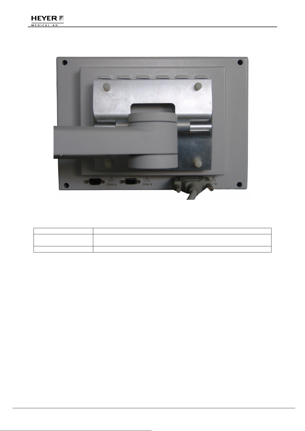
3.4.6 Rear Panel
H E Y E R P a s i t h e c
Figure 3-8 Rear Panel
Legend:
COM A Interface Communication extension interface communicates with the IRMA.
COM B Interface Communication extension interface is used for connecting external
communication equipment (RS232 interface).
SIGNAL Interface Signal interface is used for connecting display screen to main unit.
24 / 106 HEYER Pasithec, Operator’s manual Rev. 0.2 Draft - 12/09
Page 25
H E Y E R P a s i t h e c
3.5 Menu
3.5.1 Operating Guide
When calibrating or carrying out other functions, an explanation of the process will be displayed on the
screen.
The following diagram is an example.
Step 1
When the MENU key is pressed, a “Menu” window is displayed on the screen.
Note: The “Menu” window opens in the last viewed menu.
The following example illustrates how to operate the settings.
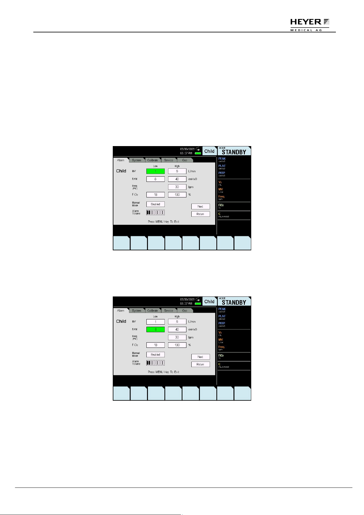
Step 2
Turn the knob to select the Paw-Low option; the selected option will appear as black text on a green
background.
Rev. 0.2 Draft – 12/09 HEYER Pasithec, Operator’s manual 25 / 106
Page 26
H E Y E R P a s i t h e c
Step 3
Press the knob to enter the setting; the background will appear as white text on a black background.
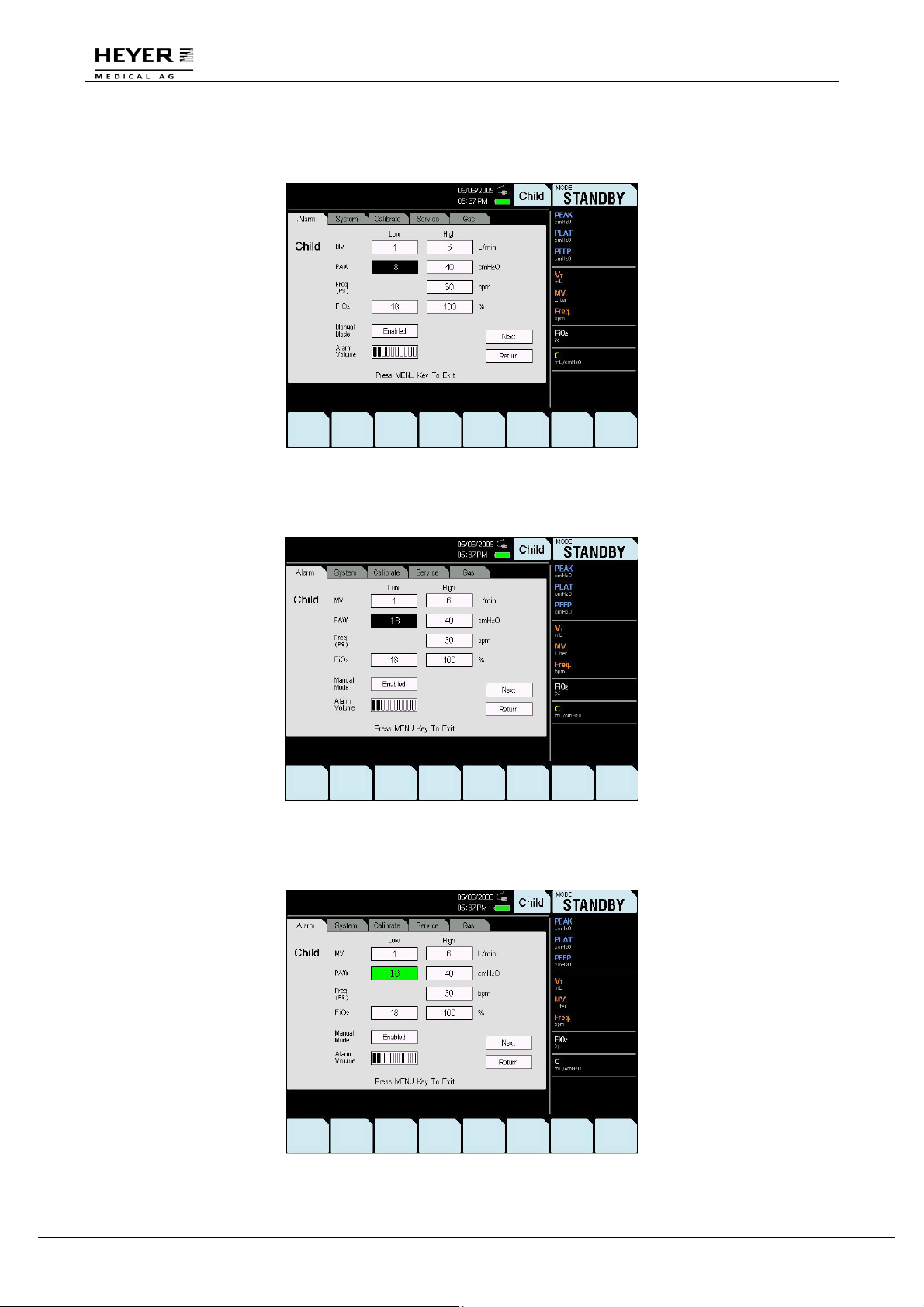
Step 4
Turn the knob to select the setting.
Step 5
Press the knob to save the setting; the background will appear as black text on a green background.
26 / 106 HEYER Pasithec, Operator’s manual Rev. 0.2 Draft - 12/09
Page 27
H E Y E R P a s i t h e c
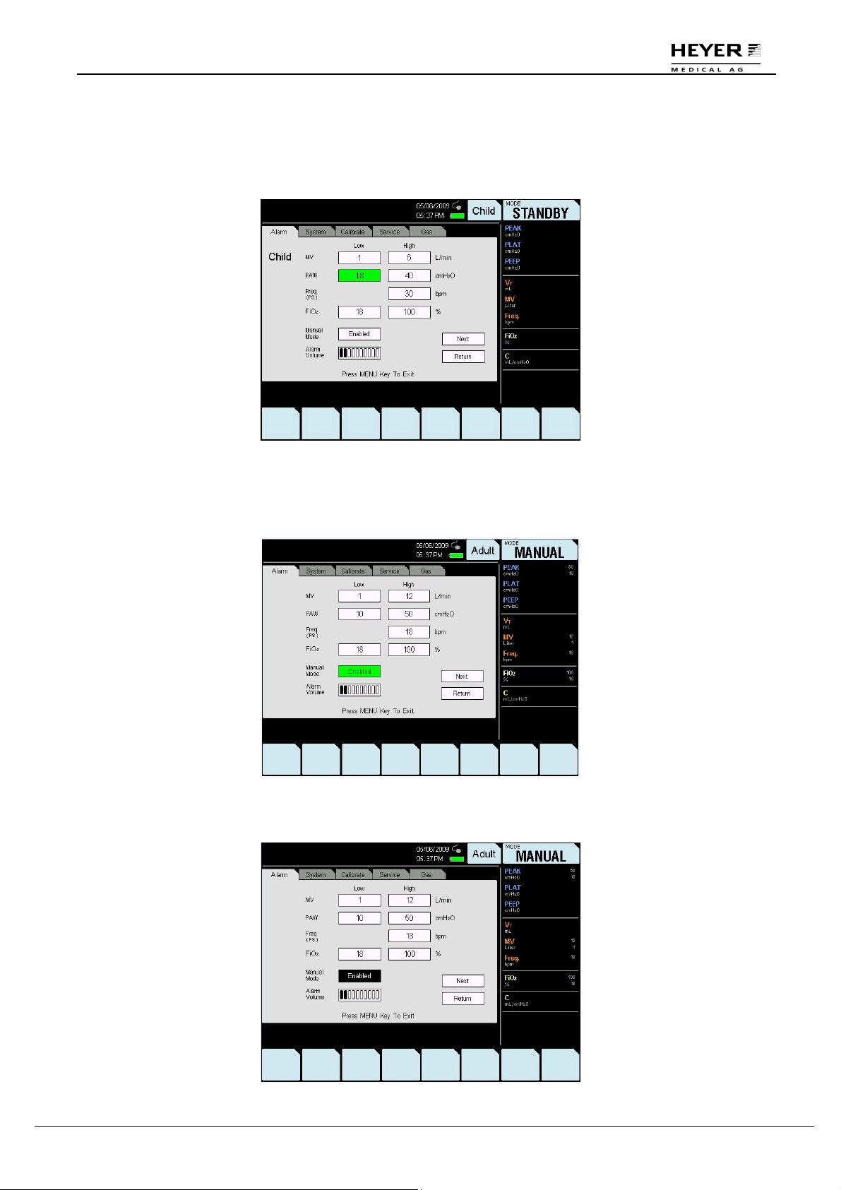
Step 6
Turn the knob and select “Return” to set other parameters. Follow the above directions to select the
corresponding submenu.
Press the MENU key to exit the screen.
The default alarm setting in the manual mode is “Enabled”. To adjust the setting:
Step 1: Select “Manual Mode.”
Step 2: Press the knob.
Rev. 0.2 Draft – 12/09 HEYER Pasithec, Operator’s manual 27 / 106
Page 28
H E Y E R P a s i t h e c
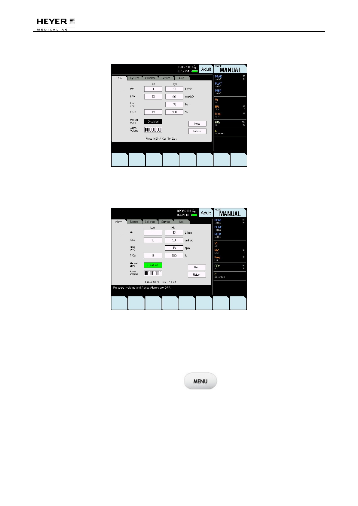
Step 3: Turn the knob to display “Disabled.”
Step 4: Press the knob to save the “Disabled” setting.
The patient’s pressure, tidal, and asphyxiation alarms will not be displayed.
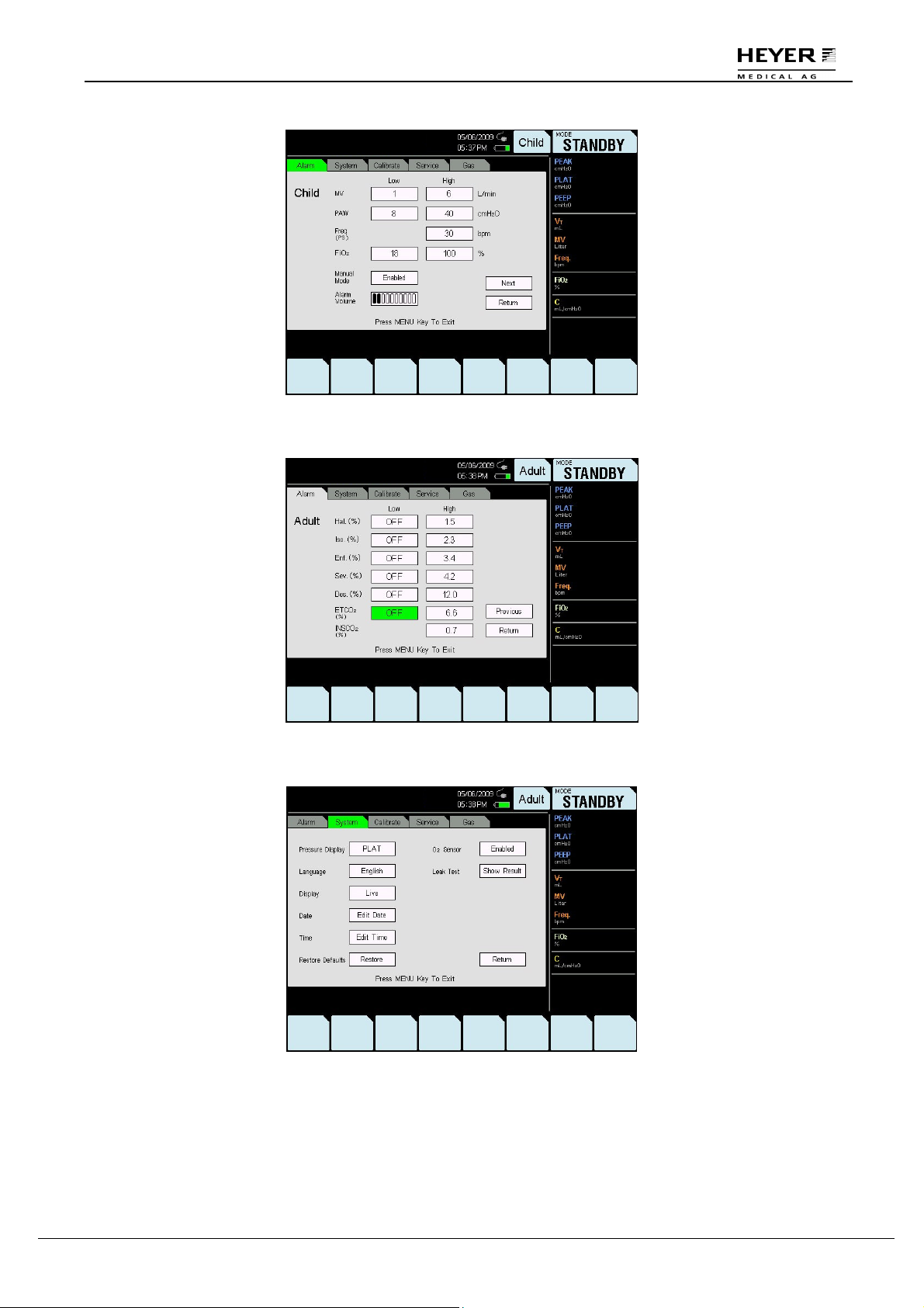
3.5.2 Menu Diagram
Figure 3-9 to
Figure
3-13
displays each submenu in the Menu window. Some functions are optional.
When you press the MENU key, the “Menu”
window is displayed on the screen.
Turn the knob to select a submenu.
28 / 106 HEYER Pasithec, Operator’s manual Rev. 0.2 Draft - 12/09
Page 29
H E Y E R P a s i t h e c
Figure 3-9 Alarm submenu (Page 1)
Figure 3-10 Alarm submenu (Page 2)
Figure 3-11 System submenu
Rev. 0.2 Draft – 12/09 HEYER Pasithec, Operator’s manual 29 / 106
Page 30
H E Y E R P a s i t h e c
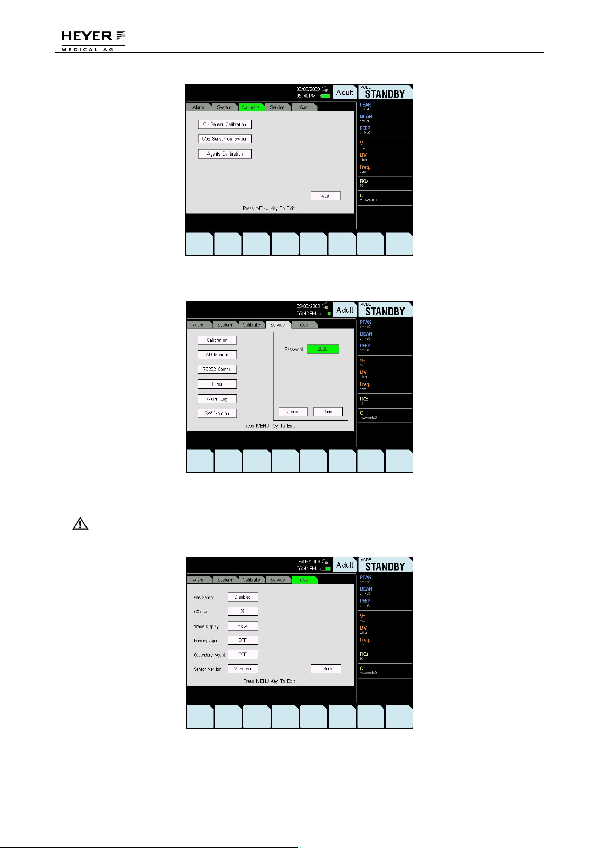
Figure 3-12 Calibrate submenu
Figure 3-13 Service submenu
CAUTION: A password is needed for the Service submenu. Only an authorized
engineer can access this submenu.
Figure 3-14 Gas submenu
30 / 106 HEYER Pasithec, Operator’s manual Rev. 0.2 Draft - 12/09
Page 31

H E Y E R P a s i t h e c
Gas Sensor
When the gas sensor is in “Enabled” mode, the sensor was properly connected to the machine and
can be used.
When the gas sensor is in “Disabled” mode, it was not properly connected prior to starting the
machine and cannot be used.
The Gas Sensor settings can be adjusted by following these instructions:
Step 1: Turn the knob to select “Gas Sensor.”
Step 2: Press the knob, and then turn it to change the settings.
Rev. 0.2 Draft – 12/09 HEYER Pasithec, Operator’s manual 31 / 106
Page 32

H E Y E R P a s i t h e c
Step 3: Press the knob to save the setting.
When the Wave Display is in “Flow” mode, flow-time wave is displayed.
When the Wave Display is in “CO2” mode, CO2-time wave is displayed.
The Wave Display default setting is “Flow” when the machine is turned on.
To adjust Wave Display settings, follow these instructions:
Step 1: Turn the knob to select “Wave Display.”
Step 2: Press the knob, and then turn it to change the setting.
32 / 106 HEYER Pasithec, Operator’s manual Rev. 0.2 Draft - 12/09
Page 33

H E Y E R P a s i t h e c
Step 3: Press the knob to save the setting.
Rev. 0.2 Draft – 12/09 HEYER Pasithec, Operator’s manual 33 / 106
Page 34

H E Y E R P a s i t h e c
4 Operating Guide
4.1 Startup
Step 1: Connect Main Supply and Gas Supply
Plug the power cord into the AC power outlet and connect the pipeline gas supply and standby gas
supply. Turn on the cylinder valve of the standby gas supply and turn off the flowmeters of O2, N2O,
Air, and Aux. O2.
Step 2: Turn on the Power Switch
Turn the Power Switch to “ON”. The UI will power on and perform a System Self Test.
4.1.1 System Self Test
When the UI is powered on, the startup interface is displayed, followed by the LOGO interface.
Figure 4-1 LOGO Interface
The System Self Test interface will appear after the LOGO interface.
Figure 4-2 System Self Test Interface
34 / 106 HEYER Pasithec, Operator’s manual Rev. 0.2 Draft - 12/09
Page 35

H E Y E R P a s i t h e c
The System Self Test Complete interface will appear when the self test is complete.
Figure 4-3 System Self Test Complete interface
Select the “Continue” option to perform the Leak Test procedure.
Select “Bypass” to enter the STANDBY interface.
If the self test fails, please contact a service representative.
Rev. 0.2 Draft – 12/09 HEYER Pasithec, Operator’s manual 35 / 106
Page 36

H E Y E R P a s i t h e c
4.1.2 Manual Leak Test
The Leak Test includes verification of APL valve and Flowmeter. Click “Continue” to begin the leak
test. See Figure 4-4 below.
Figure 4-4 Setup before Manual Leak Test
Perform the following according to the prompts in the above figure:
1. Connect the Y-piece to Test Port “T”.
2. Install the Manual Bag.
3. Adjust APL valve to 30 cmH2O.
4. Adjust all flowmeters to zero.
5. Set Fresh Gas switch to Circle absorber.
6. Select “Continue”.
Figure 4-5 Manual Leak Test
Perform the manual leak test according to the instructions pictured in Figure 4-5:
1. Push O2 flush button until Paw gauge value is between 25 cmH2O and 35 cmH2O.
2. Verify that bellows did not move while performing step 1.
3. If bellows moved during step 1, turn off Power Supply and contact manufacturer.
4. Select “Continue” if Paw gauge index is between 25 cmH2O and 35 cmH2O.
36 / 106 HEYER Pasithec, Operator’s manual Rev. 0.2 Draft - 12/09
Page 37

H E Y E R P a s i t h e c
4.1.3 Safety Valve Test
Click the “Continue” to perform Safety Valve Test as shown in Figure 4-6:
Figure 4-6 Safety Valve Test in progress.
When test is complete, screen will display the following:
Figure 4-7 Safety Valve Test Pass interface
Rev. 0.2 Draft – 12/09 HEYER Pasithec, Operator’s manual 37 / 106
Page 38

H E Y E R P a s i t h e c
4.1.4 Automatic Leak Test
When the Safety Valve Test is complete, the Automatic Leak Test is displayed on the screen.
Figure 4-8 Automatic Leak Test
Click “Continue” to perform the Leak Test.
Figure 4-9 Automatic Leak Test in progress
When the leak test is complete, the following is displayed:
Figure 4-10 Automatic Leak Test Pass interface
38 / 106 HEYER Pasithec, Operator’s manual Rev. 0.2 Draft - 12/09
Page 39

H E Y E R P a s i t h e c
4.1.5 Compliance Test
Click “Continue” to perform the Compliance Test.
Figure 4-11 Compliance Test
Perform the Compliance Test according to the instructions pictured in Figure 4-11:
1. Set O2 flow to 5 L/min.
2. Select “Continue” to start test or select “Bypass” to proceed to Normal Screen.
Click “Continue” option to perform the Compliance Test.
Figure 4-12 Compliance Test in Progress
Rev. 0.2 Draft – 12/09 HEYER Pasithec, Operator’s manual 39 / 106
Page 40

H E Y E R P a s i t h e c
The following will appear after the Compliance Test is complete:
Figure 4-13 Compliance Test Complete interface
Complete the Compliance Test according to the instructions shown in Figure 4-13:
1. Set O2 flowmeter to zero.
2. Select “Continue” to proceed to Normal Screen.
Click “Continue” and the STANDBY screen will appear:
Figure 4-14 STANDBY interface
40 / 106 HEYER Pasithec, Operator’s manual Rev. 0.2 Draft - 12/09
Page 41

H E Y E R P a s i t h e c
4.1.6 Ventilation Mode Setup
The current Ventilation mode is shown at top right
corner of the display, with the arrow pointed up.
STANDBY mode
IPPV mode
PCV mode
SIMV mode
PS mode
Manual mode
Step 1: Turn the knob and point the cursor to the current ventilation mode.
CAUTION Exit the menu before carrying out this step.
Step 2: Press the knob to ensure the grounding changed.
Step 3: Turn the knob to select the required ventilation mode.
Step 4: Press the knob for the pre-election state; setting parameters can then be changed.
Step 5: Point cursor to the ventilation mode and press the knob to save the setup.
4.1.7 Breathing Parameters Setup
Step 1: Turn the knob and point the cursor to the corresponding parameter.
CAUTION: Exit the menu before carrying out this step.
Step 2: Press the knob to ensure the grounding changed.
Step 3: Turn the knob to select the required ventilation mode.
Step 4: Press the knob to save the setup.
4.2 Start Mechanical Ventilation
WARNING: Before beginning, set the patient circuit installing and controlling correctly.
The following procedures assume that the system is on and the manual
reservoir gas is in ventilating mode.
Step 1: Check that the control settings coincide with the clinical settings.
Step 2: Select “Auto Ventilation”. To adjust settings, refer to section 4.1.6.
Step 3: If necessary, push the O2 flush button to inflate the bellows.
4.2.1 Stop Mechanical Ventilation
Set ventilation mode to Manual or STANDBY mode.
Rev. 0.2 Draft – 12/09 HEYER Pasithec, Operator’s manual 41 / 106
Page 42

H E Y E R P a s i t h e c
4.3 Start Manual Ventilation
Step 1: Before starting manual ventilation, connect the reservoir bag to the gas operation port and
ensure the APL valve setting is correct. The APL valve is used to adjust the pressure limit of the
breathing system during the manual ventilation period.
Step 2: Set the ventilation mode to “Manual”, or press the “MANUAL/AUTO" key. To use the reservoir
bag to perform manual ventilation if necessary, push the O2 flush button to inflate the reservoir bag.
4.3.1 Stop Manual Ventilation
Set Ventilation Mode to STANDBY mode.
Manual ventilation can also be stopped by not pinching the reservoir bag or by pressing the
“MANUAL/AUTO" key, which will revert the system to mechanical ventilation.
4.4 Shutdown
Turn off gas supply and set the ventilation mode to “Standby” after the gas within the system is
emptied. Turn off the power.
4.5 Waveforms
1. Paw-t Waveform
Y-Axis: airway pressure; X-Axis: time. For more details, refer to section 10.8.6.
Figure 4-15 Paw-t waveform
2. Flow-t Waveform
Flow scale: -90~90 L/min.
Time-Axis: Positive inspiratory direction above 0 L/min level; minus expiratory direction below 0 L/min
level; no gas flow on 0 L/min level.
Figure 4-16 Flow-t waveform
42 / 106 HEYER Pasithec, Operator’s manual Rev. 0.2 Draft - 12/09
Page 43

H E Y E R P a s i t h e c
3
....
CO2- t Waveform
Y-Axis: CO2; X-Axis: time.
4. Pressure-Volume Loop
Y-Axis: tidal volume; X-Axis: pressure.
Figure 4-17 CO2- t waveform
Figure 4-18 Pressure-Volume Loop
Rev. 0.2 Draft – 12/09 HEYER Pasithec, Operator’s manual 43 / 106
Page 44

H E Y E R P a s i t h e c
5. Flow-Volume Loop
Y-Axis: flow; inspiratory flow above 0 L/min level; expiratory flow below 0 L/min level.
X-Axis: tidal volume.
Figure 4-19 Flow-volume Loop
The “Save Reference” option can be used to preserve a loop for future reference. When a loop is
currently being displayed, or no loop is currently being displayed, Press “Save Reference” when either
a loop is currently being displayed or no loop is being displayed, and the next complete loop
(inspiration and expiration) will be saved as a reference.
After “Save Reference” is pressed down, the Pressure-Volume loop and Flow-Volume loop are
simultaneously preserved.
When “Save Reference” is pressed again, the system immediately deletes the current preserved
Pressure-Volume loop and Flow-Volume loop and preserves the two new reference loops.
When a user exits the loop function, the preserved loops are saved. When the working mode is
STANDBY, the two function loops are deleted.
44 / 106 HEYER Pasithec, Operator’s manual Rev. 0.2 Draft - 12/09
Page 45

H E Y E R P a s i t h e c
5 Pre-use Check List
5.1 Pre-use Check List Procedure
Test interval: Pre-operative Checkout should be done each day prior to use by the first patient; prior
to the use of each subsequent patient, and after repair or maintenance.
The test schedule appears in the table below:
Prior to use by the first patient each day Prior to use by each patient
System check
Power failure alarm test
Gas pipeline and gas cylinder test
Flow control test
Vaporizer installation and test
Alarm test
Breathing system test
Ventilator test
WARNING: Do not use this system until the operation and maintenance manuals have
been read and understood.
•
Whole system connection
•
All warnings and cautions
•
User guide for each system module
•
Testing method for each system module
Before using this system:
Complete all tests of this section
Test all system modules
If a test fails, do not use this system. Please contact a service representative.
5.1.1 Check System
Breathing System test
Ventilator test
WARNING: Ensure the breathing circuit is connected correctly and in good condition.
Make sure:
1
Equipment is in good condition.
2
All the components are correctly connected.
3
Breathing circuit is correctly connected and in good condition and the breathing system contains
sufficient absorbent.
4
Vaporizer is in lock position and is filled with sufficient anesthetic.
5
The connection and pressure of pipeline gas supply system are correct.
WARNING: Do not leave the cylinder valves open during pipeline gas supply period.
The cylinder gas supply could be emptied and lead to insufficient supply in
case of pipeline malfunction.
6
The required emergency device is ready and in good condition.
7
The device for airway maintenance and organ cannula are ready and in good condition.
8
The applicable anesthetic and emergency medicine are ready.
9
Tighten and lock the truckles to ensure they are free of motion.
10
Connect the power cord to the AC power outlet. The power indicator light will glow when power is
connected. If the indicator does not glow, power is not being supplied to the machine. Plug the
power cord into a different socket, close the breaker, or replace the power cord.
Rev. 0.2 Draft – 12/09 HEYER Pasithec, Operator’s manual 45 / 106
Page 46

H E Y E R P a s i t h e c
5.1.2 Main Failure Alarm Test
1
Turn on the power. Screen will display the stand-by interface after running the self-test.
2
After 5 minutes, unplug the power cord.
3
Check the “Power Off Failure Alarm”; it has the following characteristics:
a) Alarm sounds
b) “Mains Failure!” message displays on the screen
c) Mains icon flickers
4
Reconnect power cord.
5
Alarm will stop.
5.2 Test Gas Supply Pipeline
CAUTION: A user must confirm that gas supply is connected correctly. The pressure
should be correct and there should be no leakages or faulty connections in
the gas circuits. Stop using immediately and check gas connections if any
of the above occur.
Disconnect all pipeline gas supplies if the reading of the pipeline pressure gauge is not zero.
•
Switch on O2 supply.
•
Adjust flow control to middle range.
•
Make sure the N2O pressure gauge is reset to zero.
•
Switch off O2 supply.
•
Make sure the O2 pressure gauge is reset to zero. The low O2 supply alarm should
sound when pressure drops.
5.3 Monitoring Flow Control
WARNING: Refer to Step 1 to 14 of Monitoring without Oxygen for monitoring without
oxygen.
Refer to Step 1 to 13 of Monitoring with Oxygen for monitoring with oxygen.
5.3.1 Monitoring without Oxygen
WARNING: The monitoring system cannot be replaced by a link system. A fresh supply
of gas that contains oxygen may not sufficiently increase the level of
oxygen in the breathing circuit.
If N2O exists, it will pass through the system during the test, which should
be securely collected and removed.
Patients may be injured by improper gas mixture. The link system should
not be used if a proper ratio of O2 and N2O is not possible.
The following procedures can test whether the link system has serious
malfunction; however, it cannot determine whether the calibration is
correct.
CAUTION: The gas flow control valve should be adjusted slowly. Do not turn it quickly
when the reading of the flowmeter goes beyond the maximum or minimum
flow rate; the control valve could be damaged and/or break.
46 / 106 HEYER Pasithec, Operator’s manual Rev. 0.2 Draft - 12/09
Page 47

H E Y E R P a s i t h e c
Follow the steps to test the flow control:
1. Connect the pipeline gas supply or open the cylinder valves slowly.
2. Turn counter-clockwise O2, N2O, AIR flow control valve.
Make sure no gas flows in the flowmeter.
3. Turn on the Pneumatic and Electronic Switch and choose the “O2+N2O” option.
4. Do not use this system if the battery is not fully charged or other ventilator failure alarm occurs.
•
Step 5 and step 6 are only applicable for the N2O system test.
WARNING: During Step 5 and Step 6, continue to use the link systems.
Only adjust control test (N2O in step 5 and O2 in step 6).
Adjust flow according to order (N2O first, O2 second).
If adjustable range is exceeded, adjust flow control and perform this step
again.
5. To test the flow increase of the link system:
•
Turn the N2O and O2 flow control clockwise to the end.
•
Turn the N2O flow control slowly counterclockwise.
•
Set the N2O flow control to the rate described in the following table. The O2 flow must be
higher than the minimum flow limit.
N2O flow
(liters per minute):
O2 flow (must be higher than the minimum flow)
(liters per minute):
1.5 0.5
3 1
6 2
9 3
6. Test the function of the link system when flow is reduced.
N2O flow
(liters per minute):
O2 flow (must be higher than the minimum flow)
(liters per minute):
6.0 2.0
3.0 1.0
0.6 0.2
7. Adjust full flow of all gases to ensure that the flowmeter float moves smoothly.
8. Shut off the oxygen supply by closing the oxygen cylinder valve or by disconnecting the oxygen
pipeline supply.
9. When using the flow control:
•
As pressure decreases, the oxygen-supply failure alarm must continuously sound.
•
Disconnect the flow of nitrous oxide and oxygen to be sure that the oxygen flow will be the
last to stop.
•
If the oxygen is the driving gas of the ventilator, the oxygen-supply failure alarm must
continuously sound.
10. Turn all flow control valves completely clockwise to close.
11. Change the Pneumatic and Electronic Switch to “O2+AIR”.
12. Adjust full flow of O2 and AIR to ensure that the flowmeter float moves smoothly.
13. Adjust the knob of the N2O flowmeter and ensure that there is no gas in the flowmeter.
14. Turn off the Pneumatic and Electronic Switch.
Rev. 0.2 Draft – 12/09 HEYER Pasithec, Operator’s manual 47 / 106
Page 48

H E Y E R P a s i t h e c
5.3.2 Monitoring with Oxygen
WARNING: The monitoring system cannot be replaced by a link system. A fresh supply
of gas that contains oxygen may not sufficiently increase the level of
oxygen in the breathing circuit.
If N2O exists, it will pass through the system during the test, which should
be securely collected and properly disposed of.
Patients may be injured by improper gas mixture. The link system should
not be used if a proper ratio of O2 and N2O is not possible.
CAUTION: Before testing, perform test of the O2 monitoring device according to step 8
in section 5.3.1.
Follow the steps to test the flow control:
1. Connect the pipeline gas supplies, or slowly open the cylinder valve.
2. Turn all flow control valves completely clockwise to the end.
3. Turn on the Pneumatic and Electronic Switch.
4. Do not use this system if the battery is not fully charged or other ventilator failure alarms occur.
5. While testing the flow control, be sure gas is not flowing through any flow tubes. Step 6 and step 7
are only applicable for the N2O system test.
WARNING: During Step 6 and Step 7, continue to use link systems.
Only adjust testing of control (N2O in step 6 and O2 in step 7).
Adjust flow according to order (N2O first, O2 second).
The oxygen sensor must be calibrated correctly.
6 To test the flow increase of the link system:
•
Turn the N2O and O2 flow control clockwise to the end.
•
Turn the N2O flow control slowly counterclockwise.
•
Check that the O2 flow is increasing. The concentration of the oxygen tested must ≥ 25%
during the complete process.
7 To test the flow increase of the link system:
•
Set the N2O flow to 9 L/min.
•
Set the O2 flow to 3 L/min or higher.
•
Turn the O2 flow control valve slowly clockwise.
•
Check that the O2 flow is being reduced. The FiO2 tested must ≥ 25% during the complete
process.
8 Adjust the gases to full flow to ensure that the flowmeter floats moves smoothly.
9 Shut off the O2 supply by closing the O2 cylinder valve or by disconnecting the O2 pipeline supply.
10 While testing, be sure:
•
As pressure decreases, the oxygen-supply failure alarm sounds continuously.
•
Disconnect the flow of nitrous oxide and oxygen to be sure that the oxygen flow will be the
last to stop.
•
Air flow remains.
•
If oxygen is the driving gas of the ventilator, the oxygen-supply failure alarm must sound
continuously.
11 Turn all flow control valves completely clockwise to the close.
12 Reconnect O2 pipeline supplies or open the O2 cylinder valve slowly.
13 Turn off the Pneumatic and Electronic Switch.
48 / 106 HEYER Pasithec, Operator’s manual Rev. 0.2 Draft - 12/09
Page 49

H E Y E R P a s i t h e c
5.4 Installing and Testing Vaporizer
5.4.1 Installation
WARNING: Do not remove the vaporizer from the bypass valve with its locking lever
locked.
Do not use more than one vaporizer simultaneously with this system.
Install vaporizers by following these steps:
1. The vaporizer must be disassembled and reinstalled if its top is not horizontal.
2. Set the locking lever of the vaporizer so that it is locked.
3. Lift the vaporizer straight up to separate it from the bypass valve, but do not pull the vaporizer
forward. Be careful not to rotate it on the bypass valve.
4. As the vaporizer separates from the bypass valve, reinstall the vaporizer and then follow step 1 to
step 3. Do not use this system if it is not positioned horizontally on the bypass valve.
5. Attempt to open two vaporizers at the same time. If more than one vaporizer can be opened at
the same time, disassemble and reinstall them. Then perform step 1 to step 5.
5.4.2 Testing Vaporizer
CAUTION: Refer to relevant instructions for use regarding the performance testing of
the vaporizer.
Rev. 0.2 Draft – 12/09 HEYER Pasithec, Operator’s manual 49 / 106
Page 50

H E Y E R P a s i t h e c
5.5 Alarm Test
1 Connect simulation lung to patient.
2 Turn on power switch.
3 Set control options:
Ventilation mode: CMV mode
Ventilator: VT: 700 ml
f: 20 bpm
I:E: 1:2
P
: 40 cmH2O
limit
Anesthetic machine: All gases: closed
Press O2+ button to inflate bellows.
4 Set ventilation mode to manual ventilation, and reset to CMV control.
•
Be sure: Auto ventilation starts.
•
Correct data is displayed on the screen.
•
Ventilator should bellow up and down during auto ventilation.
5 Adjust O2 flow to 5 L/min.
6 Be sure:
•
Pressure at the end of expiration is between 2~3 cmH2O.
•
Correct data is displayed on the screen.
•
Ventilator bellows up and down during auto ventilation.
7 Test O2 monitoring and alarm:
•
Remove O2 sensor and confirm that O2 concentration measured in the room is about 21%.
•
Adjust lower limit of O2 concentration to 50%; the “Low FiO2!!” alarm should sound.
•
Adjust lower limit of O2 concentration to 21% again; the alarm should stop.
•
Adjust O2 sensor back to AC110.
•
Adjust upper limit of O2 concentration to 50% again.
•
Press “O2 Flush” to charge the breathing system; the “High FiO2!!” alarm should sound.
•
Adjust upper limit of O2 concentration to 100%; the alarm should stop.
•
Let O2 sensor pass pure O2 for 2 minutes; O2 concentration should measure about 100%.
8 Test low minute volume alarm:
•
Turn to “Alarm” submenu.
•
Adjust lower limit of MV to 16 L/min; the “Low Minute Volume!!” alarm should sound.
•
Turn to “Alarm” submenu again.
•
Adjust lower limit of MV to 10 L/min; the alarm should stop.
9 Test high airway pressure alarm:
•
View PEAK on the screen.
•
Adjust lower limit of Paw to below PEAK; the “High Airway Pressure!!!” alarm should sound.
•
Adjust lower limit of Paw to above PEAK; the “High Airway Pressure!!!” alarm should stop.
10 Test low airway pressure alarm:
•
Remove reservoir bag from the absorber circle.
•
An alarm, such as “Low Minute Volume!” alarm should sound.
•
“Low Airway Pressure!!” alarm should sound.
11 Test continuous high airway pressure alarm:
•
Set control options:
APL valve: Set to the maximum value
Ventilation mode: Bag
•
Set ventilation mode to Manual Mode and auto ventilation should stop.
•
Block patient end and press O2+ button.
•
“Continuous Pressure!!!” alarm should sound after 15 seconds.
12 Turn off the Pneumatic and Electronic Switch.
50 / 106 HEYER Pasithec, Operator’s manual Rev. 0.2 Draft - 12/09
Page 51

H E Y E R P a s i t h e c
5.6 Breathing System Test
Confirm the non-return valve in the Breathing Circuit module works normally:
The non-return exhalation valve will ascend during the exhalation period and descend during the
inhalation period.
WARNING: Objects in the breathing system can interrupt or disrupt the delivery of
breathing system gas, resulting in possible patient death or injury.
Do not use a testing plug small enough to slip completely into the breathing
system.
5.6.1 Check O2+ Button
Press the O2+ button (the sound of gas should be heard from the fresh gas outlet) then release. The
button should immediately drop back to its normal position and stop delivering gas.
5.7 Ventilator Test
1 Connect the simulation lung to the patient end.
2 Turn on Power Switch.
3 Set control options:
Ventilation mode: CMV mode
Ventilator: VT: 700 ml
f: 20 bpm
I:E: 1:2
P
: 40 cmH2O
limit
Anesthetic machine: O2 flow: less than 200 ml
All other gas: closed
4 Press the O2+ button to inflate the bellows.
5 Be sure:
•
Auto ventilation starts.
•
No low pressure alarms sound.
•
Ventilator displays the correct data.
•
The bellows ascend and descend during auto ventilation.
6 Set the O2 flow control to 5 L/min.
7 Ensure:
•
Ending expiratory pressure is between 2~3 cmH2O.
•
Ventilator displays the correct data.
•
The bellows inflate and scavenge during auto ventilation.
8 Set the ventilator control and alarm limits to the proper clinical level.
9 Turn off main supply and close all gas cylinder valves if not using the system.
10 Ensure that the following items are complete:
Apparatus: Airway maintenance
Manual ventilation
Organ cannula
Applicable anesthesia and emergent drugs.
Rev. 0.2 Draft – 12/09 HEYER Pasithec, Operator’s manual 51 / 106
Page 52

H E Y E R P a s i t h e c
11 System preparation:
•
Close all vaporizers.
•
Open the APL valve.
•
Set the bag / ventilator switch to “Bag Control”.
•
Set all flow controls to minimum.
WARNING: Be sure that the breathing system is correctly connected.
WARNING: Flush the anesthesia machine for at least one minute by using O2 with 5
L/min flow speed to remove unnecessary mixed gas and objects in the
system before connecting the equipment to the patient end.
WARNING: Anesthesia equipment must be connected to the waste gas scavenging
system to prevent the bodily injury. This must be followed during testing
and clinical application.
52 / 106 HEYER Pasithec, Operator’s manual Rev. 0.2 Draft - 12/09
Page 53

H E Y E R P a s i t h e c
6 Installation and Connection
CAUTION: O2 monitoring must be used on this equipment. For the related stipulations,
refer to local standards.
CAUTION: According to the International Standard IEC 60601-2-13 / ISO 8835-1, this
equipment must use expiratory volume monitoring, O2 monitoring (in
accordance with EN 12342 or ISO 7767) and CO2 monitoring (in accordance
with EN 864 or ISO 9918).
CAUTION: Anesthetic monitoring (in accordance with ISO 21647:2004) must be done
while the anesthetic vaporizer is being used according to the European
standard EN 740 and International Standard IEC 60601-2-13 / ISO 8835-1.
WARNING: The operating room environment can be affected by expiratory gas. To
prevent damage and/or injury, the anesthetic must be tested regularly. The
operator must dispose of expiratory gas in a timely fashion and examine all
parts to minimize damage and malfunction.
WARNING: Be sure the gas pipeline supply hoses and the breathing circuit
components are non-poisonous, do not cause an allergic reaction in the
patient, and do not create dangerous by-products by reacting with the
anesthesia gas or the anesthetic.
WARNING: To prevent data reporting errors and malfunction, use cables, hoses, and
tubes supplied by HEYER.
CAUTION: Anesthetic in the absorber is dangerous. Ensure the soda lime in the
absorber does not dry out. Turn off all gas supplies when finished using the
system.
CAUTION: This system can be operated correctly under IEC 60601-1-2 interference.
Higher-level interference may cause alarm and result in auto ventilation
suspension.
CAUTION: To avoid equipment false alarm caused by high strength electric field:
•
Keep the electricity surgical conducting wire away from the breathing
system and the O2 sensor.
•
Do not put the electricity surgical conducting wire on any parts of the
anesthetic system.
CAUTION: To protect the patient while the electrical surgical equipment is being used:
•
Monitor and ensure that all life supporting and monitoring equipment
are working correctly.
•
Ensure that the backup manual ventilator can be used immediately if the
electrical surgical equipment fails.
•
Never use masks or hoses that can conduct electricity.
Rev. 0.2 Draft – 12/09 HEYER Pasithec, Operator’s manual 53 / 106
Page 54

H E Y E R P a s i t h e c
6.1 Install the Absorber Canister
WARNING: Follow the proper security measures:
• Do not use the absorber if the anesthetic is chloroform or
trichloroethylene.
• The materials in the absorber are dangerous; avoid contact with the
skin or eyes. If contact occurs, clean the affected area immediately
and seek medical attention. Do not replace absorber during
ventilation.
• Do not replace the absorber if the Breathing System is in operation.
• Replace the absorbent often to prevent the deposits of non-metabolic
gas when the system is turned off.
• Check the color of the absorbent after each use. The original color of
the absorbent may be restored when not in use. Refer to the labels on
the absorbent for additional details.
• Carbon monoxide is released if completely dried absorbent comes
into contact with the anesthetic. Replace the absorbent for security.
• Perform leakage testing of the breathing system in manual mode after
installing the absorber.
The absorber in this system can be used repeatedly.
The capacity of each absorber canister is 1500 ml.
Only Air, Oxygen, Nitrous Oxide, Halothane, Enflurane, Isoflurane, Sevoflurane and Desflurane are
used for the absorber.
6.1.1 When to Replace Absorbent
Change in color of the soda lime in the absorbent indicates that it has absorbed carbon dioxide;
however, this color is not 100% accurate. To decide whether to replace the absorbent, use the CO2
monitoring machine.
Immediately remove absorbent that has changed color. Soda lime sometimes reverts to its original
color several hours after use.
54 / 106 HEYER Pasithec, Operator’s manual Rev. 0.2 Draft - 12/09
Page 55

H E Y E R P a s i t h e c
6.1.2 Disassembling Absorber
The absorber is reusable. Follow the disassembling procedures:
1
Turn the absorber clockwise and then disconnect
it according to directions on the absorber. Turn
the absorber counter-clockwise to re-install.
6.1.3 Filling Absorbent
1. Remove the absorbent from the absorber.
2. Clean and sterilize according to section 7.3.1.1.
3. Fill the absorber with fresh absorbent once the canister is dry. Wipe soda lime off the edge of
the absorber, and then re-install it. Ensure the canister is airtight and that there is no leakage
or spillage.
6.2 Connecting Tubes and Lines
CAUTION: CO2 monitor (in accordance with ISO 9918) should be connected at Y-
piece of patient end.
CAUTION: Anesthetic machine should be used with anesthetic agent monitor.
Anesthetic agent monitor (e.g. Datex-ohmeda S/5 Anesthetic gas monitor)
should be used in accordance with ISO 21647:2004 and should be
connected at the Y-piece installed at the inspiratory port.
CAUTION: O2 sensor should be connected at inspiratory port of anesthetic absorber
circle.
Step 1: Connect breathing tube.
Connect the two tubes on the inspiratory and expiratory ports, respectively. Connect the Y-piece to the
patient end.
Step 2: Connect reservoir bag.
Connect the reservoir bag onto the bag arm port of the breathing system.
Step 3: Connect oxygen sensor.
Connect the oxygen sensor between the inspiratory port of the breathing system and patient system.
Turn and insert the oxygen sensor vertically in the connector.
Rev. 0.2 Draft – 12/09 HEYER Pasithec, Operator’s manual 55 / 106
Page 56

H E Y E R P a s i t h e c
Step 4: Connect the oxygen sensor cable.
Connect one end of the cable (RJ11 connector) to the bottom of the oxygen sensor. Connect the other
end of the cable (round connector) to the oxygen sensor port at the side of the machine.
6.2.1 Connect CO2 Monitor
Step 1
Connect one end of the CO2 monitor to the Ypiece of the patient end and the other end to the
reservoir bag.
Step 2
Plug the data connecter into the COM A port at
the back of ventilator.
56 / 106 HEYER Pasithec, Operator’s manual Rev. 0.2 Draft - 12/09
Page 57

H E Y E R P a s i t h e c
6.2.2 Connect Anesthetic Agent Monitor
Step 1
Connect one end of the anesthetic agent
monitor to the Y-piece of the patient end and the
other end to reservoir bag.
Step 2
Plug the data connecter into the COM-A port of
the back of ventilator.
6.3 Connecting Gas and Electricity
WARNING: IEC 60601-1-1 applies to combining medical electrical equipment and for
combinations of at least one item of medical electrical equipment with one
or more items of non-medical electrical equipment. Even if there is no
functional connection between the individual pieces of equipment, when
they are connected to an auxiliary main socket outlet, they constitute a
medical electrical system. It is essential that operators are aware of the
risks of increased leakage currents when equipment is connected to an
auxiliary main socket outlet.
WARNING: The equipment connected to the power outlet will increase electric current
leakage. Test electric current leakage regularly.
WARNING: A malfunction of the central gas supply system may cause one or more
devices connected to it to shut down simultaneously.
CAUTION: Disconnect the anesthetic workstation from the gas supply after use to
prevent contamination or pollution of the pipeline system.
CAUTION: Only the medical gas supply should be used. Other types of gas supply
may contain water, oil or other pollutants.
WARNING: Note that all gas supply connectors have different dimensions and
structures.
Rev. 0.2 Draft – 12/09 HEYER Pasithec, Operator’s manual 57 / 106
Page 58

H E Y E R P a s i t h e c
6.3.1 AC Inlet
AC Power: 100~240 VAC 50/60 Hz; 8A Max.
Fuse: 250V / 10A, ∅5X20 (F)
Power cable is fixed on the mainframe.
Refer to section 8.5 for replacing the fuse.
WARNING Switch the anesthesia machine to backup battery in case of AC failure
alarm and prompt an alarm message to display on the screen.
6.3.2 Aux. Mains Outlet
CAUTION No more than four auxiliary mains socket outlets should be used when
HEYER Pasithec in use.
This label displays the voltage of the power supply and the rated ampere value of the circuit breaker.
Fuse: 250V / 2A, ∅5X20 (F)
Maximum current outlet: 1.5A (each); 6A (total)
Refer to section 8.5 for replacing the fuse.
58 / 106 HEYER Pasithec, Operator’s manual Rev. 0.2 Draft - 12/09
Page 59

H E Y E R P a s i t h e c
6.3.3 Communication Port
Two RS-232 ports (COM-A and COM-B) on the rear of the display are communicating ports. The
connection of RS-232 permits serial inlet and outlet of command and data.
The interface of COM-A port is a DB9/M needle connector and is used for data communication or to
connect the gas monitor module. The Signal Definition of the port is DTE.
Pin # Signal Name Signal Description
2 RXD RS232 Receive Data, input of the machine.
3 TXD RS232 Transmit Data, output of the machine.
5 GND Signal Ground / Common
9 5V DC5V power, provide output power in gas monitor module, <200mA.
In data communication, this pin and the RI output signal of RS232C
indicates electrical compliance.
Other NC Not connected.
The interface of COM B port is a DB9/M hole connector and is used for data communication. The
Signal Definition of the port is DCE.
Pin # Signal Name Signal Description
2 TXD RS232 Transmit Data, output of the machine.
3 RXD RS232 Receive Data, input of the machine.
5 GND Signal Ground / Common
Other NC Not connected.
6.3.4 Gas Inlet Module
The Gas Inlet Module includes pipeline gas supply and standby gas supply.
The pipeline connector and standby gas supply connector all adopt DISS (Diameter-indexed safety
system), which can prevent wrong connections.
Rev. 0.2 Draft – 12/09 HEYER Pasithec, Operator’s manual 59 / 106
Page 60

H E Y E R P a s i t h e c
7 Cleaning and Disinfecting
WARNING: Use a cleaning and sterilizing schedule that conforms to your institution’s
sterilization and risk-management policies.
•
Refer to the material safety data policy of each agent.
•
Refer to the operation and maintenance manual of all sterilizing
equipment.
•
Wear safety gloves and safety goggles. The O2 sensor may leak and
burn (by Chlorine Potassium Oxide) if damaged. Do not inhale fumes.
•
Do not inhale fumes.
CAUTION: To prevent damage:
•
Refer to the data supplied by the manufacturer if there are any
questions about the agent.
•
Never use any organic, halogenate or oil base solvents, anesthetics,
glass agents, acestone, or other irritating agents.
•
Never use an abrasive agent to clean any of the components (i.e., steel
wool, silver polish, etc.).
•
Keep liquids away from the electrical components.
•
Do not allow liquids to enter the equipment.
•
Do not immerse the synthetic rubber components more than 15
minutes; any longer will cause inflation or accelerate aging.
•
Only the components marked 134°C are pressure-resistant and heatresistant.
•
The PH value of the cleaning solution must be from 7.0 to 10.5.
WARNING: Talc, zinc stearate, calcium carbonate, or corn starch could cause injury to a
patient’s respiratory system or esophagus.
CAUTION: Never immerse the circuit O2 sensor or flow sensor connector in liquid.
Do not clean the inner surface of the flow sensor. Clean the outer surface
with a damp cloth.
Check for damage to the components. Replace if necessary.
7.1 Cleaning and Disinfecting prior to first Use
Complete unit
Breathing system components Refer to section 7.2.
Breathing System Wash, refer to section 7.3.
Bellows Wash, refer to section 0.
Clean the machine’s panel and all surfaces with soft cloth soaked
with the water soluble sterilizing agent.
Sterilize main unit with ultraviolet radiation. Do not use acetic
hydro peroxide or formaldehyde steaming.
60 / 106 HEYER Pasithec, Operator’s manual Rev. 0.2 Draft - 12/09
Page 61

H E Y E R P a s i t h e c
7.2 Cleanable Breathing System Components
Corrugated tubing (contacted with
patient), face mask, Y-piece
connector, L-piece, reservoir bag
Designed for using only once, no need to sterilize.
The waste should be recovered.
When replacing, ensure new products have the same
specifications.
Corrugated tubing and bag
Wash to sterilize
(repetitious)
7.3 Absorber Circle
Component
Wiping
method
Soap water
Cleaning
method
Soap water
Chemicals
Cidex
Sterilization
Steam
autoclave
Maximum
temperature
(°F/°C)
Absorber canister yes yes yes no
Airway pressure gauge yes no no no
APL valve yes yes yes no
Valve cover and valve
patch
yes yes yes no
Absorber circuit
integration (without the
yes yes yes yes 273°F/134°C
above mentioned)
Rev. 0.2 Draft – 12/09 HEYER Pasithec, Operator’s manual 61 / 106
Page 62

H E Y E R P a s i t h e c
7.3.1 Disassembling Absorber Circle
Step 1
Lock the castors of the machine to prevent movement.
Step 2
Turn the handle (arrow pointed) of absorb circle 90°
counter-clockwise from closed state.
Step 3
Hold the handle (see arrow) of absorb circle with
two hands and then pull it out horizontally from the
supplying board of absorb circle.
The red part of the supplying board is a heater. Do
not touch it!
62 / 106 HEYER Pasithec, Operator’s manual Rev. 0.2 Draft - 12/09
Page 63

H E Y E R P a s i t h e c
7.3.1.1 Absorber Canister
Refer to “Disassembling the Absorber” in section 6.1.2.
Auto cleaning with agent or disinfector
Clean the absorber in the agent or disinfector according to the specified cleaning procedure.
Put the absorber in the heat-up room and set at room temperature or a maximum temperature of
80°C.
Higher-level sterilization is recommended if the agent and disinfector cannot sterilize equipment.
Manual cleaning
Rinse the absorber.
Immerse the absorber completely in the sink filled with water and cleaning agent for three minutes at a
temperature of 40°C.
Rinse the absorber.
Higher-level sterilization must be performed after cleaning by hand.
Advanced Sterilizing
The absorber must be cleaned before advanced sterilizing.
The absorber can be placed in high temperature and high pressure conditions. The maximum
temperature recommended is 80°C (176°F).
Put the soda lime into the absorber after drying; tighten the knob. Clear all soda lime debris.
7.3.1.2 Airway Pressure Gauge
Clean the Airway pressure gauge with a soft cloth soaked with a water soluble sterilizing agent.
7.3.1.3 APL Valve
Clean APL valve with soft cloth soaked with a water soluble sterilizing agent. Dip in soap water or
cidex solution to clean and disinfect.
7.3.1.4 Inspiratory Valve and Expiratory Valve
Dismount the cover of the inspiratory and expiratory valves by rotating them counter-clockwise.
Remove the valve patch, clean the valve seat and put back together.
Clean cover of the inspiratory and expiratory valves and valve patch with gauze soaked in a water
soluble sterilizing agent.
After all parts are cleaned and dry, replace them.
Check for leakage and the movement of the inspiration and expiration valves according to instructions
in the manual.
Handle all parts with care to prevent damage.
7.3.1.5 Absorber Circle Integration
Steam (not more than 50°C) or immersion disinfection can be used. In case of immersion, all
sterilized parts must be dried with high pressure air or oxygen before reuse.
Rev. 0.2 Draft – 12/09 HEYER Pasithec, Operator’s manual 63 / 106
Page 64

H E Y E R P a s i t h e c
7.3.1.6 Installing Absorber Circle
When installing, pull the supply board of the
absorber circle as far as it will go. Hold the handle
(see arrow) of absorb circle with two hands and
insert it in the supply board. Push the supply board
and absorber circle together to ensure a tight seal
with seat module.
Turn the handle (see arrow) of absorber circle 90°
clockwise from open to lock the circle.
7.3.2 Bellows Assembly
This section covers disassembling, assembling, cleaning and sterilizing the bellows assembly. Read
all parts of this section before disassembling, assembling, cleaning and sterilizing to avoid equipment
damage and/or patient injury.
CAUTION: Only the folding gasbag is made of latex.
64 / 106 HEYER Pasithec, Operator’s manual Rev. 0.2 Draft - 12/09
Page 65

H E Y E R P a s i t h e c
7.3.2.1 Disassembling
To disassemble the bellows assembly:
(To assemble the bellows assembly, perform the steps in “Disassembling the Bellows Assembly” in
reverse order):
1. Bellows assembly is fixed on the absorber
cycle. Turn counterclockwise and remove the
bellows housing.
2. Detach the folding gasbag.
3. Detach the top plate from the folding gasbag,
and remove inner ring from the top of folding
gasbag.
4. Turn counter-clockwise and remove the three
black handles from the rim.
Rev. 0.2 Draft – 12/09 HEYER Pasithec, Operator’s manual 65 / 106
Page 66

5. Remove the rim.
H E Y E R P a s i t h e c
6. Remove the pressure-relief valve diaphragm
and the seal.
Note: Install pressure-relief valve diaphragm
on tray, then attach to the base of the
bellows.
7.3.2.2 Cleaning and Sterilizing
Follow the machine and sterilizer manufacturer’s cleaning recommendations.
Cleaning
1) Disassembling.
WARNING: Never separate the diaphragm and the valve seat in a pressure-relief valve.
2) To prevent component damage, clean lightly with recommended non-enzyme mild agent for use
with latex and plastic in hot water.
CAUTION: Do not immerse parts for more than 15 minutes to prevent inflation or aging.
3) Rinse using clean hot water, and then dry.
CAUTION: Dry by hanging fully spread out. If moisture is left in the bellows, they may
become tacky.
4) Check the components if they are broken or damp, and then perform the assembling and function
test.
5) Connect the bellow assembly, ventilator and breathing system.
6) Perform the preoperative check.
66 / 106 HEYER Pasithec, Operator’s manual Rev. 0.2 Draft - 12/09
Page 67

H E Y E R P a s i t h e c
Sterilizing
Cleaning and sterilizing must be performed at the same time. Follow instructions for the common
bellows assembly sterilization methods.
Sterilizing after general patient use:
Clean the inner and outer parts of the bellows assembly in a soap-and-water solution. Rinse
thoroughly in cold water, and dry with soft cloth.
Immerse plastic and latex instruments in 70~80% ethyl alcohol for half an hour. Take them out using
the aseptically transmits pliers, then store in clean containers. Repeat this step before next use.
Components made of metal and glass can be sterilized with high pressure steam. When the steam
pressure is increased by the autoclave, the rising temperature can concrete the bacterium protein
rapidly to kill bacteria. In 1.05 kg/cm2 steam pressure, the temperature rises to 121°C. Al l bacteria and
most sorus can be killed if this temperature is maintained for 15~25 minutes.
Sterilizing after special infection or infectious patient use:
Open pulmonary TB, pulmonary abscess, pseudomonas, tetanus aeruginosa infection, gas gangrene
or infectious hepatitis is included. Used bellows assembly components must be completely sterilized
according to preliminary and final disposal procedures.
1) Preliminary disposal: Perform in accordance with the isolated disposal stipulation. Collect and
leave all the used bellows assembly components during the operation process in the operating
room. Immerse the bellows assembly components in the 1:1000 benzalkonium bromide or 1~5%
cresol for 30 minutes after finishing the operation.
2) Final disposal: Perform the final sterilizing disposal after the bellows assembly components are
processed by the above-mentioned preliminary disposal:
•
Scrub the bellows assembly in a soap-and-water solution. Thoroughly rinse in cold water,
and dry.
•
If conditions permit, suffocating the components directly contacted with patients with formald
or oxirane is preferred, or perform immersing sterilization respectively. For example: the
components used by open pulmonary TB patients must be immersed in 3% cresol for 30
minutes; the components used by tetanus aeruginosa infection patients must be immersed in
0.2% potassium permanganate for 30 minutes; the components used by gas gangrene
patients must be immersed in 0.1% chlorhexidine for 30 minutes; the components used by
pulmonary abscess patients must be immersed in 0.1% benzalkonium bromide for 60
minutes; the components used by pseudomonas patients must be immersed in 0.1%
benzalkonium bromide for 120 minutes.
•
The components being immersed need to be rinsed by water and dried for next use.
•
Scrub and rinse the components that had indirect contact with patients with 1-3% phenol
solution or soap-and-water solution and water. Irradiate them by using the ultraviolet ray for
30 minutes if necessary.
Rev. 0.2 Draft – 12/09 HEYER Pasithec, Operator’s manual 67 / 106
Page 68

H E Y E R P a s i t h e c
7.3.3 Regular Maintenance
WARNING: To avoid patient injury, do not perform any tests or repairs when the
equipment is in use.
Perform the following check every 30 days to ensure that component worn by use and daily cleaning
are replaced in a timely manner.
Test by eyes
Separate the bellows assembly and anesthesia machine.
Disassemble the bellows assembly
WARNING: Never separate the diaphragm and the valve seat in a pressure-relief
valve.
Check each component carefully to check for cracks, distortion, dissolution, inflation and other
physical changes. Replace them if necessary.
Assemble the bellows assembly, and then perform the leak test.
68 / 106 HEYER Pasithec, Operator’s manual Rev. 0.2 Draft - 12/09
Page 69

H E Y E R P a s i t h e c
8 User Maintenance
WARNING: To avoid fire:
•
Use the lubricant approved for anesthesia or O2 equipments’ use.
•
Never oil or grease any anesthesia or O2 equipment. In general, oils and
greases oxidize readily, and in the presence of O2 are highly flammable.
•
All the covers or housings for the system use must be made of static-proof
material, as static material may cause fire.
WARNING: Follow sterilizing control and security stipulations because used equipment
may contain blood and body fluids.
WARNING: Movable components and detachable parts can cause injury. Use caution
when system components and parts are being moved or replaced.
WARNING: Shock and strong vibration during transportation can break the fragile glass
cover of the flowmeter.
WARNING: Disposal of waste or invalidated apparatus must be in accordance with local
laws.
8.1 Repair Policy
Do not use malfunctioning equipment. Make all necessary repairs, or have the equipment serviced by
an authorized HEYER Service Representative. After repair, test the equipment to ensure that it is
functioning properly and in accordance with the manufacturer’s published specifications.
To ensure full reliability, have all repairs and service done by an authorized representative. If this is
not possible, replacement and maintenance of parts in this manual should be performed by a
competent, trained individual with experience in Anesthesia Systems repair and appropriate testing
and calibration equipment.
CAUTION: No repair should ever be undertaken or attempted by anyone without proper
qualifications and equipment.
It is recommended that damaged parts be replaced with components manufactured or sold by
HEYER. After any repair work, test the unit to ensure it complies with the manufacturer’s published
specifications.
Contact the nearest HEYER Service Center for service assistance. In all cases, other than where our
warranty is applicable, repairs will be made at current list price for the replacement part(s) plus a
reasonable labor charge.
8.2 Maintaining Outline and Schedule
The following schedule is a recommended minimum standard based upon normal usage and
environmental conditions. Frequency of maintenance for the equipment should be higher if your actual
schedule is more than the minimum standard.
Rev. 0.2 Draft – 12/09 HEYER Pasithec, Operator’s manual 69 / 106
Page 70

H E Y E R P a s i t h e c
8.2.1 User Maintenance
Minimum maintaining
Planned maintaining Standard
Standard
Daily Clean the outer surface.
Weekly Perform 21% O2 sensor calibration.
Ventilate the system, open flowmeter, and make sure that the float moves
up and down smoothly. It can prevent blocking and clinging.
Monthly Perform 100% O2 sensor calibration.
Test leakage of bellows assembly.
When cleaning and
installing
Check if any components are broken, and replace or repair them if
necessary.
As required Replace O2 sensor (one year generally).
Open the drain valve and replace absorbent in the absorber.
8.2.2 Useful Life Estimation
CAUTION: The useful life of the following parts should be considered in normal
environment and operating requirements.
Main unit 5 years
Components 5 years
Vaporizer 5 years
Absorb circle 5 years
8.2.3 Replacement of Consumable Parts
Parts are replaced at multiple intervals from the date of installation.
Consumable parts 6 months 12 months 36 months
Check/replace internal battery (3 years) Not needed Check Replace
Check/replace folding bag Not needed Check Replace
Check/replace U-shaped ring (U-ring) Not needed Check Replace
Check/replace O-shaped silicone airtight ring
∅6X1.8 (for micromanometer)
Check/replace O-shaped silicone airtight ring
∅4X1.8 (for micromanometer)
Check/replace O-shaped rubber airtight ring
14×2.65 (on by-pass valve).
Replace O2 sensor Check Replace Replace
8.3 Maintaining the Breathing System
Parts that are broken, crushed, worn or distorted must be replaced immediately when cleaning the
breathing system.
Refer to the sections corresponding to reassembly and testing.
Check Replace Replace
Check Replace Replace
Check Replace Replace
70 / 106 HEYER Pasithec, Operator’s manual Rev. 0.2 Draft - 12/09
Page 71

H E Y E R P a s i t h e c
8.3.1 Replace O2 Sensor
WARNING: Follow local laws when disposing of biohazardous materials. Do not burn.
Replacement steps:
1 Pull out the connector of sampling line from O2 sensor.
2 Replace it with a new one, and connect the sampling line to O2 sensor.
8.3.2 Calibrate O2 Sensor
WARNING: Do not perform the calibration steps when the system is connected to a
patient.
When calibrating O2 sensor, ambient pressure must be equal with
monitoring pressure of delivering O2 in the patient circuit.
If operating pressure is not equal with calibrating pressure, the accuracy of
reading may exceed range stated.
8.3.2.1 Calibrate 21% O2 Sensor
It takes more than 3 minutes to perform 21% O2 sensor calibration.
Before performing 100% O2 sensor calibration, 21% O2 sensor calibration must be finished.
Step 1
Press MENU key and a menu window appears on the screen.
Rev. 0.2 Draft – 12/09 HEYER Pasithec, Operator’s manual 71 / 106
Page 72

H E Y E R P a s i t h e c
Step 2
Turn the knob to select “Calibrate” submenu.
Press the knob and the cursor appears on the O2 Sensor Calibration option.
Step 3
Press the knob and a new window appears right side.
Perform the operation in accordance with the prompt on the screen.
Disassemble O2 sensor from the Y-piece and place it in the air for more than 3 minutes.
72 / 106 HEYER Pasithec, Operator’s manual Rev. 0.2 Draft - 12/09
Page 73

H E Y E R P a s i t h e c
Step 4
Press the knob to perform the calibration.
In the process of calibration, the word “Calibrating” displays on the screen.
“Calibration successful” will be displayed on the window after the O2 Sensor calibration is successfully
completed. Replace the O2 sensor and press “Finish” to continue.
If 21% calibration fails, the word “Calibration failed” is displayed in the window.
If calibration fails:
•
Repeat these steps to calibrate it again.
•
If it fails again, replace the O2 sensor and recalibrate it.
Rev. 0.2 Draft – 12/09 HEYER Pasithec, Operator’s manual 73 / 106
Page 74

H E Y E R P a s i t h e c
8.3.2.2 Calibrate 100% O2 Sensor
This item must be performed by an authorized service engineer.
8.3.3 Calibrate CO2 Sensor
Step 1
Turn the knob to select “CO2 sensor Calibration” in the “Calibrate” submenu.
Step 2
Press the knob and a new window appears on the right side.
Perform the operation according to the prompts on the screen.
Disconnect the Gas sensor from the Y-piece, and place it in the air for no less than 15 minutes.
Remove the airway adapter (or a new one) until the light turns green.
Wait 1 minute till the State-Area turns green (OK) and select it.
74 / 106 HEYER Pasithec, Operator’s manual Rev. 0.2 Draft - 12/09
Page 75

H E Y E R P a s i t h e c
Step 3
Press NEXT to perform the calibration.
In the process of calibration, the word “Calibrating” displays on the screen.
“Calibration successful” will be displayed on the window after the calibration is completed successfully.
Reinstall the Gas Sensor to the breathing system. Select “Finish” to complete the calibration.
Rev. 0.2 Draft – 12/09 HEYER Pasithec, Operator’s manual 75 / 106
Page 76

H E Y E R P a s i t h e c
8.3.4 Calibrate Agents
Step 1
Turn the knob to select “Agents Calibration” in the “Calibrate” submenu.
Step 2
Press the knob and a new window appears on the right side.
Perform the operation according to the prompt on the screen.
Disconnect the Gas Sensor from the Y-piece and place it in the air for no less than 15 minutes.
Remove the airway adapter (or a new one) until the light turns green.
Wait 1 minute till the State-Area turns green (OK) and select NEXT.
76 / 106 HEYER Pasithec, Operator’s manual Rev. 0.2 Draft - 12/09
Page 77

H E Y E R P a s i t h e c
Step 3
Press the NEXT knob to perform the calibration.
During calibration, the word “Calibrating” displays on the screen.
“Calibration successful” will be displayed in the window after the calibration is completed successfully.
Reinstall the Gas Sensor to the breathing system. Select “Finish” to complete the calibration.
8.4 Maintaining O2 Sensor
Perform the calibration periodically; refer to section 8.2.1.
When the machine is not in operation, avoid placing the O2 sensor in a high oxygen concentration to
increase its life.
The O2 sensor’s useful life is 12 months.
SV-03A is the O2 sensor recommended by the manufacturer.
CAUTION: For more detailed information, refer to technical data that is regularly
updated by the manufacturer.
The effect of temperature on the performance of a capillary barrier O2 sensor is relatively small.
Changing the temperature from +20°C to -20°C will t ypically result in 10% loss of the output signal. In
contrast, temperature has a much greater effect on solid membrane O2 sensors. The diffusion of gas
across the membrane is an activated process and as a result has a large temperature coefficient.
Typically a 10°C change of temperature doubles the output signal from the sensor. Solid membrane
sensors require temperature compensation as a result, and many have thermistors in them.
O
2
Rev. 0.2 Draft – 12/09 HEYER Pasithec, Operator’s manual 77 / 106
Page 78

H E Y E R P a s i t h e c
8.5 Replace the Fuses
WARNING: To prevent injury or death, disconnect the system from the power supply
before replacing fuses.
WARNING: Replace fuses with only those specified type to prevent damage to the
equipment.
CAUTION: The fuse is fragile, so replacement should be done carefully. Do not use
excessive force.
Replacing steps:
1. Plug the screwdriver into groove on the end of the fuse box.
2. Turn counterclockwise 3 to 5 times and then pull out fuse tubes carefully.
3. Take off fuse tubes.
4. Enclose the new ones.
5. Push fuse tubes gently into place.
6. Turn clockwise 3 to 5 times with screwdriver to tighten.
7. Connect mains supply.
8.6 Maintaining Battery
Specification
24V, lead-acid battery.
Charge: 8 hours typically
Cautions
Charge: Connect mains supply; the system will maintain auto-charging battery. Charging time is more
than 8 hours.
Battery supply will last 120 minutes.
The alarm “Low Battery!” should be displayed on the screen when the battery is nearly drained. The
user/operator should connect mains supply to charge battery and avoid the system shut-off.
Do not disassemble battery device without valid authorization.
Do not short-circuit the battery between the positive plate and the negative plate.
Storage
Batteries should be charged every 3 months if battery power exceeds 3 months.
Store batteries in a dry, cool place.
If battery is damaged, it must be replaced to avoid damage. Contact a service representative.
CAUTION: Only an authorized services representative can replace the battery. If the
battery will not be used, contact a service representative to disconnect the
battery. Dispose used batteries in accordance with local laws.
78 / 106 HEYER Pasithec, Operator’s manual Rev. 0.2 Draft - 12/09
Page 79

H E Y E R P a s i t h e c
8.7 The IRMA Probe
The IRMA probe is intended for monitoring CO
for a child.
Never sterilize or immerse the IRMA airway adapters in liquid. They can be cleaned using a cloth
moistened with ethanol or isopropyl alcohol. Replace every two weeks.
Figure7-1:IRMA child adapter Figure 7-2:IRMA adult adapter
It has two airway adapters, one for an adult and one
2.
Figure 7-3:IRMA CO2 gas module Figure 7-4:IRMA AX+gas module
Rev. 0.2 Draft – 12/09 HEYER Pasithec, Operator’s manual 79 / 106
Page 80

H E Y E R P a s i t h e c
9 Alarm and Troubleshooting
WARNING: No repair should ever be undertaken or attempted by anyone without
proper qualifications and equipment.
9.1 About Alarm
CAUTION: If alarm occurs, ensure the patient safe before attempting to diagnose
the problem.
Alarm messages display on the top of the screen.
Figure 9-1 Alarm message area
The high priority alarms must be attended to immediately.
Priority Volume Silence Prompt Alarm bell
High 5 tones, 2 hurry;
Every 8 seconds
Medium 3 tones
Every 10 seconds
Low 2 tones
Non-repeat
110 seconds Red background, 3 “!”
Display frequency: 2Hz
110 seconds Yellow background, 2 “!”
Display frequency: 0.5Hz
---- Yellow background, 1 “!”
Display until alarm stops.
Red, flickering
Yellow, flickering
Yellow
When two or more alarms with equal priority are generated at the same time, the signals will be
displayed in turn.
The operator can hear the alarm sound or distinguish the priority of alarm from at least 4 meters. The
alarm message is visible from more than 1 meter away.
CAUTION: There are two alarm display areas, and the array of alarms is accorded
priority from high to low.
CAUTION: When the alarm is silenced, the alarm bell has dashed “X” on it.
CAUTION: A potential hazard can exist if different alarm presets are used for the
same or similar equipment in any single area.
CAUTION: The auditory alarm signal sound pressure range is between 62dB and
75d (measured from a distance of 1 meter).
9.2 Alarm Message List
CAUTION: Patient safety comes first during an operation. Repair the problem once
the operation is finished.
CAUTION: Operation instruction is not included in the alarm message list.
80 / 106 HEYER Pasithec, Operator’s manual Rev. 0.2 Draft - 12/09
Page 81

H E Y E R P a s i t h e c
9.2.1 Technical Alarm
Message Priority Cause of Alarm Machine
Mode
When
Checked
(Startup
/ Run)
BDU EEPROM
Data Failure
EEPROM IC
Failure
WDT Failure - - Incorrect Watchdog
AD/DA failure - - Incorrect D/A A/D
PEEP failure - - PEEP valve data
Inspiration
Valve Failure
Vent/ Manual
Valve Failure
Expiration
Sensor Failure
O2 Supply
Failure
Power Fail Low The AC Power Fail
Low Battery Med With no AC, battery
O2 Sensor
Failure
BDU
Communication
Failure
Speaker Failure - - Lack of Main alarm
- - Incorrect checksum
during EPROM check
- - EEPROM cannot
read/write
Startup
only
Startup
only
Startup
state.
only
Startup
data
only
Startup Mechanical
incorrect
- - Monitor sensor
Startup Mechanical
ZERO state incorrect.
- - Valve state incorrect. Startup
only
- - Sensor Data
incorrect
High Drive gas pressure is
lower than 2.9 psi ±
15%
Startup
only
Startup
and
Runtime
Startup
Alarm shall occur
when there is a
and
Runtime
failure of the AC
Mains.
Runtime Resume AC
voltage is lower than
22V.
High Check the oxygen
sensor state by the
AD input data and
Startup
and
Runtime
judge whether
Oxygen has failed or
not.
High If the GUI cannot
send or receive data
from the BDU Unit for
Startup
and
Runtime
more than 0.5s.
Startup
Feedback
only
Operator Action Repair
Call Service
Representative
Call Service
Representative
Call Service
Representative
Call Service
Representative
Service Rep
needed.
Service Rep
needed.
Service Rep
needed.
Service Rep
needed.
Service Rep
ventilation failed.
needed.
Service Rep
ventilation failed.
Call Service
Representative
Call Service
needed.
Service Rep
needed.
Representative
Check pipeline
gas supply
Check
connection
Replace O2
cylinder.
Check mains
supply. Check
fuses. Replace
fuses when
blown.
Maintain battery
power
immediately; if
10 minutes
periodically, and
ensure it is fully
charged.
remaining until
shutting down,
switch to Bag
mode
Use external
measuring
Replace the
oxygen sensor.
system
Switch to bag
mode and
Service Rep
needed.
manually
ventilate patient.
Monitoring still
available.
Ventilator
working
normally. Abort
Please contact
eligible service
representative.
or ignore.
Rev. 0.2 Draft – 12/09 HEYER Pasithec, Operator’s manual 81 / 106
Page 82

H E Y E R P a s i t h e c
Message Priority Cause of Alarm Machine
Mode
When
Checked
(Startup
/ Run)
O2 Cal Due Low 72 hours has elapsed
since last 21% O2
Runtime
only
Calibration
Software
Version Error
- - BDU, UI, and
Keyboard software
Startup
only
versions are
inconsistent with
released set.
Keyboard
Communication
Failure
Pressure
Sensor Failure
Inspiration
Sensor Failure
Low No communication
between UI and
Keyboard.
- - Pressure sensor data
incorrect.
- - Inspiration sensor
data incorrect
Startup
and
Runtime
Startup
only
Startup
only
Operator Action Repair
Call Service
Representative
Service Rep
needed.
Call Service
Representative
Service Rep
needed.
Ventilator failure;
switch to bag
mode and
manually
ventilate patient.
Monitoring is not
available.
82 / 106 HEYER Pasithec, Operator’s manual Rev. 0.2 Draft - 12/09
Page 83

H E Y E R P a s i t h e c
9.2.2 Functional Alarm
Message Priority Condition Disabled
In
Manual
Mode
Operator
Action
Repair
Continuous
Pressure
High
Airway
Pressure
High If the value of airway pressure
is greater than 10 cmH2O in
Manual mode and lasts more
than 10 seconds, machine
generates continuous high
airway pressure alarm. In
other modes, if current value
of airway pressure (PEEP
value set + 10 cmH2O) lasts
more than 10 seconds,
machine generates
continuous high airway
pressure alarm.
This alarm is decided by
upper machine and displayed
in any mode other than
STANDBY mode.
High Paw greater than upper limit
for 2 consecutive breath
cycles.
Settings of VT higher.
Patient airway blocked.
Exhalation valve blocked.
Machine response:
Immediately enter expiratory
cycle.
No Switch to bag
mode,
manually
ventilate
patient.
Check tubes
and sampling
lines and clear
any blockages.
Yes Reset upper
limit of Paw.
Check
expiratory
cycle, and
clear any
blockages.
Check VT
settings.
Check airway
of patient, and
clear any
blockages.
If the alarm
continues,
please contact
eligible service
representative.
----
Low Airway
Pressure
Mid SW417.2 For Freq >= 4:
Airway pressure below
pressure alarm low limit for >
Yes Reset lower
limit of Paw
Check the
parallel
sampling lines.
15 seconds.
For Freq < 4:
Airway pressure below
pressure alarm low limit for >
30 seconds.
Low FiO2 High FiO2 less than lower limit.
Over-compensation of air or
N2O.
O2 sensor non-calibrated.
O2 sensor failure.
No Reset lower
limit of FiO2.
Reduce
compensation.
Perform the
----
calibration.
Replace O2
sensor.
High FiO2 Mid FiO2 greater than upper limit. No Reset upper
----
limit of FiO2.
Rev. 0.2 Draft – 12/09 HEYER Pasithec, Operator’s manual 83 / 106
Page 84

H E Y E R P a s i t h e c
Message Priority Condition Disabled
In
Manual
Mode
Operator
Action
Repair
High
Mid MV greater than upper limit. Yes Reset upper
Minute
Volume
Low Minute
Volume
High
Breath
Rate
Mid MV less than lower limit.
Leakage occurs.
Mid F greater than upper limit.
The patient has independent
respiration.
APNEA High The measured expiratory
tidal volume is:
<20 ml (for patient Type =
Child) or <150 ml (for patient
Type=Adult)
For a period of:
>60 seconds (Vent Mode =
MANUAL) or >35 seconds
(Vent Mode=(SIMV or PS)
and Breathing Frequency
setting < 6) or >30 seconds
(all other automatic ventilation
modes and Breathing
Frequency settings)
The Minute Volume (MV),
Tidal Volume (VT) and
Breathing Frequency
measurements are blanked
during the APNEA condition
and resume after the
condition is resolved.
Ventilation mode changes
(excluding STANDBY) during
an APNEA condition shall not
restart the apnea timing.
Breathing circuit disconnects
during automatic ventilation
shall cause an apnea alarm.
limit of MV.
Yes Reset lower
limit of MV.
Check patient
end.
N.A. Reset upper
limit of f.
Examine the
patient and
confirm
independent
respiration
exists.
Yes
----
----
----
APNEA
Backup
84 / 106 HEYER Pasithec, Operator’s manual Rev. 0.2 Draft - 12/09
Mid FreqMIN in PS mode triggers
the ventilator.
N.A.
Page 85

H E Y E R P a s i t h e c
Message Priority Condition Disabled
In
Manual
Mode
Operator
Action
Repair
High PEEP Mid Exp pressure 5 cmH2O above
PEEP for 2 breaths, or
Exp. Pressure 5 cmH2O
above PEEP in pressure
support mode for more than
30 seconds.
Negative
Pressure
High Negative Airway Pressure of -
2 cmH2O or less for greater
than 4 seconds.
N.A.
No
Rev. 0.2 Draft – 12/09 HEYER Pasithec, Operator’s manual 85 / 106
Page 86

H E Y E R P a s i t h e c
9.3 Troubleshooting
Symptom Possible Cause Recommended Action
Breathing System
leak
Excessive pressure
caused by manual
ventilation
APL valve doesn’t
work normally
The AC indicator
has no power, and
ventilator does not
work
Ventilator stops
operating suddenly,
indicator light turns
off, and alarm
sounds
APL valve is on Turn APL valve to off
Canister is not sealed well Reinstall or remove the natrium
calcareousness grains at the joint
Corrugated tubing is broken or the
Replace or reinstall
connector is loose
Valves loose Tighten them
APL valve is adjusted incorrectly Adjust it properly
APL valve failure Please contact eligible service
representative.
Power supply cable is unplugged
Power switch is off
Fuse burned out
Plug in power supply cable
Turn on power switch
Replace with a new one
Power supply is interrupted Use manual ventilation
Maximum pressure
alarm sounds
continuously
Minimum pressure
alarm sounds
continuously
No indication from
the airway pressure
gauge
Tidal volume
readings do not
display normally
The folding gasbag
is inflated
excessively
Breathing System is occluded
Patient’s respiratory tract is occluded
Maximum pressure setting is too low
Ventilator parameters changed
Breathing System leaked
Alarm settings are too high
Patient’s compliance changed
Pressure sampling pipe is disconnected
or broken
Pressure sampling pipe is disconnected
Gas supply exhausted
Flow sensor is disconnected
The sealing ring of bellows base is
broken
Bellows base is broken
Gas scavenging port is occluded
Malfunctioning waste gas scavenging
system created excessive resistance or
vacuum
Check and adjust Breathing System
Check the patient
Readjust the alarm setting
Recalculate the ventilator parameter
Check the pipeline for leak
Reset the alarm settings
Check the patient
Check the pressure sampling pipe
Reconnect the pressure sampling
pipe
Replace the gas supply
Reconnect the flow sensor
Check the bellows and replace the
broken parts, then reassemble it and
carry out testing procedure
according to section 6.2.5
Remove the occlusion
Repair waste gas scavenging
system
86 / 106 HEYER Pasithec, Operator’s manual Rev. 0.2 Draft - 12/09
Page 87

H E Y E R P a s i t h e c
10 Specifications and Operation Theory
10.1 Physical Specification
All specifications are approximate and may be changed without notice.
CAUTION: Do not use the Pasithec in a volatile environment.
CAUTION: Do not place heavy objects on the top of the machine or in the draws. The
top board and working table can bear 25kg, and the drawer can bear 10kg.
System
Castor 125 mm, with breakers on the front castors.
Drawer 115 mm (H) × 485 mm (W) × 325 mm (D)
Display 10.4’ TFT LCD
Cylinder gauge (O2) Scale: 0 to 25 MPa (0 to 3500 psi). Resolution: 1 MPa.
Cylinder gauge (N2O) Scale: 0 to 10 MPa (0 to 1400 psi). Resolution: 0.4 MPa.
Pipeline gauge (Air & O2 & N2O) Scale: 0 to 1 MPa (0 to 145 psi). Resolution: 0.05 MPa.
Airway pressure gauge Scale: -10 to 100 cmH2O. Resolution: 200 Pa.
10.2 Environment Requirements
Temperature
Operation: 10~40°C
Dimensions: 1400 mm (H) × 1000 mm (W) × 770 mm (D)
Weight: 148 kg (without vaporizer and cylinder)
Load for top
25 kg
plate
Accuracy: ±2.5% of full scale.
Accuracy: ±2.5% of full scale.
Accuracy: ±2.5% of full scale.
Accuracy: ±2.5% of full scale.
Storage: -20~55°C
Transport -20~55°C
Relative Humidity
Operation: Not more than 80%, non-condensing.
Storage: Not more than 93%, non-condensing.
Transport Not more than 93%, non-condensing.
Atmospheric pressure
Operation: 70~106 kPa
Storage: 70~106 kPa
Transport 70~106 kPa
CAUTION: Store in a room free from drafts and corrosive gases.
Rev. 0.2 Draft – 12/09 HEYER Pasithec, Operator’s manual 87 / 106
Page 88

H E Y E R P a s i t h e c
10.3 System’s Technical Specifications
10.3.1 Gas Supply
Pipeline Supply: O2, N2O, Air
Connect to pipeline: DISS-male, DISS-female, NIST (ISO 5359)
All fittings used to connect O2, N2O and Air pipeline gas supply should
be ready.
Input pressure at pipeline
280~600 kPa(2.8~6 bar)
inlets:
WARNING: All gas supplies must be in accordance with approved medical levels.
Pressure at pipeline inlets must be 280~600 kPa when gas flow stops in the anesthetic gas delivering
system.
10.3.2 Flowmeter
Flow rate
Gas component Scale (thin tube) Scale (thick tube)
O2 0.05~1 L/min 1.1~10 L/min
N2O 0.05~1 L/min 1.1~12 L/min
Air 0.05~1 L/min 1.1~15 L/min
CAUTION: Adjust O2 and Nitrous oxide proportionally to ensure the O2 concentration is
no less than 25%.
Accuracy: ±10% of full scale under the condition of 20°C, 101.3 kPa,
10.3.3 Classification
According to IEC60601-1, HEYER Pasithec belongs to the following classifications:
•
•
•
•
•
•
Class I equipment
Type B equipment
General equipment
Mobile equipment
Flammable anesthetic cannot be used
Operate continuously
88 / 106 HEYER Pasithec, Operator’s manual Rev. 0.2 Draft - 12/09
Page 89

H E Y E R P a s i t h e c
10.4 Input/Output
10.4.1 Electrical
Voltage: 100~240 VAC, 50/60 Hz
Maximum input current: 10A
Fuse of AMSO:
250V/10A, ∅5X20 (F)
Socket of AMSO: 4
Fuse above AMSO:
250V/2A,∅5X20 (F)
Maximum output current of AMSO: 1.5A (each); 6A (total)
Earth resistance: <0.2Ω
WARNING: The connection of equipment to the auxiliary mains socket outlets can
increase the patient leakage currents to values exceeding the allowable
limits in the event of a defective protective earth conductor.
10.4.2 Pneumatic
Pipeline supply: O2, Air, N2O
Connect to pipeline: DISS-male, DISS-female, NIST (ISO 5359).
All fittings used to connect O2, Air and N2O pipeline gas
supply are all ready.
Display pressure: Color coded gauges
Connect vaporizer: Two Selectatec®-type interface vaporizers
Input pressure at pipeline inlets: 280~600kPa
Connect to Breathing System:
Insp. Port connector: ∅22 OD /∅15 ID
Exp. Port connector: ∅22 OD /∅15 ID
Breathing System to AGSS: ∅30 OD
10.5 Electromagnetic Compatibility
Changing or reassembling this equipment without authorization may cause electromagnetic
compatibility problems. Contact HEYER for assistance. Designing and testing this equipment is in
accordance with the following stipulations.
WARNING: Using cell phones or other radio equipment near this product may cause
malfunctions. Closely monitor the working condition of this equipment if
radio equipment is in close proximity.
Using other electrical equipment in this system or nearby may cause interference. Check if the
equipment works normally in these conditions before using on a patient.
Be careful of the following when HEYER Pasithec is connected:
Do not put any object which is not in accordance with EN60601-1 within 1.5 meters of patients.
An isolated transformer must be used for alternating current supply (in accordance with IEC60989).
Additional protective ground wires are equipped if all the devices (for medical or non-medical use) are
connected to Pasithec by using signal input/signal output cable.
Rev. 0.2 Draft – 12/09 HEYER Pasithec, Operator’s manual 89 / 106
Page 90

H E Y E R P a s i t h e c
If a portable all-purpose outlet is used as the alternating current supply, it must be in accordance with
EN60601-1-1 and cannot be put on the floor. Using other portable all-purpose outlets are not
recommended.
Do not connect the non-medical equipment directly to the alternating current outlet on the wall. Only
the alternating current supply of the isolated transformer can be used. Otherwise, the surface leaking
current may exceed the range permitted by EN60601-1 under the normal conditions, and equipment
malfunction may cause injury to patients or operators.
HEYER Pasithec is equipped with all-purpose alternating current outlet for connecting to other medical
equipment. Do not connect non-medical equipment to these outlets, or the surface leaking current
may exceed the range permitted by EN60601-1 under normal conditions and the equipment may
malfunction and cause injury to patients or operators.
A complete system current leaking test (according to EN60601-1) must be performed after any
equipment is connected to these outlets.
WARNING: Medical electrical equipment operators should avoid non-medical electrical
equipment and patients.
10.6 Operation Theory
The HEYER Pasithec is a continuous flow anesthetic system. It is equipped with an airway which can
transfer O2, N2O, AIR and inhalation anesthetic drugs. Airway parts can use O2, N2O and AIR, and the
O2, N2O and AIR which is needed reduce to 280 kPa~600 kPa can enter into the machine through a
high pressure pipeline. Once through the protective pressure reducer in the machine, O2 and Air enter
into Pneumatic and Electronic Switch, while N2O-cut valve can only open when the pressure of O2
more than 50kPa (the FiO2 LOW alarm will be active when the pressure of O2 is less than 0.2MPa in
the state of startup) and the N2O can enter into Pneumatic and Electronic Switch. Otherwise, N2O can
not enter the airway of the machine. The state of gas entering into flowmeter can set to three states
with the Pneumatic and Electronic Switch: OFF, O2+ N2O, and O2+Air. The flow of O2, N2O and AIR
can be adjusted by the knob of the flowmeter. Adjust O2 and N2O proportionally to ensure the O2
concentration is no less than 25%. O2, N2O and AIR are mixed in the flowmeter; the mixed gas in the
anesthetic drug vaporizer can take away part of anesthetic drug. Fresh gas can be transferred to the
patient breathing cycle or C.G.O by the fresh gas selection switch. The O2 from O2 flush is transferred
to the patient breathing cycle or C.G.O directly without going via the flowmeter and vaporizer. The
mixer gas or O2 in the patient breathing cycle can maintain the breathing of a patient by setting
ventilation parameters and ventilation mode via machine or manually. The mixed gas or O2
transferring to C.G.O can be used to maintain patient breathing via Maishi circle.
90 / 106 HEYER Pasithec, Operator’s manual Rev. 0.2 Draft - 12/09
Page 91

H E Y E R P a s i t h e c
10.6.1 Pneumatic System
Figure 10-1 Operation principle diagram of system
Rev. 0.2 Draft – 12/09 HEYER Pasithec, Operator’s manual 91 / 106
Page 92

H E Y E R P a s i t h e c
10.7 Breathing System Technical Specification
Flow compensation range: 1 to 10 L/min Compensation of fresh
gas
Absorbent Capacity: 1800 ml
Connection Common Gas Outlet: ISO 5356 connector
Gas components: O2, N2O, Air, Anesthetic Agent
Leakage of breathing
system
Resistance of breathing
system
At pressure of 3 kPa (0.4psi):
Leakage of flow: ≤150 ml/min
At flow of 60 L/min:
Resistance of exhalation: ≤0.6 kPa;
Resistance of inhalation: ≤0.6 kPa.
At flow of 30 L/min:
Resistance of exhalation: 2.2 kPa;
Resistance of inhalation: 2.2 kPa.
Patient cycle of small resistance should be used in accordance with the
relevant standard.
Resistance of APL valve At flow of 3 L/min, resistance of flow: 0.05 to 3 kPa;
At flow of 30 L/min, resistance of flow: 0.1 to 0.5 kPa.
Leakage of connector Resistance of flow: ≤50 ml/min. (APL valve close fully)
Resistance of check valve Dryness: ≤0.15 kPa
The pressure generated by a wet unidirectional valve: <0.14 kPa;
The pressure to open a wet unidirectional valve: <0.1 kPa
Compliance of absorber <50 ml/kPa
Internal volume 2.5 L approximately
O2 flush 25 to 75 L/min
O2 failure alarm and the associate cut-off device:
O2 pressure
O2 failure alarm 200 kPa
N2O cut-off 50 kPa
10.8 Anesthetic Ventilator Specifications
10.8.1 Ventilator Performance
Maximum security pressure
80 cmH2O
of airway system:
Noise of whole unit: Not more than 60 dB(A) in normal operation (not including alarm voice)
Warm-up time: More than 5 minutes
Compliance: Not more than 40 ml/kPa
Electrical safety: Meet requirements for Class I, type B equipment specified in
EN60601-1 Medical Electrical equipment: Part one: General
requirement for safety.
Minute volume: Max 20 L/min
Inspiratory flowrate: Max 75 L/min
Pressure transmission
5~80 cmH2O
range:
92 / 106 HEYER Pasithec, Operator’s manual Rev. 0.2 Draft - 12/09
Page 93

H E Y E R P a s i t h e c
10.8.2 Ventilation Mode Settings
Ventilation mode Adjustable respiratory parameters
IPPV VT, Freq, I:E, TP, PEEP
PCV P
PS Freq
SIMV VT, Freq, Tinsp, TP, PEEP, ∆P, Trigger, T
, Freq, I:E, PEEP, T
TARGET
, PEEP, ∆P, Trigger, T
MIN
SLOPE
SLOPE
SLOPE
Manual mode ----
10.8.3 Ventilating Parameters Settings
Item Range Resolution Default Remark
VT 20~1500 ml 10 ml 120 ml (Child);
600 ml (Adult)
Freq. 4~100 bpm 1 bpm 20 bpm (Child);
8 bpm (Adult)
I:E 4:1
, , , , ,
3.5:1 3:1 2.5:1 2:1
1.5:1
, , , , ,
1:1 1:1.5 1:2 1:2.5
1:3
, , , , ,
1:3.5 1:4 1:4.5 1:5
1:5.5
, , , ,
1:6 1:6.5 1:7 1:7.5
0.5 1:2 Unavailable for SIMV
,
Unavailable for SIMV
& IPPV mode.
Unavailable for SIMV,
PCV & IPPV mode.
& IPPV mode.
1:8
T
0.2~5.0sec 0.1 sec 1 sec (Child);
INSP
2 sec (Adult)
Only available for
SIMV mode.
PEEP Off, 3~30 cmH2O 1 cmH2O Off Unavailable for SIMV,
PCV, PS & IPPV
mode.
Freq
2~60 bpm 1 bpm 4 bpm (Child);
MIN
2 bpm (Adult)
Only available for PS
mode.
TP Off, 5~60% 5% 10% Only available for
IPPV and SIMV
mode.
Trigger 1~15 L/min 1 L/min 2 L/min (Child);
3 L/min (Adult)
P
5~70 cmH2O 1 cmH2O 10 cmH2O (Child);
TARGET
20 cmH2O (Adult)
Only available for
SIMV, PS mode.
Only available for
PCV mode.
∆P 3~50 cmH2O 1 cmH2O 5 cmH2O Only available for
SIMV, and PS mode.
T
0~2 sec 0.1 sec 0.5 sec Available for PCV,
SLOPE
SIMV, and PS mode.
10.8.4 Gas Dynamics Performance
Gas source Anesthetic system
Gas component O2
Rating supply pressure 400 kPa
Inlet pressure range 280 kPa ~ 600 kPa
Flow valve range 5~75 L/min
Output Pressure range: 0 ~ 6 kPa; Flow range: 0 ~ 75 L/min
Rev. 0.2 Draft – 12/09 HEYER Pasithec, Operator’s manual 93 / 106
Page 94

H E Y E R P a s i t h e c
10.8.5 Setting Alarm Parameters
Item Range Resolution Default Remark
MV Low 0~20 L/min 1 L/min 0.5 L/min (child);
Unavailable for STANDBY mode
1 L/min (adult)
MV High 1~25 L/min 1 L/min 6 L/min (child);
Unavailable for STANDBY mode
12 L/min (adult)
Paw Low 0~70 cmH2O 1cmH2O 8 cmH2O (child);
Unavailable for STANDBY mode
10 cmH2O (adult)
Paw High 10~80 cmH2O 1cmH2O 40 cmH2O (child);
Unavailable for STANDBY mode
50 cmH2O (adult)
Freq. High 4~100 bpm 1bpm 30 bpm (child);
Only available in PS mode mode.
18 bpm (adult)
FiO2 Low 18%~99% 1% 18% (child);
Unavailable for STANDBY mode
18% (adult)
FiO2 High 21%~100% 1% 100% (child);
Unavailable for STANDBY mode
100% (adult)
ETCO
Low
ETCO
High
INSCO
2
2
0~9% or
0~74 mmHg
1~10% or
1~75 mmHg
1~10 mmHg 1 mmHg 5 mmHg Unavailable for STANDBY mode
2
1% or
1 mmHg
1% or
1 mmHg
----- Unavailable for STANDBY mode
6%
Unavailable for STANDBY mode
or 50 mmHg
High
Hal. Low 0~8.3% 0.1% ----- Unavailable for STANDBY mode
Hal. High 0.1~8.4% 0.1% 1.5% Unavailable for STANDBY mode
Iso. Low 0~8.3% 0.1% ----- Unavailable for STANDBY mode
Iso. High 0.1~8.4% 0.1% 2.3% Unavailable for STANDBY mode
Enf. Low 0~9.8% 0.1% ----- Unavailable for STANDBY mode
Enf. High 0.1~9.9% 0.1% 3.4% Unavailable for STANDBY mode
Sev. Low 0~9.8% 0.1% ----- Unavailable for STANDBY mode
Sev. High 0.1~9.9% 0.1% 4.2% Unavailable for STANDBY mode
Des. Low 0~21.8% 0.1% ----- Unavailable for STANDBY mode
Des. High 0.1~21.9% 0.1% 12.0% Unavailable for STANDBY mode
CAUTION: All lower limits of parameters in above table may not be set to the upper
limits, nor may the upper limits be set below the lower limits.
The operator should check that the current alarm preset is appropriate prior
to use on each patient.
Do not set alarm limits to extreme values that can render the alarm
system useless.
94 / 106 HEYER Pasithec, Operator’s manual Rev. 0.2 Draft - 12/09
Page 95

H E Y E R P a s i t h e c
10.8.6 Monitoring Performance
Item Range Resolution Accuracy
VT 0 ~ 3000 ml 1 ml Child: ±10%, at least 10 ml;
Adult: ±10%
MV 0.1 ~ 30 L 0.1 L ±15%
Freq. 0 ~ 110 bpm 1 bpm
±1 bpm
PEAK -20 ~ 99 cmH2O 1 cmH2O ±5%,at least 1 cmH2O
MEAN -20 ~ 99 cmH2O 1 cmH2O ±5%,at least 1 cmH2O
PLAT -20 ~ 99 cmH2O 1 cmH2O ±5%,at least 1 cmH2O
FiO2 18 ~ 100% 1% ±3%
C 0~100 ml/cmH2O 1 ml/cmH2O
PEEP -20 ~ 99 cmH2O 1 cmH2O
±2 ml/hPa (≤10mL/hPa);±20% (other)
±2 cmH2O
Battery capacity indication: 100%, 75%, 50%, 25%, 0%.
When using the battery, the icon displays the remainder battery
capacity; when connected with the AC, the icon displays charging.
Paw-t waveform: Pressure monitoring range: 0 to 80 cmH2O. Paw-t waveform display
pressure axis varies with the upper alarm limit of Paw:
Range Gain
0 to 10 cmH2O 5 cmH2O
0 to 30 cmH2O 10 cmH2O
0 to 80 cmH2O 20 cmH2O
Time axis is not only a fixed range but also same scale for Flow-t and
Paw-t waveforms.
Range: 0 to 15 seconds (gas module open).
Range: 0 to 20 seconds (gas module close).
Flow-t waveform: Flow scale: -90 to 90 L/min; gain: 45 L/min. Time scale: 0 to 15 s (gas
module open); 0 to 20 s (gas module close).
CO2-t waveform: CO2 scale: 0 ~ 76 mmHg; gain: 38 mmHg. Time scale: 0 to 15 s (gas
module open); 0 to 20 s (gas module close).
Pressure-Volume loop: X-Axis: pressure; fixed range: -20 to 80 cmH2O; gain: 20 cmH2O.
Y-Axis: tidal volume; fixed range: 0 to 1500 ml; gain: 250 ml.
Flow-Volume loop: X-Axis: tidal volume; fixed range: -1400 to 0 ml/min; gain: 700 ml.
Y-Axis: flow; fixed range: -90 to 90 ml; gain: 45 ml.
Rev. 0.2 Draft – 12/09 HEYER Pasithec, Operator’s manual 95 / 106
Page 96

H E Y E R P a s i t h e c
10.9 O2 Monitoring Specification
Response time: Not more than 15 seconds
Type of O2 sensor: Chemical fuel cell
Useful life: 12 months (normal operating)
Operational principle: O2 monitoring modules can monitor and display oxygen concentration
of the patient circuit and contain one oxygen sensor. The O2 sensor
can detect the proportionate voltage on its surface, generated with
partial pressure of O2.
The O2 sensor is a chemical fuel cell, and its metal electrode can be
oxidated when oxygen diffuses into it. The current generated from
oxidation proportion O2 partial pressure on the surface of an electrode.
The electrode will be used up gradually during the oxidation process.
The voltage of the sensor will be affected by the temperature of the
gas mixture monitored. Thermistor on the shell of the sensor will autocompensate temperature difference inside the sensor.
Signal processing and circuit analyzing can be used in the O2
monitoring modules. So the signal of O2 sensor could be transformed
to O2 concentration. The concentration is displayed on the screen and
should be comparable with the alarm limit value saved. If the
concentration exceeds the limits, the alarm should be sound.
The effect of disturbance gas (CO2, N2O, anesthetic gas) on the
concentration of the O2 sensor is less than 0.5%VOL.
10.10 IRMA Probe Specification
Model of Sensor: IRMA CO2 or IRMA AX+
Interface : RS232,9600 bps
Useful time: Replace it every two weeks.
Accessory: Airway adapter, adult/infant
Never sterilize or immerse the IRMA airway adapters in liquid.
They can be cleaned using a cloth moistened with ethanol or isopropyl
alcohol.
Principle of IRMA: It is intended to be connected to a patient breathing circuit for
monitoring of inspired/expired gases during anesthesia, recovery and
respiratory care. It may be used in the operating suite, intensive care
unit, patient room and emergency medicine settings for adult, pediatric,
and infant patients.
The IRMA probe adopts infrared measurement technology to measure
the concentration of different gases in the breathing gas mixture, which
is based on the fact that the different gas components absorb infrared
light at specific wavelengths.
Integrated with RS-232 digital interface, it supplies the universal serial
interface communication protocol and is easy to connect.
10.10.1 Intended Use
The IRMA main stream multi-gas probe is intended to be connected to other medical devices for
display of real time and derived monitoring data of CO2, N2O, and the anesthetic agents Halothane,
Enflurane, Isoflurane, Sevoflurane and Desflurane.
It is intended to be connected to a patient breathing circuit for monitoring of inspired/expired gases
during anesthesia, recovery and respiratory care. It may be used in the operating suite, intensive care
unit, patient room and emergency medicine settings for adult, pediatric and infant patients.
96 / 106 HEYER Pasithec, Operator’s manual Rev. 0.2 Draft - 12/09
Page 97

H E Y E R P a s i t h e c
10.10.2 Technical Specification
General
Description Extremely compact infrared mainstream multi-gas probe.
Dimensions(W×D×H) IRMA CO2
38×37×34 mm (1.49”×1.45”×1.34”)
IRMA AX+:
38×29×31 mm (1.49”×1.14”×1.22”)
Cable length 2.50 mm ± 0.02 m
Weight <30g (cable excluded)
Operating temperature IRMA CO2: 0~40°C, 32~104°F
IRMA AX+: 10~40°C, 50~10°4F
Storage and transportation
temperature
Operating humidity 10-95% RH, non-condensing
IRMA Probe: -20~50°C, -4~122°F
Storage and transportation
5~100% RH, condensing
humidity
IRMA CO2
525~1200 hPa (525 hPa corresponding to an altitude of 4572 m /
15000 feet)
IRMA AX+;
700~1200 hPa (700 hPa corresponding to an altitude of 3048 m /
10000 feet)
Storage and transportation
500 to 1200 hPa
pressure
Mechanical strength Withstands repeated 1m (IRMA CO2 1.8 m) drops on a hard
surface.
Complies with requirements for road ambulances according to
prEN1789:2004 (clause 6.4) and requirements for shock and
vibration according to EN ISO 21647:2004 (clause 21.102,
transport).
Power supply IRMA CO2
4.5~5.5 VDC, max 1.0 W
(power on surge @5V less than 350 mA during 200 ms):
IRMA AX+:
4.5~5.5 VDC, max 1.4W
(power on surge @5V less than 350 mA during 200 ms)
Surface temperature
(at ambient temp.23℃)
IRMA CO2
Max 41°C/106°C
IRMA AX+
Max 55°C/131°F
Interface Modified RS-232 serial interface operating at 9600bps
Airway adapters Disposable adult/pediatric:
-Adds less than 6 ml dead space
-Pressure drop less than 0.3cmH2O @ 30 LPM
Disposable infant:
-Adds less than 1 ml dead space
-Pressure drop less than 1.3 cmH2O @ 10 LPM
Note1: After being in a condensing atmosphere, the unit shall be stored for more than 24h in an
environment equivalent to the operating humidity.
Rev. 0.2 Draft – 12/09 HEYER Pasithec, Operator’s manual 97 / 106
Page 98

H E Y E R P a s i t h e c
Data output
Fi and ET Fi and ET are displayed after one breath and have a continually
updated breath average.
IRMA CO2: CO2
IRMA AX+: CO2, N2O, primary and secondary agents (HAL, ISO,
ENF, SEV, DES)
Automatic agent identification IRMA AX+: Primary and secondary agent.
Gas analyzer
Calibration Zeroing recommended when changing Airway adapter
Warm-up time Concentrations are reported and the automatic agent
identification is running within 10 seconds.
Full accuracy within 1 minute.
Rise time (@10 l/min)
CO2 ≦ 90 s
N2O ≦ 300 s
HAL, ISO, ENF, SEV, DES ≦ 300 s
Agent identification time <20 seconds (typically <10 seconds)
Total system response time <1 second
Accuracy specifications-during standard conditions
Range
Gas CO2 AX+ Accuracy
CO2 0~15
15~25
0~10
10~20
±(0.2 vol% + 2% of reading)
Unspecified
N2O 0~100 ±(0.2 vol% + 2% of reading)
HAL, ISO, ENF 0~8
8~12
SEV 0~10
10~15
DES 0~22
22~25
±(0.15 vol% +5% of reading)
Unspecified
±(0.15 vol% + 5% of reading)
Unspecified
±(0.15 vol% + 5% of reading)
Unspecified
Note1: Gas concentration reported in units of volume percent.
Accuracy specifications-during all conditions
Gas Accuracy
CO2 ±(0.3 vol% + 4% of reading)
N2O ±(2 vol% + 5% of reading)
Agents ±(0.2 vol% + 10% of reading)
Note1: The accuracy specification is valid for all specified environment conditions, except for
interference specified in the table “Interfering gas and vapor effect” below.
Note2: The accuracy specification for IRMA AX+ is not valid if more than two agents are present in the
gas mixture.
98 / 106 HEYER Pasithec, Operator’s manual Rev. 0.2 Draft - 12/09
Page 99

H E Y E R P a s i t h e c
10.10.3 System Assembly Instruction
10.10.3.1 Set-up
1. Connect the IRMA connector (RS-232 serial interface) with the COM-A below the UI.
2. Snap the IRMA sensor head on top of the IRMA airway adapter; it will click into place when
properly seated.
3. A green LED indicates that the IRMA probe is ready for use.
4. Connect IRMA/airway adapter 15mm male connector to the breathing circuit Y-piece.
5. Connect IRMA/airway adapter 15mm female connector to the patient’s endotracheal tube.
Rev. 0.2 Draft – 12/09 HEYER Pasithec, Operator’s manual 99 / 106
Page 100

H E Y E R P a s i t h e c
10.10.3.2 Placement of IRMA Probe
When connecting IRMA probe to an infant patient circuit, avoid direct contact between the IRMA probe
and the patient’s body.
If the IRMA probe comes into direct contact with any parts of the infant’s body, an insulation material
shall be placed between the IRMA probe and the body.
WARNING: The IRMA probe is not intended to come into long-term skin contact.
10.10.3.3 Pre-use Check
Always verify gas readings and waveforms on the monitor before connecting the airway adapter to the
patient circuit.
Perform the tightness check of the patient circuit with the IRMA probe snapped on the IRMA airway
adapter.
10.10.4 Zeroing Procedure
WARNING: Incorrect probe Zeroing will result in false gas readings.
In order to secure high precision IRMA probe measurements, the following
zeroing recommendations should be followed.
Zeroing is performed by snapping a new IRMA airway adapter onto the IRMA probe without
connecting the airway adapter to the patient circuit. Use the host instrument to transmit a Zero
reference command to the IRMA probe.
Special care should be taken to avoid breathing near the airway adapter before or during the Zeroing
procedure. The presence of ambient air (21% O2 and 0% CO2) in the IRMA airway adapter is of crucial
importance for a successful Zeroing. If a “ZERO-REQ” alarm appears after a Zeroing procedure, the
procedure has to be repeated.
Always perform a pre-use check after Zeroing the probe.
IRMA CO2 probes:
Zeroing needs to be performed ONLY when an offset in gas values is observed, or when an
unspecified accuracy message is displayed.
Allow 10 seconds for the IRMA CO2 probes to warm up after powering on the machine before
proceeding with the Zeroing Procedure.
Allow the IRMA probe to warm up for at least 10 seconds after changing the IRMA airway adapter
before transmitting the Zero reference command.
IRMA AX+ probes:
Zeroing should be performed every time the IRMA airway adapter is replaced, or whenever an offset
in gas values or an unspecified gas accuracy messages is displayed.
Allow 1 minute for warm up of the IRMA AX+ probes after powering on the machine and after
changing the IRMA airway adapter before proceeding with the Zeroing. The green LED on the probe
will blink for approximately 5 seconds while Zeroing is in progress.
100 / 106 HEYER Pasithec, Operator’s manual Rev. 0.2 Draft - 12/09
 Loading...