

Page 1
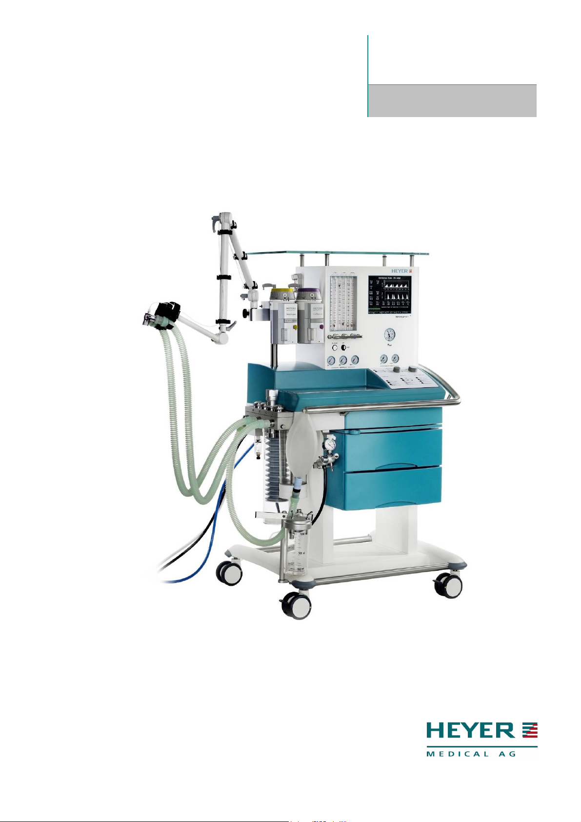
N a r k o m a t
+
A n e s t h e s i a S y s t e m
Operator’s Manual
Rev. 3.1 – 05/09
M
OD ER N SOL UT IO NS F OR ANE ST HE TI CS A ND INH AL AT IO N
Page 2

Page 3

H E Y E R N a r k o m a t+
Table of Contents
Page
Table of Contents ................................................................................................................................3
Table of Figures...................................................................................................................................6
1 Details of the Manufacturer / Apparatus.......................................................................................8
2 Description and Utilization of the Apparatus................................................................................9
2.1 General.....................................................................................................................................9
2.1.1 Product improvements.................................................................................................10
2.1.2 Responsibilities of operators........................................................................................11
2.1.3 Liability of the manufacturer.........................................................................................11
2.2 General precautions ...............................................................................................................12
2.2.1 Warning notes..............................................................................................................12
2.2.2 Caution notes...............................................................................................................13
3 Functional Description................................................................................................................14
3.1 Anesthesia ventilator ..............................................................................................................14
3.1.1 Fresh gas decoupling ..................................................................................................14
3.1.2 Constant volume provided by controlled ventilation....................................................14
3.1.3 Compliance compensation ..........................................................................................15
3.1.4 Bag-in-bottle system....................................................................................................15
3.2 Fresh gas dosing ....................................................................................................................15
3.3 Vaporizer mounting device and Vaporizers............................................................................16
3.4 Patient module........................................................................................................................17
3.4.1 Circuit absorber system...............................................................................................17
3.4.2 CO2 absorber...............................................................................................................17
3.4.3 Reservoir and manual ventilation bag .........................................................................17
3.4.4 Volume measurement..................................................................................................17
3.4.5 Oxygen measurement*................................................................................................17
3.4.6 Patient module heating................................................................................................18
3.5 Gas measurement*.................................................................................................................18
4 Operating Elements / Connections for Appliances ....................................................................19
4.1 Views of apparatus .................................................................................................................19
4.1.1 Front of apparatus........................................................................................................19
4.1.2 Rear of apparatus........................................................................................................20
4.1.3 Left side of apparatus ..................................................................................................21
4.1.4 Right side of apparatus................................................................................................22
4.2 Ventilator unit..........................................................................................................................23
4.2.1 Operating panel, ventilator keyboard...........................................................................24
4.2.1.1
"Ventilation Modes"- selection switch .................................................................24
4.2.1.2
"Push to Enter" - encoder button to change and confirm settings ......................25
4.2.1.3
Operating panel keys for insp. pause and exp. pause........................................25
4.2.1.4
"Settings" - panel keys for basic set-up ..............................................................25
4.2.1.5
"Alarms" - panel keys and displays for alarms....................................................26
4.2.1.6
Vent. Settings" - panel keys for direct selection display windows ......................26
4.3 Flow meter tube block including fresh gas dosing..................................................................27
4.4 Vaporizer mounting device .....................................................................................................28
4.5 Patient module (circuit system) ..............................................................................................29
4.6 Sample gas recirculation ........................................................................................................30
4.7 Vacuum source for bronchial suction (optional) .....................................................................31
4.8 Symbols on the Unit................................................................................................................32
5 Alarm Messages and Safety Devices ........................................................................................33
5.1 Alarm messages direct after the System start........................................................................34
5.2 Alarm Messages in Standby...................................................................................................35
5.3 Compliance test alarm messages ..........................................................................................36
5.3.1 Compliance test alarm messages................................................................................36
5.4 System test alarm messages .................................................................................................38
5.5 Alarm messages during normal operation..............................................................................40
5.5.1 Alarm messages during normal operation with the integrated Gas Module * .............45
5.5.2 Alarm messages during normal operation with the optional ventilation mode PCV....47
Rev. 3.1 – 05/09 HEYER Narkomat+, Operator’s manual 3 / 150
Page 4

H E Y E R N a r k o m a t+
5.6 Technical failure alarm message............................................................................................48
6 Start-Up and Functional Test.....................................................................................................48
6.1 Preparation of apparatus ........................................................................................................48
6.2 Pre-Operation Tests ...............................................................................................................49
6.3 Sample Tube Connection (optional integrated Gas Module) .................................................50
6.4 System Start ...........................................................................................................................51
6.5 Battery Control........................................................................................................................52
6.6 Sensor Test ............................................................................................................................52
6.6.1 Compliance Test..........................................................................................................54
6.7 System Test............................................................................................................................56
6.7.1 O2 sensor calibration* .................................................................................................58
6.7.2 Leak Test Fresh Gas Delivery System........................................................................62
6.8 Gas module verification*.........................................................................................................64
7 Operation in the Individual Functions.........................................................................................71
7.1 Standby mode.........................................................................................................................72
7.1.1 Standby mode menu window.......................................................................................73
7.1.2 Standby mode graphics window..................................................................................77
7.1.3 Standby mode options window....................................................................................78
7.1.4 Standby mode screen saver function..........................................................................79
7.2 Control Panel Keys in the Ventilation Modes CMV / (S)CMV / PCV * Adult / Child...............80
7.2.1 Menu-Window in the Ventilation Modes CMV / (S)CMV / PCV * Adult / Child............80
7.2.2 Graphic Window in the Ventilation Modes CMV / (S)CMV / PCV * Adult / Child ........81
7.2.3 Options Window in the Ventilation Modes CMV / (S)CMV / PCV * Adult / Child.........82
7.2.4 Automatic Anesthetic Agent and Agent Mixture Identification * ..................................83
7.2.5 Panel Key VT/V in the Ventilation Modes CMV / (S)CMV Adult / Child ......................85
7.2.6 Panel Key VT/V in the Ventilation Mode PCV Adult / Child.........................................86
7.2.7 Panel Key f in the Ventilation Modes CMV / (S)CMV / PCV Adult / Child...................87
7.2.8 Panel Key I:E in the Ventilation Modes CMV / (S)CMV / PCV Adult / Child................88
7.2.9 Panel Key PEEP in the Ventilation Modes CMV / (S)CMV / PCV Adult / Child ..........89
7.3 “Manual/spontaneous” ventilation mode.................................................................................90
7.3.1 “Manual/spontaneous” ventilation mode......................................................................90
7.3.1.1
Alarm limit setting in “manual/spontaneous” mode.............................................94
7.4 Controlled Ventilation Mode....................................................................................................98
7.4.1 CMV adult ventilation mode.........................................................................................99
7.4.1.1
Parameter Settings in CMV Adult Mode...........................................................104
7.4.1.2
Alarm limits setting in CMV adult mode............................................................105
7.4.1.3
Alarm limits setting in CMV child mode.............................................................108
7.5 Ventilation mode (S)CMV .....................................................................................................109
7.5.1 Ventilation mode (S)CMV ..........................................................................................110
7.5.1.1
Changing parameter settings in (S)CMV adult mode .......................................115
7.5.1.2
Alarm limits setting in (S)CMV adult mode .......................................................116
7.5.1.3
Alarm limits setting in (S)CMV child mode........................................................119
7.6 Ventilation mode PCV...........................................................................................................120
7.6.1 PCV adult ventilation mode .......................................................................................121
7.6.1.1
Changing graphic settings in PCV Adult mode.................................................126
7.6.1.2
Alarm limits setting in PCV adult mode.............................................................127
7.6.1.3
Alarm limits setting in PCV child mode.............................................................130
8 Dismantling and Reassembling................................................................................................131
8.1 Patient module......................................................................................................................131
8.1.1 CO2 absorber canister ...............................................................................................131
8.1.2 Bag-in-bottle system..................................................................................................131
8.1.3 Replacing the expiratory flow sensor.........................................................................133
8.1.4 Dismantling the ventilation pressure valve (APL)......................................................133
8.1.5 Replacing the diaphragm valves................................................................................135
8.1.6 Valves (emergency air, inspiration, and expiration valve).........................................137
8.2 Connecting and disconnecting of the vaporizers..................................................................137
9 Cleaning ...................................................................................................................................138
9.1 Cleaning and sterilizing the apparatus .................................................................................138
9.1.1 Cleaning the housing.................................................................................................138
9.2 Patient module......................................................................................................................138
9.2.1 Sterilizing the patient module.....................................................................................138
4 / 150 HEYER Narkomat+, Operator’s manual Rev. 3.1 - 05/09
Page 5

H E Y E R N a r k o m a t+
10 Preventive Maintenance and Servicing................................................................................139
10.1
General...........................................................................................................................139
10.1.1 Preventive Maintenance by a qualified technician.....................................................139
10.1.1.1 6 Month Service Interval ...................................................................................139
10.1.1.2 12 Month Service Interval .................................................................................140
10.1.1.3 36 Month Service Interval .................................................................................141
10.2
Servicing the Vaporizer..................................................................................................141
10.3
Other Servicing...............................................................................................................141
11 Specifications........................................................................................................................142
12 Warranty ...............................................................................................................................146
Rev. 3.1 – 05/09 HEYER Narkomat+, Operator’s manual 5 / 150
Page 6

H E Y E R N a r k o m a t+
V
Table of Figures
Fig. 1 Front view of the apparatus......................................................................................................................... 19
Fig. 2 Rear of the apparatus.................................................................................................................................. 20
Fig. 3 Left side view on the apparatus................................................................................................................... 21
Fig. 4 Right side view on the apparatus................................................................................................................. 22
Fig. 5 Ventilator display and airway pressure gauge ............................................................................................. 23
Fig. 6 Operating panel, ventilator keyboard........................................................................................................... 24
Fig. 7 Flow meter block including fresh gas dosing............................................................................................... 27
Fig. 8 Vaporizer mounting device.......................................................................................................................... 28
Fig. 9 Patient module (circuit system).................................................................................................................... 29
Fig. 10 Sample gas recirculation and .................................................................................................................... 30
Fig. 11 Vacuum source.......................................................................................................................................... 31
Fig. 12 Example of an alarm message during the booting procedure.................................................................... 34
Fig. 13 Example of an alarm message during the booting procedure.................................................................... 35
Fig. 14 Example of a sensor test alarm message.................................................................................................. 36
Fig. 15 Example of a system test alarm message................................................................................................. 38
Fig. 16 Example of an alarm message during normal operation............................................................................ 40
Fig. 17 “Major Technical Failure” alarm message.................................................................................................. 48
Fig. 18 First display message during system start................................................................................................. 51
Fig. 19 Second display message during system start............................................................................................ 51
Fig. 20 Display before sensor test......................................................................................................................... 52
Fig. 21 Display after the sensor test....................................................................................................................... 53
Fig. 22 Display prior to the compliance test........................................................................................................... 54
Fig. 23 Display after the compliance test as extended information........................................................................ 55
Fig. 24 Display after the compliance test as pass/fail information ......................................................................... 55
Fig. 25 System test selection display..................................................................................................................... 56
Fig. 26 Display of system test selection sub-menu................................................................................................ 57
Fig. 27 First display message of O2 sensor calibration.......................................................................................... 58
Fig. 28 Second display message of O2 sensor calibration..................................................................................... 59
Fig. 29 Third display message of O2 sensor calibration......................................................................................... 60
Fig. 30 Fourth display message of O2 sensor calibration....................................................................................... 61
Fig. 31 Display prior to the fresh gas system leak test .......................................................................................... 62
Fig. 32 Display after the Leak Test Fresh Gas Delivery System............................................................................ 63
Fig. 33 Display of the gas module verification ....................................................................................................... 64
Fig. 34 Connection of the tube system to the verification gas bottle...................................................................... 65
Fig. 35 Display No. 1 for gas measurement verification ........................................................................................ 65
Fig. 36 Display No. 2 for gas measurement verification ........................................................................................ 66
Fig. 37 Display No. 3 for gas measurement verification ........................................................................................ 67
Fig. 38 Display No. 4 for gas measurement verification ........................................................................................ 68
Fig. 39 Display No. 5 for gas measurement verification ........................................................................................ 69
Fig. 40 Display No. 6 for gas measurement verification ........................................................................................ 70
Fig. 41 Control panel ............................................................................................................................................. 71
Fig. 42 Standby mode display ............................................................................................................................... 72
Fig. 43 Standby mode menu window..................................................................................................................... 73
Fig. 44 "Set time" within the menu window............................................................................................................ 74
Fig. 45 "Load/save personal alarm limits" within the menu window....................................................................... 75
Fig. 46 "System test options“ within the menu window.......................................................................................... 76
Fig. 47 Standby mode graphic settings window..................................................................................................... 77
Fig. 48 Stand-by mode options display.................................................................................................................. 78
Fig. 49 Screen saver ............................................................................................................................................. 79
Fig. 50 Menu-Window in the ventilation mode CMV-Adult..................................................................................... 80
Fig. 51 Graphic-Window in the ventilation mode CMV-Adult................................................................................. 81
Fig. 52 Options-Window in the ventilation mode CMV-Adult ................................................................................. 82
Fig. 53 Vt adjustment in the ventilation mode CMV Adult...................................................................................... 85
Fig. 54
Fig. 55 Rate adjustment in the ventilation mode CMV Adult.................................................................................. 87
Fig. 56 I:E adjustment in the ventilation mode CMV Adult..................................................................................... 88
Fig. 57 PEEP adjustment in the ventilation mode CMV Adult................................................................................ 89
Fig. 58 "Manual/spontaneous settings" display 1 .................................................................................................. 90
Fig. 59 "Manual/spontaneous settings" display 2 .................................................................................................. 91
Fig. 60 "Manual/spontaneous settings" display 3 .................................................................................................. 92
Fig. 61 Ventilation pressure valve (APL) in CMV/SP setting.................................................................................. 93
Fig. 62 Ventilation pressure valve (APL) in 20 cmH2O setting.............................................................................. 93
Fig. 63 Alarm limits 1 in the Manual/spontaneous ventilation mode...................................................................... 94
Fig. 64 Display “Alarm limits 2 in the Manual/spontaneous ventilation mode”....................................................... 95
Fig. 65 Alarm limits in manual/spontaneous mode................................................................................................ 96
&
adjustment in the ventilation mode PCV Adult....................................................................................... 86
6 / 150 HEYER Narkomat+, Operator’s manual Rev. 3.1 - 05/09
Page 7

H E Y E R N a r k o m a t+
Fig. 66 Graphics window in manual/spontaneous ventilation mode ...................................................................... 97
Fig. 67 Display “ventilation mode adult”................................................................................................................. 99
Fig. 68 "CMV-Settings / Adult" display................................................................................................................. 100
Fig. 69"Start in CMV adult" ventilation mode display........................................................................................... 102
Fig. 70" CMV adult" ventilation mode display...................................................................................................... 103
Fig. 71 "Parameter setting during the CMV adult" ventilation mode display........................................................ 104
Fig. 72 Display “Alarm limits 1 in the CMV Adult ventilation mode ...................................................................... 105
Fig. 73 Display “Alarm limits 2 in the CMV Adult ventilation mode” ..................................................................... 106
Fig. 74 Alarm limits in the CMV Adult ventilation mode ....................................................................................... 107
Fig. 75 Alarm limits in the CMV Child ventilation mode ....................................................................................... 108
Fig. 76 Display “ventilation mode adult”............................................................................................................... 110
Fig. 77 "(S)CMV-Settings / Adult" display............................................................................................................ 111
Fig. 78 "(S)CMV adult" ventilation mode display 1 .............................................................................................. 113
Fig. 79 "(S)CMV adult" ventilation mode display 2 .............................................................................................. 114
Fig. 80"Parameter setting during the (S)CMV adult" ventilation mode display .................................................... 115
Fig. 81 "Alarm Settings" ventilation mode (S)CMV adult ..................................................................................... 116
Fig. 82 Display “Alarm limits 2 in the (S)CMV Adult ventilation mode” ................................................................ 117
Fig. 83 Alarm limits in the (S)CMV Child ventilation mode................................................................................... 118
Fig. 84 Alarm limits in the (S)CMV Child ventilation mode................................................................................... 119
Fig. 85 Display “ventilation mode adult”............................................................................................................... 121
Fig. 86 "PCV -Settings / Adult" display ................................................................................................................ 122
Fig. 87 "Start in PCV adult" ventilation mode display .......................................................................................... 124
Fig. 88 "PCV adult" ventilation mode display....................................................................................................... 125
Fig. 89 "Parameter setting during the PCV adult" ventilation mode display......................................................... 126
Fig. 90 Display “Alarm limits 1 in the PCV adult ventilation mode”...................................................................... 127
Fig. 91 Display “Alarm limits 2 in the PCV adult ventilation mode”...................................................................... 128
Fig. 92 Alarm limits in the PCV adult ventilation mode ........................................................................................ 129
Fig. 93 Alarm limits in the PCV Child ventilation mode........................................................................................ 130
Fig. 94 Dismantling of the patient module, front view .......................................................................................... 132
Fig. 95 Dismantling of the patient module, top view ............................................................................................ 134
Fig. 96 Dismantling of the valve bodies............................................................................................................... 136
Rev. 3.1 – 05/09 HEYER Narkomat+, Operator’s manual 7 / 150
Page 8
H E Y E R N a r k o m a t+
1 Details of the Manufacturer / Apparatus
Apparatus: Anesthesia system HEYER NARKOMAT
Manufacturer: HEYER Medical AG
Carl-Heyer-Strasse 1-3
56130 Bad Ems
Germany
Tel: ++49 2603 / 791-3
Fax: ++49 2603 / 70424
E-Mail: info@heyermedical.de
Software version: Display driver software: 3.0
Ventilator software: 2.5.n
+
Certificate-No.: 04 207-1743/98
8 / 150 HEYER Narkomat+, Operator’s manual Rev. 3.1 - 05/09
Page 9

H E Y E R N a r k o m a t+
2 Description and Utilization of the Apparatus
2.1 General
Introduction
The HEYER NARKOMAT+ anesthesia system represents a flexible anesthesia workplace for
implementing and monitoring inhalation anesthesia in the half-closed system and the nearly
closed system for low-flow techniques with minimum gas- and anesthetic agent utilization.
During the development of the system special emphasis was placed on the ergonomic design
and consequently, a secure and easy operation. Furthermore the excellent air-tightness of the
system ensures the economical daily high and low pressure utilization.
The standard model contains the following system components:
A. Electronic ventilator
The process-controlled ventilator allows constant-volume ventilation for all patient groups with
a body weight of 3 kg upwards. Due to the system compliance compensation, even small tidal
volumes can be precisely administered. The ventilation type CMV as the standard, the
(S)CMV and PCV as optional ventilation modes, as well as various forms of ventilation and
considerable variation options of the artificial ventilation cycle, facilitate a secure ventilation
even for complicated lung conditions. A comprehensive test and alarm management ensures
the required safety for patients and prevents out-of-control operating conditions. The clear
design of the user interface and the display allow the secure operation and a quick detection
of the selected ventilation parameters.
B. The patient module
The circular patient absorber system is highly integrated and compacted in an aluminum
block. The block is tempered to prevent the formation of condensation. The block also
contains an emergency air valve, a fresh gas reservoir in form of a hand-held anesthesia bag
and an expiratory flow sensor. A motor drive connects the module to the basic apparatus. All
sensors are continuously monitored during operation. The sensors are automatically
calibrated during the start-up of the apparatus.
C. Integrated fresh-gas dosing system including vaporizer unit
The flow meter tube block contains all mandatory safety equipment as well as a pneumatic
control system to maintain a minimum oxygen concentration of 25% in the fresh-gas flow
(ratio system).
Rev. 3.1 – 05/09 HEYER Narkomat+, Operator’s manual 9 / 150
Page 10

H E Y E R N a r k o m a t+
D. Integrated gas measurement
CO2
The continuous CO2 measurement is graphically shown as a capnogramm. The end
expiratory and inspiratory CO2 measurement will be shown as a numerical value. The CO2
values can be displayed in Vol% or mmHg.
N2O
The nitrous oxide measurement is similar to the CO2 measurement and will be shown in Vol%
in the form of numerical values.
O2
The display of the oxygen measurement is based on the same principles as the measurement
of CO2 and N2O and will be shown in Vol% in the form of numerical values.
Anesthesia gas
The gas module is equipped with an automatic anesthetic agent and anesthetic agent mixture
identification. The apparatus measures the agents Halothane, Isoflurane, Enflurane,
Desflurane and Sevoflurane. The display of the Anesthesia gas measurement is based on the
same principles as the measurement of CO2, N2O and O2 .
MAC
The displayed Minimal Alveolar Concentration is calculated according to the following
formula:
EtAA[%] EtN20[%]
MAC (AA) = ------------ + ------------ xAA 100
AA = Anesthetic agent
Et = End expiratory concentration
x = Alveolar concentration of the Anesthetic agent for MAC =1 at 100% O2 and
patient age of 40 years.
2.1.1 Product improvements
HEYER MEDICAL AG retains the right to carry out modifications or to update the apparatus
and/or operating instructions without prior notification. These Operating Instructions explain all
features of the HEYER NARKOMAT+ anesthesia system and are correct at going to print.
Instructions and models produced at a later stage may already contain improvements or
modifications that were not included in previous models.
10 / 150 HEYER Narkomat+, Operator’s manual Rev. 3.1 - 05/09
Page 11

H E Y E R N a r k o m a t+
2.1.2 Responsibilities of operators
The correct functioning of the HEYER NARKOMAT+ anesthesia system can only be
guaranteed if the apparatus is operated and serviced in accordance with the information
provided by the manufacturer. The non-compliance with this information voids all guarantee
claims against HEYER MEDICAL AG.
NOTE: Before using the apparatus please study the Operating Instructions as well as the
section "General precautions", observing all information contained in these Operating
Instructions that are highlighted with CAUTION or WARNING. These Operating Instructions
only describe the operation of the apparatus. Information about service and repair by qualified
trained personnel are contained in the HEYER NARKOMAT+ SERVICE INSTRUCTIONS.
The apparatus may only be operated by qualified and trained skilled personnel. All operators
must fully observe these Operating Instructions or relevant additional documentation and
information provided by the manufacturer. They must also comply with the general
precautions detailed below and must be trained by authorized medical product consultants.
The apparatus may only be operated with an additional gas monitoring if a gas monitoring is
not included. The following conditions must be fulfilled (DIN 13 252):
At least the:
- anesthesia-gas concentration and
- the carbon dioxide concentration
must be monitored.
Upper and lower alarm limits must be set for these monitoring parameters. Upon reaching
one of these upper or lower alarm limits, an optical and acoustic alarm must be triggered.
The measuring adapter to be installed in the circular system or patient hose system must
contain ISO cones (DIN 13 252). These must be applied to the inspiration hose connection or
ideally to the Y piece. Measuring close to the tube is, however, recommended as this allows
the recording of the inspiratory and expiratory gas values. Monitors using the side-stream
procedure should be clearly preferred as a supplement to the additionally required gas
monitoring.
Any apparatus not functioning as described in these Operating Instructions must not be used
until the fault has been removed. The operators are responsible for any damage or injuries
caused by the incorrect operation or repair/servicing of the apparatus by unauthorized
personnel.
2.1.3 Liability of the manufacturer
HEYER MEDICAL AG shall only be liable for the safety, reliability and functionality of the
apparatus, if:
- the apparatus was operated in accordance with the information issued by the manufacturer;
- extensions, new adjustments, modifications or repairs have been carried out by an expert
authorized by the manufacturer;
- the apparatus was only operated in buildings containing grounding facilities according to the
IEC regulations.
Rev. 3.1 – 05/09 HEYER Narkomat+, Operator’s manual 11 / 150
Page 12

H E Y E R N a r k o m a t+
2.2 General precautions
2.2.1 Warning notes
NOTE: A warning note points out potentially dangerous situations which may cause injuries to
the patient or operating personnel.
Carry out the daily checks specified on the checklist and do not operate the system in case of
a fault until the fault has been repaired.
If possible, always connect the output of the ventilation pressure valve (APL) to the anesthetic
gas removal line, usually installed in the operating theatre.
The patient should furthermore be visually monitored by qualified personnel. In certain
situations, life-threatening circumstances may occur which may not necessarily trigger an
alarm.
Always set the alarm limits so that the alarm is triggered before hazardous situations occur.
Incorrectly set alarm limits may result in operating personnel not being aware of drastic
changes in the patient’s condition.
Always check that the displayed ventilation pressure value lies within an acceptable range
before activating the "Set Pmin/Pmax automatically" function, automatically setting new alarm
limits.
In order to prevent an electric shock, the apparatus (protection class I) may only be
connected to a correctly grounded mains connection (socket outlet with grounding contact).
Explosion hazard! The apparatus may not be operated near flammable anesthetic agents or
other flammable substances. No flammable anesthetic agents (i.e. ether, cyclopropane) may
be used.
As the apparatus may not be used with inflammable anesthetic agents (i.e. ether,
cyclopropane), no antistatic ventilation hoses or face masks are required (DIN VDE750, part
214).
Electric shock and fire hazard! Always switch off the apparatus and disconnect from mains
before cleaning.
Fire hazard! Fuses (i.e. additional sockets) may only be replaced by fuses of the same type
and with the same fuse value.
Electric shock hazard! The apparatus may only be opened by qualified or authorized experts.
The connection of apparatus via the additional socket may, in case of a failure of the
protective conductor, lead to a discharge current exceeding the permissible values.
Electromagnetic radiation disturbances exceeding the values of EN 60601-1-2, can affect the
function of the machine.
12 / 150 HEYER Narkomat+, Operator’s manual Rev. 3.1 - 05/09
Page 13

H E Y E R N a r k o m a t+
2.2.2 Caution notes
NOTE: A CAUTION note refers to a situation which may cause damage or the incorrect
function of the apparatus.
This apparatus may only be operated by trained, skilled medical staff.
Before starting the apparatus, the operating personnel must be familiar with the notes and
information contained in these Operating Instructions and must have been trained by a
medical product consultant.
If the apparatus does not function as described, the apparatus must be examined and
possibly repaired by qualified service personnel, before being used again.
Handle the apparatus with care to prevent damage or functional faults.
Ensure that the gas supply of the apparatus always complies with the technical specification.
Before the operation, the apparatus must be correctly calibrated and/or the respective
apparatus tests, as described in the Operating Instructions, must be carried out.
If the apparatus should show faults during the initial calibration or testing, the apparatus may
not be operated until the fault has been repaired by a qualified expert.
After servicing, a functional test and a sensor and system test must be carried out before
clinical use.
Only bacteriological filters with a low flow resistance must be connected to the patient module
and/or the patient connection.
* After the unit has been switched on, a warming period of 4 minutes is necessary to ensure
an exact measurement of the anesthesia gas values. The other breathing gas values are
within the ISO specifications after 1 min
* Only use the recommended pressure controller when doing the gas verification. A to high or
to low calibration gas flow can lead to faulty result.
* Use only the original tube system as measuring tube.
* The gas measurement tube system at the monitor must be connected before putting the
apparatus into use or changing the flow rate. Otherwise the apparatus might falsely detect a
tube blockage.
Rev. 3.1 – 05/09 HEYER Narkomat+, Operator’s manual 13 / 150
Page 14

H E Y E R N a r k o m a t+
3 Functional Description
3.1 Anesthesia ventilator
Ventilators are described according to the principle of controlling the change over from
inspiration to expiration. The NARKOMAT+ apparatus offers the following characteristics in
the controlled ventilation mode or so-called CMV mode (Controlled Mandatory Ventilation).
time-controlled:
The timely sequence of inspiration and expiration has been specified by the ventilation
frequency settings. The ratio of the inspiration to the expiration time of the individual
ventilation cycle is determined by the adjustable I/E ratio.
pressure limitation:
The tidal volume during controlled ventilation is supplied during the entire period of the
inspiratory flow and can be set as ventilation parameter. The inspiration is, however,
terminated before the tidal volume has been administered, once the measured airway
pressure reaches the set Peak pressure alarm limit.
constant volume:
The inspiratory flow to the patient required for ventilation with the set parameters, frequency f,
tidal volume T. Vol. and ventilation time ratio I/E, is automatically calculated by the ventilator.
This inspiratory flow is generated via the drive gas for the patient module. In standard
anesthesia ventilators, deviations to the tidal volume actually supplied to the patient could
occur due to the respective fresh gas setting and system compliance of the ventilation
system. The ventilator of the NARKOMAT+ apparatus supplies in each setting a constant
volume. The patient module containing the bellows is decoupled from the fresh gas, and the
system compliance of the patient module is automatically taken into consideration by the
ventilator when generating the tidal volume.
3.1.1 Fresh gas decoupling
During the fresh gas decoupling in the CMV mode, the fresh gas flow is directed into the
manual ventilation bag. The manual ventilation bag serves as a fresh gas reservoir. This
principle offers the following advantages for controlled ventilation:
1. The tidal volume is completely independent from the set fresh gas flow. The
ventilation is therefore also referred to as constant volume ventilation.
2. The fresh gas flow can be maintained at a very low level, i.e. below 500 ml/min,
depending on the patient. The manual ventilation bag serves as a reservoir for the
fresh gas administered during the inspiration. The entire fresh gas volume is available
during the next inspiration, i.e. not only the fresh gas stored in the reservoir but also
the fresh gas supplied during the expiration period.
3.1.2 Constant volume provided by controlled ventilation
During controlled CMV ventilation, the set tidal volume is administered irrespective of the
pulmonary circumstances. The ventilator drive represents, in principle, a constant flow
generator. The inspiratory flow of the ventilation gas is automatically adapted to the
respective settings of the tidal volume VT, the ventilation frequency RATE and the ventilation
time ratio I/E.
14 / 150 HEYER Narkomat+, Operator’s manual Rev. 3.1 - 05/09
Page 15

H E Y E R N a r k o m a t+
3.1.3 Compliance compensation
The administered tidal volume is corrected to the set value, set by the user, with the aid of the
compliance compensation. The system compliance of each ventilation system, i.e. the
compliance of patient hoses and the patient module, always leads to losses in the
administered tidal volume. The NARKOMAT+´s automatic compensation of the system
compliance can correct this volume loss with the aid of a control loop. For this purpose
several ventilation cycles are required with the drive gas flow being slightly increased above
the normal values, i.e. the values for achieving the set ventilation volume. The correct tidal
volume is, however, administered to the patient, whilst the slightly higher volume is absorbed
by the system compliance due to the effective compliance compensation.
3.1.4 Bag-in-bottle system
The so-called bag-In-bottle system is part of the patient section or circuit system. The gasconducting sections are divided from the ventilator into a primary (ventilator) and a secondary
circuit (patient). The gas volume provided by the drive is not directly administered to the
patient but instead compresses a bellows inside a pressure dome. As a result, the ventilation
gas contained in the bellows is administered to the patient. An increased drive volume,
flowing into the pressure dome, also increases the tidal volume. Once the drive-gas flow has
finished, also the pressure compensation between the primary and secondary circuit is
ended. A distinctive plateau in the ventilation pressure curve is formed, if the system does not
switch over to the expiration directly after the end of the inspiratory gas flow. For this purpose,
the drive volume contained in the pressure dome is maintained at a steady level for some
time. The Bellow is suitable for adults and children. An exchange of the bellows for different
patient groups is not necessary.
3.2 Fresh gas dosing
The set-up of the gas quantities administered to the patient is carried out on a measuring tube
block. This block contains measuring tubes that are also referred to as rotameters. These
measuring tubes consist of a vertical glass tube, containing a suspended body. As the glass
tubes expand towards the top, a certain gas flow lifts the suspended body to a respective
height. The gas flow is adjusted via valve spindles, located below the individual measuring
tube.
The setting of the O2/AIR or O2/N2O is selected with the change-over switch which opens the
respective gas line to the measuring tube block.
The fresh gas cannot be set with a mixture of AIR and N2O as, in this case, a decrease of the
oxygen content to below 21% could not be avoided.
The decrease of the oxygen content to below 21% is in theory also possible with O2 and N2O
gas dosing. Such unfavorable settings are, however, prevented by a pneumatic safety
system. This system, which is also referred to as RATIO system ensures the continuous
existence of a minimum O2 content of 25% in the dosed gas mixed with N2O. In case of an
increase of the N2O flow, the required O2 flow is also automatically increased. The thus set
fresh gas is then fed over a vaporizer, where it is mixed with anesthetic agent.
Rev. 3.1 – 05/09 HEYER Narkomat+, Operator’s manual 15 / 150
Page 16

H E Y E R N a r k o m a t+
3.3 Vaporizer mounting device and Vaporizers
The apparatus contains a Selectatec compatible vaporizer
accommodating two vaporizers. The vaporizer contains two chambers, with the bottom
section containing the liquid anesthetic agent. Via a woven metal wick, the top section of the
chamber is enriched with saturated anesthetic agent steam. The concentration of the
saturated steam at ambient temperatures is considerably higher than that acceptable for
clinical purposes. The desired concentration is achieved by a suitable mixing ratio of the gas
and anesthetic agent with a gas flow that is passed around this chamber. This is achieved
with the aid of the setting wheel. For this purpose, the ratio of the flows of the carrier gas is
adjusted by a bypass channel and the vaporizer channel in such a way, that the chosen
concentration is achieved at the vaporizer outlet. In the zero position of the vaporizer, this
bypass channel remains open whilst the vaporizer chamber is completely closed for the gas
flow.
Although the anesthetic agent steam concentration of the vaporizer chamber is saturated, the
absolute anesthetic agent content depends, however, on the temperature. Consequently, the
bypass channel contains a temperature compensation valve which in case of changes in the
steam pressure caused by temperature fluctuations, changes the set dilution ratio in such a
way that the anesthetic agent concentration issued is no longer dependant on the
temperature.
For further information see:
Instructions of the respective anesthetic agent vaporizer.
mounting device
16 / 150 HEYER Narkomat+, Operator’s manual Rev. 3.1 - 05/09
Page 17

H E Y E R N a r k o m a t+
3.4 Patient module
3.4.1 Circuit absorber system
The circuit absorber system consists of a ventilation system with CO2 absorber. This system
allows anesthetics to be carried out at extreme low fresh gas settings. The ventilation gas
contains various parts of re-breathing gas, i.e. expiratory gas freed from CO2 parts. This is
achieved with a circuit ventilation system, facilitating a re-breathing of the expiratory CO2containing gas. A circuit system with high re-breathing contents causes a reduction of the
consumption of anesthetic agents. This system also offers an improved breathing gas
conditioning. The patient module is designed as a circuit absorber system in the form of a
compact aluminum block. The hose connections normally required between the ventilator and
the circuit system are thus no longer needed.
3.4.2 CO2 absorber
The absorber serves to absorb the soda lime and aims to remove the CO2 from the expiration
air. The absorption process is a chemical reaction in which carbon dioxide is bound, most of
the reaction water evaporates and the calcium is removed. Consequently the spent soda lime
is dry and hard. The soda lime must be stored hermetically sealed, cool and dry in order not
to become malabsorbant.
3.4.3 Reservoir and manual ventilation bag
The reservoir consisting of a manual ventilation bag provides an inspiratory interim store for
the fresh gas. The reservoir pressure during machine and spontaneous breathing is limited to
1-2 cmH2O. During manual breathing, this valve also allows the manual adjusting of the
desired ventilation pressure.
3.4.4 Volume measurement
Volume measurement is carried out by using a flow meter, operating according to the hot-wire
anemometer principle, to measure the flow in the expiration branch. The ventilator processors
integrate this measured value with the displayed tidal and ventilation minute volume. The tidal
volume shown in the display is a measured value. The tidal volume displayed during
controlled ventilation is measured by an internal flow sensor and is not dependent on the
expiratory volume measurement.
3.4.5 Oxygen measurement*
The oxygen is metered by a measuring cell installed on the inspiration valve. This singlecathode measuring cell, also referred to as fuel cell, offers a longer life compared to other
oxygen cells and is less sensitive to existing anesthetic gases.
*not valid with the apparatus option with integrated gas module
Rev. 3.1 – 05/09 HEYER Narkomat+, Operator’s manual 17 / 150
Page 18

H E Y E R N a r k o m a t+
3.4.6 Patient module heating
The heating prevents the formation of condensation in the patient module and on the valve
caps of the inspiration and expiration valve. The heating positively contributes to a ventilation
gas conditioning. The heating mat also functions as a sealing mat and is installed between
the top and bottom section of the patient module. An electronic control integrated in the
ventilator, keeps the temperature of the patient module constant at an approx. 36°C. An overtemperature protection protects the apparatus against overheating.
3.5 Gas measurement*
The measurement of the single gases in the breathing gas is based on the principle that
different gases absorb a different wavelength of infrared light. A pump inside the apparatus
continuously sucks a breathing gas probe out of the respiratory circulation into the
measurement chamber via a sampling line which is included with the gas module. This gas
probe flows through the measurement chamber where the absorption of the different wave
lengths of infrared light is measured. Based on these measurements, a microprocessor
calculates the concentration of CO2, N2O and anesthesia gas.
The measurement of oxygen is done with a paramagnetic oxygen sensor. This principle of
measurement is based on the paramagnetic characteristics of the oxygen molecule, through
which the oxygen concentration can be measured magnetically.
* only valid with the apparatus option with integrated gas module
18 / 150 HEYER Narkomat+, Operator’s manual Rev. 3.1 - 05/09
Page 19
H E Y E R N a r k o m a t+
4 Operating Elements / Connections for Appliances
4.1 Views of apparatus
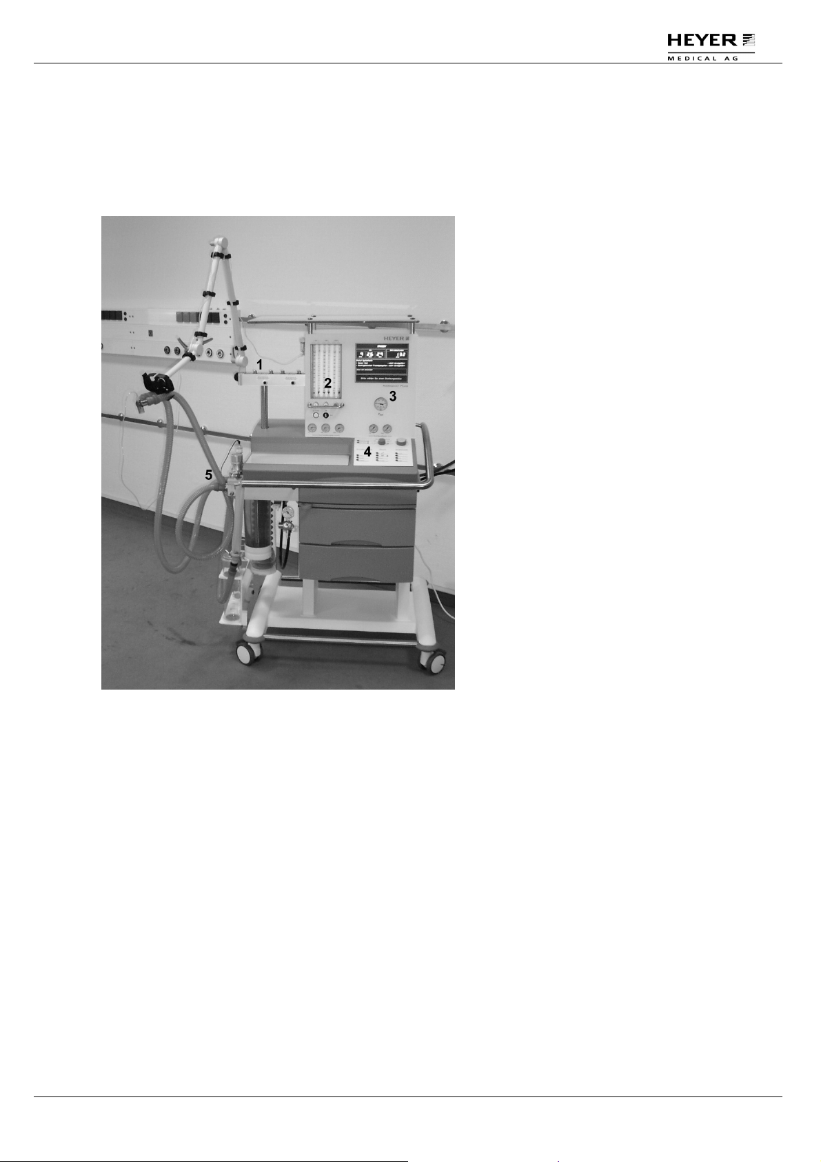
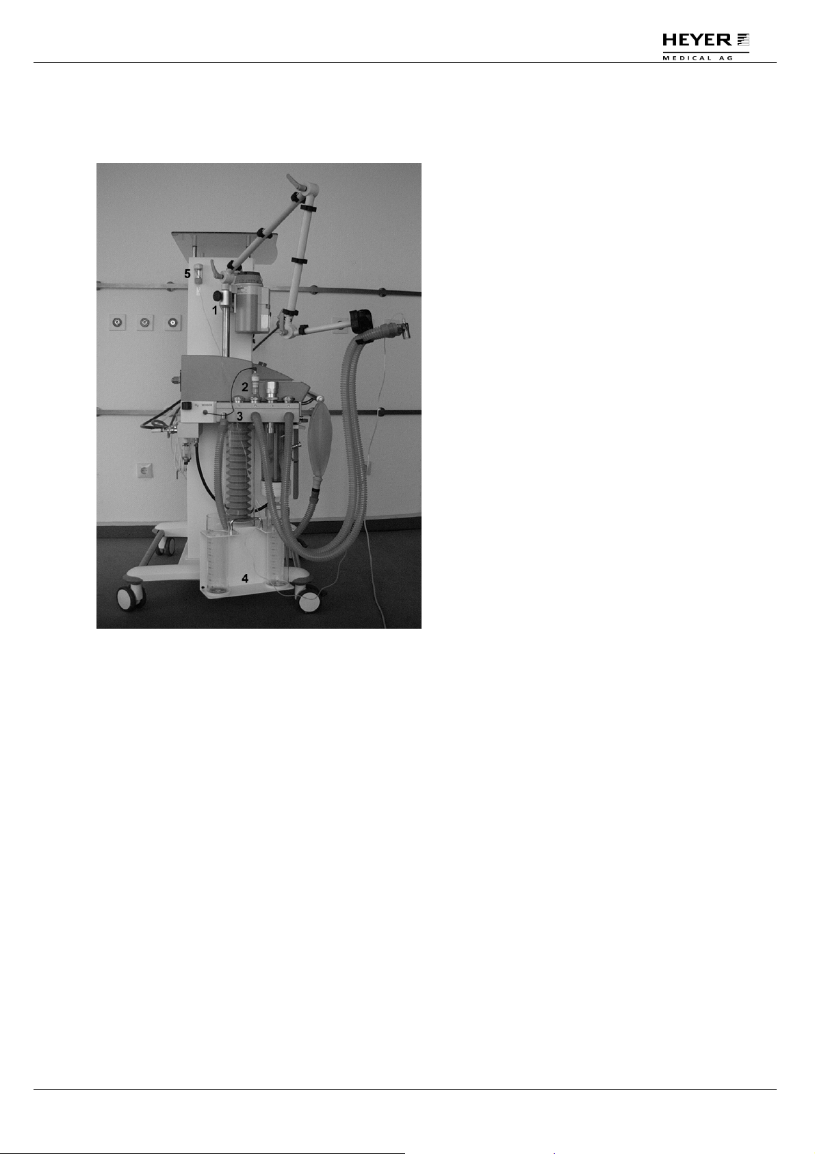
4.1.1 Front of apparatus
Fig. 1 Front view of the apparatus
1 Vaporizer mount
Selectatec* compatible
vap. mount for
connection of 2
vaporizers.
2 Flow meter block
6-fold flow meter block
with integrated Ratiosystem, O2-Bypass
and N20/AIR change
over switch.
3 Ventilator unit
Microprocessor
controlled ventilator
with TFT-display.
4 Control panel
Control panel with
keys, selector switch
and encoder (rotary
switch).
5 Patient module
Absorber circuit system
with integrated bag-inbottle system, active
and passive valves,
such as APL-valve.
Rev. 3.1 – 05/09 HEYER Narkomat+, Operator’s manual 19 / 150
Page 20
H E Y E R N a r k o m a t+
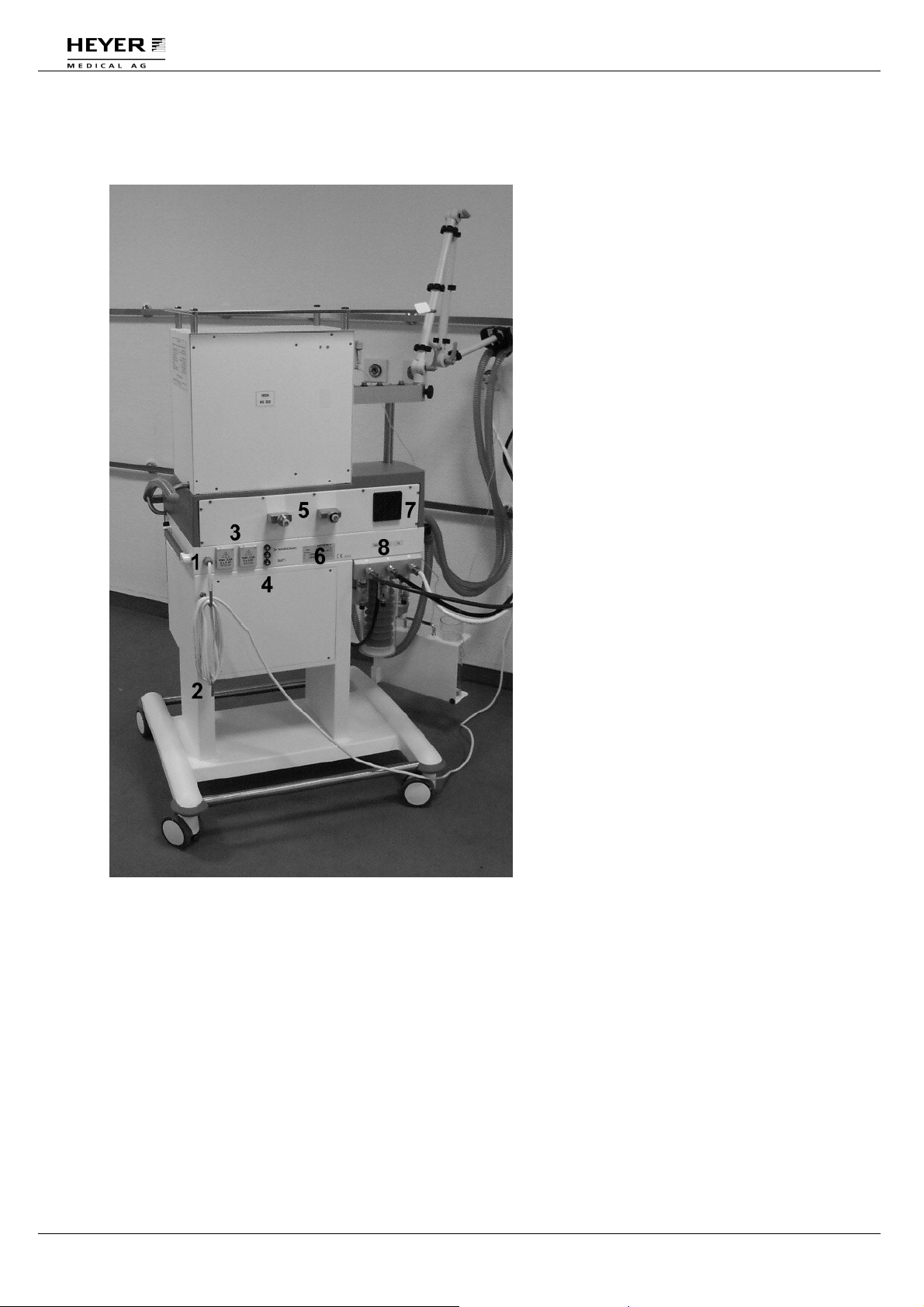
4.1.2 Rear of apparatus
Fig. 2 Rear of the apparatus
1 Mains cable
Voltage supply cable for
connecting the apparatus
to a socket with
grounding contact.
2 Cable hooks
3 Sockets
Additional devices
can be connected.
4 Circuit breakers
One 5A circuit breakers
for the ventilator unit ,
one 5A circuit breaker for
the battery and one 10A
(or two 5A) circuit breaker
for the convenient
receptacles
5 Cylinder jokes
Pin-index or DGAI
cylinder jokes, one for
N2O, one for O2.
6 Serial number
7 Fan
A fan provides ventilation
of the housing and
cooling of the integral
components.
8 Pipeline supply
connections
Connections for O2, AIR
and N2O from central gas
supply. Three pipeline
pressure gauges inform
about supply pressure.
20 / 150 HEYER Narkomat+, Operator’s manual Rev. 3.1 - 05/09
Page 21
H E Y E R N a r k o m a t+
4.1.3 Left side of apparatus
Fig. 3 Left side view on the apparatus
1 Holder for patient arm
2 Oxygen-sensor with
cable*
3 Patient module
4 Suction stand with
glasses (option)
5 Water trap with gas
measurement inlet**
* Only valid without the
option gas module
**Only valid with the
option gas module
Rev. 3.1 – 05/09 HEYER Narkomat+, Operator’s manual 21 / 150
Page 22
H E Y E R N a r k o m a t+
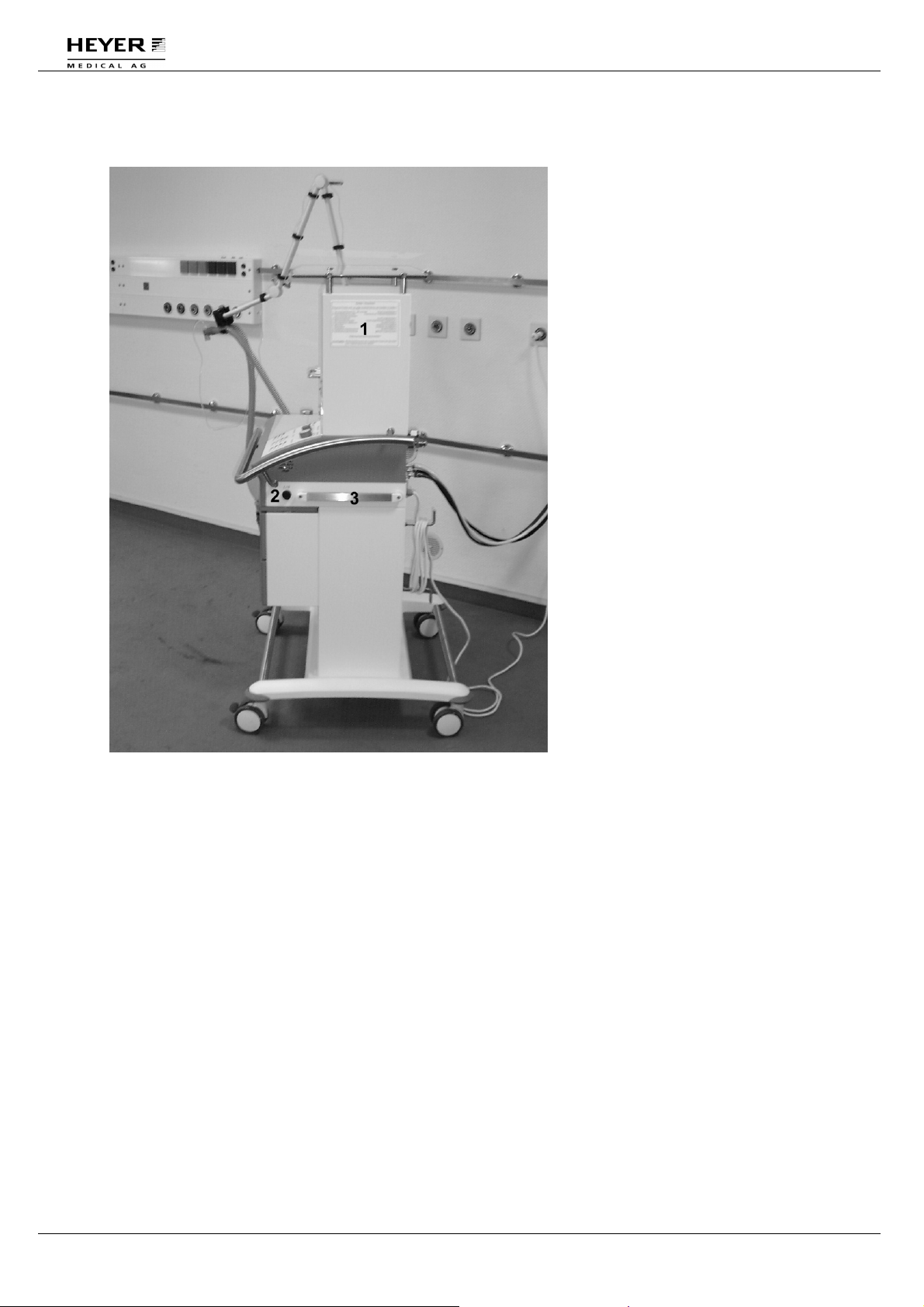
4.1.4 Right side of apparatus
1 Machine operation
checklist
The checklist informs
about several tests which
have to be carried out in
the start-up procedure.
2 Mains switch
With this switch, the
apparatus is switched
on/off and the mains
connection is activated.
During the operation, the
switch remains in the ON
position.
3 Rail mount 25 x 10
Fig. 4 Right side view on the apparatus
22 / 150 HEYER Narkomat+, Operator’s manual Rev. 3.1 - 05/09
Page 23
H E Y E R N a r k o m a t+
4.2 Ventilator unit
1
2
3
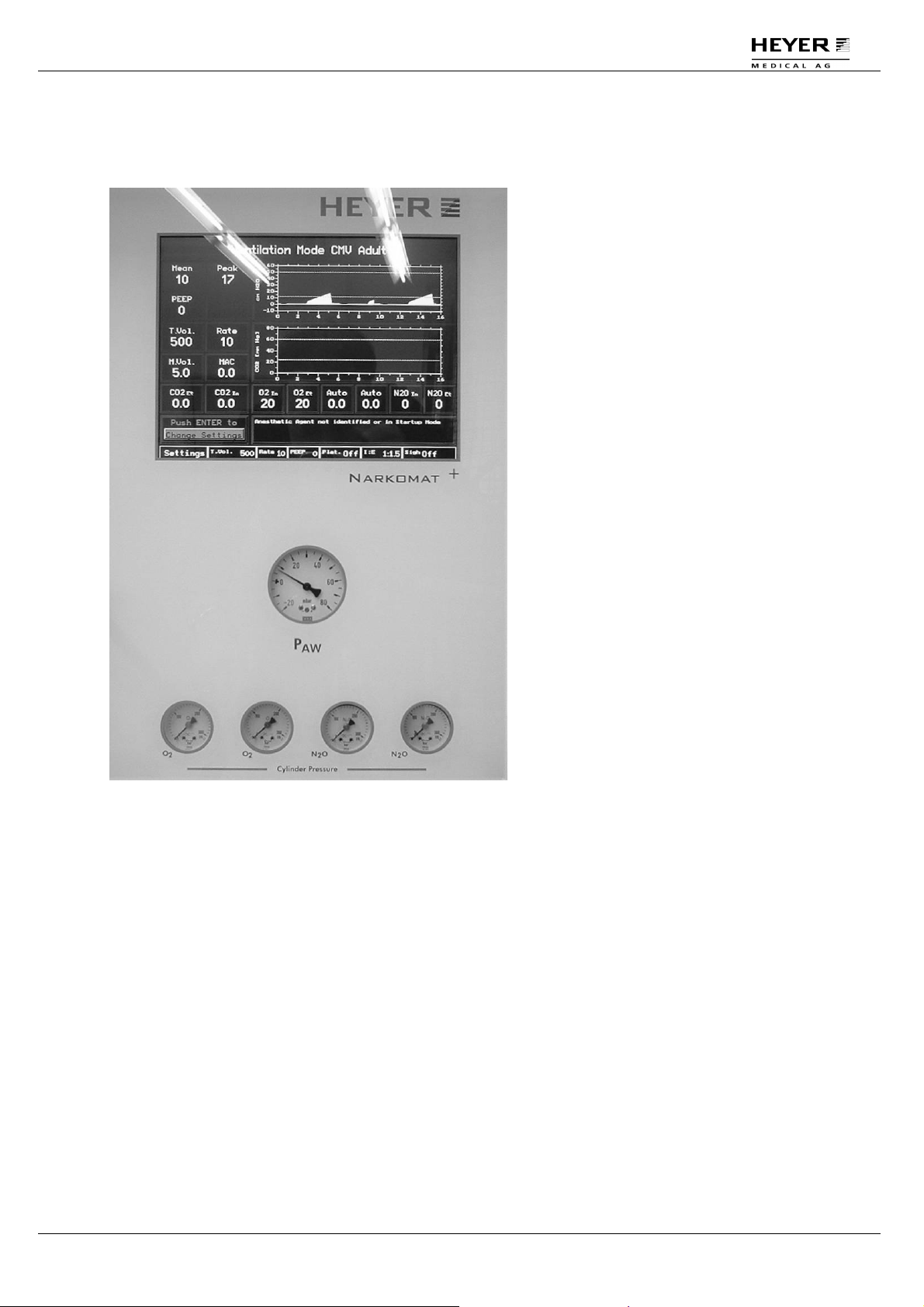
Fig. 5 Ventilator display and airway pressure gauge
1 Ventilator display
The ventilator uses a
color TFT display. This
display is high in contrast,
clearly visible also from
the side view and
provides all measured
values and settings of the
ventilator.
2 Airway pressure
gauge
Shows the airway
pressure on a pressure
gauge within a range of
-20 to 80 cmH2O.
3 Cylinder pressure
gauges
Shows the cylinder
pressure for each
cylinder on a pressure
gauge within a range of
0 to 315 kPa x 100 (315
bar).
Rev. 3.1 – 05/09 HEYER Narkomat+, Operator’s manual 23 / 150
Page 24
H E Y E R N a r k o m a t+
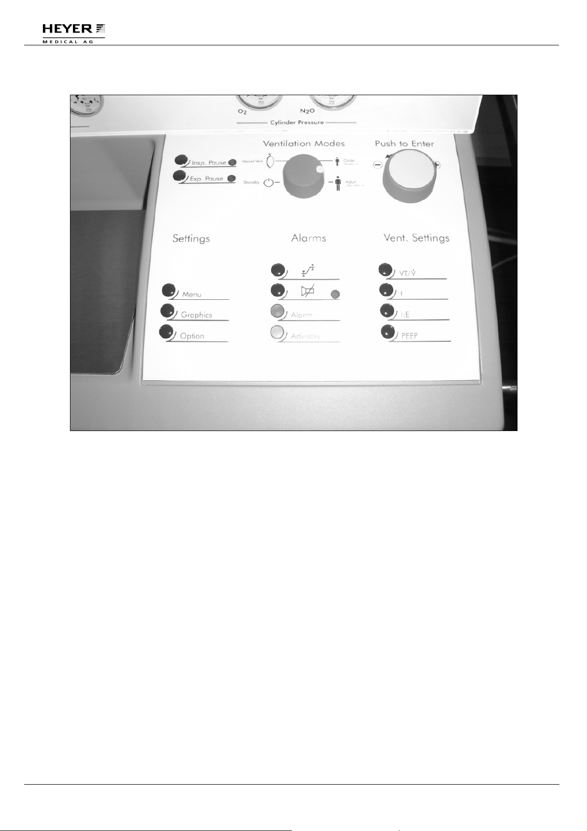
4.2.1 Operating panel, ventilator keyboard
Fig. 6 Operating panel, ventilator keyboard
4.2.1.1 "Ventilation Modes"- selection switch
This switch for the selection of ventilation modes has four positions:
Standby: Position for starting and implementing sensor and system tests.
Manual/spont.: In this position the ventilator is switched to the manual or
spontaneous ventilation mode.
Child (20-400 ml): In this position, the ventilator is switched to the mode for the
controlled ventilation of children.
Adult (300-1400 ml): In this position the ventilator is switched to the mode for the controlled
ventilation of adults.
24 / 150 HEYER Narkomat+, Operator’s manual Rev. 3.1 - 05/09
Page 25

H E Y E R N a r k o m a t+
4.2.1.2 "Push to Enter" - encoder button to change and confirm settings
With this encoder button the different parameter windows can be selected in the display. By
turning the button anti-clockwise or clockwise, the respective windows or selection buttons in
the display are selected. By pushing the direct selection button, functions or further windows
may be selected or opened. Rotary ventilator set-up buttons shown on the display, are also
operated by the direct selection button. The respective parameters are increased in clockwise
direction and decreased in anti-clockwise direction.
In case of changes, the changed settings or selections are confirmed and stored once
the button is pressed.
4.2.1.3 Operating panel keys for insp. pause and exp. pause
Insp. Pause: Upon pressing this key in the CMV mode, the green LED flashes and an
inspiratory pause of up to 5 sec. is inserted at the end of the next inspiration.
In order to terminate the pause early, the key may be pressed a second time,
after which the inspiratory pause is terminated.
Exp. Pause: Upon pressing this key in the CMV mode, the green LED flashes and an
expiratory pause of up to 30 sec. is inserted at the end of the next expiratory.
In order to terminate the pause early, the key may be pressed a second time,
after which the expiratory pause is terminated.
4.2.1.4 "Settings" - panel keys for basic set-up
Menu: This key opens a ventilator display window menu in all ventilation modes and
the standby position. The time and temperature of the patient module are
displayed. The alarm level of the acoustic alarms can be set and the alarm
limits for three personal settings may be stored or loaded. The test option
system display key opens another window in which comprehensive or brief
information may be selected for the result of the compliance test.
Graphics: This key opens a ventilator display graphic window in all ventilation modes
and the standby position. The time axis of the real-time ventilation pressure
and expiratory flow graphics to be displayed can be set to 16, 24 or 32
seconds.
Options This key opens a ventilator display graphic window in all ventilation modes
and the standby position. Here the anesthesia gas, the sample flow and the
displayed CO2 unit can be set. *
In the standby mode the patient module can be unlocked and the gas
measurement can be verified. *
*Only valid with option gas module
Rev. 3.1 – 05/09 HEYER Narkomat+, Operator’s manual 25 / 150
Page 26

H E Y E R N a r k o m a t+
V
V
4.2.1.5 "Alarms" - panel keys and displays for alarms
This key opens a display window in the manual/spontaneous, CMV,
(S)CMV or PCV ventilation modes for setting all available alarm limits.
The respective alarm limits can then be changed to the new settings.
By pressing the limits key a second time, an additional alarm window is
opened with additional adjustable alarm settings. By pressing the limits
key a third time the window is closed and the changed alarm limits are
stored.
This key switches off the sound of the acoustic alarms for a maximum
of 2 minutes. By pressing the key again, the sound is activated again
before the end of the 2 minute period.
4.2.1.6 Vent. Settings" - panel keys for direct selection display windows
For the respective parameters a smaller window is opened for a new setting or the alteration
of existing settings. With the aid of the encoder button, the current parameter setting can be
changed with a rotary display button. The changed setting is confirmed and stored by
pressing the encoder. Or the display window is closed by depressing the key again or
automatically after about 5 sec.
•
VT/
: In the CMV ventilation mode this key opens a display window for
setting the tidal volume VT.
•
In the PCV ventilation mode this key opens a display window
setting the maximum inspiratory flow.
f: This key opens a Rate display window in the CMV ventilation mode for
setting the ventilation frequency Rate.
I:E: This key opens an I:E display window in the CMV ventilation mode for
setting the ventilation time ratio I:E from inspiration to expiration time.
PEEP: This key opens a PEEP display window in the CMV ventilation mode
allowing a PEEP setting.
for
26 / 150 HEYER Narkomat+, Operator’s manual Rev. 3.1 - 05/09
Page 27
H E Y E R N a r k o m a t+
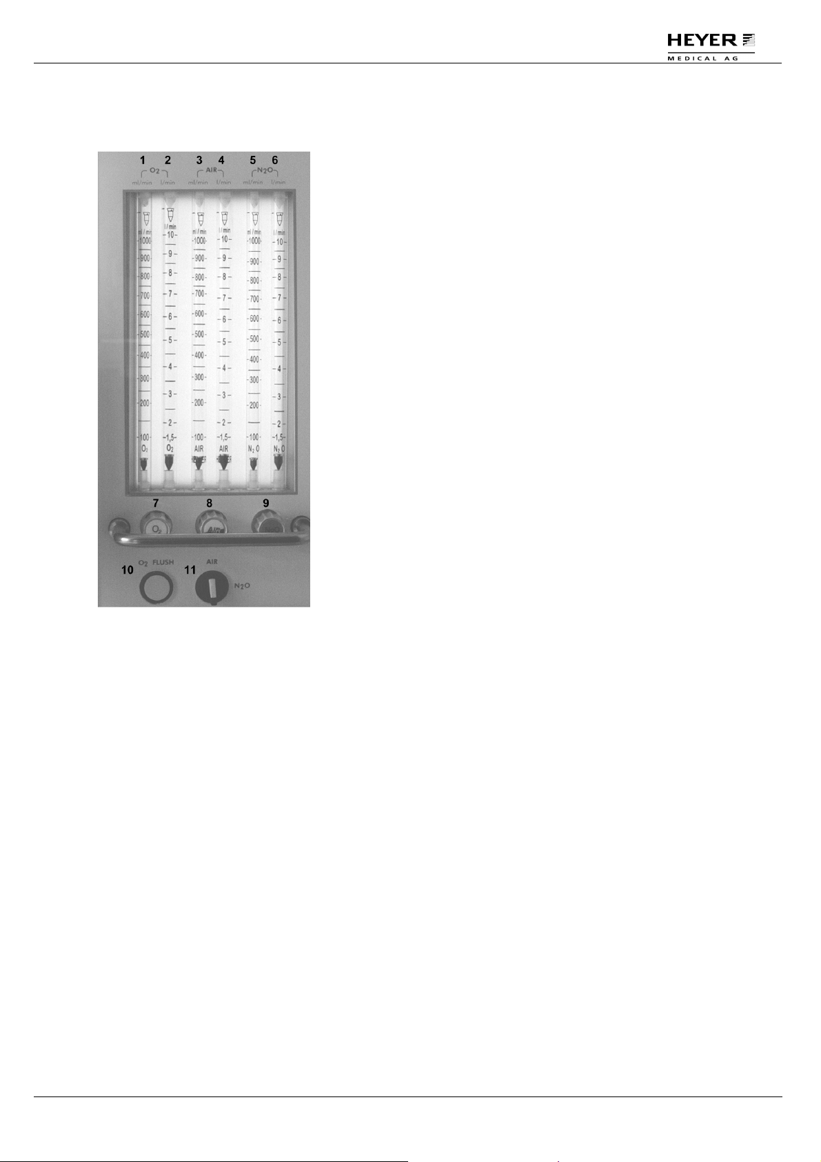
4.3 Flow meter tube block including fresh gas dosing
Fig. 7 Flow meter block including fresh gas dosing
1 Flow meter tube O
2 Flow meter tube O
3 Flow meter tube AIR
with a low measuring range for settings between 0 to 1000 ml/min
2
with a high measuring range for settings between 1,5 and 10 l/min
2
with a low measuring range for settings between 0 to 1000
ml/min
4 Flow meter tube AIR
with a high measuring range for settings between 1,5 and 10
l/min
5 Flow meter tube N2O
with a low measuring range for settings between 0 to 1000
ml/min
6 Flow meter tube N2O
with a high measuring range for settings between 1,5 is 10 l/min
7 Valve spindle for O2 gas dosing
8 Valve spindle for AIR gas dosing
9 Valve spindle for N2O gas dosing
10 O2 bypass
The O2 bypass supplies a high O2 flow (approx. 50 l/min) directly to the fresh gas outlet or
into the patient module. Upon releasing the bypass key, the key returns to its original
position and the O2 bypass is automatically interrupted.
11 N2O/AIR change-over switch
This switch allows the pre-selection of N2O or AIR, which can then be dosed with the
respective valve spindles. The previously set volume flow is retained after switching back
to the same gas type.
Rev. 3.1 – 05/09 HEYER Narkomat+, Operator’s manual 27 / 150
Page 28
H E Y E R N a r k o m a t+
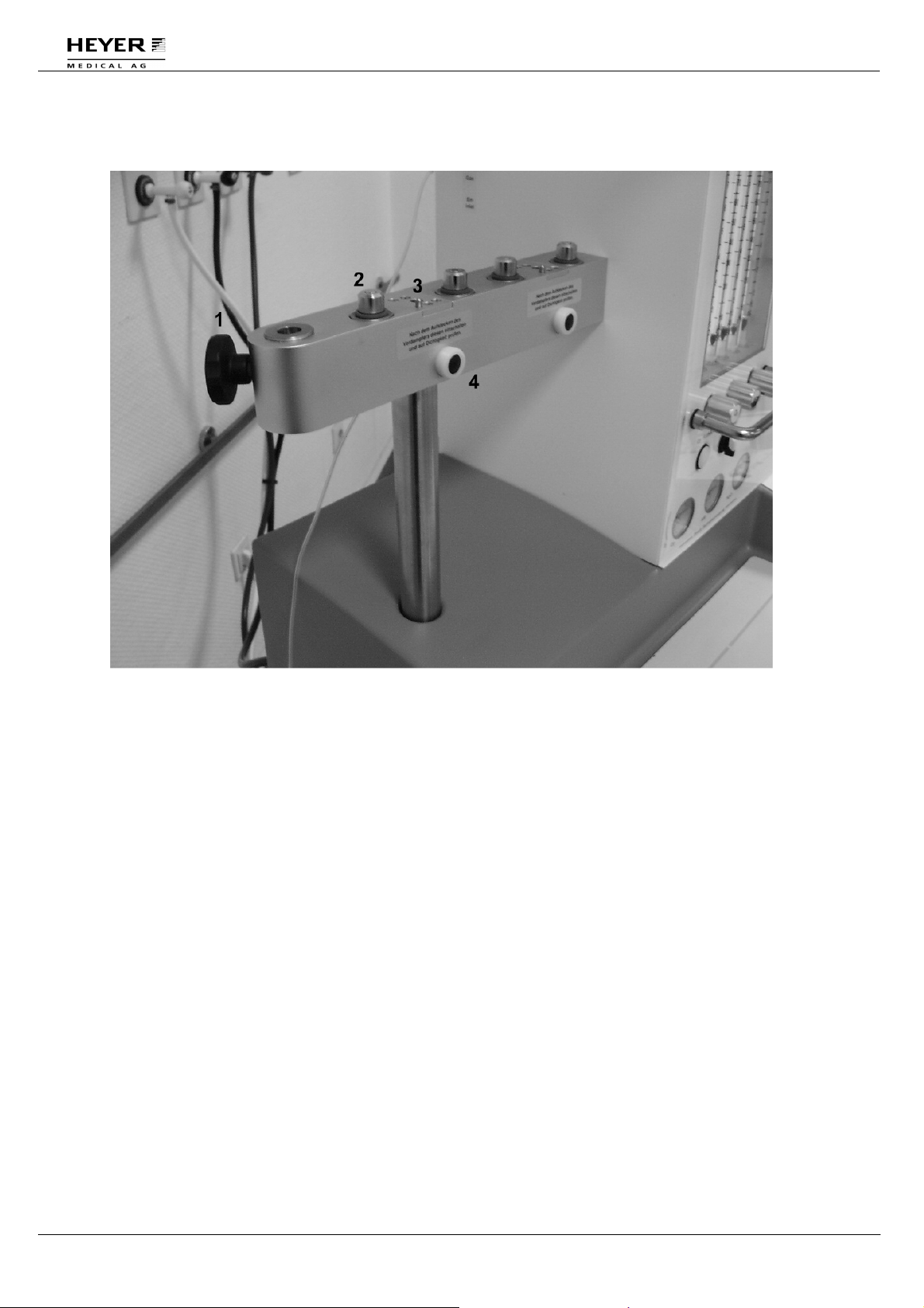
4.4 Vaporizer mounting device
Fig. 8 Vaporizer mounting device
1 Fixing knob for patient arm
2 Valve cartridge of vaporizer mount
3 Locking device
4 Stopping face
28 / 150 HEYER Narkomat+, Operator’s manual Rev. 3.1 - 05/09
Page 29
H E Y E R N a r k o m a t+
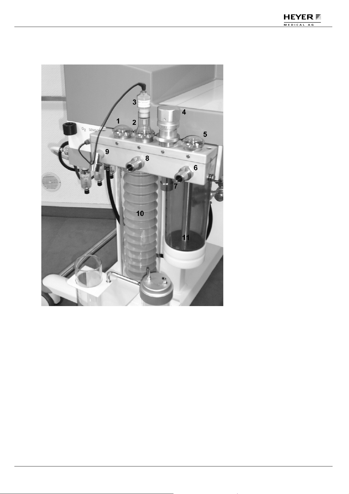
4.5 Patient module (circuit system)
Fig. 9 Patient module (circuit system)
1 Emergency air valve
2 Inspiration valve
3 Oxygen sensor*
(fuel cell)
4 Ventilation pressure valve (APL valve): Including rotary regulator for setting the
pressure control during manual ventilation or for setting it as a 2 cmH2O release valve
during CMV or spontaneous ventilation.
5 Expiration valve
6 Hose connection branch
7 Outlet of ventilation pressure valve
(APL-valve):
The anesthetics gas scavenging system is connected to this point.
8 Hose connection for inspiration branch
9 Hose connection for reservoir/manual ventilation bag
10 Bellows including bellows dome
11 CO
absorber canister
2
*only the apparatus option without the gas module
Rev. 3.1 – 05/09 HEYER Narkomat+, Operator’s manual 29 / 150
Page 30
H E Y E R N a r k o m a t+
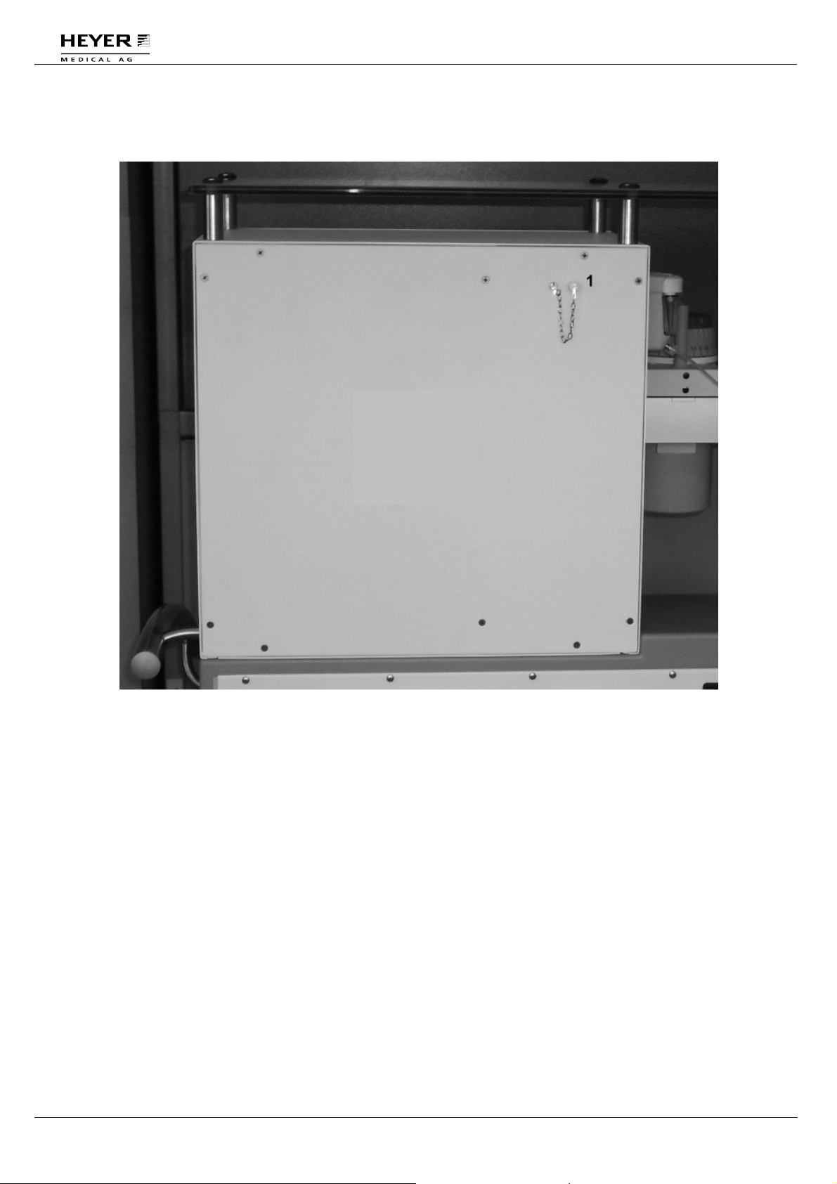
4.6 Sample gas recirculation
Fig. 10 Sample gas recirculation
1 Sample gas recirculation connector*
The gas return line from external monitors operating according to the side stream
procedure are connected to the "Sample gas recirculation" adapter at the rear side. The
sample gas is putted back to the reservoir bag by this adapter.
* only the apparatus option without the gas module
30 / 150 HEYER Narkomat+, Operator’s manual Rev. 3.1 - 05/09
Page 31

H E Y E R N a r k o m a t+
4.7 Vacuum source for bronchial suction (optional)
Fig. 11 Vacuum source
1 Tube clamp for suction tube/finger tip
2 Quick coupling AIR for vacuum source
3
Vacuum source (injector) with vacuum gauge and control knob
4 Connection for tube to suction glass "vacuum" connector
Rev. 3.1 – 05/09 HEYER Narkomat+, Operator’s manual 31 / 150
Page 32

H E Y E R N a r k o m a t+
4.8 Symbols on the Unit
Attention, check the accompanying documents
I/0
On/Off (connection to the power supply)
32 / 150 HEYER Narkomat+, Operator’s manual Rev. 3.1 - 05/09
Page 33

H E Y E R N a r k o m a t+
5 Alarm Messages and Safety Devices
The NARKOMAT+ anesthesia system displays alarm messages on the ventilator display
during operation. The alarm message is displayed until the fault condition that triggered the
alarm is resolved. High priority alarms are displayed against a light background in the alarm
window. Low priority alarms are displayed against a dark background. The switching of the
alarm muting key does not influence the alarm shown on the display.
In the following, all alarm situations that may arise during the different operating conditions
are explained.
There are three priority levels of the alarms:
No. Alarm LEDs Acoustic
1 Continues red Continues tone
2 Red blinking Intermitting tone
3 Yellow blinking
Rev. 3.1 – 05/09 HEYER Narkomat+, Operator’s manual 33 / 150
Page 34

H E Y E R N a r k o m a t+
5.1 Alarm messages direct after the System start
Direct after the switching on and booting of the system, alarm messages are displayed in the
bottom section of the screen. The alarm has to be acknowledged by pushing the encoder
button before the booting procedure continues.
Direct after the switching on
and booting of the system,
alarm messages are
displayed in the bottom
section of the screen. The
operating conditions can be
checked and, if necessary,
errors can be corrected.
Fig. 12 Example of an alarm message during the booting
procedure
34 / 150 HEYER Narkomat+, Operator’s manual Rev. 3.1 - 05/09
Page 35

H E Y E R N a r k o m a t+
5.2 Alarm Messages in Standby
In standby, the alarm messages are display in the middle section of the screen.
In standby, the alarm
messages are display in the
middle section of the screen.
The operating conditions
can be checked and, if
necessary, errors can be
corrected.
Fig. 13 Example of an alarm message during the booting
procedure
Rev. 3.1 – 05/09 HEYER Narkomat+, Operator’s manual 35 / 150
Page 36

H E Y E R N a r k o m a t+
5.3 Compliance test alarm messages
During or after the compliance test, alarm messages are displayed in the middle or top
section of the screen
During or after the
compliance test, alarm
messages are displayed in
the middle or top section of
the screen
The operating conditions
can be checked and, if
necessary, errors can be
corrected.
Fig. 14 Example of a sensor test alarm message
If the system was locked because of a sensor failure, only use the apparatus in case of an
emergency for manual ventilation and contact a service technician if the compliance test fails
repeatedly.
5.3.1 Compliance test alarm messages
Alarm message Significance/ cause Corrective action
System Resistance too high Resistance of patient hoses or
bacteria filter is too high.
Compliance test Passed.
Leak rate is higher than 600
ml/min. Tighten valve rings
The leakage of the circle system
and the patient hoses is higher than
600 ml/min at 40 cm H2O.
Check breathing circuit
Press OK to continue
Replace bacteria filter and
breathing circuit. Use the
Compliance test in Standby /
OPTIONS to retest. If all else
fails call Service.
Ventilator may be used safely
with adequate fresh gas flows.
If necessary use the
Compliance test in Standby /
OPTIONS to retest after
tightening the breathing circuit
and valve rings.
36 / 150 HEYER Narkomat+, Operator’s manual Rev. 3.1 - 05/09
Page 37

H E Y E R N a r k o m a t+
Compliance test alarm messages (continued)
Alarm message Significance/ cause
Compliance out of range The compliance of the connected
patient hoses lies outside the range
of 3.0 to 9.9 ml/cm H2O.
System Error
Cal Required –
Call Service
Data for parameter or alarm limit
settings was not saved correctly,
the data exchange between the
ventilator modules and on-screen
display is faulty or the startup test
for Internal circuit EEPROM has
failed.
Check Diaphragm Valves The system has detected a
pressure increase. The diaphragm
valves may be leaking drive gas
into the circle system.
Pressure Reading out of
tolerance
Perform Compliance Test
The system has detected a fault on
one or both pressure sensors.
when convenient
Flow/Volume Readings not
available
Replace Flow Sensor - Call
Service
During the test, the hotwire sensor
did not pass its test. Sensor may be
faulty.
Flow/Volume Readings not
available
Replace Flow Sensor - Call
Service
During the test, the hotwire sensor
did not pass its test. Sensor may be
faulty.
Valve Error:
Use Manual Ventilation
Call Service
Vent Error:
Use Manual Ventilation
The proportional valve for
generating the ventilation volume
does not function correctly.
The automatic test routine has
detected a processor control fault.
Call Service
Calibrate Breathing System
Perform Compliance Test
when convenient
One or more solenoid valves
actuating the bellows valve have
failed.
Patient module unlocked The Patient module is not adapted
correctly in the docking station.
Corrective action
Replace bacteria filter and
breathing circuit. Use the
Compliance test in Standby /
OPTIONS to retest. If all else
fails call Service.
Retry function. Reboot
machine. If all else fails call
Service.
Remove the Breathing circuit
from the Docking Station and
check the Decoupling and
Expiratory valves for intact
membranes. Replace as
required or call Service.
Perform the Compliance test in
Standby / OPTIONS. If all else
fails call Service.
Retry function. Perform the
Compliance test in Standby /
OPTIONS
Reboot machine. If all else fails
call Service.
Retry function. Reboot
machine. If all else fails call
Service.
Perform the Compliance test in
Standby / OPTIONS. If all else
fails call Service.
Call Service.
Remove the Breathing circuit
from the Docking Station.
Check the Bellows valve
actuation. Perform the
Compliance test in Standby /
OPTIONS. If all else fails call
Service.
Check if the Patient module is
adapted correctly. If else fails,
call service
Rev. 3.1 – 05/09 HEYER Narkomat+, Operator’s manual 37 / 150
Page 38

H E Y E R N a r k o m a t+
5.4 System test alarm messages
During or after the sensor test, alarm messages are displayed in the lower section of the
ventilator display:
If the system cannot create
a sufficient pressure
increase in the breathing
circuit, the following fault
message is for instance
displayed in the lower
section of the system test
window.
Fig. 15 Example of a system test alarm message
38 / 150 HEYER Narkomat+, Operator’s manual Rev. 3.1 - 05/09
Page 39

H E Y E R N a r k o m a t+
System test alarm messages (continued)
Alarm message
System Resistance too high Resistance of patient hoses or
Leakage greater than 200 ml/min The fresh gas system leakage test
Compliance out of range The compliance of the connected
System Error
Cal Required –
Call Service
Calibrate Breathing System
Perform Compliance Test when
convenient
CPU Error:
Use Manual Ventilation Call
Service
O2 Cell is out of range
Replace O2 Sensor
Press OK to Start
O2 concentration too high.
Expose Sensor to room air.
Press OK to start.
Significance/ cause Corrective action
bacteria filter is too high.
has detected a leakage of over
200 ml/min.
patient hoses lies outside the
range of 3.0 to 9.9 ml/cm H2O.
Data for parameter or alarm limit
settings was not saved correctly,
the data exchange between the
ventilator modules and on-screen
display is faulty or the startup test
for Internal circuit EEPROM has
failed.
One or more solenoid valves
actuating the bellows valve have
failed.
The watchdog control system has
detected a failure.
O2 cell is either in a concentration
of O2 that is lower than 21%, is
disconnected from the cable or is
faulty.
O2 cell is either in a concentration
of oxygen that is higher than 21%
or cell is faulty.
Replace bacteria filter and
breathing circuit. Use the
Compliance test in Standby /
OPTIONS to retest. If all else
fails call Service.
Ventilator may be used safely
with adequate fresh gas flows.
Retest after checking the
breathing circuit, tighten valve
rings, o-rings, seals on
vaporizer mounts, bellows
and absorber domes
Replace bacteria filter and
breathing circuit. Use the
Compliance test in Standby /
OPTIONS to retest. If all else
fails call Service.
Retry function. Reboot
machine. If all else fails call
Service.
Remove the Breathing circuit
from the Docking Station.
Check the Bellows valve
actuation. Perform the
Compliance test in Standby /
OPTIONS. If all else fails call
Service.
Call Service.
Expose cell to 21% oxygen,
with its cable plugged in, or
replace the cell.
Expose cell to 21% oxygen or
replace the cell.
Rev. 3.1 – 05/09 HEYER Narkomat+, Operator’s manual 39 / 150
Page 40

H E Y E R N a r k o m a t+
5.5 Alarm messages during normal operation
During normal operation, alarm messages are displayed in the lower section of the ventilation
mode window:
Fig. 16 Example of an alarm message during normal operation
After each activation of the CMV mode, the following alarm message is, for instance,
displayed because the selected minimum airway pressure has not been reached and the
anesthesia gas concentration is not sufficient for identification.
Alarm messages during normal operation (continued)
40 / 150 HEYER Narkomat+, Operator’s manual Rev. 3.1 - 05/09
Page 41

H E Y E R N a r k o m a t+
Alarm message
Significance/ cause Corrective action
CPU Error:
Use Manual Ventilation Call
Service
The watchdog control system has
detected a failure.
Vent Error:
Use Manual Ventilation Call
The automatic test routine has
detected a processor control fault.
Service
High system pressure
Set APL valve to OPEN
The ventilation pressure does not
decrease during expiration.
Valve Error:
Use Manual Ventilation
Call Service
Flow Error:
Use Manual Ventilation
Call Service
The proportional valve for
generating the ventilation volume
does not function correctly.
The internal flow sensor,
measuring the generated
ventilation volume, does not
functioning correctly.
Calibrate Breathing System
Perform Compliance Test
when convenient
One or more solenoid valves
actuating the bellows valve have
failed.
Pressure Reading out of
tolerance
Perform Compliance Test
The system has detected a fault
on one or both pressure sensors.
when convenient
No Drive Gas; Please Check The compressed gas (AIR or O2)
supply with which the drive gas of
the ventilator is generated, has
failed.
Resume Ventilation Drive gas now available after the
ventilator had stopped, because
of a loss of drive gas.
Flow/Volume Readings not
available
Replace Flow Sensor - Call
Service
During the test, the hotwire sensor
did not pass its test. Sensor may
be faulty.
Call Service.
Call Service.
Remove the Breathing circuit
from the Docking Station. Check
Expiratory valve actuation.
Perform the Compliance test in
Standby / OPTIONS. If all else
fails call Service.
Perform the Compliance test in
Standby / OPTIONS. If all else
fails call Service.
Remove the Breathing circuit
from the Docking Station. Check
the Bellows valve actuation.
Perform the Compliance test in
Standby / OPTIONS. If all else
fails call Service.
Perform the Compliance test in
Standby / OPTIONS. If all else
fails call Service.
Check AIR or O2 pressure
supply.
Select ventilation mode. Restart
the ventilation.
Retry function. Reboot machine.
If all else fails call Service.
Rev. 3.1 – 05/09 HEYER Narkomat+, Operator’s manual 41 / 150
Page 42

H E Y E R N a r k o m a t+
Alarm messages during normal operation (continued)
Alarm message
A P N E A No breathing by the patient is
System vented or drive gas
missing
PEEP greater than Pmin The measured PEEP exceeds the
FiO2 lower than FiO2 min The measured FiO2 value is less
Tidal Volume lower than Vt
min
Peak pressure greater than
alarm limit
Peak pressure below alarm
limit
Minute Volume below alarm
limit
PEEP greater than PEEPSetting
FiO2 greater than FiO2 alarm
limit
Check Vent Dial position The Vent dial is in an invalid
Temp Sensor out of tolerance
Check Heating System –
Call Service
Temp Sensor readings not
available
Call Service
Significance/ cause Corrective action
Check connections and patient
detected in manual mode when
measuring the expiratory volume.
breathing. Initial Apnea indication
(beeps) is adjustable to 15, 30, or
45 sec. A steady tone indicates
Apnea after 2 minutes.
The circle system is vented during
the pressure or leak test.
Check the O2 cell is present,
APL valve is set to max (leak
test) and breathing circuit is
connected properly.
Check that APL valve setting is
set Pmin pressure limit.
appropriate. Check Pmin. Alarm
setting.
Check that supplied FiO2 is
than the set minimum oxygen
concentration FiO2 min.
appropriate. Check O2 Alarm
setting.
The measured tidal volume VTE
value is less than the set VTE min.
limit.
Check that Tidal Volume setting
is appropriate. Check Vt min
Alarm setting.
The peak pressure Ppeak
exceeds the set Pmax pressure
limit.
Check that Tidal Volume setting
is appropriate. Lungs deflate
when Pmax is reached. Check
Pmin. Alarm setting.
The peak pressure Ppeak is lower
than the set Pmin pressure limit.
Check that Tidal Volume or
Plateau Pressure setting is
appropriate.
The ventilation minute volume M
vol. is lower than the set M vol.
min. limit.
Check that Minute Volume
setting is appropriate. Check
M.Vol. Alarm setting.
The PEEP is greater than the
PEEP setting.
The measured FiO2 exceeds the
set FiO2 max. oxygen
concentration limit.
Check that PEEP setting is
appropriate.
Check that supplied FiO2 is
appropriate. Check O2 Alarm
setting.
Reposition the vent mode vent
position longer than 3 sec.
dial to a valid position. Reselect
ventilation mode. Restart
ventilator.
The control of the breathing circuit
Call Service at next opportunity.
heating, or the heating mat, is
faulty.
The temperature sensor of the
breathing circuit has failed.
Perform the Compliance test in
Standby / OPTIONS. If all else
fails call Service.
42 / 150 HEYER Narkomat+, Operator’s manual Rev. 3.1 - 05/09
Page 43

H E Y E R N a r k o m a t+
Alarm messages during normal operation (continued)
Alarm message
Fan Error
Check Fan –
Call Service
AC Power lost, using Battery The mains voltage supply has
AC Power lost, using Battery
30 min. remaining
AC Power lost, using Battery
25 min. remaining
AC Power lost, using Battery
20 min. remaining
AC Power lost, using Battery
15 min. remaining
AC Power lost, using Battery
10 min. remaining
AC Power lost, using Battery
5 min. remaining
AC Power lost, using Battery
Battery running low
Use Manual Ventilation
Check Battery – Call Service The battery is empty or defective Check the fuses. Call Service if
Significance/ cause Corrective action
The fan that ventilates the
Call Service at next opportunity.
housing and cools the integral
modules has stopped.
Check AC line cord is plugged
failed, the machine is being
powered by the battery.
into AC outlet. Call Service if
required.
Less than 30 minutes of battery
Plug in AC Line cord.
power available.
Less than 25 minutes of battery
Plug in AC Line cord.
power available
Less than 20 minutes of battery
Plug in AC Line cord.
power available
Less than 15 minutes of battery
Plug in AC Line cord.
power available
Less than 10 minutes of battery
Plug in AC Line cord.
power available
Less than 5 minutes of battery
power available
Mechanical ventilation will
discontinue in approximately 5
minutes. Display and numeric
values will continue until battery
power is exhausted. Patient can
be manually ventilated as long as
there is compressed gas
available.
The power supplied by the battery
is too low for automatic
mechanical ventilation. The
Check AC line cord is plugged
into AC outlet. Call Service if
required.
display will fade within minutes.
required.
Continuous Pressure A continuous ventilation pressure
without significant change of the
Check that APL valve is set to
the CMV/SP position.
pressure value is detected.
Ambient Air Intake; Check
Fresh Gas setting
The emergency air valve in the
patient section has opened; check
the fresh-gas setting and increase
the fresh gas flow, if necessary.
Check if the fresh gas flow is is
sufficient. Check for Leaks.
Check if patient is breathing
Spontaneously. call Service at
next opportunity.
Rev. 3.1 – 05/09 HEYER Narkomat+, Operator’s manual 43 / 150
Page 44

H E Y E R N a r k o m a t+
Alarm messages during normal operation (continued)
Alarm message
Significance/ cause Corrective action
Set APL Valve to CMV/SP
position
Message to remind operators to
set the ventilation pressure valve
(APL) to the CMV/SP position
after activating the CMV mode.
Set the airway pressure limiting
valve (APL) to the CMV/SP
position after activating either
mechanical ventilation mode.
This message also appears if
there is a peep that is higher then
the chosen peep.
Rate lower than f min
The measured ventilation
frequency Rate value lies below
the set f min. limit.
Only in the manual mode.
Increase the ventilation
frequency
Rate greater than f max
The measured ventilation
frequency Rate value exceeds the
set f max. limit.
Only in the manual mode
Decrease the ventilation
frequency
Check Settings The set parameters for CMV
mode ventilation are for an
Check Tidal Volume setting is
appropriate.
inspiratory flow that cannot be
achieved by the machine. The
max. limit is a minute volume of <
20 l/min, or an inspiratory flow <
75 l/min.
Compliance Test bypassed The Startup Compliance test has
been bypassed
Perform the Compliance test in
Standby / OPTIONS as soon as
time allows to ensure the safe
function of the system
44 / 150 HEYER Narkomat+, Operator’s manual Rev. 3.1 - 05/09
Page 45

H E Y E R N a r k o m a t+
Insp. Agent
Insp. Agent
5.5.1 Alarm messages during normal operation with the integrated Gas
Module *
Alarm message
Insp. Agent H I G H
FiO2 L O W ! The measured FiO2 value is less
FiO2 H I G H ! The measured FiO2 exceeds the
CO2 Re-breathing; please
check Absorber
Insp. N2O H I G H
ET CO2 H I G H
ET CO2 L O W
Insp. Agent L O W
Insp. N2O L O W
Gas Monitor Technical Failure
Sampling Line Occlusion
No Patient detected; no
Breathing
Water trap is full, will be full
soon or connection faulty
Significance/ cause Corrective action
The measured Anesthesia agent
concentration is higher than the
set maximum value for the end
Check that supplied Insp. Agent
is appropriate. Check
Alarm setting.
tidal concentration
Check that supplied FiO2 is
than the set minimum oxygen
concentration FiO2 min.
appropriate. Check O2 Alarm
setting.
Check that supplied FiO2 is
set FiO2 max. oxygen
concentration limit.
appropriate. Check O2 Alarm
setting.
The inspiratory CO2 value is too
high
The measured N2O concentration
is higher than the set value N2O
max
Exchange the soda lime. If all
else fails call Service.
Check that supplied N2O is
appropriate. Check N2O Alarm
setting.
The measured CO2 concentration
is higher than the set value CO2
max
Check the soda lime, the
conditions of the patient and the
alarm settings If all else fails call
Service.
The measured CO2 concentration
is lower than the set value CO2
min
Check the conditions of the
patient and the alarm settings If
all else fails call Service.
The measured Anesthesia agent
concentration is lower than the set
minimum value for the inspiratory
Check that supplied Insp. Agent
is appropriate. Check
Alarm setting.
concentration
The measured N2O concentration
is lower than the set value N2O
min
Check that supplied N2O is
appropriate. Check N2O Alarm
setting.
Internal fault in the gas module Call Service
Due to an improper tube
connection, the exact value can
not be measured
Check if the sample tube is
kinked or obstructed. If else fails
exchange the sample tube
The CO2 measurement cannot
detect any breathing or respiration
activities
Check if the sample tube is
connected and check the
conditions of the patient
The water trap is full, nearly full or
the water trap is not connected
correctly
Check if the water trap is
connected correctly or, if full,
exchange it
Rev. 3.1 – 05/09 HEYER Narkomat+, Operator’s manual 45 / 150
Page 46

H E Y E R N a r k o m a t+
Alarm messages during normal operation with the integrated Gas Module*
(continued)
Alarm message
Gas Monitor NOT ready
Anesthetic Agent Mixture
Anesthetic Agent not
identified or in Startup Mode
Anesthetic Agent
Measurement in Startup Mode
*Only valid with option gas module
Significance/ cause Corrective action
Power supply or data
Call Service
communication to the gas module
is defective
The presence of a second
anesthetic agent has been
detected
The concentration of the
anesthetic agent is too low for an
auto identification or the sensor is
in the startup phase and cannot
Wait up to 4 min for the sensor to
warm up. If all else fails call
Service.
deliver the measurements within
the ISO specifications
The sensor is in the startup phase
and cannot deliver the
measurements within the ISO
specifications
Wait up to 4 min for the sensor to
warm up. If all else fails call
Service.
46 / 150 HEYER Narkomat+, Operator’s manual Rev. 3.1 - 05/09
Page 47

H E Y E R N a r k o m a t+
5.5.2 Alarm messages during normal operation with the optional
ventilation mode PCV
Alarm message
Unable to attain target
pressure; Adjust f, flow or I:E
Ratio
PCV Setting not valid
Expiratory time too short
Significance/ cause Corrective action
The inspiration time and/or the
flow is too low for the selected
plateau pressure to be attained
Check that I:E ratio and
breathing frequency setting are
appropriate.
The combination of inspiratory
Change the PCV settings
flow, frequency and I:E ratio
cannot be realized by the
ventilator.
The set expiration time does not
allow the below to refill completely
Check that I:E ratio and
breathing frequency setting are
appropriate.
Rev. 3.1 – 05/09 HEYER Narkomat+, Operator’s manual 47 / 150
Page 48

H E Y E R N a r k o m a t+
5.6 Technical failure alarm message
Alarm message
Major Technical Failure
Switch to Manual Ventilation!
Call Service - Technician
This alarm is not shown in the usual alarm windows of the various displays. Due to its
extremely high priority, this fault is displayed in its own window.
Significance/ cause Corrective action
The ventilator has a serious
technical fault and stops the
controlled ventilation in the CMV
mode.
Call Service
Fig. 17 “Major Technical Failure” alarm message
6 Start-Up and Functional Test
6.1 Preparation of apparatus
1. Install the apparatus in such as way that the touch screen operating panel at the front of
the apparatus is within easy reach and the flow measuring tubes can be easily read.
2. Once the apparatus has been installed in the correct location activate the breaks on the
front rollers to prevent accidental movement.
3. Connect the gas connection lines to the gas connection at the rear of the unit. Check
that the pressure of the gas supply complies with the specifications of the apparatus.
Connect the gas supply by plugging in the connectors in the gas supply sockets.
Ensure that the connectors are not in the park position.
4. Plug the mains cable into a grounded socket. Switch on the power supply using the
mains switch at the right side of the apparatus.
48 / 150 HEYER Narkomat+, Operator’s manual Rev. 3.1 - 05/09
Page 49

H E Y E R N a r k o m a t+
5. Wait until the ventilator display requests the compliance test. If the breathing circuit
should not be connected to the apparatus remove the transportation cover, if
necessary, and slide the breathing circuit into position. After sliding in the breathing
circuit nearly up to the stop, you will need to turn the lever below the docking station
clockwise to adapt the breathing circuit.
6. Next equip the breathing circuit with the bag-in-bottle system, consisting of a bellows
and the bellows dome. Install the CO2 absorber canister. Connect the set of hoses for
the anesthesia gas scavenging to the outlet of the ventilation pressure valve (APLvalve). Connect the hose set of anesthesia gas scavenging to the gas scavenger
installed in the operation theatre.
7. Connect the manual ventilation bag and the respective hose to the breathing circuit.
Connect the set of patient hoses to the insp. and exp. connections.
6.2 Pre-Operation Tests
The tests and examinations described below must be carried out before each system start.
They are also specified on the check list kept at the apparatus.
1. Install and lock the vaporizers to be used on the device.
2. Start the compliance test of the device. Follow the instructions on the ventilator display.
3. Carry out the leak test. The O2 calibration should by carried at least every 30 running
hours Respective instructions are shown on the ventilator display.
4. Ensure that a suitable independent device for manual ventilation (i.e. ambulatory bag)
is available at or near the apparatus.
5. If required start the additional monitoring for CO2 and anesthesia gases ( Not
necessary with the optional integrated gas module) and if available ECG and check
function according to the respective operating instructions. The gas return line from
monitors operating according to the side stream procedure should be connected to
the connection at the rear side labeled as "Sample gas recirculation".
6. Ensure via a manual test that the APL valve does not allow a pressure greater than 100
cmH2O
Rev. 3.1 – 05/09 HEYER Narkomat+, Operator’s manual 49 / 150
Page 50

H E Y E R N a r k o m a t+
6.3 Sample Tube Connection (optional integrated Gas
Module)
WARNING
The gas measurement tube system at the monitor must be connected before putting the
apparatus into use or changing the flow rate. Otherwise the apparatus might falsely detect a
tube blockage.
WARNING
Use only the original tube system as measuring tube. If a different tube system is used, faulty
measurements can occur due to condense water and anesthesia gases. Condensed water
can also damage the internal sensors.
WARNING
Ensure the sample tube is going direct upward from the y-piece to avoid condense water
going into the system.
50 / 150 HEYER Narkomat+, Operator’s manual Rev. 3.1 - 05/09
Page 51

H E Y E R N a r k o m a t+
6.4 System Start
After switching on the apparatus the message “Please wait...” appears for approx. 20 seconds
while the software is loading. During the booting process the apparatus shows two displays for
the system start and the automatic apparatus test. The system then asks the operator to carry
out the sensor test
Fig. 18 First display message during system start
Fig. 19 Second display message during system start
Rev. 3.1 – 05/09 HEYER Narkomat+, Operator’s manual 51 / 150
Page 52

H E Y E R N a r k o m a t+
6.5 Battery Control
After the apparatus has been switched on, the charging status of the battery will be checked.
Depending on the charging status of the battery, the apparatus may start charging the battery
which can take up to 7 hours.
6.6 Sensor Test
After the automatic system start has been completed, the following display for implementing
the sensor test appears.
Fig. 20 Display before sensor test
In the case of an emergency, the sensor test can be bypassed via turning the selector switch.
Otherwise follow the instructions of the ventilator display and activate by pressing the “START”
button.
The system now checks and calibrates all sensors, i.e. the expiratory flow sensor and the
pressure sensors. Also the internal sensors of the ventilator drive and the active components
such as pneumatics control valves are checked during the compliance test.
The breathing circuit, patient connection hoses, the Y-piece etc. are also tested for leaks.
Furthermore the system compliance to which in particular also the patient hoses contribute is
detected during the compliance test.
52 / 150 HEYER Narkomat+, Operator’s manual Rev. 3.1 - 05/09
Page 53

H E Y E R N a r k o m a t+
Compliance test (continued)
During the compliance test a display message confirms that the test is running.
After the successful sensor test the text message "Sensor Test ok" with information about
leakage rate and system compliance appears.
Fig. 21 Display after the sensor test
After the successful completion of the sensor test, a similar test, the compliance test can be
carried out in the standby mode. Apart from detecting the system compliance this compliance
test also checks for leaks in the patient module, patient connecting hoses, Y-piece, etc. The
compliance test should be carried out, if the patient tubes were exchanged against others,
with a relevant difference in the tube compliance.
Rev. 3.1 – 05/09 HEYER Narkomat+, Operator’s manual 53 / 150
Page 54

H E Y E R N a r k o m a t+
6.6.1 Compliance Test
Fig. 22 Display prior to the compliance test
Follow the instructions of the ventilator display and activate by pressing the “START” button.
54 / 150 HEYER Narkomat+, Operator’s manual Rev. 3.1 - 05/09
Page 55

H E Y E R N a r k o m a t+
Compliance test (continued)
Fig. 23 Display after the compliance test as extended information
As extended information to the test result of a compliance test, the leakage of the patient
module at 40 cmH2O and the detected system compliance is displayed.
Fig. 24 Display after the compliance test as pass/fail information
Rev. 3.1 – 05/09 HEYER Narkomat+, Operator’s manual 55 / 150
Page 56

H E Y E R N a r k o m a t+
Compliance test (continued)
The menu window allows the operator to select whether the result should be displayed as a
brief pass/fail message or if extended information should be displayed.
By activating the “menu” key, the menu window is opened. Under the sub-menu “System test
options” and “Sensor test options” “Pass/Fail Info” or “Extended Info” can be selected.
6.7 System Test
Once the successful sensor test is confirmed with the “Quit” display key, the system test
selection screen is displayed.
Fig. 25 System test selection display
Only in emergencies, where the system is required immediately, should the system test be
skipped. The system test involves a calibration of the oxygen sensor and a fresh-gas system
leak test and should be carried out during a correct system start.
* Only valid with option gas module
56 / 150 HEYER Narkomat+, Operator’s manual Rev. 3.1 - 05/09
Page 57

H E Y E R N a r k o m a t+
System test (continued
)*
Fig. 26 Display of system test selection sub-menu
Both tests should be carried out during the start of the system; select the respective system test
sub-menu by turning the encoder button. Confirm the selection by pressing the encoder on the
“Run” display key.
* The oxygen calibration is not valid with the apparatus option with integrated gas module
Rev. 3.1 – 05/09 HEYER Narkomat+, Operator’s manual 57 / 150
Page 58

H E Y E R N a r k o m a t+
6.7.1 O2 sensor calibration*
When starting the O2 sensor calibration the following display appears.
Fig. 27 First display message of O2 sensor calibration
Pull the O2 sensor out of the inspiration valve cap. For calibration, place the sensor into the
calibration adapter in ambient air left near the port of the O2 sensor cable.
* The oxygen calibration is not valid with the apparatus option with integrated gas module
58 / 150 HEYER Narkomat+, Operator’s manual Rev. 3.1 - 05/09
Page 59

H E Y E R N a r k o m a t+
O2 sensor calibration (continued)*
Fig. 28 Second display message of O2 sensor calibration
In order to allow sufficient time for aerating the O2 sensor in ambient air, a 15 second
countdown is displayed in a calibration start window.
* The oxygen calibration is not valid with the apparatus option with integrated gas module
Rev. 3.1 – 05/09 HEYER Narkomat+, Operator’s manual 59 / 150
Page 60

H E Y E R N a r k o m a t+
O2 sensor calibration (continued)*
During the calibration of the O2 sensors a window providing information about the progress of
the calibration process appears.
Fig. 29 Third display message of O2 sensor calibration
* The oxygen calibration is not valid with the apparatus option with integrated gas module
60 / 150 HEYER Narkomat+, Operator’s manual Rev. 3.1 - 05/09
Page 61

H E Y E R N a r k o m a t+
O2 sensor calibration (continued)*
The result of the O2 sensor calibration is then displayed as follows:
Fig. 30 Fourth display message of O2 sensor calibration
Remove the O2 sensor from the calibration adapter and reinsert it in the inspiration valve cap.
This completes the calibration of the O2 sensor.
* The oxygen calibration is not valid with the apparatus option with integrated gas module
Rev. 3.1 – 05/09 HEYER Narkomat+, Operator’s manual 61 / 150
Page 62

H E Y E R N a r k o m a t+
6.7.2 Leak Test Fresh Gas Delivery System
To carry out a leak test for the entire fresh gas system, select menu item “Leak Test Fresh Gas
Delivery System” on the display by turning and pressing the encoder button.
Fig. 31 Display prior to the fresh gas system leak test
Follow the instructions on the ventilator display. Connect the patient hoses and the hose of the
reservoir/manual ventilation bag to the Y piece. Set the ventilation pressure valve (APL) to max.
and start the leak test by activating the display key “Push to enter” by pushing the encoder
button.
Apart from the patient module, patient connection hoses, the Y piece, etc., the leak test of the
fresh gas system checks also the flow meter tube block, the vaporizer mount and the vaporizers
if activated , absorber canister, manual ventilation hose and ventilation pressure valve (APL) for
any leaks.
62 / 150 HEYER Narkomat+, Operator’s manual Rev. 3.1 - 05/09
Page 63

H E Y E R N a r k o m a t+
Leak Test Fresh Gas Delivery System (continued)
During the fresh gas system leak test, a message confirming that the test is carried out, is
displayed. After a successful fresh gas system leak test, the following window is displayed.
Fig. 32 Display after the Leak Test Fresh Gas Delivery System
Return the hoses of the patient module to their normal condition and reconnect the
reservoir/manual ventilation bag to its hose. Return the ventilation pressure valve to the
CMV/SP position. The fresh gas system leak test has now been completed.
Leave the system test window by selecting the display key “Quit” by pressing the encoder
button.
The ventilator is now operational after the completion of the sensor and system test and
observation of the checklist test points. The Standby window of the normal operating mode is
displayed.
In the following section 7 “Operation in the individual functions” this window is described
under section 7.1 “Standby mode”.
Rev. 3.1 – 05/09 HEYER Narkomat+, Operator’s manual 63 / 150
Page 64

H E Y E R N a r k o m a t+
6.8 Gas module verification*
The verification mode can be called up by pressing the button “options” on the display. For
Verification, the selection switch must be in the “standby” position.
Following display will appear:
Fig. 33 Display of the gas module verification
A calibration of the gas module is not necessary because it is maintenance free. Should a
value of the gas measurement be outside of the tolerance, call an authorized service
technician.
*only for apparatus option with integrated gas module
64 / 150 HEYER Narkomat+, Operator’s manual Rev. 3.1 - 05/09
Page 65

H E Y E R N a r k o m a t+
Gas module verification (continued)*
The verification procedure is described step by step on the screen.
WARNING:
Use only the recommended verification gas and pressure regulator. If using a different
pressure regulator, reinsure that the sample gas flow rate is about 300 ml/min. A to high or to
low flow rate can lead to faulty readings.
Fig. 34 Connection of the tube system to the verification gas bottle
Fig. 35 Display No. 1 for gas measurement verification
*only for apparatus option with integrated gas module
Rev. 3.1 – 05/09 HEYER Narkomat+, Operator’s manual 65 / 150
Page 66

H E Y E R N a r k o m a t+
Gas module verification (continued)*
Fig. 36 Display No. 2 for gas measurement verification
1. Connect the gas measurement tube to the verification gas bottle
2. Open the Valve of the verification gas bottle
3. Confirm “start” through turning and pressing the encoder button.
*only for apparatus option with integrated gas module
66 / 150 HEYER Narkomat+, Operator’s manual Rev. 3.1 - 05/09
Page 67

H E Y E R N a r k o m a t+
Gas module verification (continued)*
Fig. 37 Display No. 3 for gas measurement verification
To ensure the correct display of the values, a zeroing of the gas module is performed first.
The maximum time for a zeroing is 1 min. Do not press the „Quit“ button during this time.
*only for apparatus option with integrated gas module
Rev. 3.1 – 05/09 HEYER Narkomat+, Operator’s manual 67 / 150
Page 68

H E Y E R N a r k o m a t+
Gas module verification (continued)*
After the zeroing is completed, open the gas cylinder valve.
Fig. 38 Display No. 4 for gas measurement verification
*only for apparatus option with integrated gas module
68 / 150 HEYER Narkomat+, Operator’s manual Rev. 3.1 - 05/09
Page 69

H E Y E R N a r k o m a t+
Gas module verification (continued)*
If continues values are being displayed, activate the button quit and close the valve of the
verification gas bottle.
Fig. 39 Display No. 5 for gas measurement verification
*only for apparatus option with integrated gas module
Rev. 3.1 – 05/09 HEYER Narkomat+, Operator’s manual 69 / 150
Page 70

H E Y E R N a r k o m a t+
Gas module verification (continued)*
Compare the display results with the values printed on the verification bottle.
Fig. 40 Display No. 6 for gas measurement verification
Activate the button “finalize verification“ to return to the options menu.
*only for apparatus option with integrated gas module
70 / 150 HEYER Narkomat+, Operator’s manual Rev. 3.1 - 05/09
Page 71

H E Y E R N a r k o m a t+
7 Operation in the Individual Functions
The preparation and operation of the system up to the standby mode is described in section 6
“Start-up and functional test” and its sub-sections. The following sections describe how to
operate the system for the various ventilation modes in the standby mode and the operating
modes.
Fig. 41 Control panel
Rev. 3.1 – 05/09 HEYER Narkomat+, Operator’s manual 71 / 150
Page 72

H E Y E R N a r k o m a t+
7.1 Standby mode
This is the normal operating mode prior to switching on a ventilation mode or in between
ventilation operations. The system returns to this mode after the sensor test and the fresh gas
system leak test have been carried out. The display shows the following window:
Fig. 42 Standby mode display
The ventilator display shows the current time, the total number of system operating hours and
the status of the system tests.
72 / 150 HEYER Narkomat+, Operator’s manual Rev. 3.1 - 05/09
Page 73

H E Y E R N a r k o m a t+
7.1.1 Standby mode menu window
The standby mode menu window is opened by pressing the "Menu" key on the control panel.
The screen displays the following:
Fig. 43 Standby mode menu window
The menu window shows the measured temperature of the heated patient module.
The system time is shown in hours, minutes and seconds.
Using the “Sound level” display regulator the volume of the acoustic alarms can be preset
from 1 to 10. This setting will remain stored until the next system start. In the
Manual/spontaneous mode the alarm acoustic is automatically set to “0”. When leaving the
Manual/spontaneous mode, the alarm acoustic is automatically set to the previous set value.
The display keys "Clock Set", "Load/save" and "System Test Options" open further submenus determining further basic settings.
Rev. 3.1 – 05/09 HEYER Narkomat+, Operator’s manual 73 / 150
Page 74

H E Y E R N a r k o m a t+
Standby mode menu window (continued)
By activating the display key "Clock Set", the window "Set time" is opened.
Fig. 44 "Set time" within the menu window
The options of this window can be selected by turning the encoder button and can be
activated for setting different values by pressing the encoder button.
Turning the encoder anti-clockwise reduces, turning it clockwise increases the value.
To quit the respective option, press the encoder button again.
The new date or time settings are confirmed with “OK” and will then be stored in the system.
To quit the "Set date and time" window, the display key "Cancel" is pressed.
74 / 150 HEYER Narkomat+, Operator’s manual Rev. 3.1 - 05/09
Page 75

H E Y E R N a r k o m a t+
Standby mode menu window (continued)
By activating the "Load/save" display key, the window "Load and Save private Alarm Limits” is
opened.
Here you can save the save the alarm limits which were set in the ventilation mode, or recall
alarm limits which were previously saved.
Fig. 45 "Load/save personal alarm limits" within the menu window
Using following scheme, you can load or save your personal alarm limits:
1. Choose one of the four available memory slots through turning and pressing the
encoder button in the panel “Memory Slot”. The saved alarm limits will be shown in
the menu.
2. If you wish to save the currently set alarm limits, confirm it through turning and
pressing the encoder button in the panel “Memory Slot”. Please notice that you will
overwrite settings which have saved in this slot previously
3. If you want to use previously saved alarm settings, confirm this slots through turning
and pressing the encoder button in the panel “Load”.
4. You can leave the menu "Load and Save private Alarm Limits” slots through turning
and pressing the encoder button in the panel “Quit”.
Note: Due to safety reasons, the system will activate the default settings after every new
start
Rev. 3.1 – 05/09 HEYER Narkomat+, Operator’s manual 75 / 150
Page 76

H E Y E R N a r k o m a t+
Standby mode menu window (continued)
By confirming the “System test options" key, a window bearing the same name is opened.
Fig. 46 "System test options“ within the menu window
Through selecting and confirming with the encoder button:
1. you can switch the “sensor test” between the options “Extended Info” and “short Info”.
2. the window “System Tests” can be called up.
3. the “System Compliance” can be checked. This test, which determines the system
compliance, should be done when e.g. the ventilation tubes are changed between
two patients and their compliance have a significant difference.
This window can be closed and the settings saved through the button “Quit”.
76 / 150 HEYER Narkomat+, Operator’s manual Rev. 3.1 - 05/09
Page 77

H E Y E R N a r k o m a t+
7.1.2 Standby mode graphics window
The standby mode graphic window is opened by pressing the "Graphics" key on the operating
panel. The following window is displayed.
Fig. 47 Standby mode graphic settings window
The graphic window allows the setting of the time axis for the display of the ventilation
pressure and expiratory flow or CO2 capnogram real-time curves.
16, 24 or 32 seconds can be set as values. 16 seconds is the default setting.
The desired time axis representation for the real time curves can be chosen by selecting the
respective screen key.
By pressing the "Graphics" key for the second time, the window is closed again and the
selected setting is stored.
Rev. 3.1 – 05/09 HEYER Narkomat+, Operator’s manual 77 / 150
Page 78

H E Y E R N a r k o m a t+
7.1.3 Standby mode options window
The "Options" window in the standby mode is opened by pressing the “Options” key on the
operating panel. The following window is displayed:
Fig. 48 Stand-by mode options display
The patient module can be unlocked by pressing the "unlock" screen key and is then
unlocked from the apparatus by the integral motor drive.
If the patient module has been removed, the display key shows "unlocked".
The patient module is also reconnected by the motor drive. The motor starts automatically,
once the patient section is sufficiently pushed into the apparatus. Upon pressing the "Options"
key again, the window is closed.
In the field “Gas Measurement“ the date of the last verification is displayed. Activating the
button “verify“ opens the menu fort the Gas verification.
78 / 150 HEYER Narkomat+, Operator’s manual Rev. 3.1 - 05/09
Page 79

H E Y E R N a r k o m a t+
7.1.4 Standby mode screen saver function
If the unit is switched to standby mode for longer than 10 minutes without any operation of a
key or selection switch, the display is switched dark. The text line "Press ENTER for Standby
screen" is displayed on different positions of the display. To deactivate this screen saver
function just press or turn the encoder button.
Fig. 49 Screen saver
Rev. 3.1 – 05/09 HEYER Narkomat+, Operator’s manual 79 / 150
Page 80

H E Y E R N a r k o m a t+
7.2 Control Panel Keys in the Ventilation Modes CMV /
(S)CMV / PCV * Adult / Child
Described is only the ventilation mode CMV-Adult. Differences in the ventilation CMV-Child
will be explained specifically.
(The screen titles change according to the ventilation modes CMV / (S)CMV / PCV * Adult /
Child)
7.2.1 Menu-Window in the Ventilation Modes CMV / (S)CMV / PCV *
Adult / Child
Fig. 50 Menu-Window in the ventilation mode CMV-Adult
The menu window shows the measured temperature of the heated patient module.
The system time is shown in hours, minutes and seconds.
Using the “Sound level” display regulator the volume of the acoustic alarms can be preset
from 1 to 10. This setting will remain stored until the next system start.
The display keys "Clock Set", "Load/save" and "System Test Options" open further sub-
menus determining further basic settings.
* The ventilation modes (S)CMV / PCV are optional.
80 / 150 HEYER Narkomat+, Operator’s manual Rev. 3.1 - 05/09
Page 81

H E Y E R N a r k o m a t+
7.2.2 Graphic Window in the Ventilation Modes CMV / (S)CMV / PCV *
Adult / Child
Fig. 51 Graphic-Window in the ventilation mode CMV-Adult
The graphic window allows the setting of the time axis for the display of the ventilation
pressure and expiratory flow or CO2 capnogram real-time curves.
16, 24 or 32 seconds can be set as values. 16 seconds is the default setting.
Expiratory flow or CO2 capnogram real-time curves can be chosen for the lower graphic
By pressing the "Graphics" key for the second time, the window is closed again and the
selected setting is stored.
* The ventilation modes (S)CMV / PCV are optional.
Rev. 3.1 – 05/09 HEYER Narkomat+, Operator’s manual 81 / 150
Page 82

H E Y E R N a r k o m a t+
7.2.3 Options Window in the Ventilation Modes CMV / (S)CMV / PCV *
Adult / Child
Fig. 52 Options-Window in the ventilation mode CMV-Adult
Through selecting and confirming the encoder button the used anesthesia gas can be defined
and a sample flow can be set.
The display of the CO2 unit can be changed to mmHg or %.
* The ventilation modes (S)CMV / PCV are optional.
82 / 150 HEYER Narkomat+, Operator’s manual Rev. 3.1 - 05/09
Page 83

H E Y E R N a r k o m a t+
7.2.4 Automatic Anesthetic Agent and Agent Mixture Identification *
The gas module incorporates automatic anesthetic agent and agent mixture identification.
The data of the agent measurement is displayed as follows:
Anesthetic
Agent
Identification
Automatic
Automatic
Automatic Agent identified
Automatic
Specific agent
elected
Specific agent
elected
** In Startup mode
*** The accuracy of all gas measurements corresponds to the requests of the ISO 11196
(Accuracy of the indicated reading for Anesthetic agents) and ISO 9918 (Capnometers for
use with humans, requirements) the latest 4 min after switching on the unit.
Accuracy (ISO):
CO2 : +/- 0,5 %
O2 : +/- 3%
Agent : +/-0,15%
N2O : +/- 2%
**** The minimum concentration for the identification of anesthetic agents is approx. 0,3
Vol%.
* only for apparatus option with integrated gas module
Status of the
measurement
Startup Mode **or
insufficient
accuracy ***
concentration of
the anesthetic
agent is too low
for an auto
identification ****
The concentration
of an 2nd agent
has become so
high that the
concentration of
the 1st agent
cannot be
measured
accurately
Startup Mode **or
insufficient
accuracy ***
Specific agent
elected
Name of the
Agent
Auto
Auto
Hal./Enfl./Isofl./
Sev./Des.
Hal./Enfl./Isofl./
Sev./Des.
Hal./Enfl./Isofl./
Sev./Des.
Concentration Color Error Message
--.-
Concentration
value
Concentration
value
White
White
Color
coded
Concentration
value of the 1st
anesthetic
agent
--.-
Concentration
value
Color
coded
Color
coded
Anesthetic
Agent not
identified or in
Startup Mode
Anesthetic
Agent not
identified or in
Startup Mode
Anesthetic
Agent Mixture
Anesthetic
Agent
Measurement
in Startup Mode
Rev. 3.1 – 05/09 HEYER Narkomat+, Operator’s manual 83 / 150
Page 84

H E Y E R N a r k o m a t+
Automatic Anesthetic Agent and Agent Mixture Identification (continued)
Anesthetic Agent and MAC values are color coded as follows:
Gas Abbreviation Color Coding
Halothane Hal. Red
Enflurane Enfl. Orange
Isoflurane Isofl. Purple
Sevoflurane Sev. Yellow
Desflurane Des. Blue
No gas identified Auto White
After the unit has been switched on, the gas module is in the startup mode for approx. 4 min.
During this period following rules apply:
Cold Start:
Time Relative
Accuracy
Event
Time
(Min) (Min) Agent 1/2 N2O CO2
00:00 00:12 - - - Communication
not possible
00:12 00:12 Not ready Not ready Not ready
00:20 00:20 Start phase Start phase Start phase
00:40 00:20 Start phase Unknown Reduced
accuracy
Start phase Start phase Start phase 02:50 02:20
Zero in Progress Zero in Progress Zero in Progress
03:00 00:10 Start phase Reduced
accuracy
04:00 01:00 Start phase Reduced
accuracy
Reduced
accuracy
Reduced
accuracy
Zeroing required
04:00 00:00 Zeroing in
progress
04:30 00:30 ISO accuracy ISO accuracy ISO accuracy
Zeroing completed
124:00 120:00 ISO accuracy ISO accuracy ISO accuracy Zeroing required
84 / 150 HEYER Narkomat+, Operator’s manual Rev. 3.1 - 05/09
Page 85

H E Y E R N a r k o m a t+
V
7.2.5 Panel Key VT/
Child
•
in the Ventilation Modes CMV / (S)CMV Adult /
Fig. 53 Vt adjustment in the ventilation mode CMV Adult
The Menu window shows the screen adjustment Vt for the setting of the tidal volume in ml
during the controlled ventilation.
This adjustment is stored until the unit is switched off.
The window closes after pressing the encoder button or automatically after 10 s.
Rev. 3.1 – 05/09 HEYER Narkomat+, Operator’s manual 85 / 150
Page 86

H E Y E R N a r k o m a t+
V
V
V
7.2.6 Panel Key VT/
•
in the Ventilation Mode PCV Adult / Child
Fig. 54
&
adjustment in the ventilation mode PCV Adult
The Menu window shows the screen adjustment
&
for the setting of the maximum inspiratory
flow in l/min during the controlled ventilation.
This adjustment is stored until the unit is switched off.
The window closes after pressing the encoder button or automatically after 10 s.
86 / 150 HEYER Narkomat+, Operator’s manual Rev. 3.1 - 05/09
Page 87

H E Y E R N a r k o m a t+
7.2.7 Panel Key f in the Ventilation Modes CMV / (S)CMV / PCV Adult /
Child
Fig. 55 Rate adjustment in the ventilation mode CMV Adult
The Menu window shows the screen adjustment f for the setting of the ventilation rate in
1/min.
This adjustment is stored until the unit is switched off.
The window closes after pressing the encoder button or automatically after 10 s.
Rev. 3.1 – 05/09 HEYER Narkomat+, Operator’s manual 87 / 150
Page 88

H E Y E R N a r k o m a t+
7.2.8 Panel Key I:E in the Ventilation Modes CMV / (S)CMV / PCV Adult /
Child
Fig. 56 I:E adjustment in the ventilation mode CMV Adult
The Menu window shows the screen adjustment I:E for the setting of the inspirationexspiration time ratio
This adjustment is stored until the unit is switched off.
The window closes after pressing the encoder button or automatically after 10 s.
88 / 150 HEYER Narkomat+, Operator’s manual Rev. 3.1 - 05/09
Page 89

H E Y E R N a r k o m a t+
7.2.9 Panel Key PEEP in the Ventilation Modes CMV / (S)CMV / PCV
Adult / Child
Fig. 57 PEEP adjustment in the ventilation mode CMV Adult
The Menu window shows the screen adjustment PEEP for the setting of the PEEP in cmH2O.
This adjustment is stored until the unit is switched off.
The window closes after pressing the encoder button or automatically after 10 s.
Rev. 3.1 – 05/09 HEYER Narkomat+, Operator’s manual 89 / 150
Page 90

H E Y E R N a r k o m a t+
7.3 “Manual/spontaneous” ventilation mode
For a manual ventilation or the application of the system for spontaneous ventilation, set the
selection switch of the operating panel to "Manual/spontaneous".
7.3.1 “Manual/spontaneous” ventilation mode
In the ventilation mode “Manual/spontaneous” the display informs you about the measured
values for pressure, flow or volume, ventilation frequency and gas concentration. The
displayed alarms will appear below the real time curves.
Fig. 58 "Manual/spontaneous settings" display 1
In the panels for the measurement values the following will be displayed:
Mean Average pressure in cmH2O
PEEP Positive end expiratory pressure in
cmH2O
T. Vol. Tidal volume in ml
M. Vol. Respiratory minute volume in l (1/min)
Peak Airway peak pressure in cmH2O
Rate Ventilation or spontaneous breath rate
in 1/min
MAC minimal alveolar Concentration
90 / 150 HEYER Narkomat+, Operator’s manual Rev. 3.1 - 05/09
Page 91

H E Y E R N a r k o m a t+
“Manual/spontaneous” ventilation mode (Continued)
Fig. 59 "Manual/spontaneous settings" display 2
In the panels for the gas measurement values the following will be displayed:
CO2 Et End tidal CO2 concentration in
mmHg or %
O2 In Inspiratory O2 concentration in %
Iso. In Inspiratory Anesthetic agent
concentration in %. Here for
example Isoflurane.
N2O In Inspiratory N2O concentration in
%
CO2 In Inspiratory CO2 concentration in
mmHg or %
O2 Et Expiratory O2 concentration in %
Iso. Et Exspiratory Anesthetic agent
concentration in %. Here for
example Isoflurane.
N2O Et Expiratory N2O concentration in
%
Rev. 3.1 – 05/09 HEYER Narkomat+, Operator’s manual 91 / 150
Page 92

H E Y E R N a r k o m a t+
“Manual/spontaneous” ventilation mode (Continued)
Fig. 60 "Manual/spontaneous settings" display 3
In the panels for the alarm configuration the following will be displayed:
The displayed symbol
P: ON The airway pressure
shows that the patient
alarms are suppressed
acoustically
CO2: ON The CO2 alarms CO2
Ax: Off The anesthetic gas alarms
Vol: ON The Volume alarms T.Vol
min and M.Vol are switch
on
N2O: Off The N2O alarms N2O
Rate: Off The frequency alarms f
min and f max are
switched off
alarms Pmin and Pmax
are switched on
high, CO2 low and RA
CO2 are switched on
e.g. ISO high and ISO low
are switched off
high, N2O low are
switched off
92 / 150 HEYER Narkomat+, Operator’s manual Rev. 3.1 - 05/09
Page 93

H E Y E R N a r k o m a t+
Fig. 61 Ventilation pressure valve (APL) in CMV/SP setting
Set the ventilation pressure valve (APL) to the CMV/SP setting for spontaneous ventilation.
Fig. 62 Ventilation pressure valve (APL) in 20 cmH2O setting
For a manual ventilation, the ventilation pressure valve (APL) must be set to a respective
pressure limiting value, for example 20 cmH2O. The patient will be ventilated with the manual
ventilation bag.
Rev. 3.1 – 05/09 HEYER Narkomat+, Operator’s manual 93 / 150
Page 94

H E Y E R N a r k o m a t+
7.3.1.1 Alarm limit setting in “manual/spontaneous” mode
The alarm limits in the “Manual/spontaneous” ventilation mode are set by pressing the
“Limits” key on the operating panel.
Above the graphics representation the "Alarm limits page 1 of 2" window is opened, showing
the respective alarm parameters in pairs.
Fig. 63 Alarm limits 1 in the Manual/spontaneous ventilation mode
With the buttons “On” and “Off” the alarms, with the exception of In O2 (O2 max, O2 min), can
be activated and deactivated.
Explanation of individual alarms:
T.Vol. min Limit for minimum tidal volume
in ml.
Rate max Limit for maximum breath or
ventilation rate in 1/min
P max Maximum pressure limit (high
pressure limit) in cmH2O
High FiO2 Limit for maximum oxygen
concentration in %
MVol. min Limit for minimum minute
volume in l.
Rate min Limit for minimum breath or
ventilation rate in 1/min
P min Minimum pressure limit (low
pressure limit) in cmH2O
Low FiO2 Limit for minimum oxygen
concentration in %
94 / 150 HEYER Narkomat+, Operator’s manual Rev. 3.1 - 05/09
Page 95

H E Y E R N a r k o m a t+
Alarm limit setting in “manual/spontaneous” mode (continued)
Through pressing the button “limits” a second time, the alarm limits for the gas module can be
set.
Above the graphics representation the "Alarm limits page 2 of 2" window is opened, showing
the respective alarm parameters in pairs.
Fig. 64 Display “Alarm limits 2 in the Manual/spontaneous ventilation mode”
Explanation of individual alarms:
High CO2 Limit for the maximum end
CO2 concentration
Low CO2 Limit for the minimum end
CO2 concentration
RB CO2 CO2 re-breathing alarm.
The maximum inspiratory
CO2 concentration
High Iso. Limit for the maximum
inspiratory anesthesia gas
concentration
Low Iso. Limit for the minimum
inspiratory anesthesia gas
concentration
High N2O Limit for the maximum
inspiratory N2O
concentration
Low N2O Limit for the maximum
inspiratory N2O
concentration
Rev. 3.1 – 05/09 HEYER Narkomat+, Operator’s manual 95 / 150
Page 96

H E Y E R N a r k o m a t+
Alarm limit setting in “manual/spontaneous” mode (continued)
The alarm limits are selected and changed with the aid of the encoder or are switched “On” or
“Off” in pairs.
To change an individual alarm parameter, it is selected with the encoder.
The rotary display button is activated by pressing the encoder. The frame around the rotary
button is highlighted.
The alarm limit value is decreased by turning the encoder anti-clockwise and increased by a
clockwise rotation.
The alarm limit settings of the parameters offer different value graduations.
The changed setting is stored by pressing once again on the encoder and the frame around
the rotary button returns to normal.
The alarm limit window is closed by pressing once again on the “Limits” key, or closes
automatically after 10 seconds.
Table of adjustable alarm limits in manual/spontaneous mode
Parameter default for ON/OFF default setting value graduation adjustable values
TVol. min. On 350 [ml] 50 [ml] 50 – 1800 [ml]
MVol. min 4 [l] 0.5 [l] 0.5 – 15 [l]
Rate max. Off 25 [1/min] 5 [1/min] 10 – 96 [1/min]
Rate min. 2 [1/min] 2 [1/min] 2 – 30 [1/min]
P max On 50 [cmH2O] 5 [cmH2O] 10 – 80 [cmH2O]
P min 12 [cmH2O] 2 [cmH2O] 2 – 70 [cmH2O]
High FiO2 On (always) 100 [%] 5 [%] 30 – 100 [%]
Low FiO2 18 [%] 2 [%] 18 – 90 [%]
High CO2 On 7,9 [%] 0,2 [%] 0-10 [%]
Low CO2 3,2 [%] 0,2 [%] 0-10 [%]
RB CO2 --- 1,2 [%] 0,2 [%] 0-10 [%]
High Iso. Off 3,0 [%]* 0,2 [%] 0-19 [%]
Low Iso. 0,0 [%] 0,2 [%] 0-19 [%]
High N2O Off 82 [%] 2 [%] 0-82 [%]
Low N2O 0 [%] 2 [%] 0-82 [%]
Fig. 65 Alarm limits in manual/spontaneous mode
For manual ventilation mode the alarm parameters should be switched on and adjusted to
values, referred to the requirements for a save monitoring of the patient.
For a spontaneous ventilation mode the airway pressure alarms P max and P min have not to
be switched on.
The default setting for the alarm volume is set to “0” in the manual/spontaneous mode, which
is displayed through a crossed loudspeaker. The acoustic alarms for the configurable alarms
will be suppressed. Technical alarms and the O2 min alarm are not affected by this feature.
The acoustic alarm suppression can be switched off by changing the alarm volume in the
menu window.
* The default setting for the Desflurane high alarm is 8 %
96 / 150 HEYER Narkomat+, Operator’s manual Rev. 3.1 - 05/09
Page 97

H E Y E R N a r k o m a t+
“Manual/spontaneous” ventilation mode (continued)
Fig. 66 Graphics window in manual/spontaneous ventilation mode
The graphics menu in the manual/spontaneous ventilation mode allows the setting of the time
axis for the display of the ventilation curves.
16, 24 or 32 seconds can be set as values. 16 seconds is the default setting.
The desired time axis representation for the real time curves can be chosen by selecting the
respective screen key.
In the real time display 2nd window you can choose which value shall be displayed. CO2
capnogram* or expiratory flow curve
The Y scaling of the pressure graph can be set to 20, 40, 60 or 80 cmH2O.
By pressing the "Graphics" key for the second time, the window is closed again and the
selected setting is stored.
*only for apparatus option with integrated gas module
Rev. 3.1 – 05/09 HEYER Narkomat+, Operator’s manual 97 / 150
Page 98

H E Y E R N a r k o m a t+
7.4 Controlled Ventilation Mode
The NARKOMAT+ anesthesia system offers two modes for controlled ventilation, the CMV
child and the CMV adult settings on the selection switch of the operating panel. The
differences between the two modes are the various ventilation parameters and alarm limits for
these patient groups.
Select the ventilation mode, depending on the ventilation requirements of the patient.
Different bellows are not required for the ventilation of adults and children. The used tube and
filter systems should be fitted to the patient.
Described is only the ventilation mode CMV-Adult. Differences in the ventilation CMV-Child
will be explained specifically.
98 / 150 HEYER Narkomat+, Operator’s manual Rev. 3.1 - 05/09
Page 99

H E Y E R N a r k o m a t+
7.4.1 CMV adult ventilation mode
(The screen titles change according to the ventilation modes Adult / Child)
Set the operating panel selection switch to “CMV adult” for the controlled ventilation of adults.
In the appearing display the requested ventilation mode “CMV-adult” can be selected through
turning and pressing the encoder button.
The ventilation modes (S)CMV and PCV are options. The appearance of this window
depends on the apparatus configuration.
Fig. 67 Display “ventilation mode adult”
Rev. 3.1 – 05/09 HEYER Narkomat+, Operator’s manual 99 / 150
Page 100

H E Y E R N a r k o m a t+
CMV adult ventilation mode (continued)
The parameters for the machine ventilation of adults can be determined and controlled on the
display. The figure shows the standard setting for this patient group.
To implement a controlled ventilation, these parameters must be confirmed with the encoder
button by pressing the "Push ENTER to Activate" display key.
Fig. 68 "CMV-Settings / Adult" display
The parameter setting fields determine the following:
T. Vol. Tidal volume of the controlled
ventilation in ml
Rate Ventilation rate in 1/min
PEEP Setting of a PEEP in cmH2O
Plateau A plateau for the inspiratory
pressure curve expressed in % to
the overall inspiration period.
I:E Ventilation time ratio of inspiration
and expiration
Sigh Setting for a sigh ventilation. Every
100 breathing cycles an inspiration
with 1.5 times the volume and 1.5
times the duration is carried out, the
display key shows "ON".
100 / 150 HEYER Narkomat+, Operator’s manual Rev. 3.1 - 05/09
 Loading...