

Page 1
HEYER Modular
+
Anesthesia System
Service Manual
Rev.2.1.0
Software version Service software: 1.8
Page 2

Table of Contents
HEYER MEDICAL AG
Carl-Heyer-Strasse 1-3
56130 Bad Ems
Germany
Tel. +49 - 2603 – 791 - 3
Fax. +49 - 2603 – 791 - 209
E-mail: info@heyermedical.de
2
Page 3

Theory of Operation
0 Table of Contents
0 Table of Contents............................................................................................................................. 3
0.1 Table of Figures ........................................................................................................................6
1 General Information..........................................................................................................................7
1.1 Guidelines .................................................................................................................................7
1.2 Product improvements ..............................................................................................................7
1.3 Manufacturer’s Liability .............................................................................................................7
1.4 Manufacturer’s specification ..................................................................................................... 8
1.5 Updating status .........................................................................................................................8
1.6 Warning, Precautions and Notes ..............................................................................................9
1.6.1 Warnings............................................................................................................................ 9
1.6.2 Precautions......................................................................................................................10
1.6.3 Notes................................................................................................................................11
2 Theory of Operation .......................................................................................................................13
2.1 Microprocessor-Controlled Ventilator...................................................................................... 13
2.2 Patient Module ........................................................................................................................13
2.3 Gas Conditioning Unit .............................................................................................................13
2.4 The Ventilator Unit ..................................................................................................................13
2.5 Adjustable Alarms ...................................................................................................................13
2.5.1 P
2.6 Fresh Gas Decoupling ............................................................................................................14
2.7 Compliance compensation...................................................................................................... 14
2.8 Electrical supply ......................................................................................................................15
2.8.1 Electrical components...................................................................................................... 16
2.9 Power supply module.............................................................................................................. 17
2.9.1 Connectors on power supply board AVM 2-1.................................................................. 18
2.9.2 Fuses on power supply board AVM 2-1........................................................................... 19
2.9.3 Charging / discharging control for the battery:.................................................................20
2.9.4 Status Indicators Of Battery Control:...............................................................................20
2.10
2.10.1
2.11
2.11.1
2.11.2
2.11.2.1 Plug connectors on board AVM 3-1 ........................................................................ 24
2.11.2.2 Plug connectors on board AVM3-2 ......................................................................... 25
2.12
2.13
2.14
2.14.1
2.14.2
2.14.3
2.14.4
2.14.5
2.14.6
2.14.7
2.15
2.15.1
2.15.2
2.15.3
2.15.3.1 CMV mode, inspiration............................................................................................32
2.15.3.2 CMV mode, expiration.............................................................................................33
2.15.3.3 Manual mode, inspiration ........................................................................................34
2.15.3.4 Manual mode, expiration.........................................................................................35
2.15.3.5 Spontaneous mode, inspiration...............................................................................36
2.15.3.6 Spontaneous mode, expiration................................................................................ 37
2.15.4
2.15.4.1 Ventilation bellows system ......................................................................................38
2.15.4.2 Manual Respiration Bag / Reservoir........................................................................ 38
2.15.4.3 CO2 absorber...........................................................................................................38
limiting on alarm violation......................................................................................... 14
max
Module 1.............................................................................................................................. 21
Connectors on module 1..............................................................................................22
Ventilator Module 2, AVM 3-1 and AVM 3-2.......................................................................23
Parts list module 2........................................................................................................ 24
Connectors on module 2..............................................................................................24
Display................................................................................................................................. 25
Battery .................................................................................................................................25
Ventilator pneumatic............................................................................................................ 26
Ventilator pneumatic drive............................................................................................ 27
HP pressure reducer....................................................................................................27
LP- double stage pressure reducer..............................................................................27
Solenoid valves MV1 to MV4 .......................................................................................27
Pneumatic driving module............................................................................................28
Flow metering module..................................................................................................28
Tube color coding......................................................................................................... 28
The patient module (circle system).....................................................................................29
Front and back side view on the patient module..........................................................29
Bottom and back side view on the patient module.......................................................30
Functional representations of the patient module........................................................31
Components of the patient module..............................................................................38
Page 4

Theory of Operation
2.15.4.4 Inspiratory and expiratory valves............................................................................. 38
2.15.4.5 Airway pressure relief valve .................................................................................... 38
2.15.4.6 Room Air valve........................................................................................................38
2.15.4.7 Diaphragm valves.................................................................................................... 38
2.15.2.7.1 Status of the diaphragm valves:....................................................................... 39
2.15.2.7.2 Machine OFF Or Ventilator In Standby............................................................39
2.15.2.7.3 Manual / Spontaneous Mode, INSPIRATION And EXPIRATION....................39
2.15.2.7.4 CMV Child / Adult Mode, INSPIRATION.......................................................... 39
2.15.2.7.5 CMV Child / Adult, EXPIRATION.....................................................................39
2.15.2.7.6 CMV Adult, EXPIRATION And PEEP.............................................................. 39
2.15.2.7.7 Compliance Test Patient Module .....................................................................40
2.15.2.7.8 Leak Test Patient Module and Fresh Gas Module........................................... 40
3 Repair Information.......................................................................................................................... 41
3.1 Introduction .............................................................................................................................41
3.2 Warnings and precautions ......................................................................................................41
3.2.1 Precautions......................................................................................................................41
3.2.2 Warnings.......................................................................................................................... 41
3.3 Troubleshooting Guidelines ....................................................................................................42
3.4 Troubleshooting Charts........................................................................................................... 42
3.4.1 Error Messages during ventilation...................................................................................42
3.4.2 Alarm messages during the compliance test, leak test and O2 calibration..................... 46
3.4.2.1
3.4.3 Symptoms of Fuse Failures.............................................................................................49
3.5 Required Tools........................................................................................................................ 50
3.6 Disassembly instructions.........................................................................................................50
3.6.1 Connecting and disconnecting vaporizers....................................................................... 50
3.6.2 Removing the compressed gas tanks (PIN-Index)..........................................................50
3.6.3 Removing the Patient Module.......................................................................................... 51
3.6.4 Removing the CO2 Absorber Canister.............................................................................51
3.6.5 Removing the Bellows and Dome System ......................................................................51
3.6.6 Removing the Airway Pressure Limiting Valve (APL)......................................................51
3.6.7 Inspecting/replacing the Decoupling, Bellow and Expiratory Valves...............................52
3.6.8 Disassembling the Room Air, Inspiration and expiration valves...................................... 52
3.6.9 Removing the Gas Block Module....................................................................................52
3.6.10
3.6.11
3.6.12
3.6.13
3.6.14
3.6.15
4 Maintenance and Calibration ......................................................................................................... 55
4.1 Introduction .............................................................................................................................55
4.2 Calibration Warnings and Precautions.................................................................................... 55
4.3 Test Procedure........................................................................................................................56
4.3.1 General ............................................................................................................................56
4.3.2 Inspecting/replacing consumable parts...........................................................................56
4.3.3 Power supply checks.......................................................................................................61
4.3.4 Functional Tests...............................................................................................................62
4.3.4.1
4.3.4.2
4.3.4.3
4.4 Service Software.....................................................................................................................66
4.5 Key code Access.....................................................................................................................67
4.6 Navigation ...............................................................................................................................68
4.6.1 System Testing................................................................................................................70
4.6.2 Coefficient programming.................................................................................................. 79
4.6.2.1
4.6.2.2
4.6.2.3
4.6.2.4
4.6.2.5
4.6.2.6
Messages during the system tests...........................................................................47
Removing the flow tubes..............................................................................................52
Removing the pressure gauges ...................................................................................53
Removing the Module 2 Circuit Board Set................................................................... 53
Removing Module1 Circuit Board Set..........................................................................53
Removing the Power Supply Module........................................................................... 53
Removing Internal Regulators, Proportional Valve and Flow Divider.......................... 54
Pneumatic tests........................................................................................................62
Alarm Tests...............................................................................................................63
Electrical Tests ......................................................................................................... 65
O2 sensor calibration ................................................................................................79
P1 Pressure sensor calibration................................................................................. 81
P2 Pressure sensor calibration................................................................................. 83
Temperature Sensor Calibration ..............................................................................85
Proportional Valve Calibration..................................................................................87
Internal Flow Sensor Calibration ..............................................................................92
4
Page 5

Theory of Operation
4.6.2.7
4.6.2.8
5 Preventive Maintenance................................................................................................................. 99
5.1 6 Month Service Interval .........................................................................................................99
5.2 12 Month Service Interval .....................................................................................................100
5.3 36 Month Service Interval .....................................................................................................100
5.4 Cleaning................................................................................................................................ 101
5.4.1 Cleaning and disinfecting the apparatus .......................................................................101
5.4.2 Cleaning and sterilizing the Patient Module ..................................................................101
5.5 Battery Replacement and Maintenance................................................................................ 101
5.5.1 Battery replacement....................................................................................................... 101
5.5.2 Battery Maintenance......................................................................................................101
6 Order Information .........................................................................................................................103
Characteristic of the Proportional Valve...................................................................94
External Flow Sensor Calibration ............................................................................. 96
5
Page 6

Theory of Operation
0.1 Table of Figures
Fig. 1 Line Terminal Block, 120/230VAC Supply .................................................................................15
Fig. 2 Overview electrical components.................................................................................................16
Fig. 3 Power supply module .................................................................................................................17
Fig. 4 Module 1 PC board..................................................................................................................... 21
Fig. 5 View on module 2....................................................................................................................... 23
Fig. 6 Ventilator pneumatic...................................................................................................................26
Fig. 7 Top and backside view on the patient module........................................................................... 29
Fig. 8 Bottom and backside view on the patient module......................................................................30
Fig. 9 Survey of the patient module......................................................................................................31
Fig. 10 Survey of the patient module, CMV mode, inspiration............................................................. 32
Fig. 11 Survey of the patient module, CMV mode, expiration..............................................................33
Fig. 12 Survey of the patient module, Manual mode, inspiration......................................................... 34
Fig. 13 Survey of the patient module, Manual mode, expiration.......................................................... 35
Fig. 14 Survey of the patient module, Spontaneous mode, inspiration................................................36
Fig. 15 Survey of the patient module, Spontaneous mode, expiration ................................................ 37
Fig. 16 Patient module, front view........................................................................................................57
Fig. 17 Patient module, top view ..........................................................................................................58
Fig. 18 Supply inlet filters and water traps ........................................................................................... 59
Fig. 19 Power Supply Board.................................................................................................................61
Fig. 20 Alarm screen ............................................................................................................................63
Fig. 21 O2 Whistle adjustment (appearance may differ due to different configuration options).......... 64
Fig. 22 Initialization screen................................................................................................................... 66
Fig. 23 Key code entry screen..............................................................................................................67
Fig. 24 Main menu screen.................................................................................................................... 68
Fig. 25 Test menu screen.....................................................................................................................69
Fig. 26 Patient Module, motor control screen.......................................................................................70
Fig. 27 Docking station, Start/ Stop switches.......................................................................................71
Fig. 28 Pressure, O2 and Temperature screen ....................................................................................72
Fig. 29 Proportional valve test screen..................................................................................................75
Fig. 30 Drive Gas Outlet....................................................................................................................... 75
Fig. 31 Solenoid Valves MV-1 MV-4 test screen.................................................................................. 76
Fig. 32 Docking Station valve connectors ............................................................................................77
Fig. 33 Power and Heater Control screen............................................................................................78
Fig. 34 O2 Calibration screen ...............................................................................................................79
Fig. 35 P1 Calibration screen ...............................................................................................................81
Fig. 36 P2 Calibration screen ...............................................................................................................83
Fig. 37 Temperature Sensor screen.....................................................................................................85
Fig. 38 Proportional Valve Calibration screen......................................................................................88
Fig. 39 Docking Station, drive gas outlet.............................................................................................. 88
Fig. 40 Pressure Regulator for the Driving Gas with Test Port............................................................ 89
Fig. 41 Adjustment Screw on top of the Flow Divider ..........................................................................91
Fig. 42 Internal Flow Sensor Calibration Screen.................................................................................. 92
Fig. 43 Characteristic of the Proportional Valve screen....................................................................... 94
Fig. 44 External Flow Sensor Calibration screen................................................................................. 96
Fig. 45 How to measure the voltages U1 and U2.................................................................................98
6
Page 7

Theory of Operation
1 General Information
1.1 Guidelines
The information in this service manual exclusively refers to servicing and maintenance work of the
anesthesia system HEYER Modular+.
Please, read from the operator’s manual HEYER Modular+ the service, setting, maintenance and care
of the apparatus, normally carried out by the user.
These service instructions are to be used only by a skilled, trained and authorized service staff. The
servicemen must be provided with the specified special tools and accessories. This service manual is
utilized for business affairs and general customized information. HEYER gives no guarantee when
using the information.
The service technicians should have read and fully understood the service instructions prior to
beginning with their service duties. The functional principles of the apparatuses have also been
described in the user’s manual. The user’s manual contains general precautions, which are also of
importance to the service technician.
1.2 Product improvements
HEYER reserves the right to improve their products or revise the instructions without prior notice. This
manual deals with the status of the anesthesia system HEYER Modular+ at the time of issue.
HEYER is not obliged to retrofit former models subject to improvements and modifications. An
exception to be examined will be made when improvements or modifications due to design and
production deviations are influencing the patient’s safety or would entail malfunctioning of the
apparatus.
1.3 Manufacturer’s Liability
HEYER can only be held liable for safety, reliability and fail-safe operation of the system, provided
that:
− the system was being operated in conformity with the instructions given by the manufacturer,
− certifications, readjustments, changes, or repairs have been carried out by authorized
personal,
− service and maintenance was being made in conformity with the instructions given by the
manufacturer.
− the system was operated in a building with grounding equipment in compliance with the
regulations issued by IEC, NFPA, and UL.
In no event will HEYER be liable for any special, incidental, or consequential damages, including loss
of profits, whether or not foreseeable and even HEYER has been advised of the possibility of such
loss or damage.
HEYER disclaims any liability arising from a combination of its product with products from other
manufacturers if the combination has not been endorsed by HEYER.
Buyer understands that the remedies noted in HEYER's limited warranty are its sole and exclusive
remedies.
Page 8

Theory of Operation
1.4 Manufacturer’s specification
+
Product: HEYER MODULAR
Manufacturer:
Heyer Medical AG
Carl-Heyer-Strasse 1-3
56130 Bad Ems
Germany
Tel. + 49 2603 / 791-3
Fax. +49 2603 / 791-209
E-mail: info@heyermedical.de
1.5 Updating status
State of this service manual: Rev. 2.1.0 of February 2004
8
Page 9

Theory of Operation
1.6 Warning, Precautions and Notes
Warnings alert the user to potential serious outcomes (death, injury or serious adverse events) to the
patient or user.
Precautions alert the reader to exercise special care necessary for the safe and effective use of the
device
Notes are a general information statement concerning the Modular+
Please read adhere to all warning, precautions and notes listed here and in the appropriate areas
throughout this manual.
1.6.1 Warnings
Warning: The Modular+ anesthesia machine works on line voltage and at high pressure.
Therefore, an electric shock hazard may exist when the instrument covers are
removed. Repair and calibration procedures should only be performed by
qualified personnel who follow proper servicing techniques. Warnings are given
in appropriate locations
Warning: In order to prevent an electrical shock, the machine (protection class I) may only
be connected to a correctly grounded mains connection (socket outlet with
grounding contact).
Warning: Possible explosion hazard. Do not operate near flammable substances.
Warning: The use of anti-static or electrically conductive breathing tubes, when utilizing
high frequency electric surgery equipment, may cause burns and is therefore
not recommended in any application of this machine.
Warning: Possible fire hazard. Fuses (i.e., additional sockets) must only be replaced by
fuses of the same type and with the same rating.
Warning: Possible shock hazard. The machine may only be opened by qualified and
authorized service personnel.
Warning: Compressed gasses are considered Dangerous Goods/hazardous Materials per
I.A.T.A. regulations. It is a violation of international law to offer any package or
over pack of dangerous goods for transportation without the package being
appropriately identified, packed, marked, classified, labeled and documented
according to I.A.T.A. regulations. Please refer to the applicable I.A.T.A
Dangerous Goods Regulations for further information.
Warning: Never block airflow at the drive gas outlet. Blocking the drive gas outlet raises
internal pressures above specified limits and will result in permanent damage to
internal sensors.
9
Page 10

Theory of Operation
1.6.2 Precautions
Caution: Refer to the maintenance intervals in the Preventive Maintenance section for
guidance on which steps are preformed when.
Caution: Use surgical gloves whenever touching or disassembling valves or other
internal components of the Patient Module.
Caution: If possible, always connect the output of the APL valve to the anesthetic
removal line, usually installed in the operation theater.
Caution: Carry out the daily checks specified on the checklist and do not operate the
system in case of a fault until the fault has been repaired.
Caution: The patient should be visually monitored by qualified personnel. In certain
situations circumstances may occur which may not necessarily trigger an
alarm.
Caution: Always set the alarm limits so that the alarm is triggered before a hazardous
situation occurs. Incorrectly set alarm limits may result in operation personnel
not being aware of changes in the patient’s condition.
Caution: This machine must only be operated by trained, skilled medical staff.
Caution: Before starting the machine, the operating personnel must be familiar with
operating instructions and must have been instructed by a qualified instructor.
Caution: If the machine does not function as described, the machine must be examined
and possibly repaired by qualified service personnel, before being returned to
use.
Caution: Handle the machine with care to prevent damage or functional faults.
Caution: Ensure that the gas supply of the machine always complies with the technical
specification.
Caution: Before clinical use, the machine must be correctly calibrated and/or the
respective machine tests performed, as described in the operation instructions.
Caution: If the machine should show faults during the initial calibration or testing, the
machine should not be operated until the fault has been repaired by a qualified
service technician.
Caution: After servicing, functional, sensor and system tests must be carried out before
clinical use.
Caution: Only bacteria filters with a low flow resistance must be connected to the patient
module and/or patient connector.
Caution: Failure to connect device to a grounded mains outlet may elevate leakage
current in excess of permissible values.
Caution: During transportation of the patient module, transportation should be applied to
the rear to protect the valve connectors.
Caution: After changing the CO2 absorbent, carry out a system leak test.
Caution: The spring in the top of the APL valve may not be stressed. After removal, place
to one side, taking care that the spring is not unduly loaded.
10
Page 11

Theory of Operation
Caution: Only Selectatec™ compatible vaporizers with interlock system may be used
with the Modular+ unit.
Caution: After each exchange of a vaporizer, carry out a system leak test.
Caution: Use cleaning agent sparingly. Excess fluid could enter the machine causing
damage.
Caution: The patient dome of the bellows system cannot be autoclaved. It is not in
contact with the ventilation gas. If soiled, the patient dome should be cleaned
with water and liquid cleaning agent. The unit can be disinfected with a standard
surface-disinfecting agent. Do not use alcohol.
Caution: Do not clean the machine while it is on and/or plugged in.
Caution: Pressing Quit at any time during the calibration procedure will cancel the
session’s settings and reload the previously stored calibration coefficients.
1.6.3 Notes
Note: Unauthorized servicing may void the remainder of the warranty. Check with the
factory or with a local authorized HEYER dealer to determine the warranty status
of a particular instrument.
11
Page 12

Theory of Operation
This page intentionally left blank
12
Page 13

Repair Information
2 Theory of Operation
The anesthesia system HEYER MODULAR+ represents a flexible employable workstation to apply
and monitor anesthesia inhalation in semi-closed and almost closed circuits in low flow techniques for
minimized consumption of gas and anesthetics.
The basic model Modular+ includes the following components:
2.1 Microprocessor-Controlled Ventilator
The Microprocessor-controlled ventilator allows with its dedicated patient module time-controlled,
pressure limited, and a constant volume controlled ventilation for all patient groups of a body weight of
3 kg upwards.
The system compliance of the patient module and respiratory tubes are automatically compensated by
the ventilator. Low tidal volumes, therefore, can be dosed very accurately.
Thanks to the different ventilation modes, a ventilation is feasible, even in case of complicated lung
conditions.
A comprehensive test and alarm management system prevents uncontrollable operating conditions
and therefore provides the patient a high safety standard.
The ergonomically designed control surface allows an easy operation of the ventilator. The display
informs about the selected ventilation parameters and the measured values for volume, pressure, FiO2
and shows real time curves of the expiratory flow and airway pressure.
2.2 Patient Module
The patient circuit is integrated in a compact aluminum block. This block is brought to a moderate
temperature to avoid the formation of water vapor. In additional, it includes a controlled emergency
valve, a reservoir in form of a manual respiratory bag and an expiratory flow sensor.
The patient module is automatically connected to the basic unit through a motor drive. A threaded
shaft pulls the block toward the basic unit, and all connections to the docking block are checked in the
compliance- and leak tests.
2.3 Gas Conditioning Unit
The flow meter block features all the necessary safety facilities, such as O2 pressure loss alarm and
N2O shut-off. An integrated pneumatically controlled system provides a minimum of 25% oxygen
concentration in the fresh gas flow at all flow settings (ratio system).
2.4 The Ventilator Unit
The microprocessor-controlled ventilator allows time-controlled, volume-constant and pressure-limited
(CMV) or pressure targeted (PCV) artificial respiration without assisted or synchronized control
functions. The system also allows manual respiration as well as spontaneous respiration of the patient.
Adjustable PEEP, breathing time ratios (I:E) and pressure sustaining plateau functions are available.
Volume-constant respiration is effected by the time control of the respirator and the fresh gas
decoupling of the patient module. The ventilator computes the inspiratory flow required for the settings
tidal volume (VT), respiratory rate and the ventilation time ratio (I:E). The resultant tidal volume (VT) is
delivered to the patient at high accuracy
2.5 Adjustable Alarms
Minimum and maximum alarm limit settings are available for Peak Pressure, Mean Pressure and FiO2
minimum alarm settings are available for tidal volume and minute volume.
Page 14

Repair Information
2.5.1 P
limiting on alarm violation
max
Exceeding the P
from exceeding the high alarm setting. In the CMV mode, the setting of the P
alarm limit automatically halts the inspiratory phase preventing airway pressure
max
peak pressure
max
provides pressure limitation. When reaching this pressure limit, a warning (alarm) “Peak greater than
P
” is displayed, and the inspiration is discontinued. The next inspiration is at a regular time interval,
max
the time control of the respiratory unit does not increase the respiratory rate. The result is a decrease
of the tidal volume “VT” and minute volume “M Vol.”. The respirator responses to pressure limitation
through displaying the P
alarm constantly.
max
2.6 Fresh Gas Decoupling
The tidal volume (VT) is adjusted independently of the adjusted fresh gas flow. This is achieved by
fresh gas decoupling. In inspiratory procedure the fresh gas flow is uncoupled by the decoupling and
expiratory diaphragm valves from the internal subsystem of the patient module. Fresh gas either is
filling the manual respiration bag (reservoir) or is led into the scavenging through the airway pressure
relief valve.
2.7 Compliance compensation
The tidal volume (VT) is automatically corrected in response to the compliance of the patient module
and patient tubes. Volume reduction due to system compliance is compensated as a result of this.
14
Page 15
Repair Information
receptacles
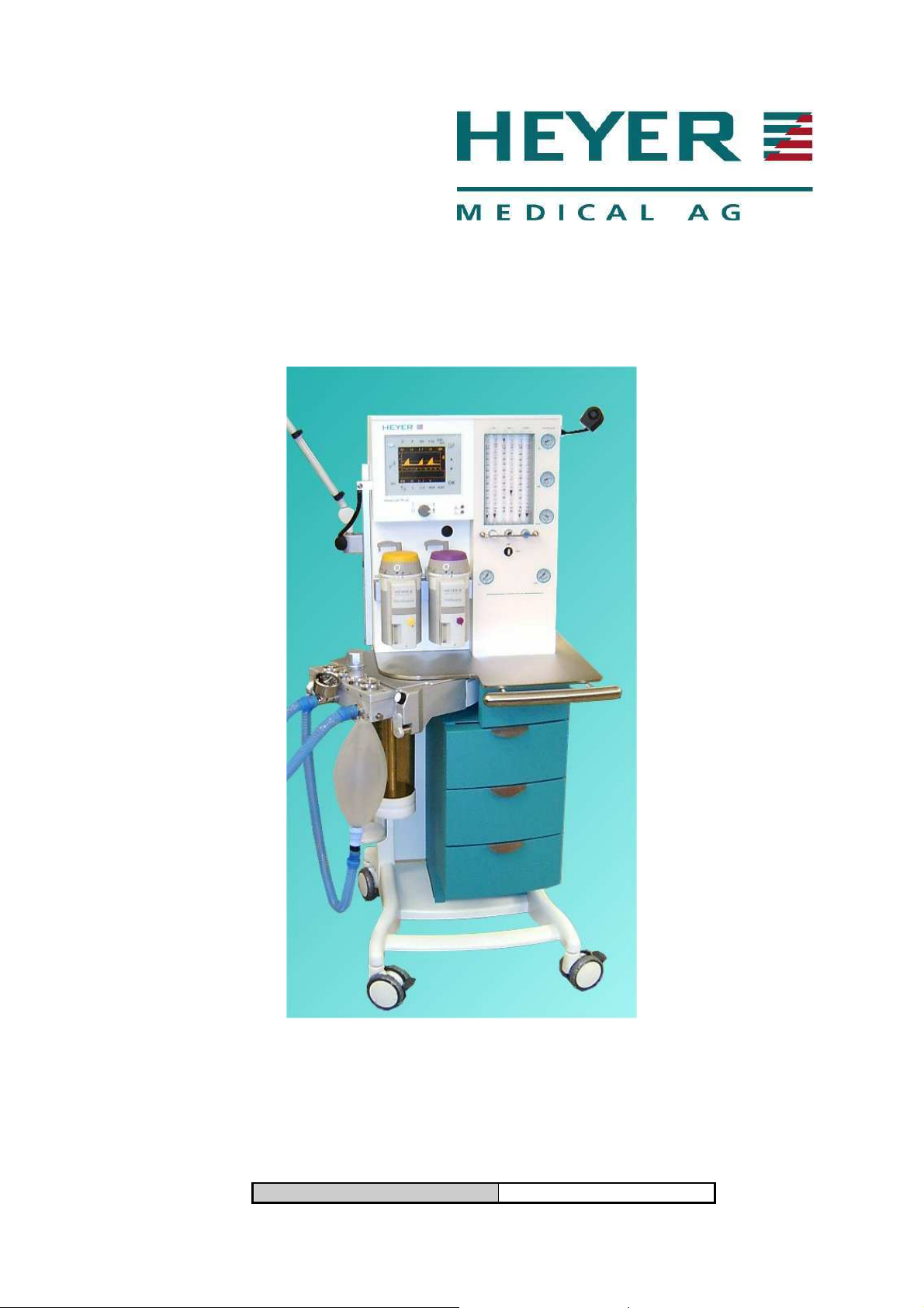
2.8 Electrical supply
The line cord of the Modular+ is connected to an internal terminal block. Directly connected to this
terminal are convenience receptacles and the unit itself. Line supply to the receptacles is available
with the line cord connected. Line supply for the unit is switched by the main switch at the right side of
the unit. The two pole switched power supply is protected by each one 5A circuit breaker. The
switched line supply is connected to the AC IN connector on power supply board AVM 2-1. Another
third pole of the main switch is connected via the terminal to the board AVM 2-1 (X5:5,6), enabling to
detect a main switch OFF position or missing line supply.
Line cord
N 120/230 V
L 120/230 V
X5 pin 6
PE
X5 pin 5
X5 pin 4
X5 pin 3
power supply board
int. ground
wiring
Circuit breakers
ventilator
Main switch
Power
supply board
5 A
1
8
1 1
1
1
2
2
2
2
2
3
4
7
3
3 4
4
5
6
6
5
Circuit breaker
5 A
battery
Convenience
Fig. 1 Line Terminal Block, 120/230VAC Supply
The 120 V configuration has
additional circuit breakers
15
Page 16
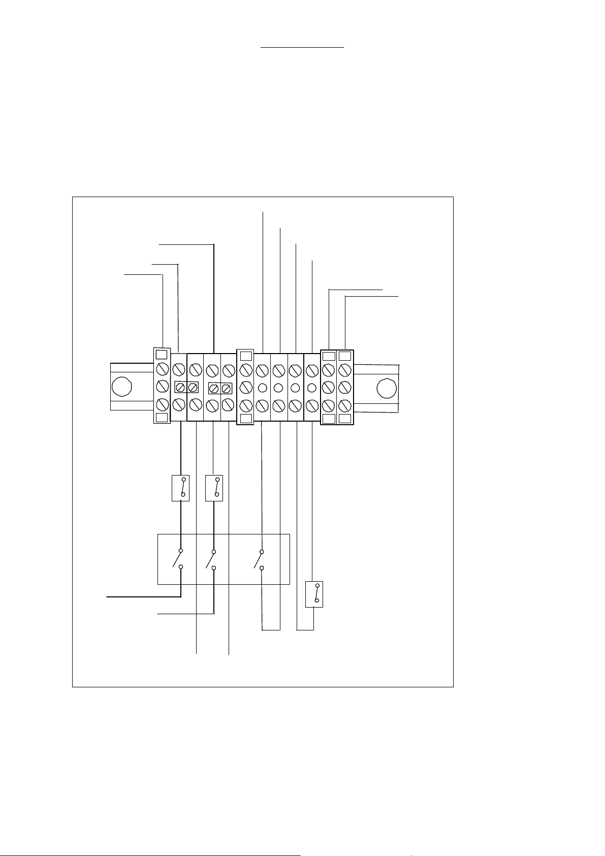
2.8.1 Electrical components
RS 232
interface
Option 1
RS 232
interface
Option 2
Repair Information
RS 232
interface
module 1
flow meter
backlight
transformer
battery
motor
power supply
module 1
Communication
RS 232
interface
Display
Controller
module 1
Display
module 1
main
switch
module 2
AVM 3-1
Supervisor
Touch Screen
PT 100
heat
blanket
I²C
fan
oxygen
sensor
proportional
valve
Fig. 2 Overview electrical components
interface
P2
module 2
AVM 3-2
Ventilation
solenoid valve
P1
ext. flow
sensor
int. flow
sensor
16
Page 17
Repair Information
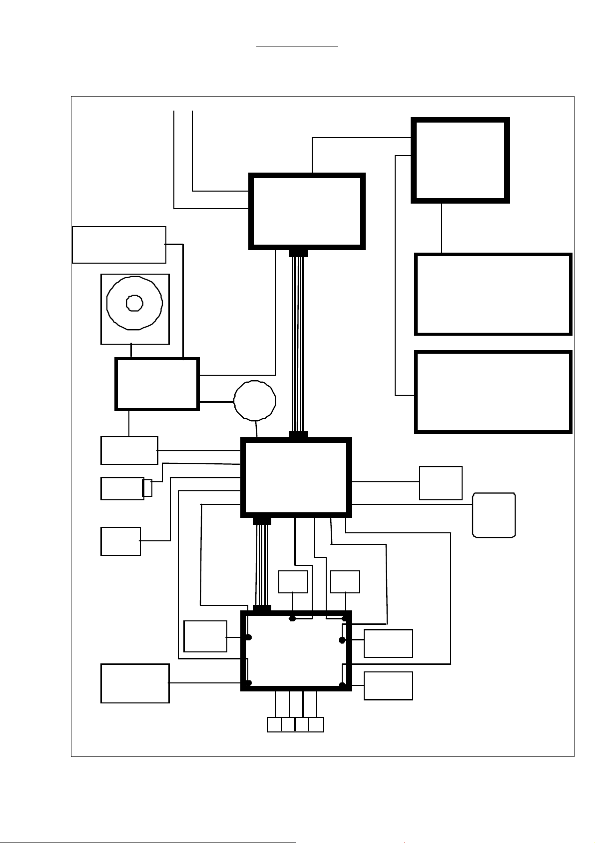
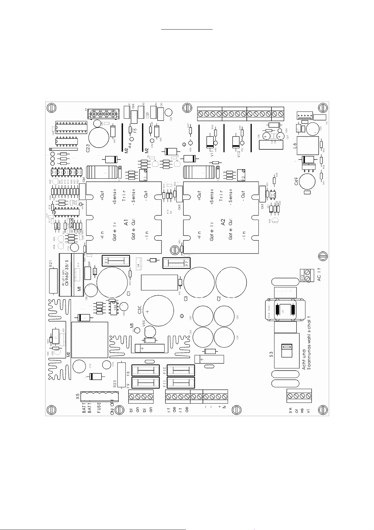
2.9 Power supply module
The power supply module is located in the frame behind the drawers. This module serves for the
voltage supply of the ventilator modules 1 and 2, the flow meter block illumination, the patient circuit
heating blanket and the charging / discharging control for the battery. The power supply board allows
the supply with either 230VAC or 115VAC, the supply voltage can be selected with a switch on the
power supply board.
Fig. 3 Power supply module
17
Page 18

Repair Information
2.9.1 Connectors on power supply board AVM 2-1
Connector connected to Pin. def. Func. / Signal Color / No.
X1 Module 1 X1-1 +5V yellow
X1-2 GND red
X1-3 GND green
X1-4 +12V blue
Connector connected to Pin. def. Func. / Signal Color / No.
X2 X2-1 +5V
X2-2 GND
X2-3 GND
X2-4 +12V
Connector connected to Pin. def. Func. / Signal Color / No.
X3 X2-1 -
X2-2 -
X2-3 GND
X2-4 +12V
Connector connected to Pin. def. Func. / Signal Color / No.
X4 X4-1 +5V
X4-2 GND
X4-3 GND
X4-4 +12V
Connector connected to Pin. def. Func. / Signal Color / No.
X5 Battery, X5-1 BATT+ brown
Fuse for Battery X5-2 BATT- black
Main switch X5-3 Cir.break. bat. black 6
X5-4 Cir.break. bat. black 5
X5-5 Main switch black 4
X5-6 Main switch. black 3
Connector connected to Pin. def. Func. / Signal Color wire isolat.
X6 Transformer X6-1 sec.IIa 15VAC blue
RT110/12 secondary X6-2 sec IIa green
X6-3 sec. IIb 15VAC blue
X6-4 sec IIb green
Connector connected to Pin. def. Func. / Signal Color wire isolat.
X7 Transformer X7-1 prim.I, L120/230V
RT110/12 primary X7-2 prim.I, N120/230V
X7-3 prim.II,L120/230V
X7-4 prim. II, . violet
Connector connected to Pin. def. Func. / Signal Col. wire isolat.
X11 Transformer X11-1 Sec.Ia 22VAC red
RT110/22 secondary X11-2 Sec Ia yellow
X11-3 Sec. Ib 22VAC red
X11-4 Sec Ib yellow
AC
AC
AC
black/
orange
white
18
Page 19

Repair Information
Connector connected to Pin. def. Func. / Signal Color / No.
X12 int. connection X12-1 AC, N 110V/230V blue
AC IN terminal X12-2 AC , L 110V/230V black
Connector connected to Pin. def. Func. / Signal Color / No.
X13 Module 2 X13-1 +12V red
Board X13-2 GND blue
AVM 3-2 X13-3 +5V(1) red
X13-4 GND blue
Connector connected to Pin. def. Func. / Signal Color / No.
X14 Module 2 X14-1 +5V(2) red
Board X14-2 GND blue
AVM 3-2 X14-3 -12V red
X14-4 GND blue
Connector connected to Pin. def. Func. / Signal Color / No.
X15 Module 2 X15-1 Control Sign. white
Board X15-2 Control Sign. white
AVM 3-2 X15-3 Control Sign. white
X15-4 Control Sign. white
Connector connected to Pin. def. Func. / Signal Color / No.
X16 Module 2 X16-1 GND blue
AVM 3-2 X16-2 +31V red
Connector connected to Pin. def. Func. / Signal Color / No.
X17 solid state relay X17-1 22VAC to heat. bl. black
heating blanket X17-2 22VAC to relay black
X17-3 + Control voltage black
X17-4 GND black
Connector connected to Pin. def. Func. / Signal Color / No.
X22 DC-AC convert. X22-1 +supply voltage red
for flow meter X22-2 -
illumination X22-3 -
X22-4 GND black
2.9.2 Fuses on power supply board AVM 2-1
Fuse No. Fuse value Fuse protects
F1 4 A MT, medium slow-blow DC / DC-converter +5V
F7 8 A M, medium -blow DC / DC-converter +12V
F8 8 A M, medium -blow Transformer, Sec. IIa
F9 8 A M, medium -blow Transformer, Sec. IIb
F10 10 A T, slow-blow Transformer, Sec. Ia
F11 10 A T, slow-blow Transformer, Sec. Ib
19
Page 20

Repair Information
2.9.3 Charging / discharging control for the battery:
The charging / discharging control for the battery is also located on the power supply board AVM 2-1.
Status indicators as red, green and yellow LEDs are located on the board to show functions like check
or charging of the battery.
2.9.4 Status Indicators Of Battery Control:
LED LED light Battery status
LED yellow (V28) continuous charging
LED yellow (V28) flashing check
LED green (V37) continuous fully charged
LED red (V38) flashing or continuous. defect
20
Page 21
Repair Information
2.10 Module 1
Ventilator module 1 consists of two processor boards. This module serves for the operation of touch
screen interface with different menus displayed on the display.
All safety functions, e.g. the complete ventilator control, are located on ventilator module 2. Module 1
is connected to module 2 by means of an RS 232C- interface. Module 1 serves to give the functions
for parameter and alarm settings to module 2. Module 2 sends the measured parameters or generated
alarm signals to module 1 to display.
Fig. 4 Module 1 PC board
21
Page 22

Repair Information
2.10.1 Connectors on module 1
Connector connected to Plug conf. Func. / Signal
X4 Module 2 10 pole communication
with module 2
Connector connected to Plug conf. Func. / Signal
X5 EL Display 20 pole Connected to the
display
Connector connected to Plug conf. Func. / Signal
X6 Power supply 4 pole Power suppy
Connector connected to Plug conf. Func. / Signal
X7 Touch screen 32 pole communication
with touch screen
Connector connected to Plug conf. Func. / Signal
X8 Module 2 14 pole communication
with module 2
Connector connected to Plug conf. Func. / Signal
X9 Module 2 28 pole communication
with module 2
Connector connected to Plug conf. Func. / Signal
X10 Selector switch 14 pole communication
With the selector
switch
Connector connected to Plug conf. Func. / Signal
X19 LCD Display Flat cable
connector
Connector connected to Plug conf. Func. / Signal
X20
(on the
backside)
Display
illumination
4 pole Power supply
Connected to the
display
display
illumination
22
Page 23
Repair Information
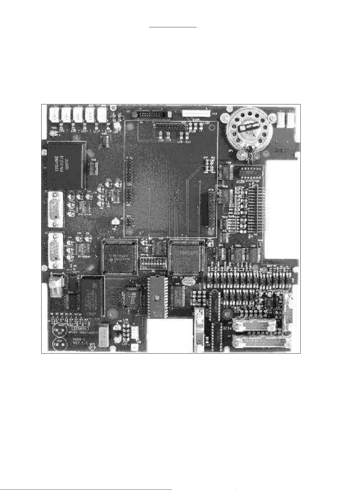
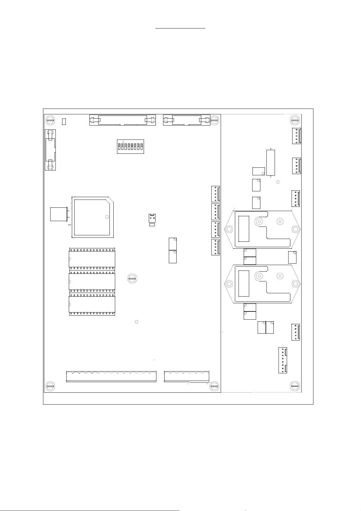
2.11 Ventilator Module 2, AVM 3-1 and AVM 3-2
Ventilator module 2 serves for the active ventilator control. Module 2 consists of two CPU boards, the
CPU board AVM3-1 with µP1 serves for a continuous validation of control actions generated by CPU
board AVM3-2 and for the communication between module 2 and module 1.
The CPU board AVM3-2 with µP2 generates all active control signals, after a validation of these
signals by µP1, AVM3-2 is enabled to operate the different active elements like the solenoid vales and
proportional valve.
Keyboard Alarm Panel
RS232
X4
P1
P2
X3X2
CPU-board
IF
EF
1
O2
1
P9
PV
1
X8
X9
X10
X11
AVM 3-2
P3
P5
1
1
1
1
P6
P1
P8
P7
P1
P1
P11
P10
R33
Pressure
Sensor #2
Pressure
Sensor #1
P2P1
X5
1
X7
GND
X1
X8
P2
P2
P2
X3
X1
1
7
23
456
8
MD
1
ON
CPU-board
AVM 3-1
X13
X7
1
GND
Q1
V29
V30
V38
V19
AVM 3-1
Software
+12 GND
GND
+5(1)
1
X15
GND
GND
+5(2)
Power Supply
-12
Fig. 5 View on module 2
DIS/AC
HTON
M
BATT
+31
1
X16
swrtrs wsswge
Motor
(-) (+) -> lösen
Endsch.
Start
X11
1
gn
23
Page 24
Repair Information
2.11.1 Parts list module 2
Pos. No. Description Order No.
1 Ventilator module 2, complete 460-1150
2.11.2 Connectors on module 2
2.11.2.1 Plug connectors on board AVM 3-1
Connector connected to Plug conf. Func. / Signal
X2 Module 1 28 pole communication
with module 1
Connector connected to Plug conf. Func. / Signal
X3 Module 1 14 pole communication
with module 1
Connector connected to Plug conf. Func. / Signal
X4 Module 1 10 pole communication
with module 1
Connector connected to Pin. def. Func. / Signal Color / No.
X7 PT-100 sensor X7-1 temperature dep. blue
X7-2 resistance red
Connector connected to Pin. def. Func. / Signal Color / No.
X9 Fan ventilator X9-1 +12V red
FAN pneumatic X9-2 fan control signal yellow
module X9-3 n.c.
X9-4 n.c.
X9-5 GND black
Connector connected to Pin. def. Func. / Signal Color / No.
X10 Driving gas X10-1 +12V white
Driving gas switch switch to detect X10-2 GND brown
a failure of the gas X10-3 n.c.
supply X10-4 n.c.
X10-5 n.c.
Connector connected to Pin. def. Func. / Signal Color / No.
X11 over temperature X11-1 22VAC when red
HTSEC switch (NC) X11-2 switch is open blue
patient X11-3 n.c.
block heating X11-4 n.c.
X11-5 n.c.
24
Page 25

Repair Information
2.11.2.2 Plug connectors on board AVM3-2
Connector connected to Pin. def. Func. / Signal Color / No.
X5 internal X5-1 signal (+1-5 V) orange
IF flow sensor X5-2 +10V mint
X5-3 GND. violet
X5-4 n. c.
X5-5 n. c.
Connector connected to Pin. def. Func. / Signal Color / No.
X7 external X7-1 flow dep. signal. red
EF flow sensor X7-2 n.c.
X7-3 n.c.
X7-4 n.c.
X7-5 flow dep. signal. blue
Connector connected to Pin. def. Func. / Signal Color / No.
X8 Oxygen cell X8-1 n. c.
O2 X8-2 + voltage fuel cell red
X8-3 - voltage fuel cell blue
X8-4 n.c.
X8-5 n.c.
Connector connected to Pin. def. Func. / Signal Color / No.
X3 proportional X3-1 + 12V blue
PV valve X3-2 n. c.
X3-3 control volt. 0-5V gray
X3-4 n.c.
X3-5 GND green
Connector connected to Pin. def. Func. / Signal Color / No.
X11 solenoid X11-1 GND ( MV4) brown / 1
valve X11-2 + 10V (MV4) red / 2
block X11-3 GND (MV3) orange / 3
X11-4 + 10V (MV3) yellow / 4
X11-5 GND (MV1) green /5
X11-6 + 10V (MV1) blue / 6
X11-7 GND (MV2) violet / 7
X11-8 + 10V (MV2) gray / 8
2.12 Display
The display of the ventilator is a LCD or EL type. It is connected to the module 1.
2.13 Battery
The battery is a maintenance free seal lead acid type. The recharging time is a maximum of 7 hours
with a fully depleted battery. The backup time is about 30 minutes with a fully charged battery. To
prevent unintended loss of battery operation, it is recommended to replace it with a new HEYER
battery every 3 years.
25
Page 26
2.14 Ventilator pneumatic
Repair Information
Fig. 6 Ventilator pneumatic
26
Page 27

Repair Information
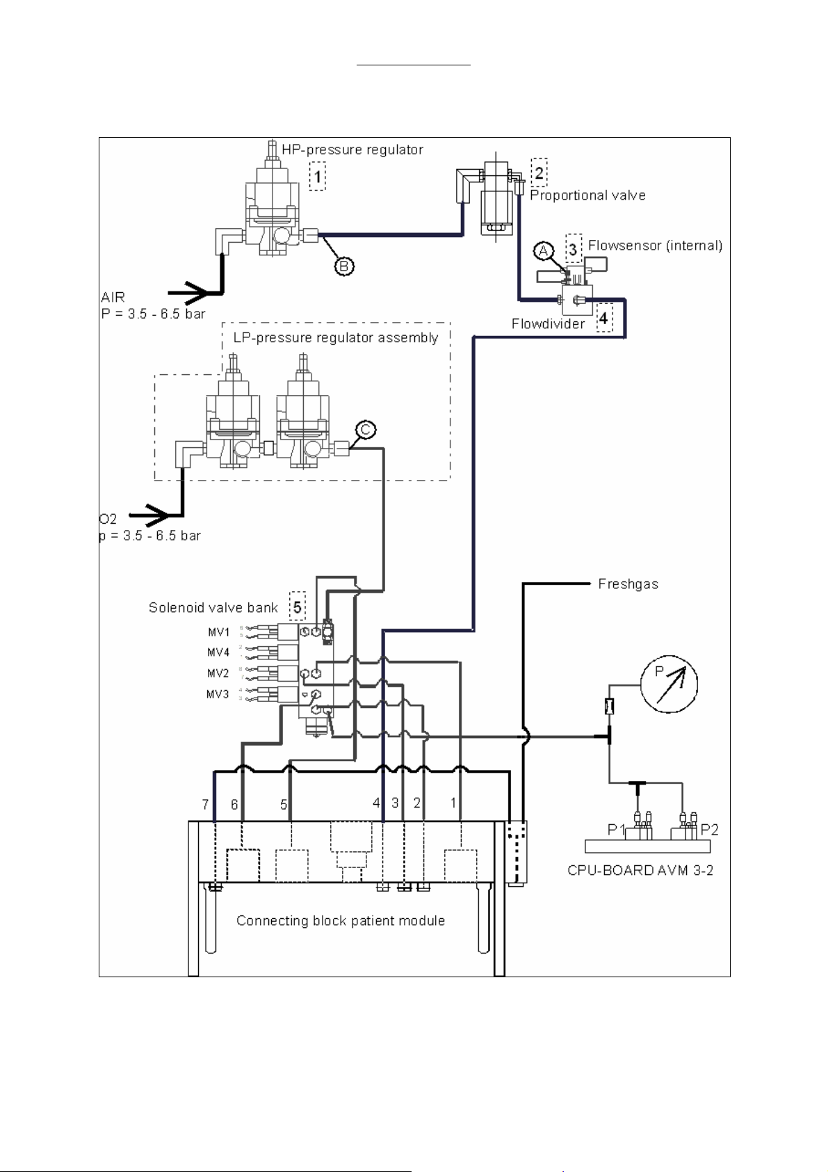
2.14.1 Ventilator pneumatic drive
Air or Oxygen, in the CMV mode, serves as driving gas for the ventilator. In addition to the flow meter
block, a pressure reducer, reducing the supply pressure to 200 kPa (2 bar; 29 PSI), is supplied by the
Air or oxygen connection. This pressure represents the high system pressure of the ventilator. The
pressure reducer is named HP pressure reducer.
The HP pressure reducer is placed ahead of the proportional valve that generates the driving gas flow
during the inspiratory phase. This flow is led through the flow divider and fills the bellows dome that
surrounds the silicone bellow.
In response to the inspiratory and expiratory phases of a respiration cycle, the pneumatic valves
(diaphragm valves) of the patient module are activated by solenoid valves.
These solenoid valves, MV1, MV3, and MV2 are supplied by a second pressure reducer assembly
(LP- double stage pressure reducer) at the low system pressure, together with MV4, with about 20 kPa
(200 mbar; 2.9 PSI)// 25 kPa (250 mbar; 3,63PSI).
Cyclic activation of the proportional valve and solenoid valves is steered by the processors of module
2 according to the parameters set on the control panel of the ventilator.
A description of the individual components will be found in the following chapters:
2.14.2 HP pressure reducer
The HP pressure reducer serves for a stabilization of the supply pressure for the proportional valve.
The flow generated by the proportional valve thus becomes independent of pressure variations.
The setting of the HP pressure reducer (200 kPa (2 bar; 29 PSI)) at the same time determines the
maximum inspiratory flow of 75 +0/-4 L/min with respect to the respirator.
2.14.3 LP- double stage pressure reducer
This pressure reducer assembly is supplied with oxygen in parallel to the measuring tube block or ratio
system, respectively. It reduces the input pressure to 20 kPa (200 mbar; 2.9 PSI)// 25 kPa (250 mbar;
3,63PSI), and is connected to the solenoid valve bank.
2.14.4 Solenoid valves MV1 to MV4
The solenoid valves MV1, MV2, MV3 and MV4 are mounted on a bank behind the patient module
docking station to which the tubes to the docking station of the patient module and the LP- double
stage pressure reducer are connected.
MV1: This solenoid valve activates, in the CMV mode, the valve for closing the outlet of the bellows
dome (bellows control valve) through the line 5, when driving gas flows in for inspiration. It is supplied
by the LP- double stage pressure reducer.
MV2: This solenoid valve activates, in the CMV mode, the valve closing the expiratory channel of the
patient module (expiratory valve), via MV2 through the line 1. It is supplied by the LP- double stage
pressure reducer via MV4.
MV3: This solenoid valve activates, in the CMV mode, the valve for the fresh gas decoupling
(decoupling valve) through the line 6. It is supplied by the LP- double stage pressure reducer.
MV4: This solenoid valve is used for internal supply of MV2 with pressure of the LP- reducer.
27
Page 28

Repair Information
2.14.5 Pneumatic driving module
The driving module consists of the proportional valve and flow divider with an internal flow sensor. The
proportional valve supplied by the HP pressure reducer generates a driving gas flow of 0-75 l/min in
relation to the control voltage of the proportional valve of 0 - 5VDC.
The control voltage of the PV, required for the pre-selected parameter settings, is generated by the
CPU board AVM 3-2.
The driving gas flow Q
Q
drive gas
VT = generated tidal volume
Ti = Inspiratory time
= VT/Ti with Q
drive gas
is in the following in relationship with the tidal volume:
drive gas
= driving gas flow
2.14.6 Flow metering module
The flow metering module attached to the proportional valve consists of a flow sensor with a
measuring range of 0 - 1 l/min and a flow divider. The flow divider splits the total flow in a ratio of 79: 1,
and the bypass flow is lead to the flow sensor. A closed loop that allows high accuracy and back up in
the generation of the tidal volume results from this configuration via the module 2 CPU-boards.
2.14.7 Tube color coding
Despite the local color coding system, all the pneumatic tubes inside the apparatus will be according
to the coding label inside the unit, if it is not according to the local color coding system, next to the flow
meter block. Typically it will be according to one of the follow standards.
Gas ISO 32 Standard US standard
O2 White Green
N2O Blue Blue
AIR Black/White Yellow
On the outside of the apparatus, the coding will be as ordered.
28
Page 29
Repair Information
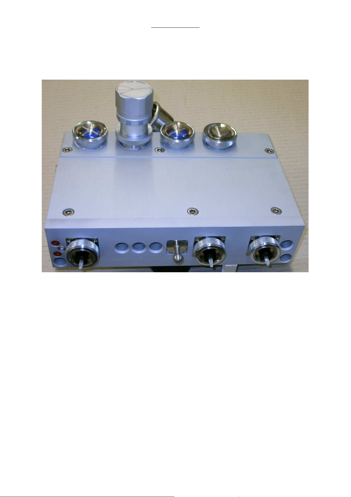
2.15 The patient module (circle system)
2.15.1 Top and back side view on the patient module
1 2 3 4
6
5 12 15
8 9 10 11 13 14
7 7
Fig. 7 Top and backside view on the patient module
Pos. Description
1. Expiratory valve (passive)
2. Airway pressure limiting valve (APL)
3. Inspiratory valve (passive)
4. Room air valve, emergency air valve
5. Connector of expiratory flow sensor
6. Connectors of power supply heating blanket
7. Bores for guiding pins of connecting block
8. Expiratory valve (active)
9. Port for pressure measurement
10. Port for expiratory valve activation in the manual mode
11. Port for driving gas
12. Locking bolt
13. Bellows diaphragm valve
14. Decoupling diaphragm valve
15. Port for fresh gas
29
Page 30
Repair Information
1 2
3
4
5
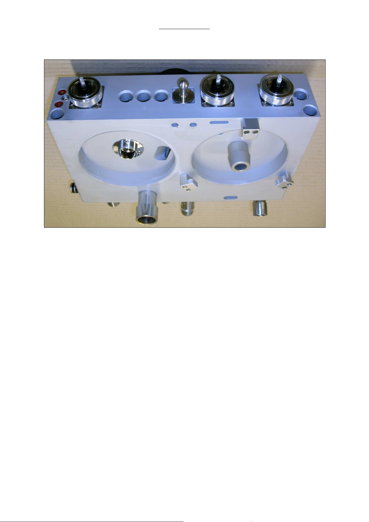
2.15.2 Bottom and back side view on the patient module
6
7
8
Fig. 8 Bottom and backside view on the patient module
Pos. Description
1
2
3
4
5
6
7
8
Fixing screws for locking bolt
Exhaust for driving gas
Driving gas in- and outlet to bellows dome
Thread for CO2 absorber canister fixing, outlet from patient module to absorber
Inlet for re-breathing gas from absorber to patient module
Connector for bellows
Inlet for ambient air valve / emergency air valve
Port for anesthetic gas scavenging tube (30 mm cone)
30
Page 31

Repair Information
2.15.3 Functional representations of the patient module
gasmonitoring
2
V
5
3
41
6
11
7
8
9
10
Fig. 9 Survey of the patient module
Pos. Description
1
2
3
4
5
6
7
8
9
10
11
12
13
14
15
16
17
18
19
Patient's y-piece
Side stream gas monitor
Inspiratory bacterial filter
Expiratory bacterial filter
Airway pressure monitor connection
Inspiratory valve (passive)
Expiratory valve (passive)
Spirometry sensor
Airway pressure limiting valve (APL)
Waste gas outlet
Expiratory valve
Room air valve, emergency air valve
Ventilator control pneumatic
CO2 absorber
Bellows
Decoupling valve
Bellows dome
Bellows valve
Reservoir / manual ventilation bag
P
12
13
14
16
15
17
18
V
19
31
Page 32

2.15.3.1 CMV mode, inspiration
gas monitoring
Repair Information
P
expiratory valve
V
V
is > 2 mbar
MV3 ="1"
MV2 ="1"
decoupling valve
bellows valvewhen reservoir pressure
Fig. 10 Survey of the patient module, CMV mode, inspiration
MV4 ="1"
MV1 ="1"
32
Page 33

2.15.3.2 CMV mode, expiration
gas monitoring
Repair Information
expiratory valve
V
when reservoir pressure
is > 2 mbar
P
V
MV3 ="0"
MV2 ="0"
MV4 ="0"
decoupling valve
bellows valve
Fig. 11 Survey of the patient module, CMV mode, expiration
MV1 ="0"
33
Page 34

2.15.3.3 Manual mode, inspiration
gas monitoring
Repair Information
P
expiratory valve
V
when the set respiratory
pressure is attained
V
MV3 ="0"
MV2 ="0"
MV4 ="0"
MV1 ="0"
Fig. 12 Survey of the patient module, Manual mode, inspiration
decoupling valve
bellows valve
34
Page 35

2.15.3.4 Manual mode, expiration
gas monitoring
expiratory valve
Repair Information
decoupling valve
V
MV3 ="0"
MV2 ="0"
MV4 ="0"
MV1 ="0"
Fig. 13 Survey of the patient module, Manual mode, expiration
bellows valve
35
Page 36

Repair Information
2.15.3.5 Spontaneous mode, inspiration
gas monitoring
P
emergency air valve opens
at p < - 3 mbar
expiratory valve
V
decoupling valve
when reservoir pressure
is > 2 mbar
V
MV3 ="0"
MV2 ="0"
MV4 ="0"
MV1 ="0"
Fig. 14 Survey of the patient module, Spontaneous mode, inspiration
bellows valve
36
Page 37

Repair Information
2.15.3.6 Spontaneous mode, expiration
gas monitoring
P
expiratory valve
V
decoupling valve
waste gas
V
MV3 ="0"
MV2 ="0"
MV4 ="0"
MV1 ="0"
Fig. 15 Survey of the patient module, Spontaneous mode, expiration
bellows valve
37
Page 38

Repair Information
2.15.4 Components of the patient module
2.15.4.1 Ventilation bellows system
The ventilator’s driving system can be characterized as a constant flow generator. The driving gas of
this generator fills the bellows dome to compress the bellows. The breathing gas is pressed out of the
bellows into the circuit. Due to the weight of the descending bellows, it is self-filling when the driving
gas flow is stopped. The bellows control valve enables the escape of the driving gas.
2.15.4.2 Manual Respiration Bag / Reservoir
In the manual mode this device acts as a normal breathing bag, enabling the user to ventilate the
patient manually. In CMV mode this bag acts as a reservoir for fresh gas in the inspiration phase. In
the expiratory phase the re-breathing gas and the fresh gas are accumulated in this reservoir. The
bag’s in- and deflation corresponds to the volume balance of the breathing circuit and the patient.
When a volume loss occurs, the bag deflates breath by breath and finally collapses. Such a collapsing
breathing bag is an indicator for a leakage. The breathing bag must collapse if the fresh gas flow,
reduced by the patient’s uptake, is not able to compensate the leakage.
2.15.4.3 CO2 absorber
The soda lime inside the absorber retains the carbon dioxide from the re-breathing gas. The flow
orientation is upstream.
2.15.4.4 Inspiratory and expiratory valves
To ensure the gas flow direction the two one-way-valves in the inspiratory limb and expiratory limb are
integrated inside the patient module. These valves are seen activating form the top of the module.
2.15.4.5 Airway pressure relief valve
In CMV position the APL valve closes the re-breathing system towards the scavenging line and limits
the reservoir pressure to a constant value of 2 cmH2O. In manual mode the APL valve acts as a
normal spring loaded pressure relief valve, limiting the maximum pressure in the re-breathing system.
2.15.4.6 Room Air valve
Due to the tendency of the descending bellows to refill itself by creating a negative pressure inside the
bellows this valve prevents the patient from becoming any negative pressure by opening the
diaphragm and allowing ambient air to refill the bellows.
2.15.4.7 Diaphragm/Membrane valves
Inside the patient module valves operate the expiratory line, the bellows dome outlet and the fresh gas
decoupling line during the CMV-mode. These valves are controlled by pressured gas to open or close
the valve’s path. All valves are open when not inflated. The power gas for these valves is controlled by
the ventilator’s valve bank using a supply pressure of about 20 kPa (200 mbar; 2.9 PSI)// 25 kPa (250
mbar; 3,63PSI) from the ventilator pneumatic.
38
Page 39

Repair Information
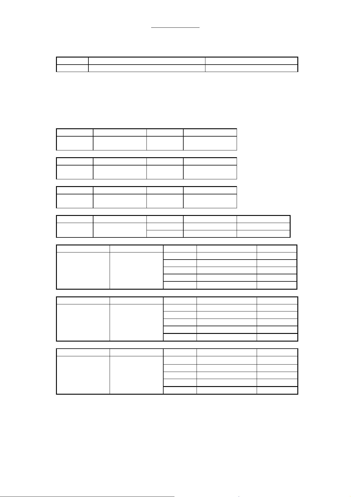
2.15.2.7.1 Status of the diaphragm/membrane valves:
The diaphragm valves are pneumatically operated by solenoid valves. The following list shows the
correspondence between diaphragm valve, solenoid valve and pressure port.
Valve Bellows valve Exp. valve Decoupling valve
controlled by MV 1 MV 2 MV 4 MV 3
connected to port # 5 1 3 6
wire # 5, 6 7, 8 1, 2 3, 4
In the following the status of the diaphragm/membrane valves are shown corresponding to the
selected ventilation mode of the ventilator.
2.15.2.7.2 Machine OFF or Ventilator In Standby
Valve MV 1 MV 2 MV 3 MV 4
Activity OFF OFF OFF OFF
Pressure on port 5, No 1, No 6, No no sup. of MV2
2.15.2.7.3 Manual / Spontaneous Mode, INSPIRATION and EXPIRATION
Valve MV 1 MV 2 MV 3 MV 4
Activity OFF OFF OFF OFF
Pressure on port 5, No 1, No 6, No no sup. of MV 2
2.15.2.7.4 CMV Child / Adult Mode, INSPIRATION
Valve MV 1 MV 2 MV 3 MV 4
Activity ON ON ON ON
Pressure on port 5, Yes 1, Yes 6, Yes supply of MV 2
2.15.2.7.5 CMV Child / Adult, EXPIRATION
Valve MV 1 MV 2 MV 3 MV 4
Activity OFF OFF OFF OFF
Pressure on port 5, No 1, No 6, No no sup. of MV 2
2.15.2.7.6 CMV Adult, EXPIRATION and PEEP
Valve MV 1 MV2 MV3 MV4
Activity OFF ON OFF ON
Pressure on port 5, No 1, Yes 6, No supply of MV2
39
Page 40

Repair Information
2.15.2.7.7 Compliance Test Patient Module
The compliance test patient module is divided in 3 phases.
Phase 1. Flow into the re-breathing system and test of flow sensors.
Valve MV 1 MV2 MV3 MV4
Activity ON OFF ON ON
Pressure on port 5, Yes 1, No 6, Yes no sup. of MV2
Phase 2. Pressure increase up to test pressure 40 cmH2O, calculation of system compliance.
Valve MV 1 MV2 MV3 MV4
Activity ON ON ON ON
Pressure on port 5, Yes 1, Yes 6, Yes supply of MV2
Phase 3. Test of pressure loss.
Valve MV 1 MV2 MV3 MV4
Activity ON ON ON ON
Pressure on port 5, Yes 1, Yes 6, Yes supply of MV2
2.15.2.7.8 Leak Test Patient Module and Fresh Gas Module
Valve MV 1 MV2 MV3 MV4
Activity ON OFF OFF OFF
Pressure on port 5, Yes 1, No 6, No no sup. of MV2
40
Page 41

Maintenance and Calibration
3 Repair Information
3.1 Introduction
This chapter of the service manual provides the necessary technical information to perform repairs to
the instrument. The most important perquisites for effective troubleshooting are a trough
understanding of the instruments functions, as well as understanding the principals of operation.
3.2 Warnings and precautions
In the event the instrument covers are removed, observe the following warnings and guidelines
3.2.1 Precautions
1. Do not short components leads together
2. The instrument covers must not be removed by anyone other than qualified technical personnel
who have received supplementary instructions regarding maintenance of medical equipment
and/or have equivalent experience in this area.
3.2.2 Warnings
1. This device operates using compressed gas at high pressures. When attaching emergency gas
tanks, always open tank valves slowly, watching the cylinder gauge indicate the tank pressure.
When disconnecting the tanks, always close the valves slowly. Use the Modular+ flow meters to
bleed down the pressure, watching the cylinder gauge indicating the depleting tank pressure,
before disconnecting the tank from the yoke. Always open and close tank valves fully.
2. This device operates using compressed gas at high pressures from the hospital central supply.
When connecting gas supply lines, attach the hose connection to the machine before connecting
the quick disconnect fitting to the hospital source. Disconnect the supply hose from the hospital
source connection prior to disconnecting it from the Modular+ gas connection fittings.
3. Whenever flowing anesthetic gases, nitrous oxide, oxygen, or any hospital gas always use the
appropriate agent evacuation system.
4. Never oil or grease any oxygen equipment unless the lubricant used is made and approved for
this kind of service. In general, oils and greases oxidize readily, and in the presence of oxygen
burn violently.
Page 42

Maintenance and Calibration
3.3 Troubleshooting Guidelines
1. Identify the problem – Due to the wide variety of potential symptoms, certain problems may be
more subtle than others. Following the guidelines of the tests will help determine the problem if
one exists.
2. Avoid shorting component leads together – During repair procedures, it can be tempting to
make a quick series of measurements. Always turn the power off before connecting and
disconnecting the test leads and probes. The accidental shorting of leads can easily stress the
components and cause a second failure (aside from the safety risk).
3. Use the proper equipment – The equipment listed below is suggested to fulfill a wide range of
troubleshooting requirements. It is imperative to use the designated equipment in order to ensure
proper results of any and all test procedures.
4. Clean up the repair area – After any repair, clean off the repair area.
3.4 Troubleshooting Charts
3.4.1 Error Messages during ventilation
Display message Cause Corrective action User
Vent Error:
Use Manual Ventilation
Call Service
CPU Error: Use Manual
Ventilation
Call Service
Set APL valve to
CMV/SP position
Flow Error: Use Manual
Ventilation
Call Service
Valve Error:
Use Manual Ventilation
Call Service
No communication between
AVM 3-1 and AVM 3-2
(ventilator microprocessor
boards) for more than 8 sec.
No communication
between AVM 3-1 and module
1 (user interface) for more than
20 sec.
System Failure (Module 1)
Watchdog Error (Module
2)
AVM3-2
PPEAK is greater than 10 mbar
and lowest expiration pressure
after the expiration still greater
than PPEAK–2mbar
No pressure relief in the
expiration
CMV, PCV
After the first five breaths in
CHILD resp. after the first three
breaths ADULT: Last
inspiratory flow is lower than
0,05 L/min, even though more
than 2.00 L/min were set at the
prop. valve
Sensor does not deliver any
values
AVM3-2 CMV
The internal actual flow value is
measured during the inspiration
and may not exceed the
following desired value x factor
1.5:
AVM3-2 PCV
The same as CMV, but other
tolerance
Prop. Valve faulty
Finish the case with manual
ventilation;
Take the machine out of use;
Call Service
Finish the case with manual
ventilation;
Take the machine out of use;
Call Service
Set APL to the CMV/SP
position
Reset automatically after
pressure relief, Restart of the
ventilation after request.
Finish the case with manual
ventilation;
Take the machine out of use;
Call Service
The intermitting tone is reset via
the mute button
(acknowledgement)
Reset the error message via
the compliance test
Corrective action
Service technician
Exchange module 2 (ventilator
microprocessor boards)
Exchange either the module 2,
the module 1 or the
communication cable
connecting the two modules
If resetting the APL valve does
not solve the problem, check
the correct functions of the APL
valve, solenoid valves and the
diaphragm valves
Recalibrate the proportional
valve, internal flow sensor and
the characteristic of the
proportional valve. If that does
not solve the problem,
exchange the
1. proportional valve
2. internal flow sensor
Recalibrate the proportional
valve, internal flow sensor and
the characteristic of the
proportional valve. If that does
not solve the problem,
exchange the
1. proportional valve
2. internal flow sensor
42
Page 43

Maintenance and Calibration
Display message Cause Corrective action User
Valve Error: Use Manual
Ventilation
Call Service
Calibrate Breathing
System
Perform Compliance Test
when convenient
Pressure Reading out of
tolerance
Perform Compliance Test
when convenient
No drive gas; please
check
Flow/Volume Readings
not available
Replace Flow Sensor –
Call Service
A P N E A
Breathing Circuit
Disconnect
PEEP greater than Pmin
FiO2 lower than FiO2
min
Tidal Volume lower than
VTE
Peak pressure greater
than alarm limit
Peak pressure below
alarm limit
Minute Volume below
alarm limit
PEEP greater than
PEEP-Setting
FiO2 greater than FiO2
alarm limit
Check Vent Dial position
AVM3-2 CMV/ PCV
The actual internal flow value
should be 0 during expiration
AVM3-2 CMV, PCV
Difference between the set and
the detected state of each
solenoid valve for more than
200 ms
AVM3-1, AVM3-2
A difference between the two
pressure sensors of more than
10 mbar
AVM3-1
Monitoring of the pressure
switch for the driving gas
AVM3-1 during ventilation
External flow sensor is broken
or short-circuited
AVM3-1. Manual/ spontaneous
Within a period of 15 to 60
seconds a expiration cannot be
detected
AVM3-1 CMV, (S)CMV, PCV
The peak pressure PPEAK is
lower than 0.5 mbar and lower
then the set pressure limit Pmin
AVM3-1 CMV, (S)CMV, PCV
The end expiratory pressure is
greater than the set pressure
limit Pmin
AVM3-1
The measured O2 value is
lower than the set O2min limit
AVM3-1
The measured VTE value is
lower than the set VTEmin limit
AVM3-1
The measured Ppeak value is
greater than or equal to the set
Pmax limit
AVM3-1
The measured Ppeak value is
lower than the set Pmin limit
AVM3-1
The calculated M.Vol value is
lower than the set M.Vol min
limit
AVM3-1
The measured PEEP value is 5
mbar higher than the set PEEP
AVM3-1
The measured FiO2 value is
greater than the set FiO2max
limit
AVM3-1
The selector switch position is
monitored An invalid position
must be eliminated within two
seconds. After this the alarm
message appears.
Finish the case with manual
ventilation;
Take the machine out of use;
Call Service
The intermitting tone is reset via
the mute button
(acknowledgement)
Reset the error message via
the compliance test
The intermitting tone is reset via
the mute button
(acknowledgement)
Reset the error message via
the compliance test
Ensure the driving gas supply,
restart the ventilation on
request.
The intermitting tone is reset via
the mute button
(acknowledgement)
Reset the error message via
the compliance test
Create expiration Ensure the correct function of
Create a pressure increase in
the inspiration phase
Lower the end expiratory
pressure or raise the pressure
limit Pmin
Increase the O2 value or raise
the limit O2min
Increase the VTE value or raise
the limit VTEmin
Decrease the Ppeak value or
raise the limit Pmax
Increase the Ppeak value or
lower the limit Pmin
Increase the ventilation rate or
the VTE value or lower the limit
Pmin
Decrease the PEEP value or
raise the set PEEP
Decrease the FiO2 value or
raise the set FiO2max limit
The last detected valid position
is maintained until a new valid
position is detected, then the
message disappears
Corrective action
Service technician
Recalibrate the proportional
valve, internal flow sensor and
the characteristic of the
proportional valve. If that does
not solve the problem,
exchange the
1. proportional valve
2. internal flow sensor
Check the correct voltage
supply for the solenoid vales. If
that does not solve the problem
exchange the according
solenoid valve
Recalibrate the pressure
sensors and check the
according tubing. If that does
not solve the problem exchange
the module 2
Check the gas supply, the
correct tubing and the correct
connection and function of the
pressure switch
Exchange the external flow
sensor
the circle system
Ensure the correct function of
the circle system and the
correct electrical and pneumatic
function of the solenoid valves
Check the correct position and
function of the APL valve.
Ensure the correct function of
the circle system
Recalibrate and check the
correct function of the O2 cell.
Exchange if necessary
Check the correct position and
function of the APL valve
Re-calibrate the O2 sensor
1. Check the correct function of
the Vent Dial
43
Page 44

Maintenance and Calibration
Display message Cause Corrective action User
System Error
Cal Required
Call Service
Temp Sensor readings
not available
Call Service
Temp Sensor out of
tolerance
Check Heating System Call Service
Fan Error
Check Fan - Call Service
AC Power lost, using
Battery
Continuous Pressure
Battery running low
Use Manual Ventilation
Ambient Air Intake:
Check Fresh Gas setting
Set APL to CMV/SP
position
Check Settings
30 min. remaining
25 min. remaining
20 min. remaining
15 min. remaining
EEPROM is checked during the
start up and during the sensor
test for CRC errors
AVM3-1
The measured temperature
value is out of tolerance
AVM3-1
The over-temperature switch
activated or the temperature of
the patient module has not
increased for 20 min even
though heater is switched on
AVM3-1
The Fan does not deliver any
impulses
AVM3-1
The line power fail signal
reports use of battery
AVM3-1 Manual/ spontaneous
Over a time of 10 seconds the
minimum and the maximum
pressure is measured. If the
actual pressure is greater than
10 mbar and the difference
between the minimum and the
maximum pressure is smaller
than 5 mbar, the error message
is issued
AVM3-1 Battery mode
The valid discharge time is over
AVM3-1 CMV, PCV
In the expiration phase there is
a sub-atmospheric of more than
2 mbar, an error message is
issued
AVM3-1 Controlled ventilation
• The measured PEEP
value is 5 mbar higher than the
set PEEP over a period of 5
ventilation cycles
• The controlled
ventilation is being started
AVM3-2 CMV
The maximum position of the
Proportional valve has been
reached
AVM3-1 Battery mode
30 minutes of battery use left
AVM3-1 Battery mode
25 minutes of battery use left
AVM3-1 Battery mode
20 minutes of battery use left
AVM3-1 Battery mode
15 minutes of battery use left
Take the machine out of use;
Call Service
Restore the function of the
temperature sensor
Restore the function of the
heating blanket
Restore the function of the Fan 1. Check for physical
Restore the line supply 1. Ensure the correct line
Increase the pressure
difference
Restore the line supply 1. Charge the battery
Correct the fresh gas flow.
When the smallest Pressure
zero higher is, the error
message disappears
Set APL to VENT (CMV)
position
Decrease ventilation frequency
or VTE
Restore the line supply 1. Charge the battery
Restore the line supply 1. Charge the battery
Restore the line supply 1. Charge the battery
Restore the line supply 1. Charge the battery
Corrective action
Service technician
Recalibrate the complete
system. If that does not solve
the problem exchange the
module 2
Recalibrate the temperature
sensor in the service mode. If
that does not solve the problem
exchange the module 2
Recalibrate the temperature
sensor in the service mode.
Check the correct function of
the solid state relay and the
according power supply
obstructions
2. Exchange the fan
voltage
2. Ensure the correct function of
the power supply module
2. Check the capacity of the
battery, if necessary, exchange
it.
Check the correct calibration of
the pressure sensors
1. Ensure the correct function of
the APL valve.
2. check the breathing circuit for
obstructions
2. Check the capacity of the
battery, if necessary, exchange
it.
2. Check the capacity of the
battery, if necessary, exchange
it.
2. Check the capacity of the
battery, if necessary, exchange
it.
2. Check the capacity of the
battery, if necessary, exchange
it.
44
Page 45

Maintenance and Calibration
Display message Cause Corrective action User
10 min. remaining
5 min. remaining
Unable to attain target
pressure, Adjust flow or
I:E ratio
PCV Setting not valid
Expiratory time too short
Resume Ventilation
Compliance Test
bypassed
AVM3-1 Battery mode
10 minutes of battery use left
AVM3-1 Battery mode
5 minutes of battery use left
AVM3-2 PCV
The peak pressure PPEAK is
lower than the set volume
AVM3-2 PCV
Bellow monitor active.
additional volume delivery is not
possible
AVM3-2 PCV
The calculated expiratory time
is greater than 1 second (Adult)
resp. 0.5 second (Child)
AVM3-1
Message to restart the
ventilation
The system is started without
having performed the
compliance test
Restore the line supply 1. Charge the battery
Restore the line supply 1. Charge the battery
Increase driving gas flow or
lower the plateau
Reduce ventilation frequency or
increase “I”
Reduce ventilation frequency or
increase “E”
Restart the ventilation
Perform the compliance test
Corrective action
Service technician
2. Check the capacity of the
battery, if necessary, exchange
it.
2. Check the capacity of the
battery, if necessary, exchange
it.
Check the system for leakages
45
Page 46

Maintenance and Calibration
3.4.2 Alarm messages during the compliance test, leak test and O2 calibration
Display message Cause Corrective action User
System Resistance
too high
Leak rate too high
Compliance out of range
System Error
Cal Required
Call Service
Check Diaphragm Valves
Pressure Reading out of
tolerance
Perform Compliance Test
when convenient
Flow Error:
Use Manual Ventilation
Call Service
Flow/Volume Readings
not available
Replace Flow Sensor Call Service
System Error
Cal Required - Call
Service
Calibrate Breathing
System
Perform Compliance Test
Insert Breathing system
AVM 3-2
If with in 1 sec. after a flow of
12 l/min has been generated, a
pressure increase of 10 mbar is
measured
AVM 3-2
If after 10 mbar have been
reached, 40 mbar are not
reached within 2s
AVM 3-2
The measured compliance has
to be between 2.0 and 9.9
AVM 3-2
Data for parameter or alarm
limit settings was not saved
correctly, the data exchange
between the ventilator modules
and on-screen display is faulty
or the startup test for Internal
circuit EEPROM has failed.
AVM 3-2
The PV closes after 40mbar
has been reached. If after this a
pressure increase of 4 mbar
takes place within 4 s
If the pressure sensors
measure a difference greater
than 3 mbar during the offset
comparison, even though the
system is pressure relieved.
Compliance Test
• When during the
offset calibration a flow of
greater than 3 L/min is
detected
• During the
compliance test a flow of
12 L/min is delivered
through the prop. valve. If
the delivered flow is out
of tolerance
Flow Sensor Error
AVM3-2 Pressure test
• Cannot be set to zero via
the analogue output
• Set DAC value greater
than 1,83V
• The amplifier circuit is not
working correctly
EEPROM is checked during the
start up and during the sensor
test for CRC errors
The checking of the solenoid
valves failed
The system does not detect a
signal from the stop switch in
the docking station
Repeat the compliance test Check the breathing circuit for
Troubleshoot the breathing
circuit for leakages
Replace bacteria filter and
breathing circuit. Use the
Compliance test in Standby /
OPTIONS to retest. If all else
fails call Service.
Retry function. Reboot
machine. If all else fails call
Service.
Remove the Breathing circuit
from the Docking Station and
check the Decoupling and
Expiratory valves for intact
membranes. Replace as
required or call Service.
Take the machine out of use;
Call Service
Take the machine out of use;
Call Service
Retry function. Reboot
machine. If else fails call
service
Take the machine out of use;
Call Service
Retry function. Reboot
machine. If else fails call
service
Insert Breathing system, else
call service
Corrective action
Service technician
obstructions
Troubleshoot the breathing
circuit for leakages
Replace bacteria filter and
breathing circuit. Check the
complete breathing system for
obstructions.
Recalibrate the system. If this
fails, exchange the module 2
processor board
Remove the Breathing circuit
from the Docking Station and
check the Decoupling and
Expiratory valves for intact
membranes. Replace as
required
Recalibrate the pressure
sensors and check the
according tubing. If that does
not solve the problem exchange
the module 2
Recalibrate the proportional
valve, internal flow sensor and
the characteristic of the
proportional valve. If that does
not solve the problem,
exchange the
1. proportional valve
2. internal flow sensor
Exchange the external flow
sensor
Recalibrate the complete
system. If that does not solve
the problem exchange the
module 2
Check the correct voltage
supply for the solenoid vales. If
that does not solve the problem
exchange the according
solenoid valve
Test the correct function of the
stop switch in the service mode.
If the function ids OK, readjust
it’s positioning. If the function is
faulty, exchange the stop switch
46
Page 47

Maintenance and Calibration
Display message Cause Corrective action User
System pressurized
System vented
or drive gas missing
AVM 3-2
A pressure larger than 10 mbar
is measured before the start of
the compliance test
AVM 3-2
During the compliance test or
Leak test a pressure higher
than 10 mbar is not measured
Vent the system by opening the
Breathing circuit. Monitor
system pressure.
Check the O2 cell is present,
APL valve is set to max (leak
test) and breathing circuit is
connected properly.
3.4.2.1 Messages during the system tests
Result Compliance Test
Start Up
OK Compliance Test
Passed
Leak rate < 300
ml/min
Press Enter to
continue
OK with a leak of
300ml to 600ml
Compliance Test
Complete
Leak rate is
between 300-600
ml/min
Press Enter to
continue
OK with a leak of
Leak Test
500ml to 1000ml
OK with a leak of
>600ml/min
Compliance Test
Complete
Leak rate is higher
than 600 ml/min
Tighten valve rings
Check breathing
circuit
Press Enter to
continue
OK with a leak of
Leak Test
>1000ml/min
Compliance Test Leak Test O2 calibration
Test Passed Leak Test Passed
Set APL Valve to
VENT (CMV)
position
Test Complete
Leak rate is xxx
ml/min
Compliance is
x.x ml/cmH2O
Please check
breathing circuit
Complete
Leak rate is
xxx ml/min
Verify that APL
Valve
is set to Max
CO2 absorber,
vaporizers locked
Test Complete
Leak rate is higher
than 600ml/min
Please check for
leaks
Complete
Leak rate is higher
than 1000 ml/min
Verify that APL
Valve
is set to Max CO2
absorber,
vaporizers locked
Corrective action
Service technician
Relieve the system pressure,
recalibrate the pressure
sensors
Troubleshoot the breathing
circuit for leakages
47
Page 48

Maintenance and Calibration
Result Compliance Test
Start Up
OK O2Sensor
O2 too high O2 concentration
O2 Sensor too old O2 Sensor is out of
Compliance Test Leak Test O2 calibration
calibration
successful
too high
Expose Sensor
to room air
Press Enter to Start
rage
Replace O2 Sensor
Press Enter to Start
48
Page 49

Maintenance and Calibration
3.4.3 Symptoms of Fuse Failures
The following table shows the reaction to a failed fuse on the power supply board. The fuses F2, F3,
F4, F5 and F6 have been removed from the power supply module and are therefore subject of the
production date.
FUSE Failure during working Failure during start
F1
F7
F8/F9
F10/F11
Display is black; module 1 and 2 do not
work
alarm „Solenoid Valves faulty“, „Fan
faulty“ and „Ambient Air Intake“; real
time curve shows a zero line
alarm „AC power lost, using battery“ after the machine has booted alarm
During the ventilation there is no failure;
after you have turned the selector
switch to Standby the message „Insert
patient module“ is shown; during using
battery the message disappeared
Display is black; module 1 and 2 do
not boot
after booting the message „Selected
mode is not Standby“ is shown;
module 2 does not boot; fan does not
work
„AC power lost, using battery“ is
shown
after the machine has booted the
message„Insert patient module“ is
shown; during using battery the
message disappeared
49
Page 50

Maintenance and Calibration
3.5 Required Tools
Item
Number
1 - Operation manual
2 - Service manual
3 900-4726 Calibration pump, Pressure sensors 0 – 80 cmH2O
4 - Safety analyzer For electrical tests according to IEC-
5 - Digital Volt Meter
6 - Calculator Standard four function
7 900-4715 Temperature simulator
8 - Mass flow meter 0 – 80 l/min ± 2% of reading
9 - Surface cleaner Standard hospital grade
10 340-3000 Gasket set
11 460-0610 Driving gas test adapter with 1 meter
12 603-4000 Test lung Adult size
13 - Test lung Neonate size
14 - High pressure gauge 0 – 2.5 kPa x 100(0 – 2.5 bar;
15 - Low pressure gauge 0 – 250 Pa x 100(0 – 250 mbar;
17 - Hand tools, calibration tool, flat screw
Part
Number
Description Specification
HEYER specification
HEYER specification
601-1,B
HEYER specification
HEYER specification
HEYER specification
tubing
0 – 38 PSI)
0 – 3.8 PSI)
Metric standard
driver, socket and Allen wrench set
3.6 Disassembly instructions
3.6.1 Connecting and disconnecting vaporizers
1. To connect the vaporizer, place it carefully onto the vaporizer manifold. The manifold is Selectatec
type.
2. Lock the vaporizer with the locking lever ¼ turn to the fully locked position.
3. Only vaporizers with interlock-system may be used with this system.
4. After each exchange of a vaporizer, perform a leak test.
3.6.2 Removing the compressed gas tanks (PIN-Index)
1. Ensure that the tank is closed
2. Rotate the hand tight knob that retains the tank against the port seat.
3. Flip the swiveling yoke collar 180 degrees.
4. Grip the tank firmly and remove it from the yoke.
5. Connect a new tank in reverse order, ensuring a single tank washer is present on the yoke port
seat.
50
Page 51

Maintenance and Calibration
3.6.3 Removing the Patient Module
1. Remove the CO2 absorber dome.
2. Remove the bag in bottle system.
3. Remove the O2 cell cable from the O2 cell.
4. Remove the scavenger hose.
5. Remove the breathing circuit.
6. Turn the locking handle 180° counterclockwise
7. Pull out the patient module.
3.6.4 Removing the CO2 Absorber Canister
1. To release the absorber canister from the patient module, turn the unit counter clockwise. Secure
the Canister that it does not fall to the ground when the thread has ended.
Note: The discoloration of the spent soda lime disappears again after some time if it has not
been used. If used again, the color discoloration returns. Dry soda lime becomes
malsorbant.
3.6.5 Removing the Bellows and Dome System
1. Turn the unit counter clockwise and unscrew the unit ¼ turn.
2. Once released, remove the silicon bellows by pulling it down form the Patient Module fitting.
3.6.6 Removing the Airway Pressure Limiting Valve (APL)
1. Unscrew the union nut. The top section can now be removed.
2. The membrane can be removed from the bottom section and replaced, if necessary.
3. The membrane is placed back into the bottom section with the metal facing upwards.
4. Replace the top part of the Airway Pressure Limiting valve by lining up the index line in its correct
orientation.
5. Secure with union nut.
Caution: The spring in the top of the APL valve may not be stressed. After removal from
the bottom section place the top section to one side, taking care that the spring
is not unduly loaded.
51
Page 52

Maintenance and Calibration
3.6.7 Inspecting/replacing the Decoupling, Bellow and Expiratory Valves
1. To replace the Patient modules rear side valves’ membrane, undo the coupling nut.
2. After removing the valve assembly, undo the black nut securing the valve.
3. Inspect and /or replace the valve, ensuring no hole or deformity that would cause a leak.
4. Assemble in reverse order
CAUTION: During transportation of the patient module, transportation protection should be
applied at the rear to protect the valves.
3.6.8 Disassembling the Room Air, Inspiration and expiration valves
1. To dismantle the valves, the coupling ring must be unscrewed from the valve body. The valve
cover can now be removed.
2. The O-ring and the metal baskets in the expiration or inspiration valve can now be removed. The
valve plate can be removed. Assemble in reverse order.
3. The membrane of the room air valve can be carefully removed from the valve body after removing
the coupling ring and the valve cover. Assemble in reverse order.
4. The O-rings of the valve bodies have only to be exchanged if the valves were pulled out of the
Patient Module’s top.
3.6.9 Removing the Gas Block Module
1. Disconnect all sources of pressurized gas.
2. Remove the screws holding the rear access panel.
3. Remove the internal access panel containing the Gas Block.
4. Remove the screws and nuts holding the gas block to the enclosure.
5. Disconnect the gas lines running to the various connections.
6. Remove the Gas Block as a single module.
7. Reinstall the Gas Block in reverse order. Apply gas pressure and test prior to final button-up.
WARNING: An error in the tubing can lead to a serious health damage or death of the
patient. Reinsure the correct connection of the gas lines before the unit is put
back to use.
3.6.10 Removing the flow tubes
1. Remove the Gas Block Module
2. Remove the spring-loaded flow tubes by pushing it up and removing from the bottom.
3. Reinstall in reverse order.
52
Page 53

Maintenance and Calibration
3.6.11 Removing the pressure gauges
1. Remove the Gas Block Module
2. Remove the metal compression fittings from the gauge.
3. Remove the gauges from the front panel enclosure.
4. Reinstall in reverse order
5. Connect gas supplies at each gauge. Observe and test compression fittings for leaks.
3.6.12 Removing the Module 2 Circuit Board Set
1. Disconnect AC power.
2. Remove the cables connecting the Module 2 circuit boards to the rest of the Modular+.
3. Remove the three nuts holding the Modular to the enclosure.
4. Remove the Module 2 circuit as a module.
5. Reinstall in the reverse order.
3.6.13 Removing Module1 Circuit Board Set
1. Remove the Module 2 circuit board set.
2. Remove the cables connecting the Module 1 circuit board to the rest of the Modular+.
3. Remove the screws holding the Module 1 to the front plate of the enclosure.
4. Remove the Module 1 circuit boards as a module
5. Reinstall in the reverse order.
3.6.14 Removing the Power Supply Module
1. Disconnect AC power
2. Remove the protection cover of the power supply module.
3. Remove cables connecting the power supply module to the rest of the Modular+.
4. Remove the screws holding the board/module to the access panel.
5. Remove the power supply as a module.
6. Reinstall in reverse order.
53
Page 54

Maintenance and Calibration
3.6.15 Removing Internal Regulators, Proportional Valve and Flow Divider
1. Disconnect all sources of pressurized gas.
2. Remove vaporizers.
3. Remove the access panel attached to the yoke assembly.
4. Remove the screws holding the swinging rear access panel.
5. Disconnect each gas hose and electric cable running through each section.
6. Disconnect the top section from the middle section by disconnecting fasteners.
7. Remove the top section exposing the internal regulators and proportional valve. Replace the
targeted component. Replace each hose and cable.
8. Reconnect hoses and cables to the new component.
9. Rebuild in reverse order.
10. Apply gas pressure and power to functional test prior to final button-up
54
Page 55

Preventive Maintenance
4 Maintenance and Calibration
4.1 Introduction
The Modular+ maintenance and calibration is comprised of four distinct activities:
1. Inspecting and/or replacing consumable parts
2. Adjusting individual potentiometers
3. Functional testing
4. Programming coefficients into stored memory
Consult the Preventive Maintenance chapter of this manual to determine the appropriate interval for
inspection and replacement of consumables, mechanical and electronic adjustments, testing and
programming.
Ensure that all testing materials, including gas drive, breathing circuits, test fixtures, tools and
documents are available and in good working order prior to beginning test procedures.
Testing and programming requires utilizing internal service software. A password is provided by
HEYER.
4.2 Calibration Warnings and Precautions
WARNING: The Modular+ Anesthesia Machine operates on line voltage and at high
pressure. Therefore, an electric shock hazard may exist when the instrument
covers are removed. Repair and calibration procedures should only be
preformed by qualified personnel who follow proper servicing techniques.
Warnings are given in appropriate location.
WARNING: Possible fire hazard. Fuses (i.e., additional sockets) must only be replaced by
fuses of the same type with the same rating.
WARNING: Possible electrical shock hazard. The machine may only be opened by HEYER
authorized service personnel.
CAUTION: Refer to the maintenance intervals in the preventive maintenance section for
guidance on which steps are preformed when.
CAUTION: Use surgical gloves whenever touching or disassembling valves or other
components of the patient module.
CAUTION: Ensure that the gas supply of the machine always complies with the technical
specification.
CAUTION: If the machine should show faults during the initial calibration or testing, the
machine should not be operated until the fault has been repaired by a qualified
service technician.
CAUTION: After servicing, functional, compliance and leak tests must be carried out before
clinical use
CAUTION: Failure to connect device to a grounded mains out may elevate leakage current
in excess of permissible values.
CAUTION: During transportation of the patient module, transportation protection should be
applied to the rear to protect the diaphragm valves
Page 56

Preventive Maintenance
CAUTION: The spring in the top of the APL valve may not be stressed. After removal,
ensure that the APL valve is in position “CMV” and place to one side, taking
care that the spring is not unduly loaded.
CAUTION: Use cleaning agent sparingly. Excess fluid could enter the machine, causing
damage.
4.3 Test Procedure
4.3.1 General
1 Ensure that the Service Manual and Operation Manual are present.
2 Ensure there is no external damage to machine and accessories by visual inspection.
3 Ensure all accessories are complete and functional by visual inspection.
4.3.2 Inspecting/replacing consumable parts
1 Remove the patient module from the Modular+
a Turn on the Modular+ and ensure adequate driving gas is present.
b Remove the CO2 absorber dome.
c Remove the bag in bottle system.
d Remove the O2 cell cable from the O2 cell.
e Remove the scavenger hose.
f Remove the breathing circuit.
g Turn the locking handle 180° counterclockwise
h Pull out the patient module.
i Verify that the patient module window changes from Unlock to Unlocked.
56
Page 57

Preventive Maintenance
1
valve inlet
40° turned drawn
reservoir /
bag port
insp. port
7
2
3 4
5
6
exp. port
8
9
Fig. 16 Patient module, front view
57
Page 58

expiratory
diaphragm
valve
16
Preventive Maintenance
bellows control
diaphragm
valve
decoupling
diaphragm
valve
15
14
13
12
11
10
Fig. 17 Patient module, top view (diaphragm version)
Pos. No. Description Order No.
1 Airway pressure relief valve, cpl. 323-0095
2 Emergency air valve, cpl. 323-0098
3 Inspiratory valve, cpl. 323-0096
4 Expiratory valve, cpl. 323-0097
5 Heat blanket, cpl 323-0314
6 Flow sensor, cpl. 323-0220
7 Ventilation Bellow 323-0158
8 Absorber vessel 323-0046
9 Bellow dome 323-0045
10 Fixing nut diaphragm valve 323-0294
11 Bessel diaphragm valve 323-0110
12 Ring plate diaphragm valve 323-0042
13 O-ring 28.3x1.78 323-0292
14 Gasket 13x6.5x2 980-1170
15 Diaphragm valve body 323-0100
58
Page 59

Preventive Maintenance
2 Ensure that the O-ring (323-0147) and the packing ring (980-1170) of the CO2 absorber are intact.
3 Ensure that the O-ring (323-0147) on the ventilator bellow is intact.
4 Ensure that the O-ring (049-3182) on each vaporizer mount is intact.
5 Check O-rings (049-3052) of the docking station ports (located between the patient module and its
docking station).
a Replace O-rings at recommended interval
6 Inspect the spindle nut (323-0115) on the patient module for wear and tear. Replace if necessary.
7 Inspect O-ring washer (980-1174 for O2 and N2O; 980-1170 for AIR) between tank and yoke
connection. Replace if necessary.
8 Ensure the inspiratory valve (610-3156) is intact, replace if necessary.
9 Ensure the expiratory valve (610-3156) is intact, replace if necessary.
10 Ensure the APL valve (323-0310) is intact, replace if necessary.
11 Ensure the Room air valve (323-0099) is intact, replace if necessary.
12 Ensure that the inspiratory and expiratory valve O-rings (610-3157) are intact, replace if
necessary.
13 Ensure the Fresh gas decoupling, Driving gas and expiratory diaphragm valves (323-0100) are
intact, replace if necessary.
14 Check gas supply inlet filters (370-0017) and water traps (340-0344).
a Verify that minimal to no condensation or dirt are present in the inlet filter and bottles. Drain
any liquid from bottles.
b Clean and/or replace the contaminated inlet filters and O-rings, if necessary.
Fig. 18 Supply inlet filters and water traps
59
Page 60

Preventive Maintenance
15 Reassemble the patient module and install back into the docking station.
16 Turn off the Modular+ power switch.
17 Verify O2, N2O and AIR tank check valves. *
a Connect and open a full gas tank on each yoke
b Withdraw the gas connecting coupling from the supply outlet.
c Verify the check valves prevent gas from escaping through the open supply outlets.
d Verify there is no external damage to the gas connecting coupling
18 Verify O2, N2O and AIR supply check valves.
a Remove the tanks and reconnect the gas connecting couplings to the supply outlets.
b Verify the check valves prevent gas from escaping through the open tanks yokes.
c Verify there is no external damage to the gas tank or yoke pins.
* Subject of configuration
60
Page 61

Preventive Maintenance
4.3.3 Power supply checks
1 Remove the screws from the upper panel. Swing the door open exposing the power supply PC
board. The power supply assembly is attached to the door.
2 Carefully remove the plastic shield.
Warning: AC voltage is present
3 Adjust P1 on the power supply board for +5.2 VDC. Use the ground pin located to the right as
meter ground.
V 54 P 2 Ground P 1
Fig. 19 Power Supply Board
4 Adjust P2 on the power supply board for +12.5 VDC. Use the ground pin located to the right as
meter ground.
5 Verify that the V54 LED is illuminated, indicating -12 VDC.
6 Reinstall the plastic shield to the Power supply assembly.
61
Page 62

Preventive Maintenance
4.3.4 Functional Tests
4.3.4.1 Pneumatic tests
1 Perform automatic compliance test.
a Turn on the Modular+ and ensure adequate drive gas is present
b Attach a breathing circuit the patient module.
c Seal the Y-piece by attaching the open port to the parking place on the side of the patient
module.
d Turn off the fresh gas flow or set it to minimal flow in case of basil flow configuration.
e Select OK to start the test. The test calibrates the ventilator for tubing compliance at 40 Pa x
100 (40 mbar; 40 cmH2O) and performs a leak test on the patient circuit pneumatics between
the decoupling valve and the expiratory valve.
f Verify successful completion and that no leaks are indicated.
2 Perform automatic leak test.
a Turn on the Modular+ and ensure adequate drive gas is present. Enter the Leak Test via the
Options menu.
b Attach a breathing circuit the patient module.
c Connect the y-piece to the hose end where the reservoir bag normally is connected.
d Turn off the fresh gas flow or set it to minimal flow in case of basil flow configuration.
e Set the APL valve to max (fully closed)
f Select OK to start the test. The test pressurizes the system the pneumatic system all the way
back to the spindle valve of the flow meters.
g Verify successful completion and that a minimal leak (less than 300 ml/min at 40 cmH2O) is
indicated.
3 Perform the manual pressure test.
a With the selector switch of the Modular+ turned to the manual position, attach a breathing
circuit to the patient module.
b Connect the y-piece to the hose end where the reservoir bag normally is connected.
c Set the APL valve to max (fully closed).
d Rotate the O2 or AIR spindle until 60 Pa x 100 (60 mbar; 60 cmH2O) is observed on the
screen.
e Reduce the gas flow by counter rotating the spindle until the pressure stabilizes at 60 Pa x
100 (60 mbar; 60 cmH2O)
f The gas flow indicates the Modular+’s leak rate. If the automatic Compliance and Leak test
have passed, this test will indicate a leak in the drive gas system, or may be used to
troubleshoot system leaks at a higher-pressure level.
62
Page 63

Preventive Maintenance
4 Verify APL Valve accuracy.
a Attach a breathing circuit the patient module.
b Connect the y-piece to the hose end where the reservoir bag normally is connected.
c Set a fresh gas flow of 5 l/min.
d Set the APL valve to each pressure graduation (10, 20, 30, 40 and 50 Pa x 100 (mbar;
cmH2O))
e Compare the valves on the pressure gauge with the valve settings. Deviations from pressure
indication and setting must not exceed ±20% of the set value or 10 Pa x 100 (10 mbar; 10
cmH2O), whichever is greater.
4.3.4.2 Alarm Tests
1 Turn on the Modular+ and ensure adequate driving gas is present.
2 Perform the Compliance test.
3 Verify the
(high and low alarms).
a Ventilate a test lung in the CMV mode.
b Set each parameter’s alarm limit one at a time, to violate it’s high and low alarm setting.
c Verify that alarm indications function.
V
min (low alarm), Peak pressure (high and low alarms), M.Vol (low alarm) and O2
TE
Fig. 20 Alarm screen
63
Page 64

Preventive Maintenance
4 Verify O2 pressure loss alarm (whistle) and N2O cutoff.
a Ventilate a test lung in the CMV mode.
b Set the AIR/N2O switch to N2O
c Flow 1 l/min O2 and 1 l/min N2O using the flow meter spindle valves.
d Interrupt the O2 supply to the Modular+.
e Verify the O2 pressure loss alarm whistle for approximately 7 seconds, and the flow of nitrous
oxide lowers to 0 l/min. If O2 is the ventilator drive gas, an electrical alarm and message will
also activate.
f Verify at the same time, Air is available by adjusting the AIR spindle valve. AIR flow will be
available regardless of the position of the AIR/N2O switch position. Air flow can be increased
by rotating the Air flow spindle.
g If necessary, adjust the time and loudness level of the O2 deficiency whistle by setting the
screw adjustment next to the Whistle reservoir.
Fig. 21 O2 Whistle adjustment (appearance may differ due to different configuration options)
5 Verify line voltage alarm.
a Interrupt AC line voltage while the respirator unit is in manual/spontaneous or automatic
ventilation mode.
b Verify that the line power alarm sounds and that the AC connector icon appears on the
display. The alarm is reset when reconnecting the line power supply.
c Verify the battery icon appears on the screen after AC reconnection. This indicates battery
charging.
64
Page 65

Preventive Maintenance
6 Verify N2O:O2 ratio system.
a Set the O2 and N2O valves to minimum.
b Rotate the N2O valve throughout its range from 0.5 to 10 l/min.
c Using the readings from the flow tube, verify that no less than 25% ± 5% O2 can be achieved
at any N2O flow rate.
4.3.4.3 Electrical Tests
1 Check convenient AC outlets.
a Verify AC voltage is present at each AC outlet with the Modular+ Mains switch in the ON or
OFF position.
CAUTION: Perform the following electrical safety inspection as the last step after completing a
repair or after routine maintenance.
2 Conduct electrical safety inspection.
3 Test of electric safety according to IEC 601-1:
a Test the protective conductor resistance.
b For the measurement, use a test set according to IEC 601-1.
c The maximum protective conductor resistance must not exceed 0.1 Ohms.
d Enter the result into the test protocol.
4 Test the leakage current.
a For the measurement use a test set according to IEC 601-1.
b Before the measurement of the leakage current, withdraw the power supply cable of all units
form the convince receptacles at the rear side of the apparatus.
c The maximum leakage current must not exceed 500µA (0.5 mA).
d Enter the result into the test protocol.
5 Test the insulation resistance.
a For the measurement, use a test set according to IEC 601-1.
b The insulation resistance must be higher than 70 MOhms.
c Enter the result into the test protocol.
65
Page 66

Preventive Maintenance
4.4 Service Software
Calibration and testing is accomplished through software driven service diagnostics. The current
software version is displayed in the main menu.
To enter the service software
1 Turn off the Mains switch. Set the Switch to standby. Turn on the mains switch.
2 Select the keys
a
SET
b
OPT.
c
d
OK
One at a time and in sequence, while waiting for the indicator to advance. After each key is
pressed, an asterisk (*) will appear in the lower left corner of the screen. When boot up is
completed, the Modular+ enters the service mode.
3 Select Key code.
Fig. 22 Initialization screen
66
Page 67

Preventive Maintenance
To Exit the Service Software
1 To exit the service software, select the Exit (or Quit key in advanced screens) to return to the
Initialization screen menu
2 Shut down the Modular+ after each diagnose software session by turning off the mains switch.
4.5 Key code Access
1 Enter a key code (provided during service training) to invoke the service software.
2 Advance from this window to the main menu by pressing OK
Fig. 23 Key code entry screen
67
Page 68

Preventive Maintenance
4.6 Navigation
1 While in the main menu screen, select individual keys to calibrate the O2 sensor, Temperature
sensor, P1 pressure sensor, P2 pressure sensor, Internal flow sensor, External flow sensor or
proportional valve.
2 Select the test menu screen.
Fig. 24 Main menu screen
68
Page 69

Preventive Maintenance
3 While in the test menu screen, Pressure, O2 and Temperature sensors, Proportional valve output,
Solenoid valve continuity, Power indicators, and Heating blanket thermal cutoff.
Fig. 25 Test menu screen
Note: The motor button has no function with units without the patient module
69
Page 70

Preventive Maintenance
4.6.1 System Testing
1 Conduct Motor Control test. (Skip to step 1-f if already in the Test menu)
Note: Skip to step 2 if you have a unit without the patient module motor
a Select the Select the keys.
i)
SET
ii)
OPT.
iii)
iv)
OK
b Select KEYCODE to enter the diagnostic screens.
c Enter a valid key code to invoke the service software.
d Advance from this window to the main menu by pressing ENTER.
e Select TEST MENU.
f Select MOTOR.
Fig. 26 Patient Module, motor control screen
70
Page 71

Preventive Maintenance
g Select UNLOCK and verify the patient Module moves away from the Docking station. Remove
the Patient module.
h With the Patient module removed, select the start button located on the inside surface of the
docking station
i Select the Stop button located on the inside of the docking station and verify that its screen
indicator illuminates
j Reinstall the Patient module and select UNLOCKED to secure it into the docking station. The
start and stop screen will illuminate.
k Select QUIT to return to the test menu.
Start switch Stop switch
Fig. 27 Docking station, Start/ Stop switches
71
Page 72

Preventive Maintenance
2 Conduct pressure, O2 and temp sensor test. (Skip to step 1-f if already in the Test menu)
a Select the Select the keys.
i)
ii)
SET
OPT.
iii)
iv)
b Select KEYCODE to enter the diagnostic screens.
c Enter a valid key code to invoke the service software.
d Advance from this window to the main menu by pressing ENTER.
e Select TEST MENU.
f Select the P, O2, °C key.
g Attach the all tubes to the Y-piece.
h Set the APL valve to MAX (fully closed)
i Remove the O2 cell from its mount.
j Verify that the O2 displays 21% ± 2 % after stabilization.
OK
Fig. 28 Pressure, O2 and Temperature screen
72
Page 73

Preventive Maintenance
k P1 and P2 values for both AVM 3-1 and 3-2 rows display 0.0 ± 1 digit. Reinstall the O2 cell to
its mount.
l Flow in fresh gas until P1 AVM 3-1 reads approximately 40.
m P1 and P2 values for both AVM 3-1 and 3-2 rows display ± 2 digits after stabilization. Release
system pressure.
n Verify the correct reading of the temperature sensor. It should be, depending on the heating
status of the patient module, between 20°C and 36°C .
o Select QUIT to return to the Test Menu.
p Set the APL valve to the CMV position.
73
Page 74

Preventive Maintenance
3 Conduct Proportional valve (PV) verification test, with the patient module removed.
(Skip to step 3-m if already in the Test menu with the removed patient module)
a Remove the CO2 absorber dome.
b Remove the bag in bottle system.
c Remove the O2 cell cable from the O2 cell.
d Remove the scavenger hose.
e Remove the breathing circuit.
f Turn the locking handle 180° counterclockwise
g Pull out the patient module.
h Select the Select the keys.
i)
ii)
SET
OPT.
iii)
iv)
i Select KEYCODE to enter the diagnostic screens.
j Enter a valid key code to invoke the service software.
k Advance from this window to the main menu by pressing ENTER.
l Select TEST MENU.
m While in the Test Menu, select CHARAC. PV.
OK
74
Page 75

Preventive Maintenance
Fig. 29 Proportional valve test screen
n Attach a flow meter to measure flow directly from the Drive Gas Outlet.
WARNING Never block airflow at the drive gas outlet. Blocking the airflow at the drive gas
outlet raises internal pressure above specified limits and will result in
permanent damage to internal sensors.
o Use the UP/DOWN arrow keys to move the arrow to the desired flow.
p Select ENTER to start the flow of gas.
q Verify the AVM 3-1 and AVM 3-2 values match the flow rate settings and the flow meter
measurement (± 10%) after stabilization.
r Select 0 l/min to stop the flow of gas.
s Select QUIT to return to the test menu.
Drive Gas Outlet
Fig. 30 Drive Gas Outlet
t Reinstall the Patient Module.
75
Page 76

Preventive Maintenance
4 Conduct Solenoid Valves MV1 – MV4 test. (Skip to step 4-m if already in the Test menu with the
removed patient module)
a Remove the CO2 absorber dome.
b Remove the bag in bottle system.
c Remove the O2 cell cable from the O2 cell.
d Remove the scavenger hose.
e Remove the breathing circuit.
f Turn the locking handle 180° counterclockwise
g Pull out the patient module.
h Select the Select the keys.
i)
ii)
SET
OPT.
iii)
iv)
i Select KEYCODE to enter the diagnostic screens.
j Enter a valid key code to invoke the service software.
k Advance from this window to the main menu by pressing ENTER.
l Select TEST MENU.
OK
Fig. 31 Solenoid Valves MV-1 MV-4 test screen
76
Page 77

Preventive Maintenance
m Select M1-M4
n Activate the MV1 valve by pressing its label (shown on screen). Verify gas flow at the docking
station’s Diaphragm valve connection.
o Activate the MV3 valve. Verify gas flow at the docking station’s decoupling Valve connection.
p Activate the MV2 and MV4 valves at the same time. Verify gas flow at the docking station’s
expiratory valve connection.
q Select QUIT to return to the Test menu.
r Insert the Patient Module.
Fig. 32 Docking Station valve connectors
Decoupling
Bellows
Expiratory
77
Page 78

Preventive Maintenance
5 Conduct Power control test (Skip to step 5-e if already in the Test menu.)
a Select the Select the keys.
i)
ii)
SET
OPT.
iii)
iv)
b Select KEYCODE to enter the diagnostic screens.
c Enter a valid key code to invoke the service software.
d Advance from this window to the main menu by pressing ENTER. Select TEST MENU.
e Select MISC.
f Unplug the AC mains cable and verify the AC-OK indicator illuminates.
g Plug in the AC and verify the BATT (charging) indicator illuminates.
h Select QUIT to return to the test menu.
OK
Fig. 33 Power and Heater Control screen
78
Page 79

Preventive Maintenance
4.6.2 Coefficient programming
4.6.2.1 O2 sensor calibration
1 Enter the Service Software by pressing the following keys prior to the end of the startup routine:
a
SET
b
OPT.
c
d
OK
2 Select KEYCODE to enter the diagnostic screens.
3 Enter a valid key code to invoke the service software.
Advance from this window to the main menu by pressing ENTER.
4 Select O2 sensor to enter the O2 sensor screen.
Note: This test should be performed using a new and acclimatized O2 cell.
Fig. 34 O
Calibration screen
2
79
Page 80

Preventive Maintenance
5 Adjust the minimum range calibration
a Place the oxygen sensor into room air (21%)
b Turn O2 OFFS potentiometer (P5, AVM 3-2) until the values on the screen show 20
c Select MIN on the touch screen.
6 Adjust the maximum range calibration.
a Place the oxygen sensor into 100% O2 by reinstalling it into its mount.
b Apply oxygen flow for one minute. Allow O2 cell to stabilize.
c Turn O2 GAIN potentiometer (P6, AVM 3-2) counter clockwise until the values shows close to
or 80
d Select MAX on the touch screen.
e Remove the source of 100% O2 and vent the O2 cell to room air (21%)
f Verify that the MIN setting has not changed more than ±2 digits.
7 Select SAVE twice on the touch screen to store the minimum and maximum values into memory.
Readjust if necessary.
8 Select QUIT to return to the main menu.
Caution: Pressing QUIT at any time during the procedure will cancel the session’s
settings and reload the previously stored calibration coefficients.
80
Page 81

Preventive Maintenance
4.6.2.2 P1 Pressure sensor calibration
(Skip to Step 5 if already in the Main menu.)
1 Enter the Service Software by pressing the following keys prior to the end of the startup routine:
a
SET
b
OPT.
c
d
OK
2 Select KEYCODE to enter the diagnostic screens.
3 Enter a valid key code to invoke the service software.
Advance from this window to the main menu by pressing ENTER.
4 Select P1 sensor to enter the P1 sensor screen.
Fig. 35 P1 Calibration screen
81
Page 82

Preventive Maintenance
5 Adjust minimum range calibration
a Apply ambient pressure to the system by removing the breathing circuit from the patient
module.
b Turn the P1 OFFS potentiometer (P11, AVM 3-2) until the screen bar graph shows 20.
c Select MIN on the touch screen.
6 Adjust maximum range calibration
a Attach a Calibration pump (900-4726) to the Pressure sensor P1 on the Module 2, AVM 3-2
board.
b Apply a pressure of 80 cmH2O to the Pressure sensor P1.
c Turn the P1 GAIN potentiometer (P10, AVM 3-2) until the screen bar shows 80.
d Select MAX on the touch screen.
e Remove the calibration pump and reconnect the original tube to the pressure sensor P1.
f Check both valves alternately for correctness and readjust, if necessary.
7 Select SAVE twice on the touch screen to store minimum and maximum values in memory.
8 Select QUIT to return to the main menu
Caution: Pressing QUIT at any time during the procedure will cancel the session’s
settings and reload the previously stored calibration coefficients.
82
Page 83

Preventive Maintenance
4.6.2.3 P2 Pressure sensor calibration
(Skip to Step 5 if already in the Main menu.)
1 Enter the Service Software by pressing the following keys prior to the end of the startup routine:
a
SET
b
OPT.
c
d
OK
2 Select KEYCODE to enter the diagnostic screens.
3 Enter a valid key code to invoke the service software.
Advance from this window to the main menu by pressing ENTER.
4 Select P2 sensor to enter the P2 sensor screen.
Fig. 36 P2 Calibration screen
83
Page 84

Preventive Maintenance
5 Adjust minimum range calibration
a Apply ambient pressure to the system by removing the breathing circuit from the patient
module.
b Turn the P2 OFFS potentiometer (P8, AVM 3-2) until the screen bar graph shows 20.
c Select MIN on the touch screen.
6 Adjust maximum range calibration
a Attach a Calibration pump (900-4726) to the Pressure sensor P2 on the Module 2, AVM 3-2
board.
b Apply a pressure of 80 cmH2O to the Pressure sensor P2.
c Turn the P2 GAIN potentiometer (P7, AVM 3-2) until the screen bar shows 80.
d Select MAX on the touch screen.
e Remove the calibration pump and reconnect the original tube to the pressure sensor P2
f Check both valves alternately for correctness and readjust, if necessary.
7 Select SAVE twice on the touch screen to store minimum and maximum values in memory.
8 Select QUIT to return to the main menu
Caution: Pressing QUIT at any time during the procedure will cancel the session’s
settings and reload the previously stored calibration coefficients.
84
Page 85

Preventive Maintenance
4.6.2.4 Temperature Sensor Calibration
(Skip to Step 5 if already in the Main menu.)
1 Enter the Service Software by pressing the following keys prior to the end of the startup routine:
a
SET
b
OPT.
c
d
OK
2 Select KEYCODE to enter the diagnostic screens.
3 Enter a valid key code to invoke the service software.
Advance from this window to the main menu by pressing ENTER.
4 Select TEMP.SENS to enter the Temperature sensor screen.
Fig. 37 Temperature Sensor screen
85
Page 86

Preventive Maintenance
5 Adjust minimum range calibration.
a Connect a Temperature simulator directly to the X7 connector on the Module 2 AVM 3-1
board.
b Apply a simulated temperature of 0 °C (Min)
c Turn the TEMP OFF potentiometer (P1, AVM 3-1) until the screen pointer shows 20.
d Select MIN on the touch screen.
6 Adjust maximum range calibration.
a Apply a simulated temperature of 60 °C (Max)
b Turn the TEMP GAIN potentiometer (P2, AVM 3-1) until the screen pointer shows 80.
c Select MAX on the touch screen.
7 Check both of the valves alternately for correctness and readjust, if necessary.
8 Select SAVE twice on the touch screen to store minimum and maximum values in memory.
9 Select QUIT to return to the main menu.
10 Replace the simulator with the cable originally plugged into X7.
Caution: Pressing QUIT at any time during the procedure will cancel the session’s
settings and reload the previously stored calibration coefficients.
86
Page 87

Preventive Maintenance
4.6.2.5 Proportional Valve Calibration
Caution: The three procedures “Proportional Valve Calibration”, “Internal Flow Sensor
Calibration” and “Characteristic of the Proportional Valve” must always be
performed together in the order as in the manual, never individually.
(Skip to Step 2 if already in the Main menu.)
a Remove the CO2 absorber dome.
b Remove the bag in bottle system.
c Remove the O2 cell cable from the O2 cell.
d Remove the scavenger hose.
e Remove the breathing circuit.
f Turn the locking handle 180° counterclockwise
g Pull out the patient module.
h Select the Select the keys.
i)
ii)
SET
OPT.
iii)
iv)
i Select KEYCODE to enter the diagnostic screens.
j Enter a valid key code to invoke the service software.
k Advance from this window to the main menu by pressing ENTER.
l Select TEST MENU.
OK
87
Page 88

Preventive Maintenance
2 Select PROP.V to enter the Proportional Valve screen.
Fig. 38 Proportional Valve Calibration screen
3 Adjust minimum range calibration.
a Attach an external flow meter to the drive gas outlet of the docking station. Verify zero flow.
Fig. 39 Docking Station, drive gas outlet
b Select MIN to close the proportional valve.
c Turn the P.V.OFF potentiometer (P1, AVM 3-2) until screen pointer shows 3.
d Select MIN twice to record the value.
Drive Gas Outlet
88
Page 89

Preventive Maintenance
4 Adjust the maximum range calibration.
a Select MAX to open the Proportional valve.
b Turn the P.V.GAIN potentiometer (P2, AVM 3-2) until screen pointer shows 97.
c Select MAX twice to record the value.
5 Measure the gas flow at the drive gas outlet of the docking station.
a Verify that the flow is at least 75 (–5) l/min
b Select MIN to close the proportional valve.
c If the gas flow was within specification, skip the steps 14 and 15 and perform step 16. If the
flow rate was out of specification, go to step 14.
6 High-pressure regulator adjustment.
a Remove the Driving gas pressure source (AIR or O2).
b Disconnect the red plug of the test port on top of the pressure regulator for the driving gas.
Test Port
Fig. 40 Pressure Regulator for the Driving Gas with Test Port
c Attach a pressure gauge to the test port.
d Reconnect the Driving gas pressure source (AIR or O2).
e Adjust the high pressure regulator by loosing the locking nut on the regulator and turning the
adjustment screw until 200 ± 0.05 kPa (2 ± 0.05 bar; 29 ± 1 PSI) is displayed on the pressure
gauge. Retighten the locking nut.
f Remove the Driving gas pressure source (AIR or O
).
2
89
Page 90

Preventive Maintenance
90
Page 91

Preventive Maintenance
7 Reconnect the red plug of the test port on top of the pressure regulator for the driving gas. Adjust
the voltage of the internal flow sensor.
a Connect the measurement tips of a voltmeter to the X 5-1 and ground connector (module 2,
AVM 3-2)
b Select MAX to open the proportional valve.
c Turn the adjustment screw on top of the flow divider until you have a voltage of 4.6 ± 0.1 V at
the measuring points mentioned above
Adjustment Screw
Fig. 41 Adjustment Screw on top of the Flow Divider
d Select MIN to close the proportional valve.
8 Save values in memory
a Select SAVE twice on the touch screen to store minimum and maximum values in memory.
b Select QUIT to return to the main menu.
Caution: Pressing QUIT at any time during the procedure will cancel the session’s
settings and reload the previously stored calibration coefficients.
91
Page 92

Preventive Maintenance
4.6.2.6 Internal Flow Sensor Calibration
Caution: The three procedures “Proportional Valve Calibration”, “Internal Flow Sensor
Calibration” and “Characteristic of the Proportional Valve” must always be
performed together in the order as in the manual, never individually.
1 Select FLOW.INT to enter the Internal flow sensor screen sensor screen.
Fig. 42 Internal Flow Sensor Calibration Screen
2 Adjust minimum range calibration.
a Select MIN to apply a zero flow.
b Select MIN again to record the value.
3 Adjust maximum range calibration.
a Select MAX to apply the maximum flow.
b Select MAX again to record the value.
4 Select MIN again to close the valve.
5 Select SAVE to store the values into the memory.
6 Select QUIT to return to the main menu.
92
Page 93

Preventive Maintenance
Caution: Pressing QUIT at any time during the procedure will cancel the session’s
settings and reload the previously stored calibration coefficients.
93
Page 94

Preventive Maintenance
4.6.2.7 Characteristic of the Proportional Valve
Caution: The three procedures “Proportional Valve Calibration”, “Internal Flow Sensor
Calibration” and “Characteristic of the Proportional Valve” must always be
performed together in the order as in the manual, never individually.
1 Select CHARAC.PV to enter the Characteristic of the Proportional Valve screen.
2 Attach an external flow sensor to the drive gas outlet of the docking station.
3 To calibrate the proportional valve, select the increment keys (along the bottom edge of the
screen) until the flow meter displays the number that the on screen arrow is pointing to.
Fig. 43 Characteristic of the Proportional Valve screen
4 When each flow is achieved within the limits specified in the table below, select ENTER to step to
the next designated flow rate.
5 Set each flow (from 1 to 75 l/min) to the specified tolerance in the following table. Select ENTER
after each setting to step to the next designated flow rate (on screen arrow).
Caution: Pressing QUIT at any time during the procedure will cancel the session’s
settings and reload the previously stored calibration coefficients.
94
Page 95

Preventive Maintenance
Tolerance rage for the flow values:
Flow Setting Tolerance
1 l/min: +0 / - 0.1
2 l/min: +0 / - 0.1
4 l/min: +0 / - 0.1
6 l/min: +0 / - 0.1
8 l/min: +0 / - 0.1
10 l/min: +0 / - 0.2
12 l/min: +0 / - 0.2
15 l/min: +0 / - 0.2
20 l/min: +0 / - 0.4
25 l/min: +0 / - 0.4
30 l/min: +0 / - 0.4
35 l/min: +0 / - 0.4
40 l/min: +0 / - 0.4
45 l/min: +0 / - 1
50 l/min: +0 / - 1
55 l/min: +0 / - 1
60 l/min: +0 / - 1
65l/min: +0 / - 1
70 l/min: +0 / - 1
75 l/min: +0 / - 5
6 Select ENTER again.
7 Select SAVE twice.
8 Select QUIT to stop the flow of gas and to return to the main menu.
9 Reinstall the patient module.
95
Page 96

Preventive Maintenance
4.6.2.8 External Flow Sensor Calibration
(Skip to Step 5 if already in the Main menu.)
1 Enter the Service Software by pressing the following keys prior to the end of the startup routine:
a
SET
b
OPT.
c
d
OK
2 Select KEYCODE to enter the diagnostic screens.
3 Enter a valid key code to invoke the service software.
4 Advance from this window to the main menu by pressing ENTER.
5 Select TEST MENU.
6 Select MISC.
7 Activate the patient module heater by pressing the HEAT key.
8 Switch to the P, O2, °C screen and monitor the temperature. When a tem perature higher than
30 °C is reached, select QUIT twice to return to th e MAIN menu.
9 Select FLOW EXT to enter the External Flow Sensor Calibration screen.
Fig. 44 External Flow Sensor Calibration screen
96
Page 97

Preventive Maintenance
10 With the Patient Module still warm, disconnect any breathing circuit that may be attached and
verify that there is no gas flow at the Expiratory or Inspiratory ports on the Patient Module.
11 Increase the DAC value using the increment keys until the bar indicator for AVM 3-2 shows
50.0 ± 0.2.
12 Measure the DC voltage between the junction of R35 and R19 on the Module 2 AVM 3-2 board
and the boards ground pin.
13 Record the voltage at the junction of R35 and R19 as U1.
14 Measure the DC voltage between V13 Pin 8 and ground.
15 Record the voltage between Pin 8 of V13 and ground as U2.
16 Adjust P3 on the Module 2 AVM 3-2 board as necessary to obtain a 1:1.4 ratio between
reading #1 and reading #2, as seen in the example below.
Example:
Measure U1 = 1.45 VDC
U2 = 1.91 VDC
Calculate 1.91 / 1.45 = 1.32
Evaluate the ratio is too small. The target ratio is 1.4
Correct Turn P3 clockwise to increase the ratio.
97
Page 98

Preventive Maintenance
Fig. 45 How to measure the voltages U1 and U2
98
Page 99

Preventive Maintenance
5 Preventive Maintenance
The following is a list of activities required for periodic maintenance of the HEYER Modular+
anesthesia system. Physical inspection, replacement of consumables and performance checks should
be periodically performed per the schedule listed below. Certain calibration adjustments are only
required only after replacing one or both of the active devices. HEYER is not responsible for
component failure or loss resulting from the use of stated consumables beyond their recommended
replacement interval. These are noted in the Preventive Maintenance Checklist on the following
pages.
5.1 6 Month Service Interval
Ensure operators manual is present
Ensure preoperative Checkout list is attached
Check unidirectional valves operate by visual inspection
Check low O2 pressure alarm whistle
Check “No driving gas” alarm
Check the function of the N2O cutoff incase of O2 pressure loss
Check the function of the N2O / AIR switch
Check the differentiation of the flow meters knobs
Check the function and correct flow of the O2 flush.
Check that all flow meters work throughout their range
Check the function of the Hypoxic Guard
Check the function of the back light illumination
Perform the compliance test at power up
Perform Leak Test (Options Menu) without vaporizers
Perform Leak Test (Options Menu) with vaporizers
Perform O2 Cell calibration (Options Menu)
Perform Manual tightness test
Check the function and the accuracy of the APL valve in the manual mode
Check the O2 display, 21% in room air, >95 in 100% O2
Check the correct function of the of the individual ventilation alarms
Check the correct function of the Mute button
Check the correct function of the Alarm LEDs
Check that all cylinder and pipeline supply pressure gauges operate
Inspect the line power cord
Inspect/Clean water traps and filters
Verify that the Patient motor works correctly
Verify the gas tank check valves*
Verify the pipeline supply check valves*
Verify line voltage interruption alarm message
Verify battery operation
Verify the 115/230 volts AC at the convenient outlets
Perform ventilation performance check
Replace the O-rings on the vaporizer manifold (4 x 049-3182)
Page 100

Preventive Maintenance
*Subject of the configuration
Replace the APL valve membrane (323- 0310)
Replace O-rings on the docking station (4 x 049-3052)
Replace O-rings between tanks and yokes (N2O & AIR: 800-5947; O2: 800-5946)*
Replace the O-ring of the CO2 absorber (323-0147)
Replace the flat seal of the CO2 absorber (980-1170)
Replace the O-ring of the Patient dome (323-0147)
Replace the O-rings of the O2 Cell (609-3021 + 049-3074)
Replace the fan filter (800-5580)
Check the threaded insert for the CO2 absorber
Check the correct function of the brakes
Test of electric safety according to IEC 601-1
5.2 12 Month Service Interval
Perform all the points of the 6 Month Service Interval
Inspect and if necessary, replace the spindle nut of the patient module
Examination of the internal hose connection
Replace the o rings gas pipeline inlet block (1 x 980-1170; 2 x 980-1174)
Replace the silicon valve plates (2 x 610-3156)
Replace the O-rings of the in-and expiratory valve seat (2 x 610-3157)
Replace the diaphragm valves (3 x 323-0100)
Replace the diaphragm valve O-rings (3x 323-0292)
Replace the flat rings at the bellows valve screw fitting (3x 980-1170)
Replace the O-rings of the APL valve (3 x 323-0272)
Replace the O-rings of the valve seatings (3 x 2 x 323-0272)
Replace the O-rings for the valve seating screws (4 x 960-1036)
Replace the O-rings of the test adapter (2 x 049-3052)
Enter the service software
Check and if necessary calibrate the O2 sensor
Check and if necessary calibrate the Pressure sensors P1 and P2
Check and if necessary calibrate the temperature sensor
Check the 2 kPa x 100 (2 bar; 30 PSI) pressure reducer for the driving gas
Check the 200 Pa x 100 (200 mbar; 3 PSI) pressure reducers for the solenoid valve block
Check the electrical and pneumatic function of the solenoid valves MV1 to MV4
5.3 36 Month Service Interval
Perform all the points of the 12 Month Service Interval
Replace the internal battery (340-2020)
Replace the room air valve membrane (323-0099)
100
 Loading...