

Page 1
Ethernet to SerialModule
min
typ
max
uni
t
Operating Voltage
4.555.5
V
CurrentConsumption
-15-
mA
Operating Temperature
-102570
°C
Data Input/Output Voltage Level
(TTL)
-
4.9V/0.1V
-
V
Data Rate
300
-
115200
bps
Specification
Feature
- Engineered for bridging serial communication
to the Ethernet network
- Specifically designed for interfacing with
microprocessor as web enabled electronic device
via serial interface
- I/O pins are TTL and CMOS compatible
- Miniature size of 42 x 88 x 9 mm
- Low power consumption (Typ: 15mA)
- Wide operating temperature range of
-10 to +70 degree C
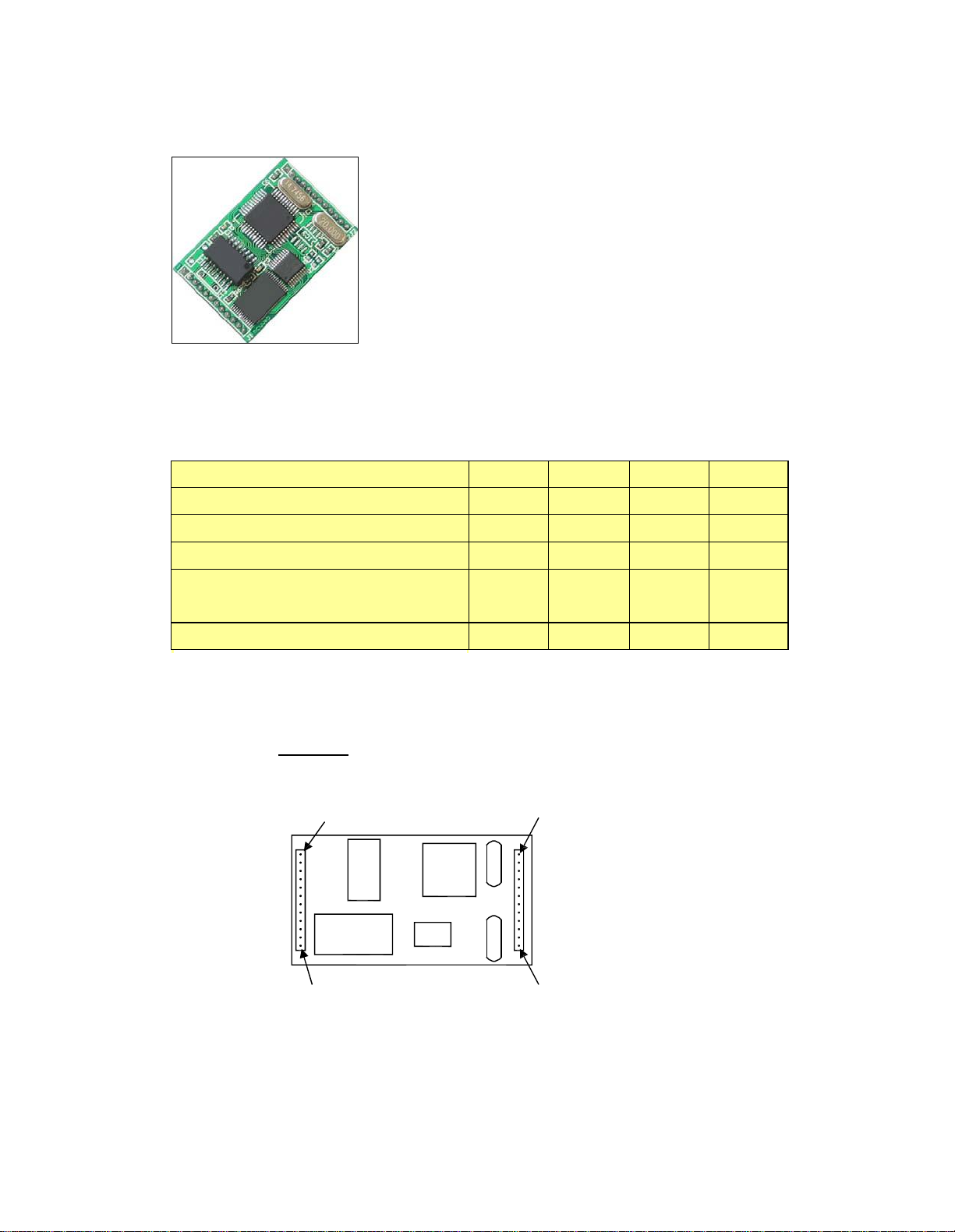
Pins Assignment
Top View
J1 Pin 1
J1 Pin 12
J2 Pin 1
J2 Pin 12
Page 2

J1 pins description
Pin 1
Gnd
Ground connection
Pin 2
Rx-
Ethernet Rx- connection
Pin 3
Rx+
Ethernet Rx- connection
Pin 4
Gnd
Ground Connection
Pin 5
Tx-
Ethernet Tx- connection
Pin 6
Tx+
Ethernet Tx+ connection
Pin 7
Gnd
Ground connection
Pin 8
Act
Activate indicator LED connection (see scheamtic)
Pin 9
Link
Link indicator LED Connection (see scheamtic)
Pin 10
NC
No connection
Pin 11
Status
Status indicator LED connection (see scheamti c)
Pin 12
Vcc
5V connection
J2 pins description
Pin 1
Vcc
5V connection
Pin 2
RST
SPI reset
Pin 3
SCK
SPI clock
Pin 4
MISO
SPI MISO (Master In Slave Out)
Pin 5
MOSI
SPI MOSI (Master Out Slave In)
Pin 6
Gnd
Ground connection
Pin 7
Rxd
TTL/CMOS compatible receive pin
Pin 8
Txd
TTL/CMOS compatible transmit pin
Pin 9
Gnd
Ground connection
Pin 10
CTS
TTL/CMOS compatible CTS pin
Pin 11
RTS
TTL/CMOS compatible RTS pin
Pin 12
Gnd
Ground connection
Page 3
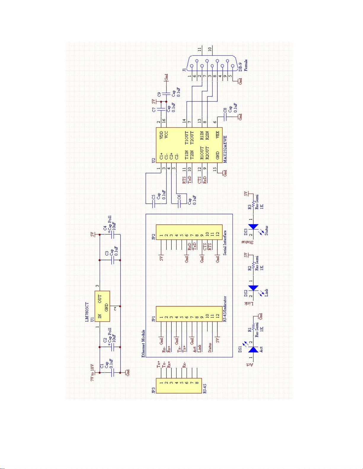
Figure 1 - Interfacing Ethernetto serial module with a PC serial por
t
Page 4

Figure 2 - Interfacing Ethernetto serial module with Microchip microprocessor
Page 5

One time configuration procedure for the Ethernet to serialmodule
10/100
Router
Ethernetmodule
Unknown IP
Figure 3 - Connection neededfor assigningtheIP addressfor
the Ethernetmodule
1) Connec
t t
he Etherne
t t
o serial moduleto a PC via a switch or router
PC
192.168.2.188
.
Page 6

Figure 4 - Configuration utility start-up screen
2) Download and open the configuration utility
3) Click SEARCH to findthe Ethernet to serial module.
.
Page 7

Figure 5 - Ethernet device found by the configuration utility
4) Highlightthe MAC addressfoundforthe Ethernetto serial module.
Page 8

Figure 6 - Store and Verify the settings with the configuration utility
5) Enter the Ethernetmodule IP address and setthe various parameters
required
6) Click WRITE to store the configurationtothe Ethernet module.
7) Click READ and verify the settings stored
.
.
Page 9

Verify the functionality of the Ethernet to serial module
(Refer to schematic on Figure 1)
Figure 7 - Setting up Hyper Terminal for testing the Ethernetto serial module
8) Open the Hyper Terminal program and enter a titleforthe Ethernetto
serial module terminal.
Page 10

Figure 8 - Choosing the TCP/IP Winsock in Hyper Terminal
9) Choose the TCP/IP Winsock so that the Hyper Terminal can send and
receive data to the Ethernetto serial module
.
Page 11

Figure 9 - Setting the correct IP address and portforthe TCP/IP Winsock
10) Enter theIP address of the Ethernetto serial module
.
Page 12

Figure 10 - Settingthe correctspeed for the serial port in a new Hyper
Terminal Window
11) Open a new Hyper Terminal and setthe correct serial port parameters.
Page 13

Figure 11 - Two Hyper Terminals showing successful connection
12) The Serial Port Terminal should display the character typed onthe
Ethernet moduletesting terminal, vice versa.
 Loading...