

Page 1

HXSP-1004
4 ports
RS-232 or RS-485/422
serial device server
user manual
Page 2

【Summary】
4 ports serial device servers which can contact with network fast. it
provides one line RS-232/485/422 (RS-232: DB9M: RS-484/422 / 4 bits terminal block) and
1line 10Base-T, it can manage the disperse serial device or host computer by network, easily and
convenience. Setting or software upgrade by serial program group in applying. Support TCP, UDP,
ARP, ICM and DHCP protocol, support Windows Native COM and auto-contact function once the
network intermit.
In addition, 4 ports serial device servers provide the managed collocate tools
that based Windows flat roof. it can lead the user manage and configure facility step by step, all of
the setting can be done by network or serial .Support pass gateway and router, easily for user to set IP
address, Server and Client mode , size of data and so on, Can realize the serial device contact with
network
by simply setting.
Model name: HXSP-1004A, HXSP-1004B
【Package checklist】
While using this converter for the first time, please check whether the packaging is
intact, the random attachment is complete at first.
Serial server
User manual
Power adapter 5VDC
Straight network cable
Software CD-ROM
The accurate device is put in the apparatus, please pay attention to handling with care, avoid
violent vibration, so as not to influence equipment performance. If you find the apparatus has been
damaged or lost any part in the course of transporting, please notify the distributor of our company
or our company, we will solve properly for you as soon as possible.
【Feature】
Support RS-232/RS-485/RS-422
Support Socket application.
Support Sever and Client mode.
Support Windows/Linux COM serial driver mode.
Support TCP,UDP,ARP, ICMP and DHCP protocol
Support all of Windows Native COM and auto-contact function once the network blackout.
Support passing gateway and router.
All of the setting can be done by network and serial
Proper Serial auto-connection (On-the-fly)
【Capability】
Ethernet port
Standard: 10Base-T, 100Base-TX
Protocol: support TCP, UDP,APR, ICMP and DHCP protocol
Signal: Rx+, Rx-, Tx+, TxSpeed: 10/100Mbps
Working format: full or half of duplex
Work mode: support Server and Client mode
Port memory: 512byte
Transmit distance: 100m
Page 3
Interface protection: 1.5KV ESD
Interface type: RJ-45
Serial interface
EIA RS-232, RS-485, RS-422 standard
RS-232 signal: TxD, RXD, RTS, CTS, DTR, DSR, DCD, GND
RS-422 signal: Tx+, Tx-, Rx+, Rx-, GND
RS-485 signal: Data+, Data-, GND
Parity: None, Even, Odd, Space, Mark
Data bit: 7bit, 8bit
Stop bit: 1, 1.5, 2
Baud rate 150bps~230400bps
Flow control: RTS/CTS or non-flow control
RS485 data direction: ADDC (Auto data direction Control)
Loading: RS-485/422 side support 32 nodes (optional 128 nodes)
Transfer distance: RS-485/422 side: 1200m, RS-232 side: less than 15m
Serial line protect: 1500W surge protect, 15KV magnetic isolation
Interface type: RJ-45
Power supply
Power supply input: 5VDC
Consumption:300mA
Environment
Operating temperature: -20℃~60℃, 5~95% RH
Storage temperature: -25℃~85℃, 5~95% RH
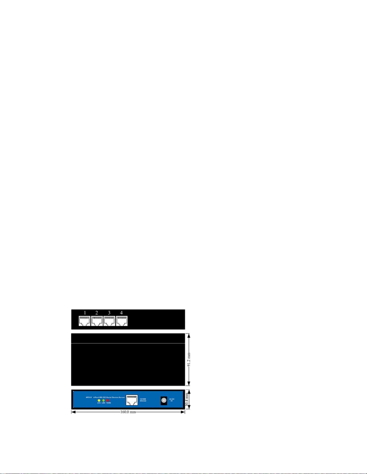
Appearance
Color: Black
L×W×H: 160mm×91.2mm×30.4mm
Material: Iron (shell)
Weight: 230g
【Panel】
1. HXSP-1004
HXSP-1004A is 1 port 10/100Base-T(X) to 4 ports
RS-232,
HXSP-1004B
is 1 port 10/100Base-
T(X)
to 4 ports RS-485/422, the appearance is the same.
Page 4

pin
MDI signal
MDI-X signal
1
TX+
RX+
2
TX-
RX3
RX+
TX+
6
RX-
TX4, 5, 7, 8
—
—
DC-IN: 5VDC power supply input
10/100M Ethernet: 10/100Base-T(X) Ethernet input and output
ACT LED indicator: Bright all along when connect power supply
LINK LED indicator: Bright all along when connected
RX/TX LED indicator: Bright all along when connect to the network, Flash
when data transfer
1, 2, 3, 4: RS-232 port (HXSP-1004A), RS-485/422 port (HXSP-1004B)
10/100Base-T Ethernet port
The 10/100BaseT(X) ports located on facility front panel. The PIN define of RJ45 port display as
follows, Connect by UTP or STP. The connect distance is no more than 100m. 100Mbps is used
100Ωof UTP 5, 10Mbps is used 100Ωof UTP 3, 4, 5.
RJ 45 port support automatic MDI/MDI-X operation. Can connect the PC, Server, Converter and
HUB by straight–though cable. Pin 1,2,3,6 Communication connect in MDI. 1→3, 2→6, 3→1,
6→2 are used as cross-over cable in the MDI-X port of
Converter and HUB.
10Base-T/100Base-TX are used in MDI/MDI-X, the PIN define in the table as below.
1 8
Note: “TX±” transmit data±, “RX±” receive data±, “—”not use.
MDI (straight-through cable):
RJ45
8
1
TX+
3
TX-
6
RX+
1
RX-
2
3 RX+
6 RX-
1 TX+
2 TX-
MDI-X (cross-over cable):
RJ45
8
1
(RX+)
TX+
3
(RX-) TX-
6
(TX+)
RX+
1
(TX-)
RX-
2
1 RX+(TX+)
2 RX-
(TX-)
3 TX+ (RX+)
6 TX- (RX-)
RS-232/485/422 interface
Page 5

PIN12345678
RS-232
TXD
RXD
RTS
CTS
DSR
SG
DTR
DCD
RS-485D+D-
GND
RS-422
RX+
TX+
RX-
TX-
FULL
GND
【Software installation and setting】
1 Set the IP address of the device
The IP address of the device and the PC must in the same subnet network
(the default IP address of the device is 192.168.1.233). First, must make the IP address of
the device in the same subnet network of PC.
If they are not in the same subnet network or the IP address have been used by another device,
Use Telnet change the IP address of the device
1 “Start”------“all programs”------“Running”
Input default IP address of the device “Telnet: 192.168.1.233”
2. Click “OK”, setting the IP of device by telnet. Choose the menu by
↑↓←→
of the
Page 6

keyboard and quit by “ESC” key.
3 Choose the “Server” menu and push “Enter” key, Change the IP of the device.
4 Change the IP (the changed IP must be in the same subnet of the PC). Push “Esc” key,
quit the network setting.
5 Push “Enter” key
Page 7

6 Push “Enter” Key, save the setting.
2. Create the Virtual COM port on the PC
Setup the “setup_nt_2K.exe” software, then you will find the “COM port over
tcp/ip.exe”
application in the control panel of windows OS.
Running the “COM port over tcp/ip.exe” application and create virtual COM port communicate
with the device on the PC.
Choose the name of the virtual COM port and click “Map” button, setting the parameter of the
virtual COM port as follows:
Page 8

1 Input the IP of the device
2 Input the NO. of the port of the device(Input 1~8)
3 Input 300
4 Default the parameter
Click the “OK”, Click “Save”. COM5 has been created.
Now, the COM5 can communicate with the terminal on the NO.1
port of the device.
Other Virtual COM port setting t he same as COM5
Note: Pay attention to the questions as below:
Page 9

(1) Please make sure that the power adapter is 5VDC
(2) When connect to PC, use cross-over cable.
(3) When connect to HUB or Switch, use straight-through cable
【Installation】
Note: Pay attention to the questions as below:
(1) Please make sure that the power adapter is 5VDC
(2) When connect to PC, use cross-over cable.
(3) When connect to HUB or Switch, use straight-through cable
【Application】
Application sketch map:
 Loading...