


Super Kit
User Guide
228-2500-750 V.20130930

2
Table of Contents
Kit Hardware Overview: ....................................................................................................3
Common part types and primary functions ................................................................................... 3
VEX IQ Kit Assembly Tips: ............................................................................................... 6
Removing Connector Pins ...................................................................................................................... 6
Fitting Small Gears, Pulleys, and Wheel Hubs onto Shaft .......................................................6
Keeping the Shaft Supported & Seated in Smart Motors & Assemblies ....................... 7
Using VEX IQ Hardware: ..................................................................................................8
VEX IQ Challenge ................................................................................................................. 9
Clawbot Instructions ...................................................................................................... 10
Part 1 Base ............................................................................................................................................... 10
Part 2 Claw ................................................................................................................................................ 28
Part 3 Tower ............................................................................................................................................. 42
Part 4 Ball Holder ................................................................................................................................... 58
Part 5 Sensors ......................................................................................................................................... 66
Autopilot Instructions .................................................................................................... 78
Control System Overview .............................................................................................85
Robot Brain Setup ........................................................................................................... 86
Robot Battery Charging and Usage ............................................................................................... 86
Radio Installation and Removal .........................................................................................................87
VEX Controller Setup ..................................................................................................... 89
Controller Battery Installation and Removal ..............................................................................89
Controller Battery Charging ............................................................................................................... 90
Radio Installation and Removal .........................................................................................................91
Initial Wireless Setup ..................................................................................................... 92
Power On and OFF .................................................................................................................................. 94
LED Indicators ................................................................................................................... 94
Robot Brain ................................................................................................................................................ 94
VEX Controller .......................................................................................................................................... 95
VEX Controller Buttons and Joysticks ........................................................................................... 95
Driver Control Program ................................................................................................ 96
Autopilot Program ...........................................................................................................97
LCD on the Robot Brain.................................................................................................99
Start Screen and List of Programs .............................................................................................100
Programs ................................................................................................................................................. 100
Run or Configure Driver Control ...................................................................................................100
Program Running Screen ...............................................................................................................101
VEX Controller Status ........................................................................................................................101
Smart Device Status...........................................................................................................................101
Configure Drive Control .....................................................................................................................102
Settings ..................................................................................................................................................... 103
Connector Ports and Buttons ........................................................................................................104
Charge Port (VEX Controller) .........................................................................................................104
Tether Port (VEX Controller and Robot Brain) .......................................................................105
Smart Device Ports .............................................................................................................................105
Connecting a Smart Motor .............................................................................................................106
Connecting a Bumper Switch .........................................................................................................107
Connecting a Touch LED ...................................................................................................................108
Connecting a Distance Sensor ......................................................................................................109
Connecting a Color Sensor ..............................................................................................................110
Connecting a Gyro Sensor ...............................................................................................................111
Appendix A
Battery Safety and Disposal ..................................................................................... 112
228-2779 VEX IQ Controller Battery Rules ...........................................................................112
228-2604 Robot Brain Battery Rules .......................................................................................112
228-2743 Robot Battery Charger .............................................................................................113
Software Update ..................................................................................................................................113
Getting Support .....................................................................................................................................113
Appendix B Compliance Statements ..................................................................... 114
FCC Compliance Statement (United States) ...........................................................................114
Industry Canada Compliance Statement .................................................................................115
Super Kit Inventory ...................................................................................................... 116
VEX IQ Super Kit ...................................................................................................................................116
3
Kit Hardware Overview:
If you can imagine it, you can build it with VEX IQ. Here’s an overview of common part types
and their primary functions to help you get started.
Common part types and primary functions
Beams
various sizes
Specialty Beams
angle, tee, right-angle beams
Plates
various sizes
Structural parts. Structural parts. Structural parts.
Connector Pins
various lengths
Standoffs
various lengths
Standoff Connectors
various types
Use with beams, plates, corner
connectors, and more.
Maintain desired spacing
between beams and plates.
Connect standoffs and connector
pins.
Corner Connectors
various types
Create corner connections
between beams, plates, or other
VEX IQ parts.
Mechanical Quick Start Guide
4
Shaft
various lengths
Shaft Bushing Shaft Lock Plates
various sizes
Transmit power to, or allow rotation
of, wheels, pulleys, gears, and
more.
Interfaces shafts with beams and
plates, allowing the shaft to spin
and be held in desired location.
Plates that lock onto shafts
allowing design components to spin
with the shaft.
Rubber Shaft Collars Twist Lock Shaft Collars Washers & Spacers
Holds objects on shafts and/or the
shaft itself in place.
Holds objects on shafts and/or the
shaft itself in place.
Use with shafts, reduces friction
and maintains desired spacing.
5
Pulleys
various sizes
Rubber Belts
various sizes
Rubber Band Anchor
Drive belts or make rollers and
small wheels.
Use with pulleys, as a form of
stored energy, and/or as a
fastener.
Use with rubber belts and bands.
Gears
various sizes
Wheel hubs and tires
various sizes
Smart Motor
Transmit power to another gear
and/or mechanism.
Rolling and powering movement. Creates rotary motion.
Mechanical Quick Start Guide
6
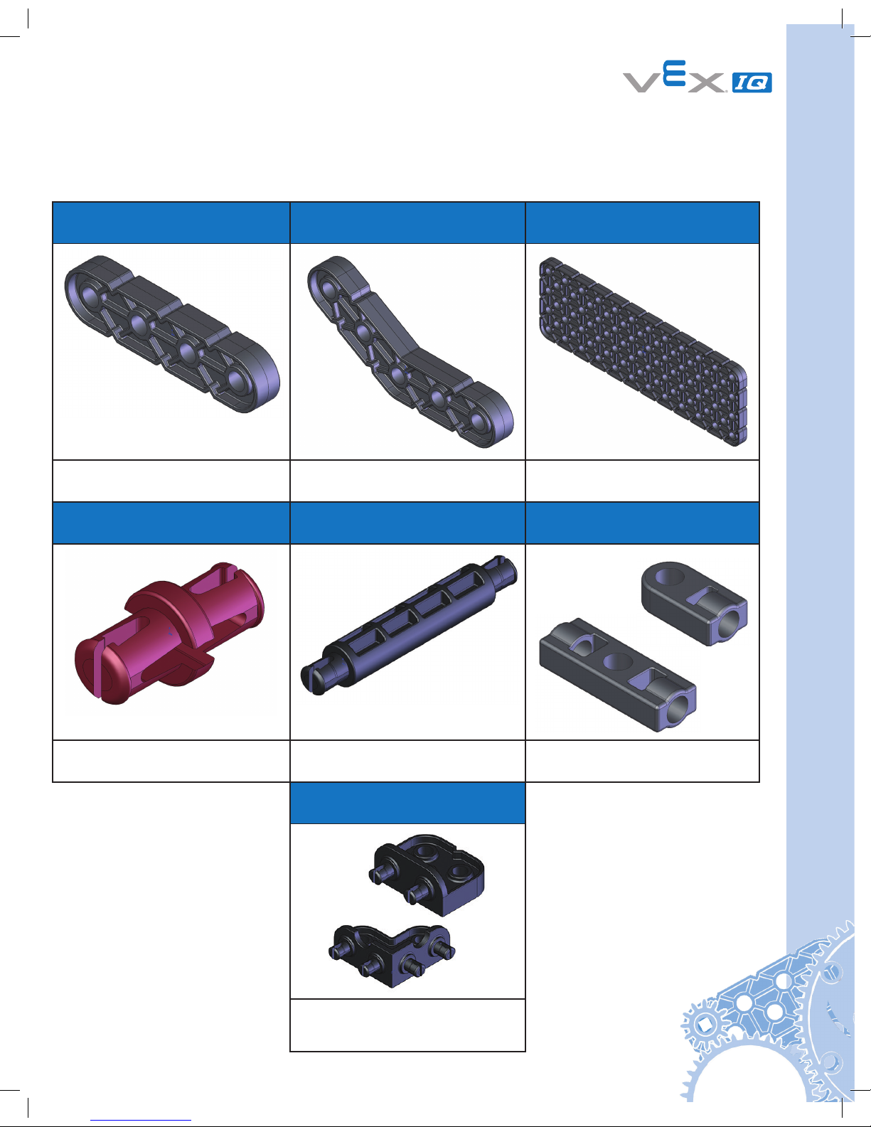
VEX IQ Kit Assembly Tips:
Removing Connector Pins
To remove connector pins from structural components, gently push the pin with your finger
from the back of the structural components to free it slightly, then it will be easier to pull it
out. Alternatively, a shaft can be used instead of a finger to push the pin from the back.
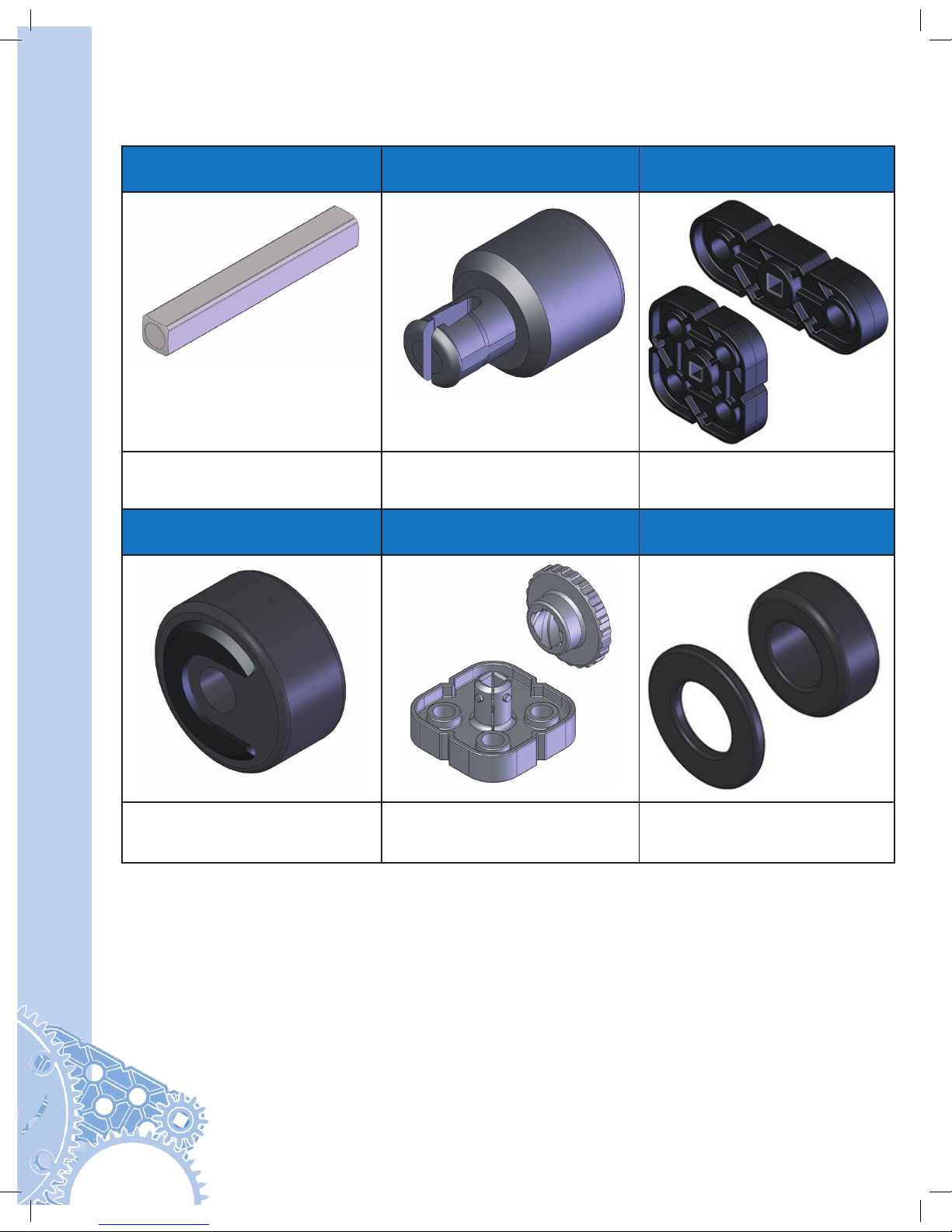
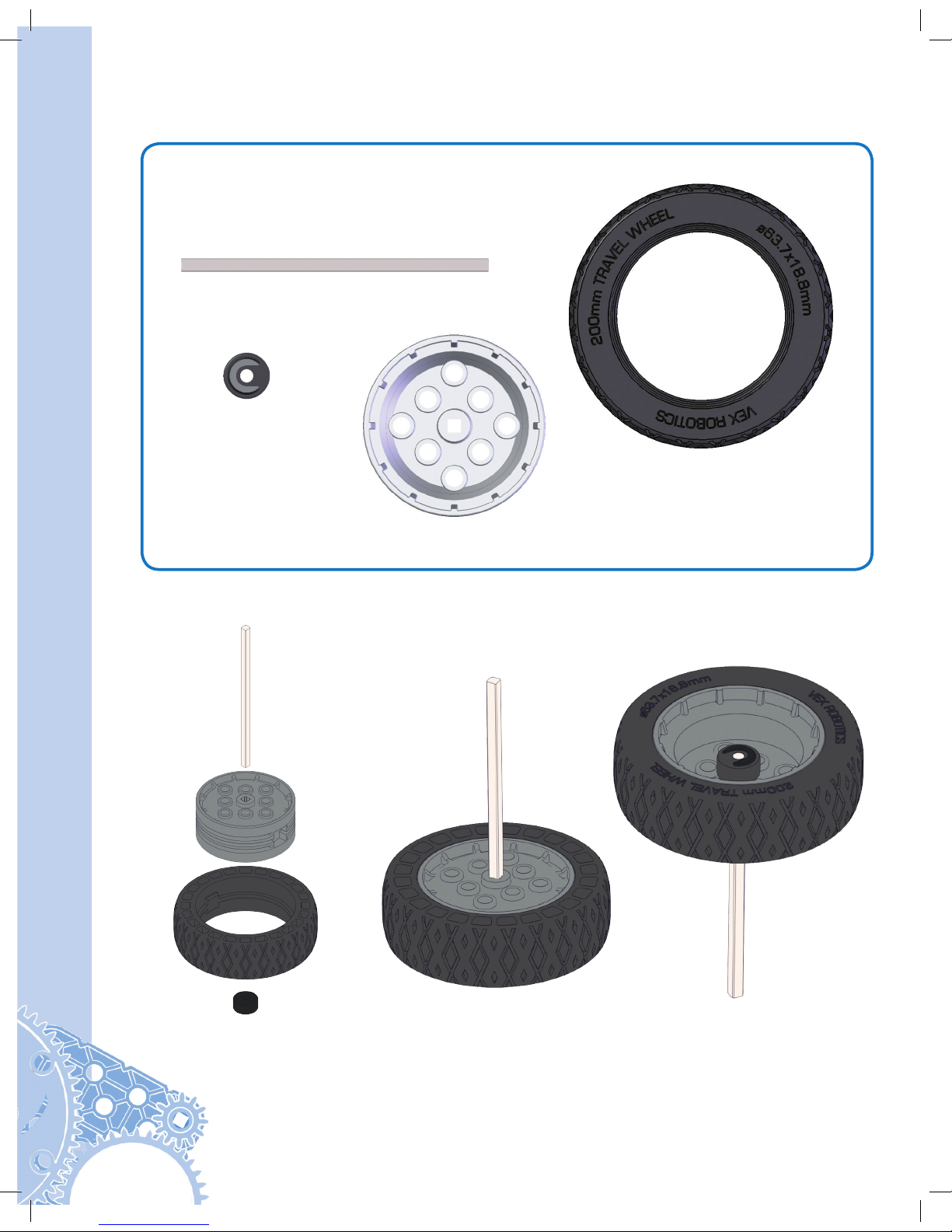
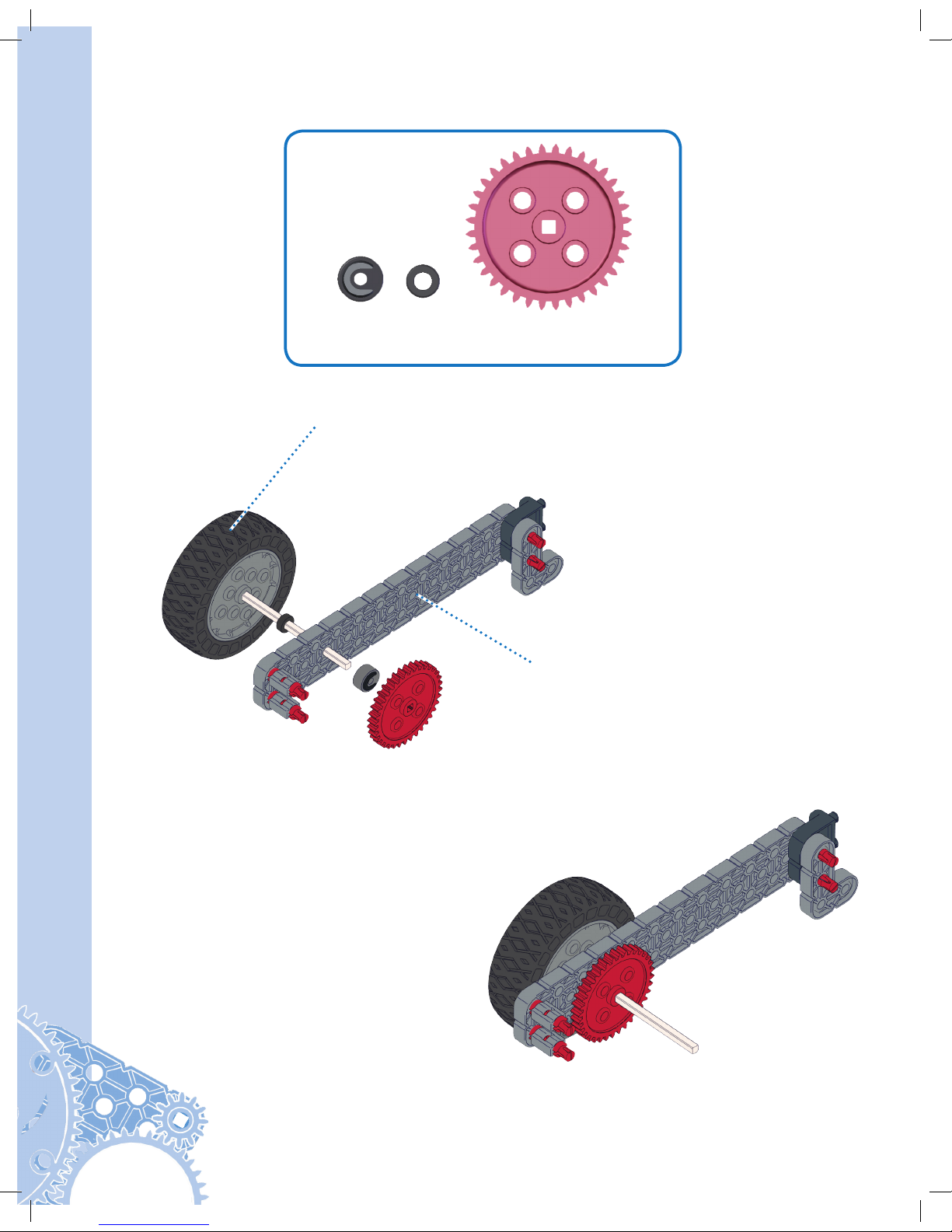
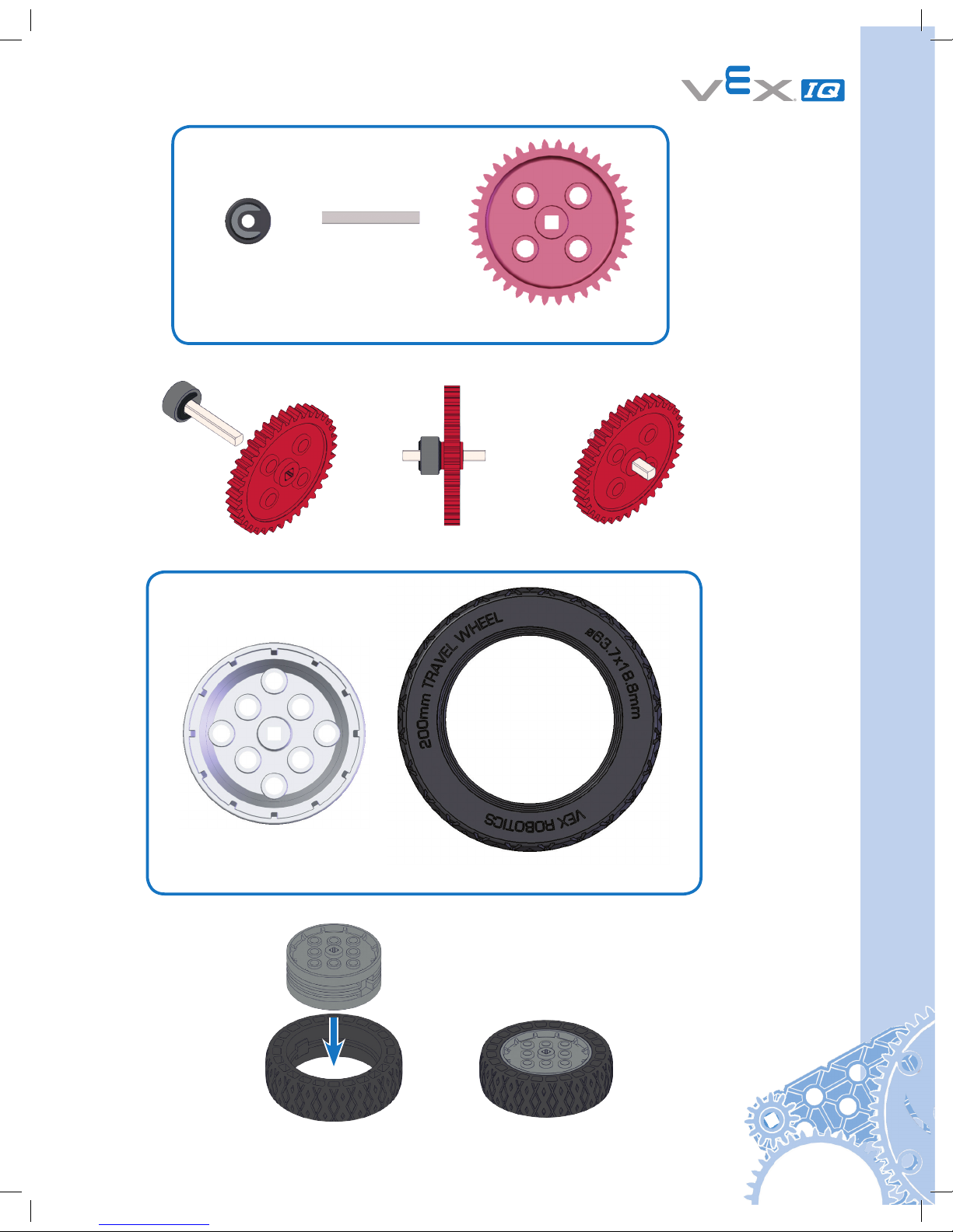
Fitting Small Gears, Pulleys, and Wheel Hubs onto Shaft
VEX IQ shafts are built to last and run flawlessly in powered applications. Gears, pulleys, and
wheel hubs fit very tightly on the VEX IQ shaft to ensure quality mechanisms with minimal
amounts of “wiggle”. Because of the intentionally tight fit, sliding smaller gears, pulleys, and
wheel hubs can be tough for some users. To help in this process, insert the shaft into a
large wheel hub (which acts as a temporary stand), then use the leverage from a beam or
plate to push the smaller gear, pulley, or wheel hub to the desired place. Then the temporary
stand can be removed and the shaft with small gears, pulleys, or wheel hubs can be
mounted on its mechanism.
Use Beam
To Help
Push Small
Gear
Temporary
Stand
7
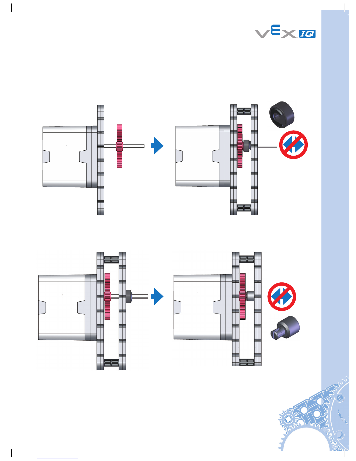
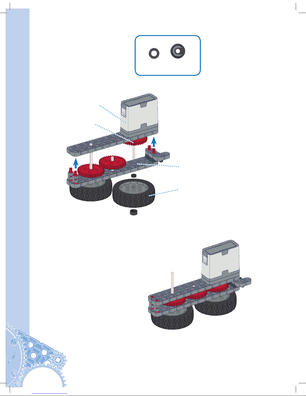
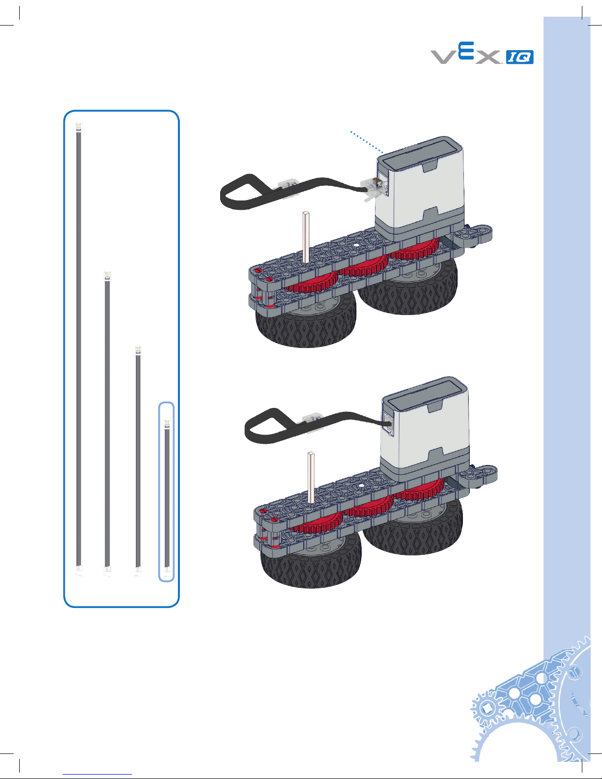
Keeping the Shaft Supported & Seated in Smart Motors & Assemblies
Having a motor turn a shaft in the VEX IQ system is accomplished easily with only a few
parts. However, without proper shaft support and either a rubber shaft collar and/or a shaft
bushing, the shaft will quickly shift or fall out of your mechanism or Smart Motor.
Improper Support
(Shaft can fall out)
Improper Support
(Shaft can fall out)
Proper Support
(Shaft can’t fall out)
Proper Support
(Shaft can’t fall out)
Mechanical Quick Start Guide
8
Using VEX IQ Hardware:
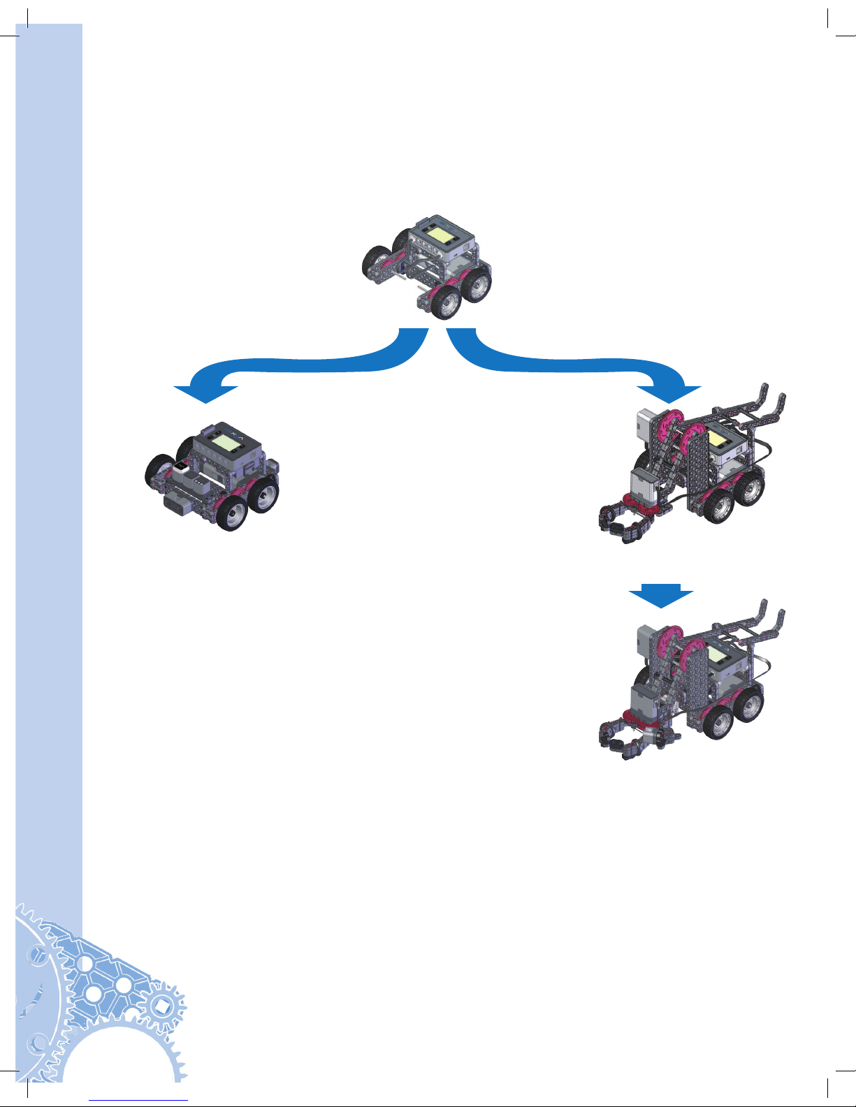
To get yourself acquainted with the VEX IQ system, build the Clawbot from the provided instructions
on the following pages. The VEX IQ Clawbot was designed to be quickly and easily assembled, and
then driven around using the included Driver Control program. The claw and storage “backpack” allow
you to drive around, pick up, and store a variety of small objects.
There are four options for assembling the Clawbot:
After you assemble your Clawbot, pages 85 through 111 contain important information
about how to setup and use the VEX IQ control system. Be sure to periodically visit
vexrobotics.com/vexiq/firmware to access the Software Update utility to ensure your
Robot Brain, Controller, Smart Motors, and Sensors all have the latest firmware.
Free curriculum, containing additional lessons and activities, including the use of the
Clawbot, is available at vexrobotics.com/vexiq/education. These lessons can help build
student confidence with the VEX IQ platform.
Make the Clawbot smarter with sensors.
Build instructions on:
• Gyro Sensor, pages 66-67
• Touch LED, pages 68-70
• Distance Sensor, pages 70-72
• Bumper Switch, pages 73-75
• Color Sensor, pages 76-77
Quick and versatile drive base. Build
instructions on pages 10-27.
Drive, pick up, and manipulate objects.
Build instructions on pages 10-65.
Turn your standard Drive Base into an
Autopilot explorer. Build instructions on
pages 10-27 and pages 78-84.
Clawbot with
Sensors
ClawbotAutopilot
Robot
Standard
Drive Base
9
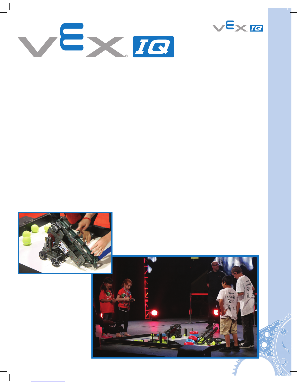
VEX IQ Challenge
Once you’ve mastered building the Clawbot, challenge yourself further with the VEX IQ
Challenge. Presented by the Robotics Education & Competition Foundation, the VEX IQ
Challenge is a STEM program for elementary and middle school students (ages 8-14).
The power of the VEX IQ system combined with the REC Foundation’s years of experience
inspiring students through robotics competitions is giving younger students more affordable
access to the inspiration, excitement and learning that comes from participating in a STEM
challenge.
In the VEX IQ Challenge, students, with guidance from their teachers and mentors, build a
robot using the VEX IQ robotics platform to solve an engineering challenge that is presented
in the form of a game. VEX IQ Challenge teams will work together to score points in
Teamwork Challenges. Teams then get to show off their robot’s skills individually in the robot
and autonomous Skills Challenges. Students will also use an Engineering Notebook to develop
an understanding of the design process. In addition to building robots, the STEM Challenge
component of the VEX IQ Challenge encourages students to actively learn about science,
technology, engineering and math.
Local VEX IQ Challenge events are held in many different cities, states, and countries. Top
teams from around the world will participate in local, regional and national VEX Robotics
Competitions. Teams will then qualify for VEX Robotics international competitions and the VEX
Robotics World Championship event held each Spring.
Visit RobotEvents.com to find the date and location of
a VEX competition near you. Teams can register online
to get an official team number and Welcome Kit and
to sign up for VEX IQ Challenge events.
CHALLENGE
10
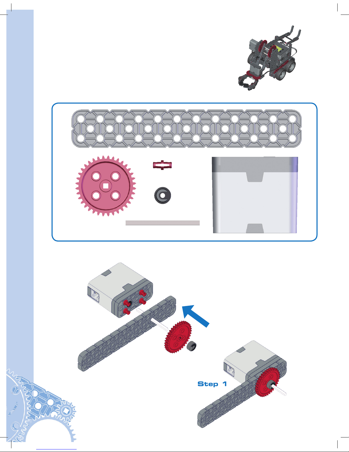
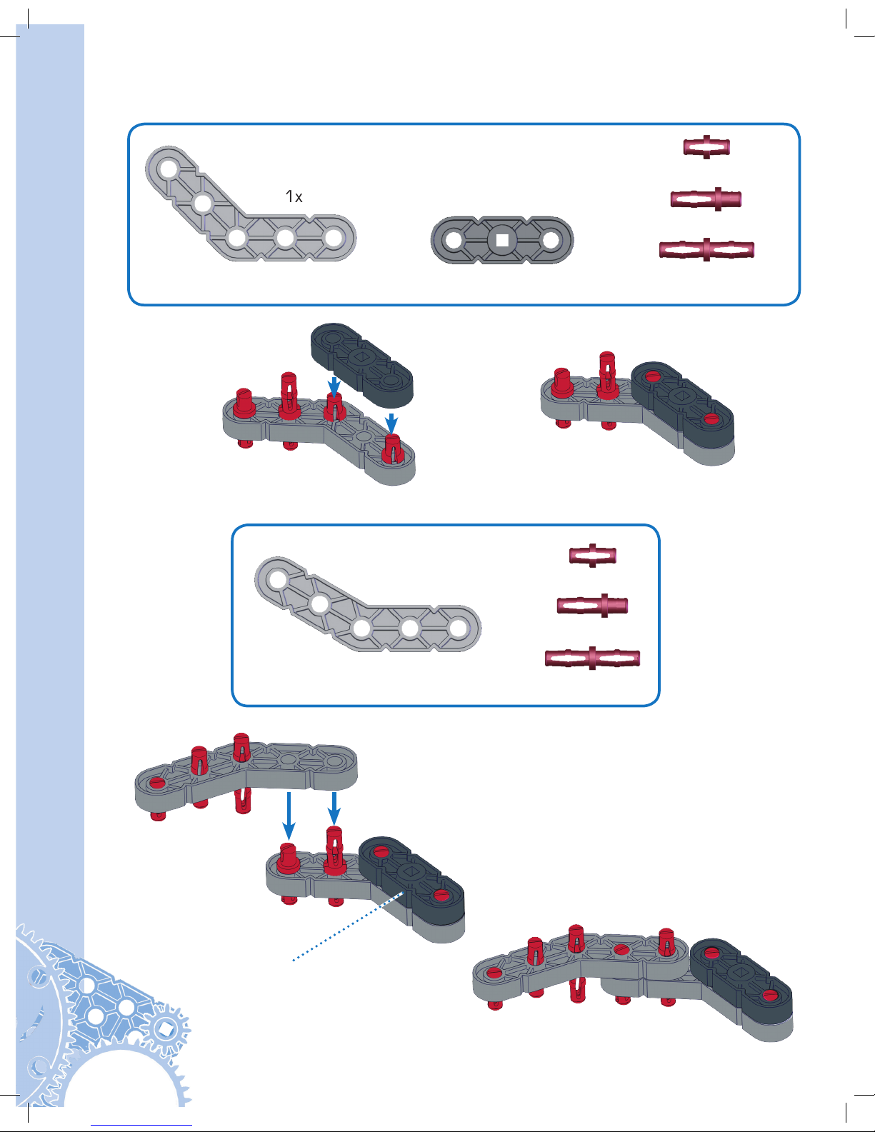
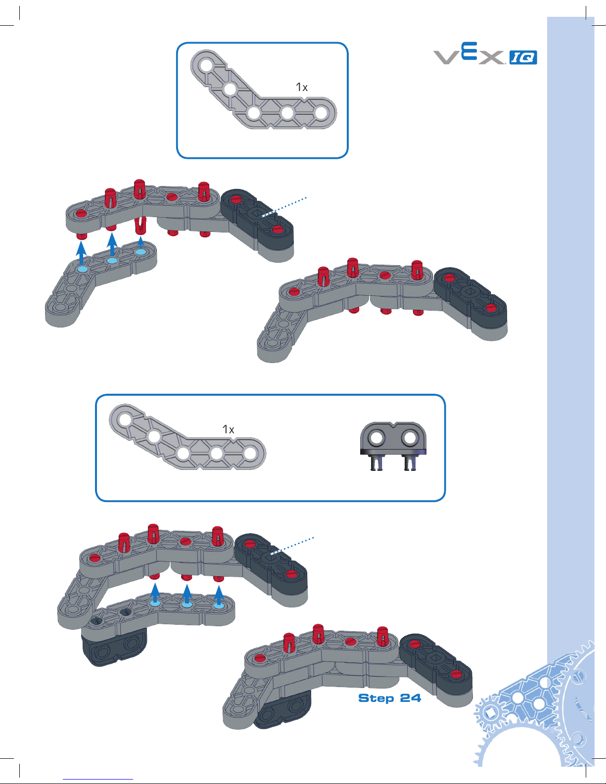
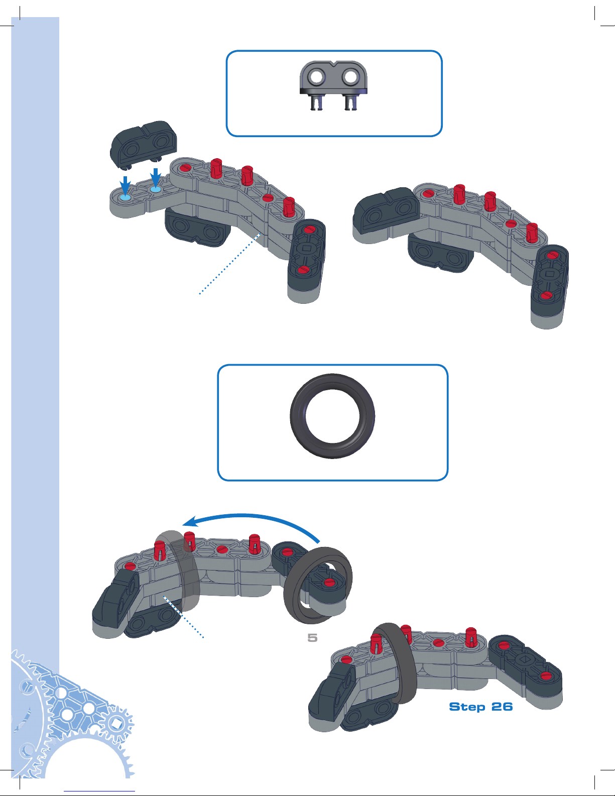
Clawbot Instructions
Clawbot Instructions
Part 1 Base
Step 1
Actual Size
1x
1x
4x
1x
1x
1x
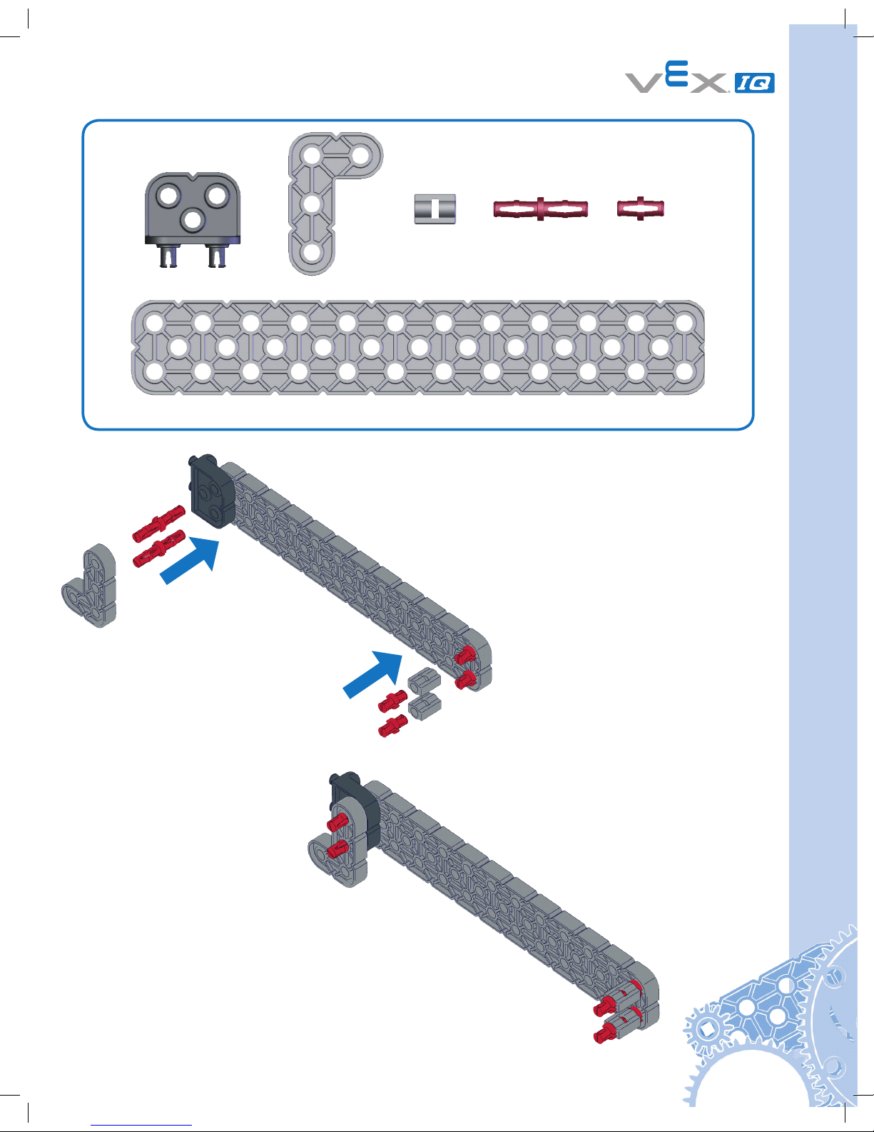
11
1x
2x
2x
4x
1x
1x
Step 2
Actual Size
12
Clawbot Instructions
1x
1x
1x
Step 3
1x
Actual Size
13
1x
1x
1x
Step 4
From Step 2
Actual Size
From Step 3
14
Clawbot Instructions
1x
1x
1x
Step 5
Step 6
1x
1x
Actual Size
Actual Size
From Step 4
15
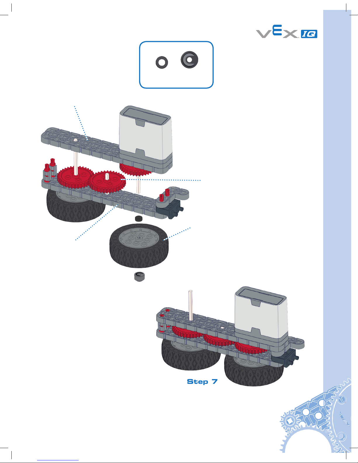
Step 7
1x1x
From Step 4
From Step 5
From Step 6
From Step 1
Actual Size
16
Clawbot Instructions
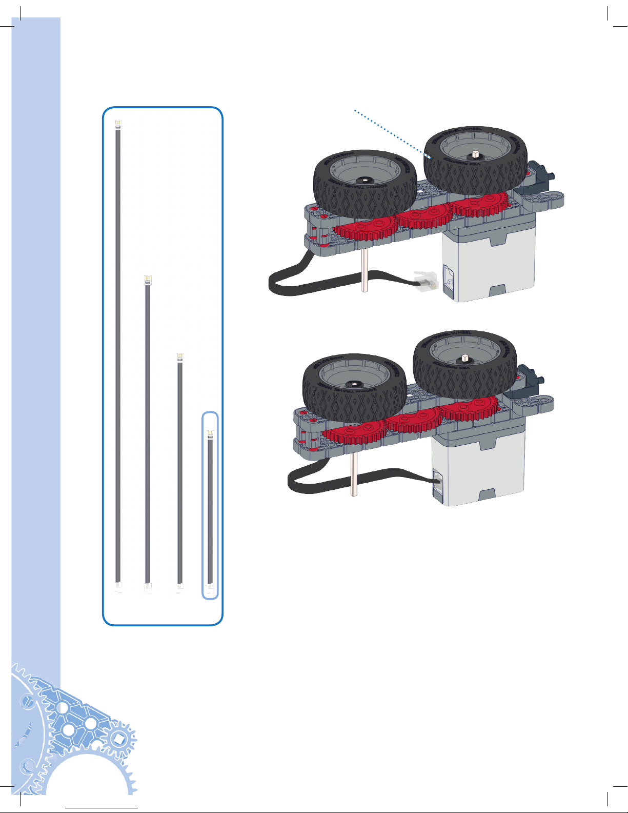
Step 8
From Step 7
1x
Not Actual Size
17
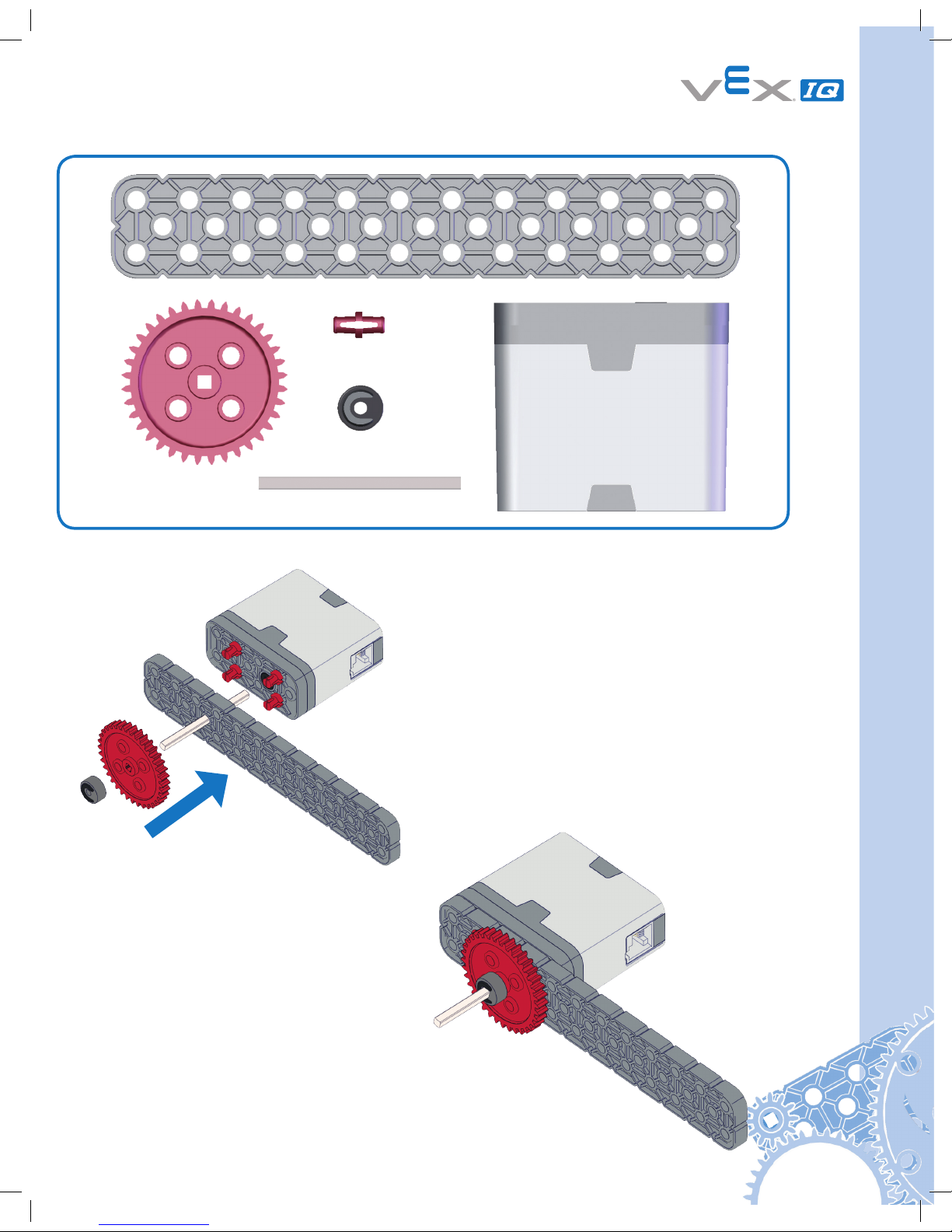
Step 9
Actual Size
1x
1x
4x
1x
1x
1x
18
Clawbot Instructions
Step 10
1x
2x
2x
4x
1x
1x
Actual Size

19
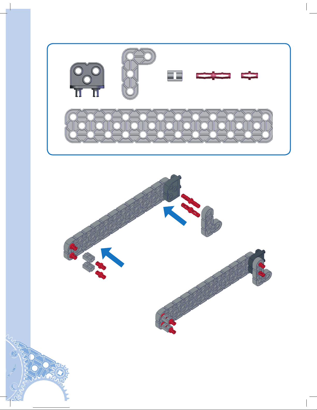
Step 11
1x
1x
1x
1x
Actual Size
20
Clawbot Instructions
Step 12
1x
1x
1x
From Step 11
From Step 10
Actual Size
21
Step 13
1x
1x
1x
1x
1x
Step 14
Actual Size
Actual Size
22
Clawbot Instructions
Step 15
1x1x
From Step 9
From Step 12
From Step 14
From Step 13
Actual Size
23
Step 16
From Step 15
1x
Not Actual Size
24
Clawbot Instructions
Step 17
1x
4x 4x
2x
2x
Actual Size
25
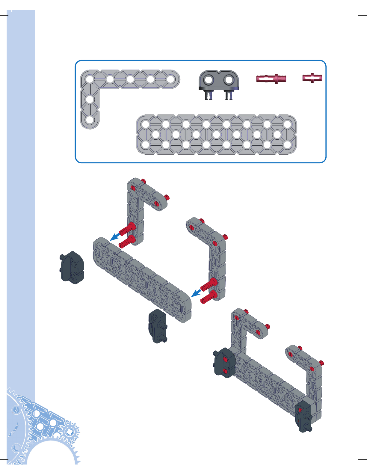
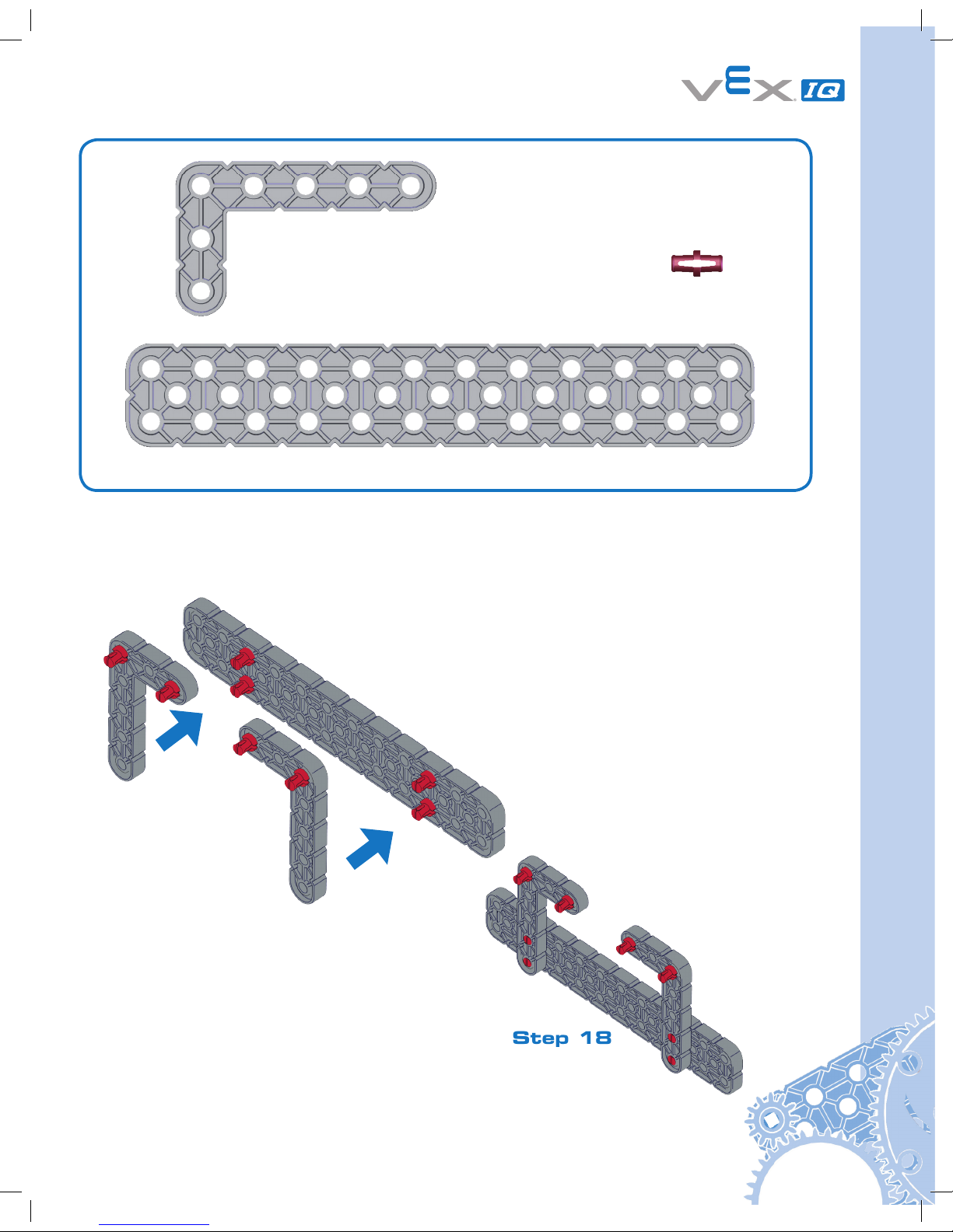
Step 18
1x
8x
2x
Actual Size
26
Clawbot Instructions
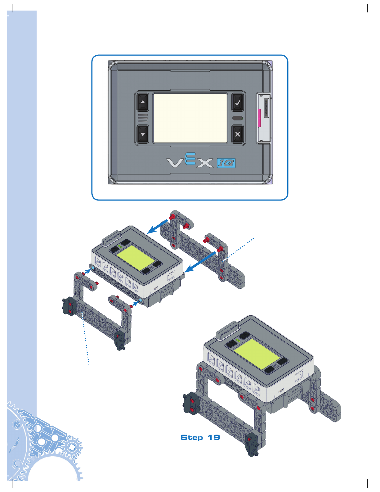
Step 19
1x
From Step 18
From Step 17
Actual Size
12
6
11
5
10
4
9
3
8
2
7
1
27
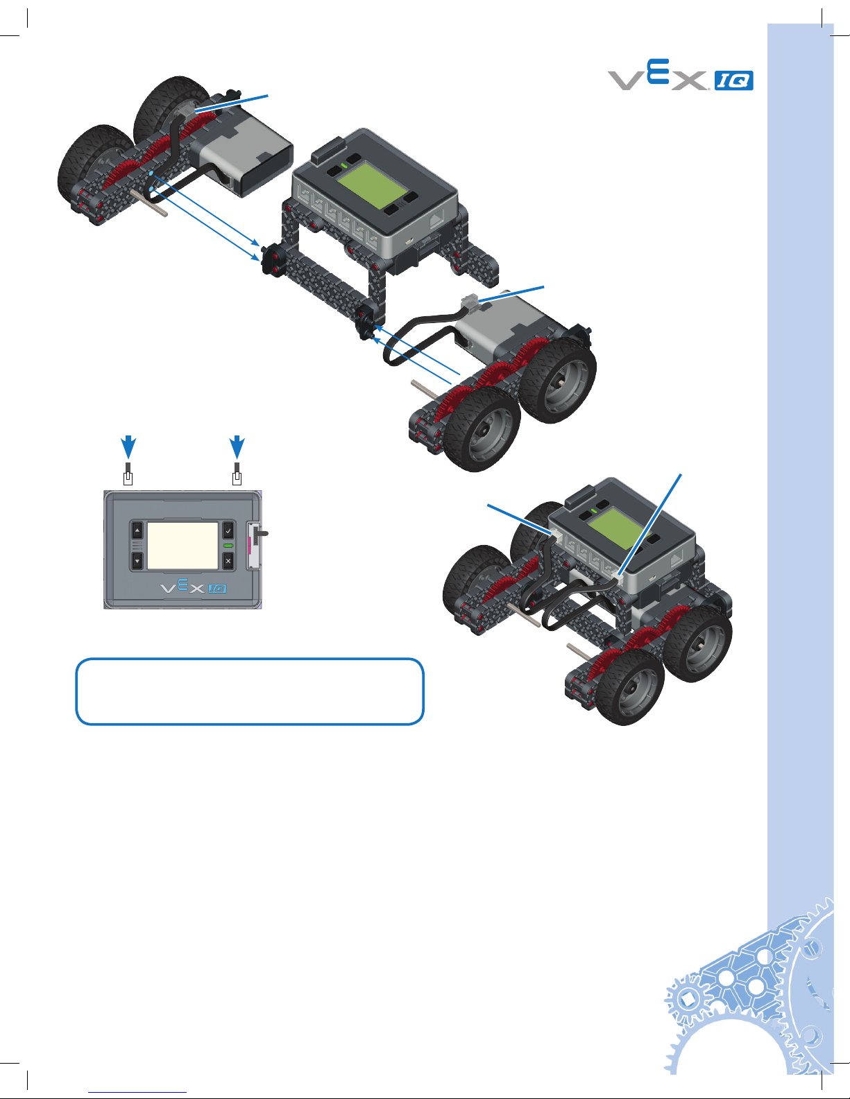
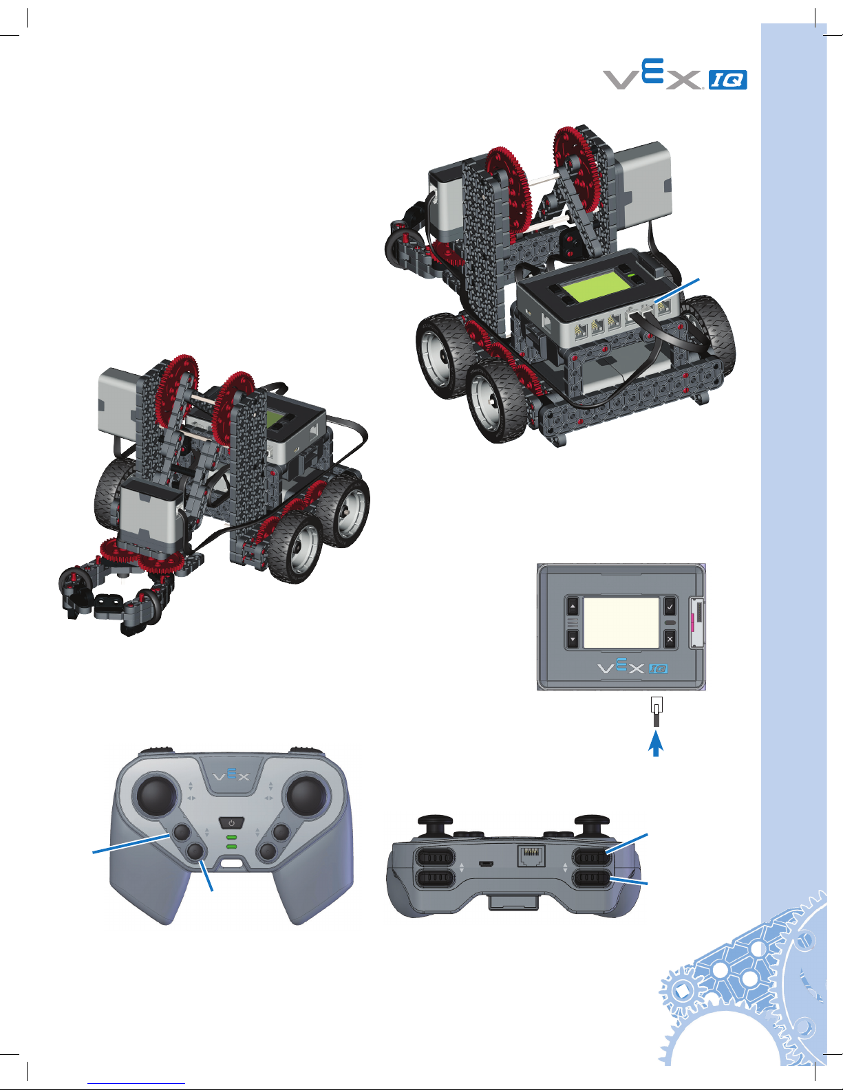
Step 20
Plug into Port 1
Port 6
Port 1
Plug into Port 6
Robot Base is now Ready to Run!
Test it before continuing the Build.
• Insert Robot Battery into Brain.
• Connect the Controller to the Robot Brain with the Tether Cable.
• Turn on the Robot Brain by pressing the check button.
• Run the Driver Control Program.
• Move the left joystick - does the left side move?
• Move the right joystick - does the right side move?
If the robot base does not perform as expected, refer to pages 85-111.
To continue building the Clawbot, follow the instructions on pages 28-65.
To build the Autopilot robot, follow the instructions on pages 78-84.
12
6115104938271
Refer to pages 85 through 111 for
information on the built in Driver
Control program in the Robot Brain.
28
Clawbot Instructions
Part 2 Claw
2x
1x
1x
1x
1x
1x
1x
1x
1x
Step 21
Step 22
From Step 21
Actual Size
Use the 45° Angle
Actual Size
Use the 30° Angle
29
1x
1x
1x
Step 23
Step 24
From Step 22
From Step 23
Actual Size
Actual Size
Use the 30° Angle
Use the 45° Angle
30
Clawbot Instructions
1x
1x
Step 25
Step 26
From Step 24
From Step 25
Actual Size
Actual Size

31
2x
1x
1x
1x
1x
1x
1x
1x
1x
Step 27
From Step 27
Step 28
Actual Size
Actual Size
Use the 45° Angle
Use the 30° Angle

32
Clawbot Instructions
1x
1x
1x
Step 29
Step 30
From Step 28
From Step 29
Actual Size
Actual Size
Use the 45° Angle
Use the 30° Angle

33
Step 31
From Step 31
Step 32
From Step 30
1x
1x
Actual Size
Actual Size

34
Clawbot Instructions
1x
2x
Step 33
Step 34
1x
1x
2x
Actual Size
Actual Size

35
Step 35
From Step 35
Step 36
From Step 34
From Step 33
1x
Actual Size

36
Clawbot Instructions
Step 37
Step 38
From Step 36
1x
2x
2x
Make
(2x)
Actual Size
Actual Size
From Step 37

37
Step 39
Step 40
From Step 39
From Step 38
From Step 26
From Step 37
1x
Actual Size

38
Clawbot Instructions
Step 41
From Step 32
From Step 41
Step 42
1x
Actual Size

39
2x
6x
Step 43
1x
Actual Size
Actual Size
Leave Shorter
for Motor
Clearance

40
Clawbot Instructions
4x
1x
Step 44
Actual Size
Actual Size
1x

41
From Step 43
From Step 44
Step 45

42
Clawbot Instructions
4x
Actual Size
1x
Actual Size
Part 3 Tower
1x
1x
2x
Step 46
From
Step 46
Step 47
Actual Size
From
Step 47
Step 48

43
Step 49
Step 50
Step 51
From
Step
49
From
Step 50
1x
1x
2x
Actual Size
4x
Actual Size
1x
Actual Size

44
Clawbot Instructions
1x
1x
2x
2x
1x
Step 52
From Step 52
Step 53
Actual Size
Actual Size

45
Step 54
From Step 53
Actual Size
2x
1x
1x
Use the 60° Angle

46
Clawbot Instructions
Step 55
From Step 55
Step 56
1x
Actual Size
1x
2x
2x
1x
Actual Size

47
1x
2x
Step 57
Step 58
From
Step 58
From
Step 48
Actual Size
2x

48
Clawbot Instructions
Step 59
From Step 58
From Step 20

49
Step 60
Step 61
From Step 59
From
Step 50
Rotate to Vertical
Attach to
Chassis
Slide onto Shaft

50
Clawbot Instructions
4x
1x
Step 62
Step 63
Actual Size
From Step 61
From Step 62
From Step 56

51
Step 64
From Step 56
1x
Actual Size
Step 65

52
Clawbot Instructions
Step 66
From Step 65
From Step 66
From Step 56
Step 67
1x
Actual Size

53
4x
1x
Actual Size
Step 68

54
Clawbot Instructions
From Step 68
Step 69

55
Actual Size
1x
Not Actual Size
Plug into Motor
Plug Into Port 10
1x
2x
12
6115104938271
From
Step
45
Use the 60° Angle
Step 71
Step 70

56
Clawbot Instructions
1x
Not Actual Size
Plug Into Motor
Step 72
57
LR
CHARGE TETHER
RADIO MODULE
POWER/LINK
A
E F
D
B C
CHARGE/GAME
Step 73
Plug
Into
Port
11
Raise
Arm
Lower
Arm
Robot Claw is now Ready to Run!
Close
Claw
Open
Claw
12
6115104938271

58
Clawbot Instructions
Part 4 Ball Holder
4x
Step 74
Actual Size

59
2x
Step 75
Actual Size

60
Clawbot Instructions
2x
2x
Step 76
Step 77
Actual Size
Actual Size

61
2x
2x
1x
1x
1x
Step 78
Step 79
Actual Size
Actual Size

62
Clawbot Instructions
1x
1x
1x 1x
2x
Step 80
Step 81
Actual Size
Actual Size

63
2x
1x
2x
1x
Step 82
Step 83
Actual Size
Actual Size

64
Clawbot Instructions
Step 85
Step 84
Step 86
From
Step
83

65

66
Clawbot Instructions
Part 5 Sensors
Gyro
Actual Size
4x
Step 1
1x
1x

67
Step 2
From
Step 1

68
Clawbot Instructions
Actual Size
3x
1x
Step 1
Touch LED

69
Actual Size
1x
From Step 1
Step 2

70
Clawbot Instructions
Step 3
From Step 2
Connect Touch LED
to any unused port on
Robot Brain using a
Smart Cable.
1x

71
Actual Size
4x
1x
Step 1
Distance Sensor

72
Clawbot Instructions
Step 2
Connect Distance
Sensor to any unused
port on Robot Brain
using a Smart Cable.
1x

73
Actual Size
1x
Step 2
Bumper Switch
Step 1
4x
1x
Actual Size
4x
From Step 1

74
Clawbot Instructions
1x
Actual Size
Step 3
Step 4
Actual Size
2x
From Step 2

75
Step 5
From Step 3
1x
Connect Bumper
Switch to Port 9 on
Robot Brain using a
Smart Cable.

76
Clawbot Instructions
Step 1
Color Sensor
Step 2
1x
2x
1x
1x
Actual Size
1x
Actual Size

77
Connect Color
Sensor to any
unused port on
Robot Brain using
a Smart Cable.
1x
Your Clawbot with Sensors
is now ready to Run!
Refer to pages 85-111 for important information about using your VEX IQ robot.

78
Autopilot Instructions
Autopilot Instructions
Step 1
Actual Size
6x
2x
From Step 20
on Page 27

79
2x
Step 2
Actual Size

80
Autopilot Instructions
Step 3
1x
Actual Size
4x
Connect Color Sensor to
any unused port on Robot
Brain with a Smart Cable

81
Step 4
1x
Actual Size
4x
Connect Gyro Sensor to
any unused port on Robot
Brain with a Smart Cable

82
Autopilot Instructions
Step 5
1x
Actual Size
4x
Connect Touch LED to
any unused port on Robot
Brain with a Smart Cable

83
Actual Size
4x
1x
Step 6
Connect Distance Sensor to
any unused port on Robot
Brain with a Smart Cable

84
Autopilot Instructions
1x
Actual Size
8x
Connect Bumper Switches to
any unused ports on Robot
Brain with a Smart Cable

85
Control System Overview
VEX Controller
Radio
Sensors
Robot Brain
Smart Motor
The VEX IQ Controller and Robot Brain
communicate with each other through either
wireless Radio Communication or Tether Cable.
The Sensors for VEX
IQ allow your robot
to collect information
and react to the
world around it.
The VEX IQ Controller is at the
center of what makes VEX IQ robots
fun to build and easy to use. The
controller allows you to drive your
robot immediately through the use
of two dual-axis analog joysticks and
eight buttons.
The VEX IQ Robot Brain is the
powerful command center of your
robot. With 12 identical Smart
Ports, a simple backlit LCD screen,
built in programs, and support for
custom programming from PC,
Mac and Linux computers, bringing
your robot to life has never been
easier.
The Smart Motor
converts electrical
energy from the
battery into rotational
energy. Motors are
an essential part of
the robot. They turn
wheels, move arms
and close claws.

86
Control System Guide
Robot Brain Setup
Robot Battery Charging and Usage
Items you need:
• Robot Battery Charger P/N: 228-2743
• Battery Charger Power Cord appropriate for your region
• Robot Battery P/N: 228-2604
See the Battery Safety information in the Appendices. Plug the Battery Charger Power Cord
into Robot Battery Charger. Plug the power cord into an AC outlet. Insert the Robot Battery
into the charger. The LED should turn red. The LED will turn green once the battery is
charged. The battery will continue to trickle (slowly) charge after the LED is green.
Robot Battery Charger LED
LED Color Status
Solid Green Battery is Fully Charged
Solid Red Battery Charge in Progress
Blinking Green Over Temperature Fault
Blinking Red Battery Fault
Turns red
or green.
LED

87
Slide the Robot Battery into the Robot Brain until the latch clicks. To remove the Robot
Battery, press the latch down and slide the battery out.
Radio Installation and Removal
Items you need:
• Robot Brain P/N: 228-2540
• 900 MHz Radio P/N: 228-2621
The Robot Brain is designed to use a variety of Radio types, including the 900 MHz Radio. Be
sure to use the same type of Radio in both the Robot Brain and the Controller.
Pull
Push
Down
on
Latch

88
Control System Guide
Ensure there is no battery plugged into the Robot Brain. Slide the Radio into the Radio
Socket. Orient the Radio so its VEX logo is away from the LCD screen. Press it in firmly.
In the event the radio needs to be removed, the Robot Battery must be removed. Press the
red button on the bottom of the Robot Brain while simultaneously pulling on the top of the
Radio.

89
Gently slide
Battery under
plastic tab.
Remove
Battery
Door.
Push Battery
flat.
Reinstall
Battery door.
Step 1
Step 2
Step 3
Step 4
VEX Controller Setup
Controller Battery Installation and Removal
Items you will need:
• Controller P/N: 228-2530
• Small Phillips head screwdriver
• Controller Battery P/N: 228-2779
Notice: See the Appendices for Battery Safety and Disposal information
Remove the battery door on the back of the Controller using a small Phillips head screwdriver.
Gently install the Controller Battery, ensuring that the “+” and “-” contacts align with the power
connector also marked “+” and “-”. Reinstall battery door.
90
Control System Guide
Controller Battery Charging
The VEX Controller Battery can only be charged while installed in the Controller. See the
Battery Safety information in the Appendices. There are two ways to charge the Controller
Battery:
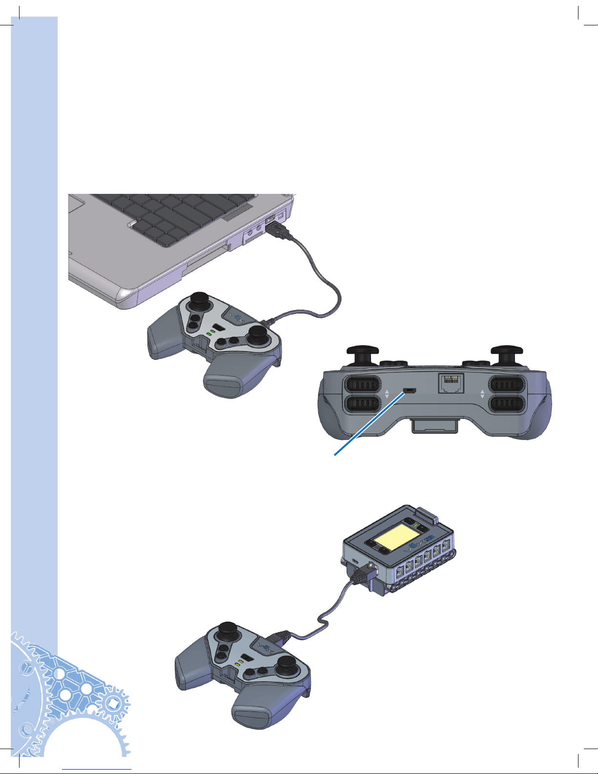
Option A: Turn off the Controller. Connect the Controller to a USB port on a PC or a USB Wall
Adaptor using the USB Cable P/N: 228-2785. Charging will start automatically. This is the
recommended charging method.
Option B: Turn off the Controller and Robot Brain. Connect the Controller to the Robot
Brain using a Tether Cable P/N: 228-2786. Turn the Robot Brain ON and charging will start
automatically.
LR
CHARGE TETHER
RADIO MODULE
Charge Port

91
Radio Installation and Removal
The Controller is designed to use a variety of Radio types, including the 900 MHz Radio
P/N: 228-2621. Be sure to use the same type of Radio in both the Robot Brain and the
Controller.
Slide the Radio into the Radio Socket. Orient the Radio so the VEX logo faces the top of the
Controller. Press it in firmly.
Controller Battery charging will take about 4 hours. While the Controller Battery is charging,
the Charge/Game LED on the Controller will be solid red. When the Controller Battery is fully
charged, the LED will change to solid green. See page 95 for detailed LED color diagram.
POWER/LINK
A
E F
D
B C
CHARGE/GAME
Charge / Game LED
Charge LED Color Status
Solid Green Battery is completely charged
Solid Red Battery charge in progress
Blinking Red Battery fault
Off Not charging
Charge
LED

92
Control System Guide
Removing the Radio should rarely, if ever, be done. To remove the Radio, first remove the
battery door using a Phillips head screwdriver. Pull firmly on the Radio to remove it.
Initial Wireless Setup
Items you will need:
• Robot Brain with Radio and Robot Battery installed
• VEX Controller with Radio and Controller Battery installed
• Tether Cable P/N: 228-2786
In order for the Robot Brain and Controller to communicate wirelessly, they must be paired
together. Before pairing these devices together, a radio and battery must be installed into
each of them. With both devices OFF, connect the Robot Brain to the Controller using the
Tether Cable.

93
Driver Control
Select Settings
Programs
Autopilot
Animated icon
Searching Icon - Searching for Controller
(not connected).
Tether Icon - Connected by Tether Cable.
Radio Link Icon - Connected by Radio
(number of bars indicates signal strength).
No Radio installed, no Tether connected.
Remove the Tether cable from Robot Brain and Controller. They are now communicating
wirelessly as indicated by the Radio Bar icon on the LCD screen. The Robot Brain’s LED and
the Controller’s Power/Link LED should be blinking green. Congratulations, your Robot Brain
and Controller are now paired!
If the Robot Brain and Controller are not linked (indicated by animated “Searching” icon), turn
them both OFF and repeat the process.
1 2 3 4
Turn the Robot Brain ON by pressing the Check button. The Controller will automatically link
and pair to the Robot Brain. The Tether Icon will appear on the Robot Brain LCD screen.
Tether Icon. See
table below for
explanation.
Icon Table

94
Control System Guide
LED Color Status
Solid Green Robot Brain ON - with NO Radio
Link (searching)
Blinking Green Robot Brain ON - with good Radio
Link
Solid Red Battery level low - with NO Radio
Link
Blinking Red Battery level low - with good
Radio Link
Power On and OFF
Robot Brain ON: Press the Check button.
VEX Controller ON: Press the Power button.
Power OFF
Turning off the VEX Controller or Robot Brain will automatically turn OFF the other unit, if the
units are connected wirelessly.
VEX Controller OFF: press and hold the Power Button for 2 seconds.
Robot Brain OFF: press and hold the “X” Button for 2 seconds.
LED Indicators
Robot Brain
The color of the LED indicates the status of the Robot Brain. Review table below. This
information is very helpful when working with the Robot Brain.
POWER/LINK
A
E F
D
B C
CHARGE/GAME
12
6
11
5
10
4
9
3
8
2
7
1
Check
Button
Power Button
“X” Button

95
VEX Controller
The color of the LEDs indicates the status of the Controller. Review table below. This
information is very helpful when working with the Controller.
Power / Link LED
Charge / Game LED
Power / Link LED Color Status
Solid Green VEX Controller ON - with NO
Radio Link (searching)
Blinking Green VEX Controller ON - with good
Radio Link
Solid Red Battery level low - with NO Radio
Link
Blinking Red Battery level low - with good
Radio Link
Charge / Game LED Color Status
Solid Green Battery is completely charged
Solid Red Battery charge in progress
Blinking Red Battery fault
Off Not charging
VEX Controller Buttons and Joysticks
The Controller has (4) joystick axes labeled A, B, C and D that are used to control the robot.
The further the joystick is moved in one direction, the faster the motor will spin. When the
joystick is at rest, the motors do not receive any signal to move.
POWER/LINK
A
E F
D
B C
CHARGE/GAME
LR
CHARGE TETHER
RADIO MODULE
The Controller also has 4 pairs of buttons labeled E, F, R and L. These buttons
turn the motors on at full speed in one direction. Each button pair controls the
clockwise and counterclockwise direction of the motor.
See the Driver Control Program for a mapping of the joysticks and buttons to the
ports on the Robot Brain, when using the built-in Drive Control program.

96
Control System Guide
POWER/LINK
A
E F
D
B C
CHARGE/GAME
Driver Control Program
The Driver Control Program is a default program built into the Robot Brain so it can be
used with the Controller without programming. It maps the Controller joysticks and buttons
to control specific ports on the Robot Brain. There are three modes in the Driver Control
Program: Left Stick, Right Stick, and 2 Joystick.
2 Joystick Drive
Left Drive Motor Right Drive Motor
Bumper Stops M10 in Rev Motor (M10)
Bumper Stops M4 in Fwd Motor (M5)
Bumper Stops M10 in Fwd Motor (M11)
Bumper Stops M4 in Rev Motor (M4)
M10 M4
Left Drive Motor Right Drive Motor
12
6115104938271
Drive RightDrive Left
M11 M5
Forward Spin Right Reverse Spin Left
In 2 Joystick mode, two joysticks will be used to drive the robot. The A axis on the left joystick
controls the left drive motor and the D axis on the right joystick controls the right drive motor.

97
POWER/LINK
A
E F
D
B C
CHARGE/GAME
Left Stick Drive Right Stick Drive
M10
M11 M5
M4
POWER/LINK
A
E F
D
B C
CHARGE/GAME
In both Left Stick and Right Stick mode, one joystick will be used to drive the robot. In Right
Stick the D axis on the right joystick will be used to drive the robot forward and backward. The
C axis will be used to turn the robot left and right. In Left Stick, the A axis on the left joystick
will be used to drive the robot forward and backward. The B axis will be used to turn the robot
left and right.
M10
M11 M5
M4
Joystick Up Right Down Left
Forward Spin Right Reverse Spin Left
Autopilot Program
The Autopilot program is a default program built into the Robot Brain so that your Autopilot
Robot (see pages 10 through 27 and continued on 78 through 84 for build instructions) can
explore a room by itself - no Controller needed. It contains three built-in in modes for exploring:
random, spiral, and lawnmower mode. The three diagrams on the next page show these
behaviors:

98
Control System Guide
Random Mode Spiral Mode Lawnmower Mode
The robot will randomly
explore your room by driving
in a straight line. When it
encounters obstacles, it
will backup, spin a random
amount, and depart in a new
direction.
This is the default Autopilot
explore mode; tapping the
Touch LED during this mode
will change to Spiral Mode.
The Touch LED will illuminate
red when in this mode; when
the Color Sensor sees a red
object, the robot will change
to this mode.
The robot will begin to explore
by driving in a spiral with an
ever increasing radius. When
it encounters an obstacle, the
robot will drive to a new location
and begin to spiral again.
Tapping the Touch LED during
this mode will change to either
Lawnmower Mode if a Gyro
Sensor is attached, or Random
Mode if the Gyro Sensor is not
attached.
The Touch LED will illuminate
blue in this mode; when the
Color Sensor sees a blue object,
the robot will change to this
mode.
The robot will begin to
explore your room by driving
back and forth, as if it were
mowing a lawn. When it
encounters an obstacle, it
will turn away and continue
in the opposite direction.
Tapping the Touch LED
during this mode will change
to Random Mode.
The Touch LED will illuminate
green in this mode; when
the Color Sensor sees a
green object, the robot will
change to this mode.
The Autopilot program requires at least two Smart Motors and either one Distance Sensor
or up to two Bumper Switches to operate. Having both a Distance Sensor and two Bumper
Switches connected will enhance the ability of the Autopilot Robot to explore its environment.
The maximum number of sensors that the Autopilot program will utilize are:
• (2x) Bumper Switch, mounted on the back side of the robot.
• (1x) Distance Sensor, mounted on the front side of the robot
• (1x) Touch LED
• (1x) Color Sensor
• (1x) Gyro Sensor

99
Driver Control
Select Settings
Programs
Autopilot
LCD on the Robot Brain
The LCD is a very powerful tool to help configure and operate the Robot Brain.
Up
Button
Radio SignalMenu Title
Menu
Option
Battery Voltage
Check
Button
“X” Button
Down Button
Check Button Functions “X” Button Functions
The default explore mode is Random Mode. To change between the three different modes, a
Touch LED and or Color Sensor must also be connected to the Robot Brain. Tapping the Touch
LED will cycle through the available explore modes. The current explore mode will be shown
by illuminating the Touch LED in red for Random Mode, blue for Spiral Mode, and green for
Lawnmower Mode. When the Color Sensor sees a red, blue or green object, it will cause the
robot to enter into the explore mode associated with that color.
Sometimes, the Autopilot Robot may get stuck, such as between the legs of a chair or stool. If
this occurs, the robot will stop moving and the Touch LED will blink on and off. Picking up the
robot and moving it to a new location will allow the robot to continue exploring.

100
Control System Guide
Start Screen and List of Programs
Programs
The Programs Screen of the Robot Brain is the first screen displayed after turning on the
Robot Brain, and will contain a list of all programs that have been downloaded to it. The
default program is Driver Control, which allows you to use and control up to eight Smart
Motors and four Sensors.
If additional programs have been downloaded to the Robot Brain, use the Up/Down arrows
to navigate between programs. The currently selected program will be highlighted; to run the
selected program, press the Check button.
Run or Configure Driver Control
Programs › Driver Control
The Driver Control program is unique in that it contains the ability to customize the way it
runs. This program is the default program loaded onto the Robot Brain.
When selecting the Driver Control program from the Programs Screen, two additional
options are presented: Run or Configure. Use the Up/Down buttons to select the Run option,
and press the Check button to begin running this program with the default settings.
Use Up/Down arrows to highlight Driver Control, then press the Check button.
Use Up/Down arrows to highlight Run, then press the Check button.
Run
Configure
Select Exit
Driver Control
Driver Control
Select Settings
Programs
Autopilot
 Loading...