

Page 1
Page 2

Description
HP-L-8.9 T2 Scanner user manual V1.1.0 (08/06/2016) 2
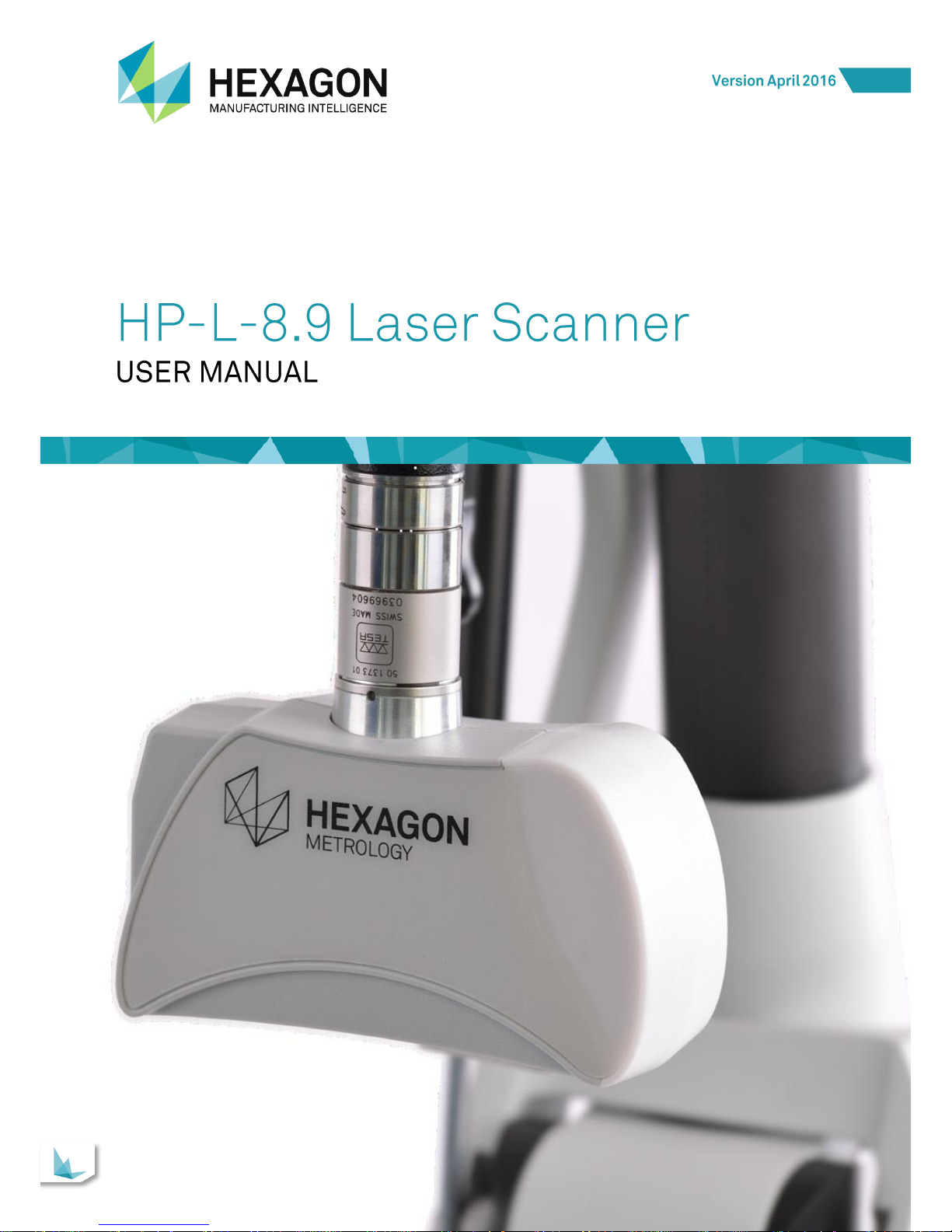
HP-L-8.9 Scanner
User Manual
www.HexagonMI.com
Hexagon Metrology Division ROMER
Z.A. des Bois Blanche.
F- 41800 MONTOIRE-sur-le Loir France.
Tel: +33.2.54.86.40.40
Hexagon Metrology Inc.
3536 Seagate Way, Suite 100
OCEANSIDE, California 92056 U.S.A.
Tel: +1 760-994-1401
Page 3

Description
HP-L-8.9 T2 Scanner user manual V1.1.0 (08/06/2016) 3
INTRODUCTION
Dear customer, thank you for purchasing a HEXAGON® product. Before starting any operation with
your 3D Scanner, please read these instructions.
This guide describes how to install the HP-L-8.9 on your ROMER Absolute Arm.
For further information, please contact your local Hexagon Manufacturing Intelligence agent.
IMPORTANT NOTE
All information contained in this document is subject to be modified without any notification and
does not represent any engagement from HEXAGON AB. The hardware described in this manual
is furnished under licence agreement and must be used only in conformity with the terms of this
licence. No part of this manual may be reproduced or transmitted under any form or by any way,
electronic or mechanical, including photocopy or recording, for any purpose without Hexagon AB
formal authorisation.
DISCLAIMER NOTE
All non-authorised modification, repair or bad use of the Hexagon system will automatically void the
original manufacturer’s guaranty. The manufacturer is not responsible for caused by unauthorised
handling, or use, of this material. For information regarding the warranty, repair, technical
assistance, latest updates and current information prices, please contact your local Hexagon
Manufacturing Intelligence agent.
PICTURES
The pictures in this manual are not contractual.
Page 4
Description
HP-L-8.9 T2 Scanner user manual V1.1.0 (08/06/2016) 4
IMPORTANT SAFETY NOTE
The following directions should enable the person responsible for the product and the person using
the product to anticipate and avoid operational hazards.
The person responsible for the product must ensure that all users understand these directions and
adhere to them.
The user of the product must read carefully all notes in the Appendix regarding mechanical and
electrical safety, battery operation, correct use of the product and all other safety information before
unpacking the system.
WARNING
Incorrect use can lead to personal injury, equipment malfunction and/or damage. The person
responsible for the product should inform the user about hazards and how to counteract them. The
product should not to be operated until the user has been instructed on correct use.
Responsibilities
Manufacturer of the product
Hexagon Metrology Division ROMER, is responsible for supplying he product, including the user
manual and original accessories, in a complete and safe condition.
Manufacturer of non- HEXAGON® accessories
The manufacturer of non-Hexagon accessories for the product is responsible for developing,
implementing and communicating safety concepts for their products, and is also responsible for the
effectiveness of those safety concepts in combination with the Hexagon product.
Person in charge of the product
The person in charge of the product has the following responsibilities:
To understand the product's safety instructions and user manual instructions.
To be familiar with local regulations relating to safety and accident prevention.
To inform Hexagon Manufacturing Intelligence immediately if the product and the application
becomes unsafe.
To ensure that the national laws, regulations and conditions for the operation of radio
transmitters are respected.
Environment & safety
The product is suitable for use in an atmosphere appropriate for permanent human habitation. The
product is not suitable for use in harsh or explosive environments.
NOTICE
Accuracy deterioration
Before any use, always ensure nothing adverse happened on the probe (accuracy verification)
NOTICE
The Feature Pack FP4 (HP-LC-200, dedicated to the HP-L-20.8) is not compatible with the use of
the HP-L-8.9.
Any deterioration due to the use of the HP-L-8.9 with a FP4 Feature Pack will avoid the guaranty.
Page 5
Description
HP-L-8.9 T2 Scanner user manual V1.1.0 (08/06/2016) 5
Safety Information
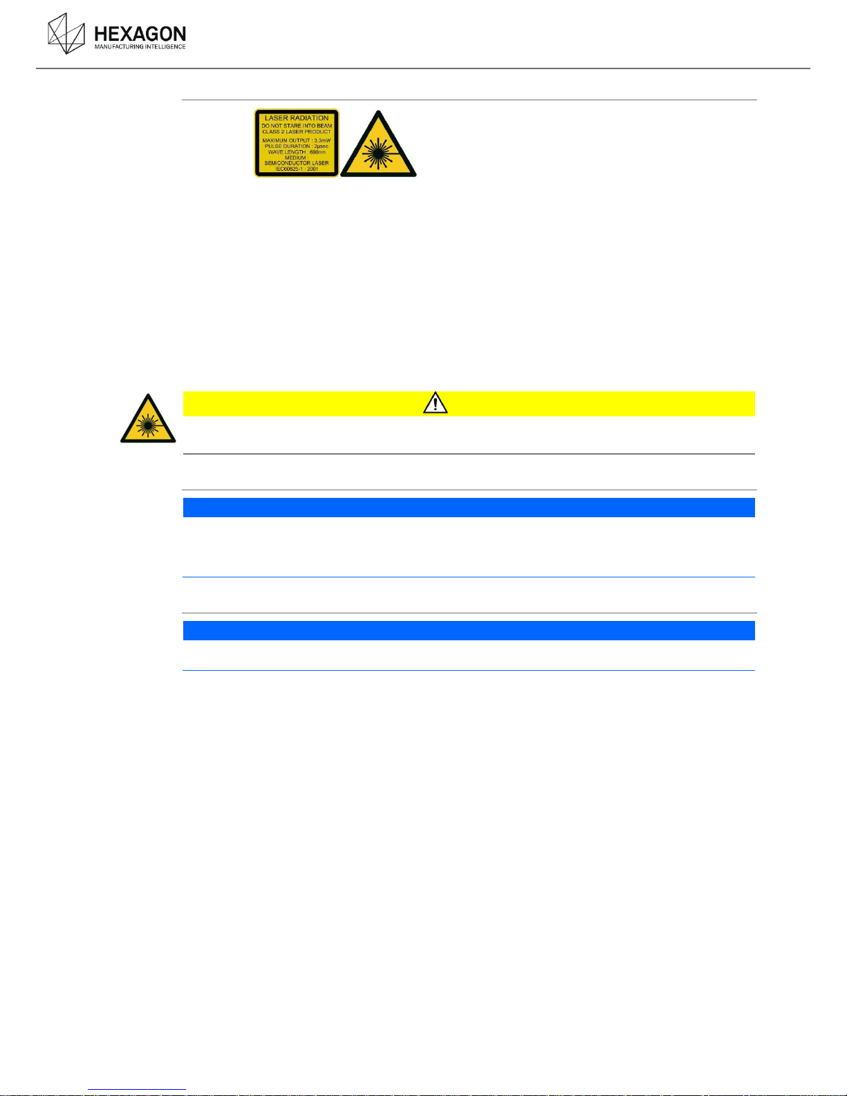
Class 2 laser product according to IEC60825-1. Do not stare into beam directly or indirectly via
mirror-like surfaces.
High precision instrument – avoid drops or impact damage to prevent accuracy and sensitivity
degradation.
Avoid attaching/detaching electrical connectors when controller is powered up.
Do not touch the optical windows on the front cover.
Do not use solvents to clean the sensor case.
Do not cover the air inlet and output vent of the controller unit.
Ensure adequate electrical grounding of the controller.
Avoid storage at high temperatures, for example, in a car in hot weather
Avoid circumstances leading to condensation e.g. rapid changes of temperature as deposits on
the optical elements may render the unit inoperable and invalidate warranty
No user serviceable parts – opening the sensor or controller invalidates warranty
CAUTION
Laser Guide Product Class 2M: Risk of eye injury!
Do not stare into laser guide beam or view directly with optical instruments at less than 100mm.
TKJ26 connector protection
NOTICE
When the scanner is mounted on an arm equipped with a TKJ13 probe connector, a protection
sticker (provided with the scanner) must be placed on the connector of the scanner.
Any deterioration due to the use of the scanner on a TKJ13 without the protection will avoid the
guaranty.
Prerequisites
NOTICE
The use of the scanner requires a minimum configuration. Read the Prerequisite chapter before
any setup of the scanner onto the arm.
Page 6

Description
HP-L-8.9 T2 Scanner user manual V1.1.0 (08/06/2016) 6
CONTENT
INTRODUCTION ...................................................................................................................... 3
IMPORTANT SAFETY NOTE ................................................................................................... 4
CONTENT ................................................................................................................................. 6
A. Description ................................................................................................................ 7
B. Scanner Setup ......................................................................................................... 10
Prerequisites - Setup the arm ....................................................................................... 10 B.1
Mount the Scanner on the arm ..................................................................................... 11 B.2
Connection of the scanner ............................................................................................ 12 B.3
Power-On / Warm-up / Status LED .............................................................................. 14 B.4
C. Operating ................................................................................................................. 15
First time installation ..................................................................................................... 15 C.1
Scanning Widget........................................................................................................... 16 C.2
RDS Settings ................................................................................................................ 17 C.3
Adjustment of the exposure ............................................................................. 18 C.3.1
How to handle and digitize ........................................................................................... 19 C.4
How to start and stop ....................................................................................... 20 C.4.1
Working Distance LED ..................................................................................... 21 C.4.2
Speed ............................................................................................................... 22 C.4.3
Camera orientations ......................................................................................... 22 C.4.4
Calibrate the scanner ................................................................................................... 25 C.5
Read Manuals ............................................................................................................... 28 C.6
D. Appendix ................................................................................................................. 29
Troubleshooting ............................................................................................................ 29 D.1
European Union (and EEA) only recycling ................................................................... 30 D.2
Dimensions ................................................................................................................... 31 D.3
Characteristics of the probe .......................................................................................... 32 D.4
Page 7
Description
HP-L-8.9 T2 Scanner user manual V1.1.0 (08/06/2016) 7
DESCRIPTION
A.
The HP-L-8.9 scanner is designed to be used with all the ROMER Absolute Arms, 6 axes.
The use of the HP-L-8.9 scanner is not possible on a 7 axes arm.
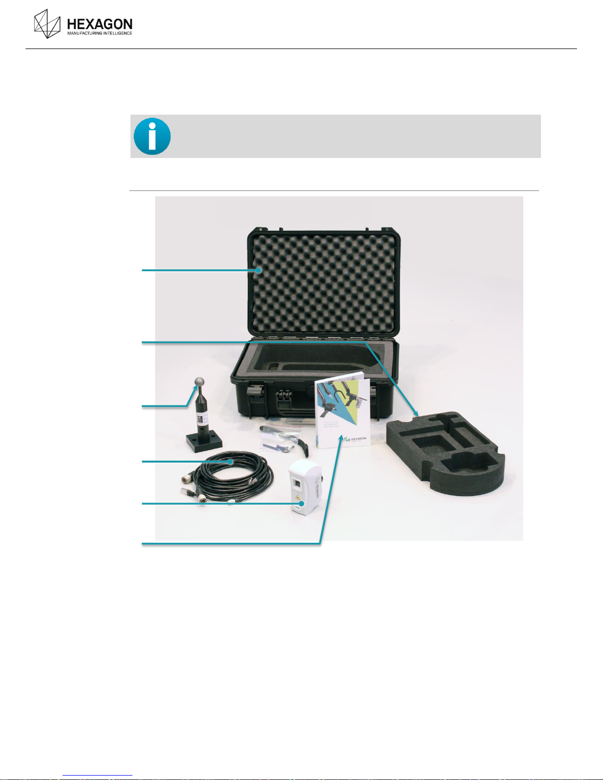
Package content
a. Carrying case
b. Top foam of the case
c. Calibration artefact
d. Connection cables
e. HP-L-8.9 scanner
f. Installation Stick and Quick Installation guide
a
b
c
d
e
f
Page 8
Description
HP-L-8.9 T2 Scanner user manual V1.1.0 (08/06/2016) 8
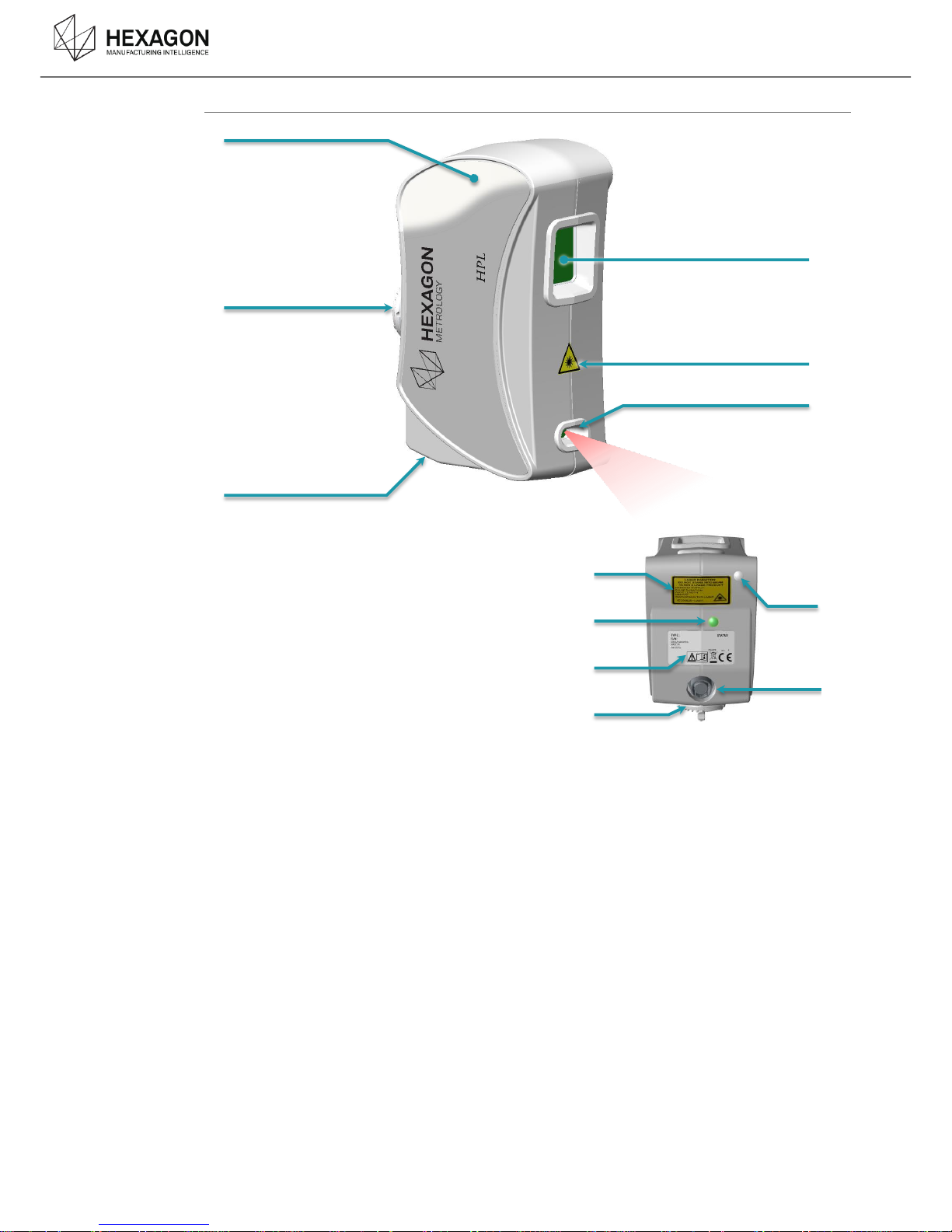
Scanner description
a. Stand-off colour guide
b. TKJ connector
c. Scanner cable connector
d. Scanner camera
e. Laser warning sticker
f. Laser emitter
g. laser warning
h. Status LED
i. Identification sticker
j. Ambient light sensor
The HP-L-8.9 scanner is a portable 3D laser scanner dedicated for Romer Absolute Arms. A laser
line emitted from the bottom of the scanner is projected onto the surface, giving a laser stripe that
is caught by the scanner camera sensor. This stripe is the 3D shape of the part, and by moving the
scanner over the surface, the system can return a cloud of points of the part that has been
digitized.
a
b
c
g
h
i
b
d
e
f
j
c
Page 9
Description
HP-L-8.9 T2 Scanner user manual V1.1.0 (08/06/2016) 9
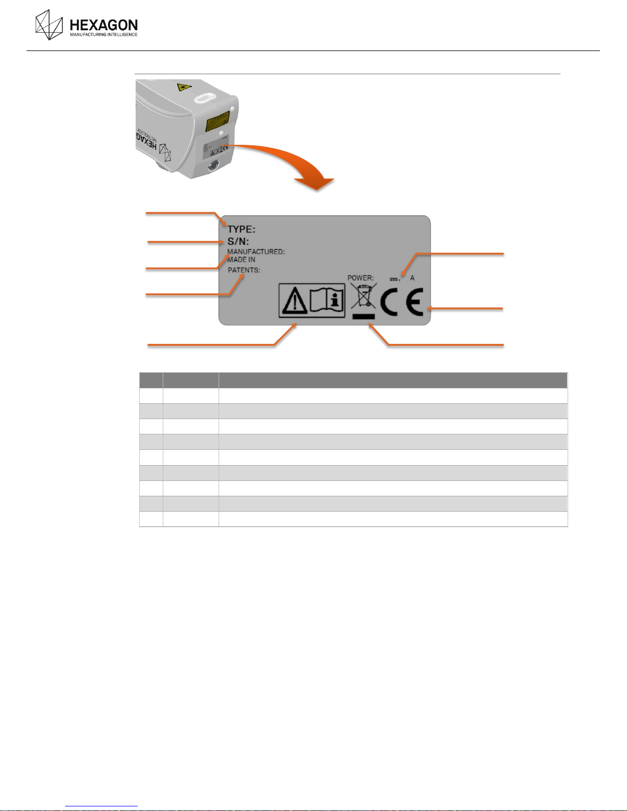
Identification
N°
Item
Description
a
Type
Shows the type of scanner : HP-L-8.9
b
S/N
Serial number :
c
Date
Date of manufacture of the Scanner
Made in
Country of the factory
d
Patents
e Manual
Recommendation to read the manual.
f
Power
Power consumption
g
CE
Product conformity
h
Recycling
European recycling (see Appendix)
f
g
h
a
b
c
d
e
Page 10
Scanner Setup
HP-L-8.9 T2 Scanner user manual V1.1.0 (08/06/2016) 10
SCANNER SETUP
B.
PREREQUISITES - SETUP THE ARM B.1
Before any operation on your 3D scanner, please ensure that all the requirements are respected:
Driver
RDS 4.1.0 or later
Computer plugs
1 Ethernet gigabit adapter
Arm Feature Pack
Scanning Pack, or Mobility Pack.
For all Absolute Arms 71xx or 73xx, not equipped with a Feature Pack by
default, at least a Scanning Pack has to be added.
Arm setup
Proceed to all the necessary steps to setup, connect and start the arm.
Refer to the user manual of the arm for detailed instruction.
Mother Board
Firmware
Version 2.10 or upper
Event board
firmware
Version 126 or upper
PIC firmware
Version 9 or upper recommended
Armspecs
The armspecs needs to be updated for the following arms :
Arm “FA” before 7xxx-1870-FA
Arm “UC” before 7xxx-2472-FA
(Contact your local Service Centre)
NOTICE
The Feature Pack FP4 (HP-LC-200, dedicated to the HP-L-20.8) is not compatible with the use
of the HP-L-8.9.
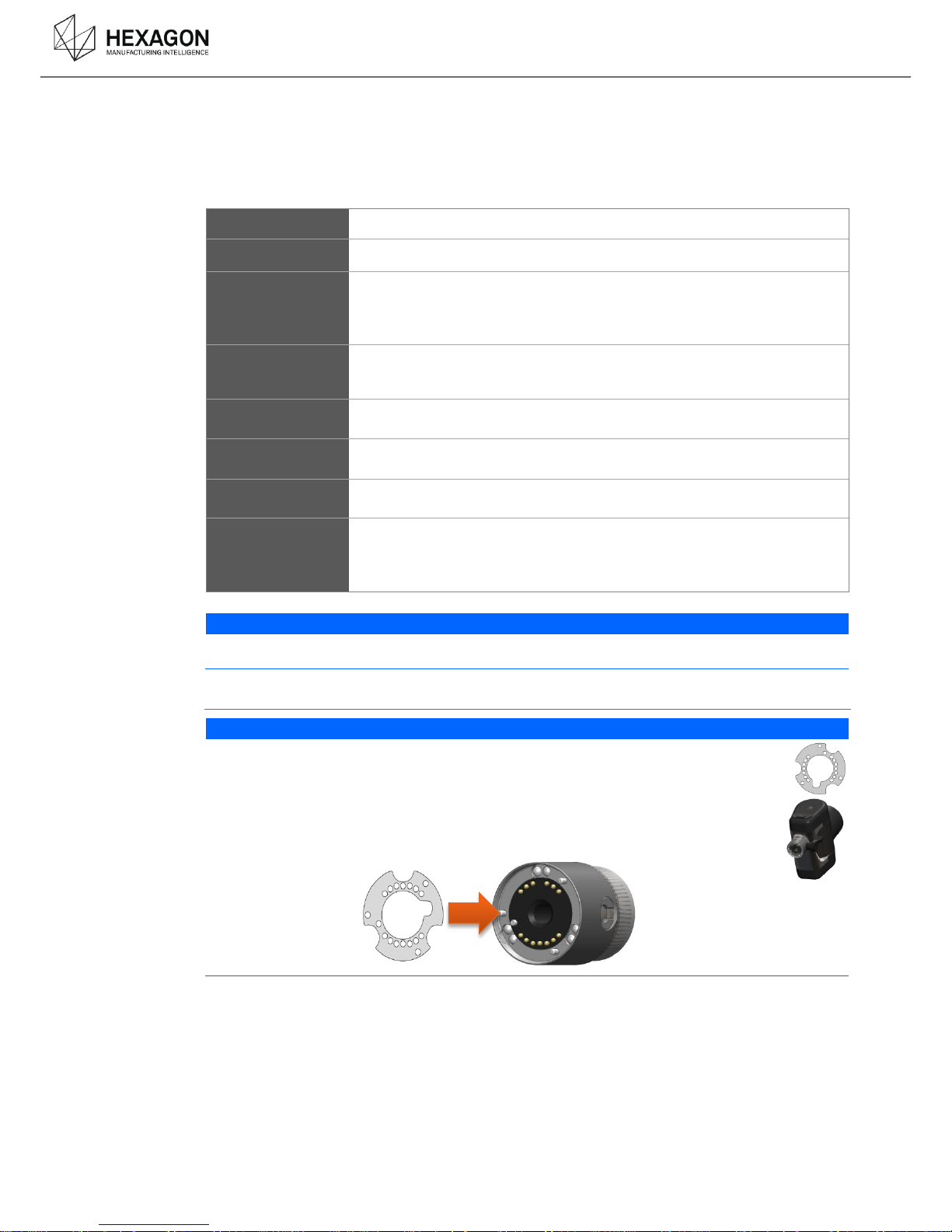
TKJ26 connector protection
NOTICE
When the scanner is mounted on an arm equipped with a TKJ13 probe connector (old
wrist), a protection sticker (provided with the scanner) must be placed on the connector
of the scanner.
Any deterioration due to the use of the scanner on a TKJ13 without the protection will
avoid the guaranty.
The protection is auto-adhesive : simply paste it on the Female connector, fitting the
protection holes to the pins of the connector.
Page 11
Scanner Setup
HP-L-8.9 T2 Scanner user manual V1.1.0 (08/06/2016) 11
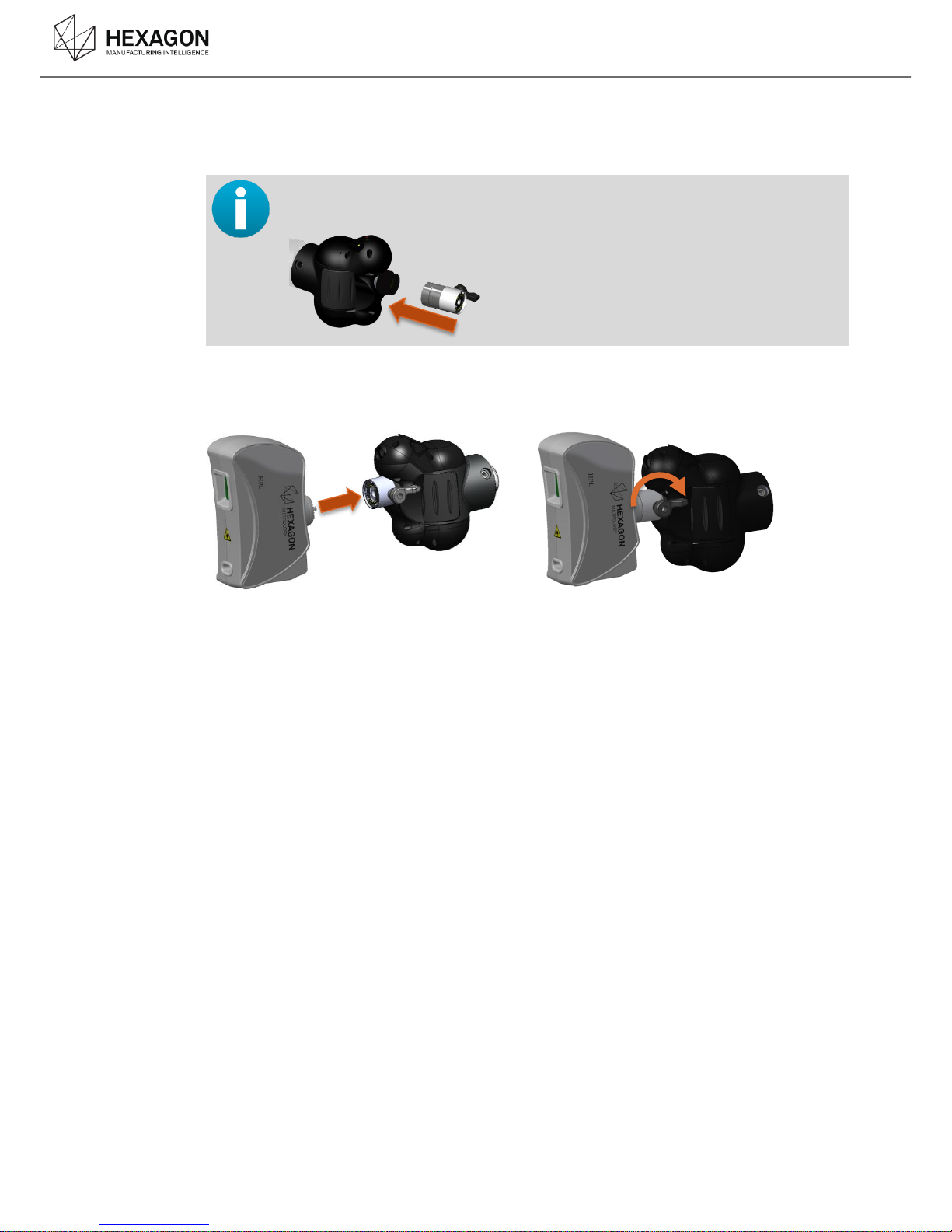
MOUNT THE SCANNER ON THE ARM B.2
The HP-L-8.9 is mounted on a 6axes arm through its TKJ female connector.
71xx series arms
As the 71xx arms are provided with a threaded connector, a TKJ adapter has to be
added to the arm. Refer to the Arm user manual or to the TKJ Adapter user guide.
Install the scanner on the TKJ connector
Lock the connector
Page 12
Scanner Setup
HP-L-8.9 T2 Scanner user manual V1.1.0 (08/06/2016) 12
CONNECTION OF THE SCANNER B.3
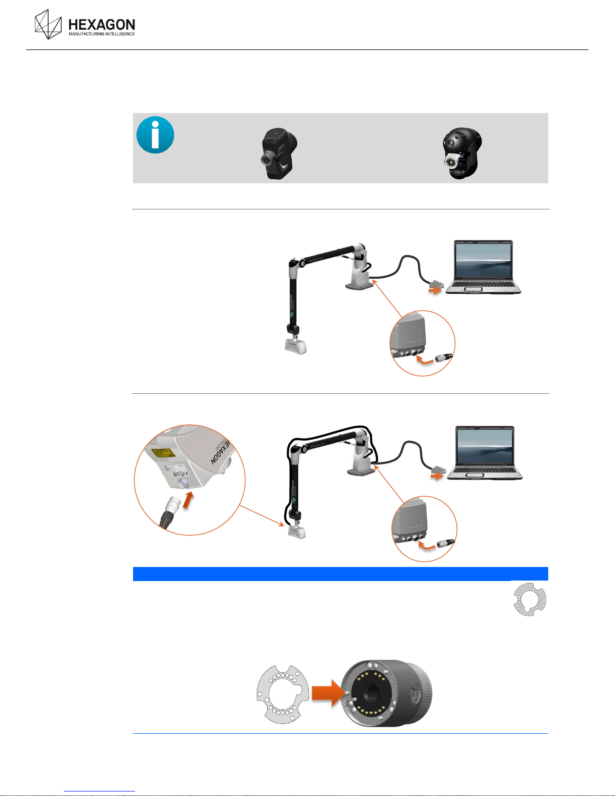
Depending on the TKJ version, the scanner needs or not an external cable
Wrist V1 with TKJ13
Wrist V2 with TKJ26
Standard wire (TKJ26)
To connect the scanner, simply connect the scanner cable from the Feature Pack to the Ethernet
plug of the computer.
External wire (TKJ13)
In case of mounting on a TKJ13 (wrist version1), added to the Ethernet plugging, an external cable
has to be plugged onto the scanner itself.
NOTICE
When the scanner is mounted on an arm equipped with a TKJ13 probe connector, a
protection sticker (provided with the scanner) must be placed on the connector of the
scanner.
Any deterioration due to the use of the scanner on a TKJ13 without the protection will
avoid the guaranty.
The protection is auto-adhesive : simply paste it on the Female connector, fitting the protection
holes to the pins of the connector.
Page 13
Scanner Setup
HP-L-8.9 T2 Scanner user manual V1.1.0 (08/06/2016) 13
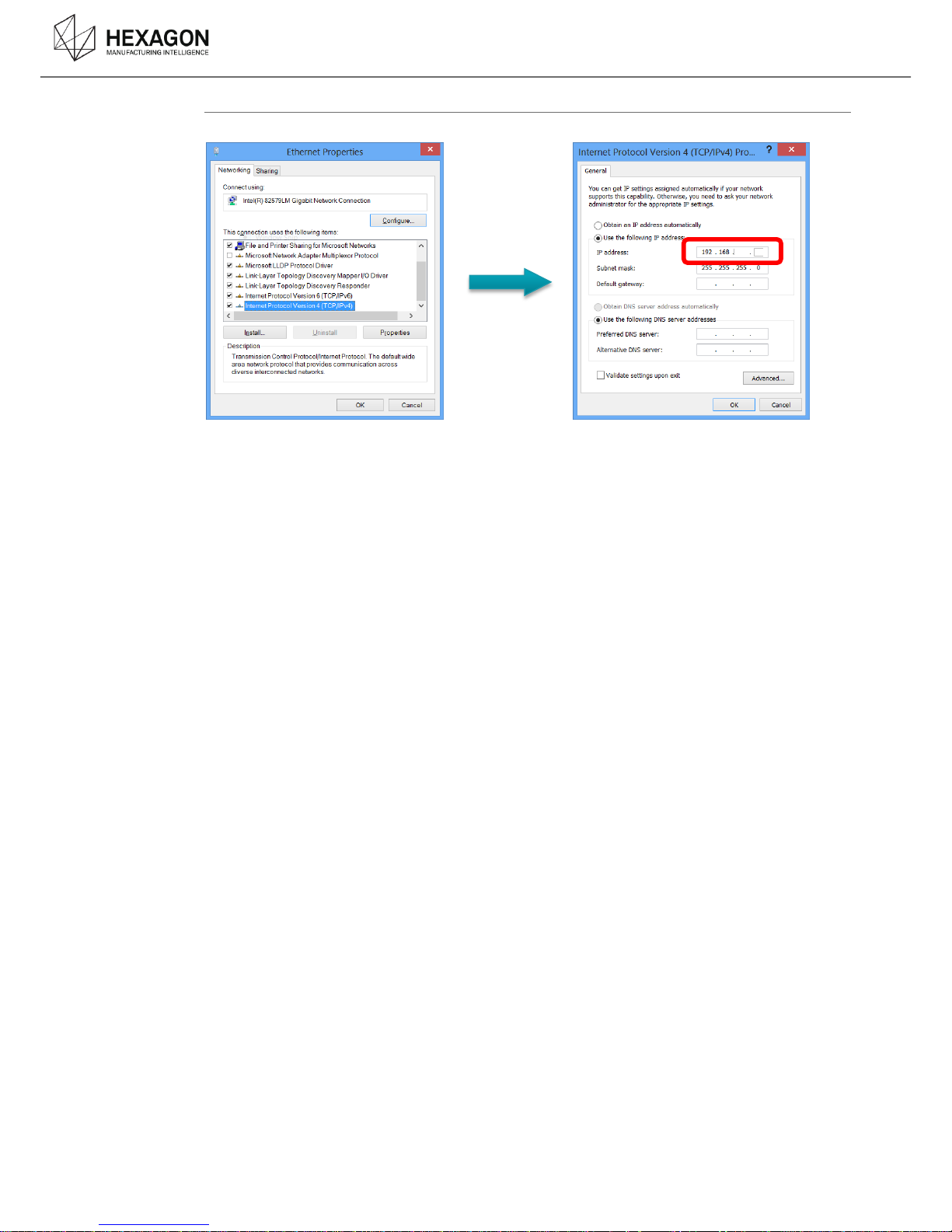
Computer Setup :
Setup on-board Ethernet port as 192.168.178.1 (controller @ = 192.168.178.200)
Page 14
Scanner Setup
HP-L-8.9 T2 Scanner user manual V1.1.0 (08/06/2016) 14
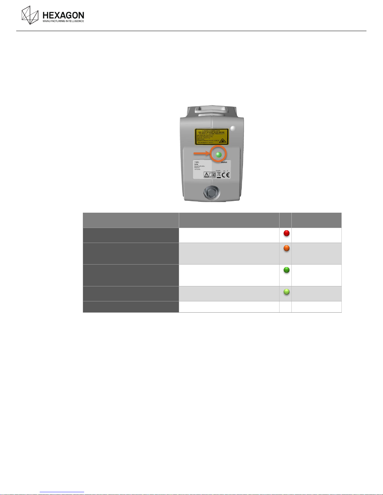
POWER-ON / WARM-UP / STATUS LED B.4
The scanner is powered by the arm itself, simply switch on the arm.
Once the whole system is installed, connected and powered, to ensure the quality of the digitizing,
a warm-up time of 5mn minimum (15mn recommended) is necessary before any scanning
operation.
Item
Attribute
User indicator
(colour code)
Boot time
(time until factory mode ready)
2 seconds
RED
Boot time
(time until application mode
ready)
7 seconds
Orange
System ready time
(time when measuring can start
via SDK)
20 seconds
(depends on Windows network
connection)
Green flashing
Warm-up time
(time to reach 90% accuracy)
5 minutes
Green fixed
Sensor fault indicator
(remaining colour options /flashing)
Page 15

Operating
HP-L-8.9 T2 Scanner user manual V1.1.0 (08/06/2016) 15
OPERATING
C.
NOTICE
A warm-up time of 5mn is required (15mn recommended) before any usage of the scanner.
NOTICE
When used with a Mobility Pack (FP2), the arm needs to be on power supply. The HP-L-8.9
cannot be used on battery
FIRST TIME INSTALLATION C.1
For the first time the scanner is mounted on the arm, RDS recognises it, asks for scanner
calibration.
(See further for the calibration details).
Page 16
Operating
HP-L-8.9 T2 Scanner user manual V1.1.0 (08/06/2016) 16
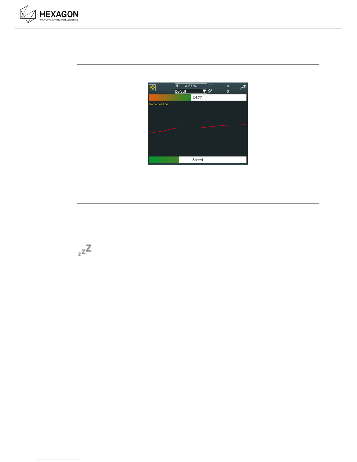
SCANNING WIDGET C.2
Description
When using a HP-L scanner on a ROMER Absolute Arm managed by RDS, a window appears, to
help scanning.
When scanning, a sound also gives indication about the distance to the object.
For more information about this widget, please refer to RDS User Manual.
Laser Power
For security reasons, the laser is automatically powered off under these conditions:
after some seconds of no use
when the arm is left in the rest position
as soon as the digitizing menu is left
Then the capture status icon shows the following symbol in the RDS widget.
Page 17
Operating
HP-L-8.9 T2 Scanner user manual V1.1.0 (08/06/2016) 17
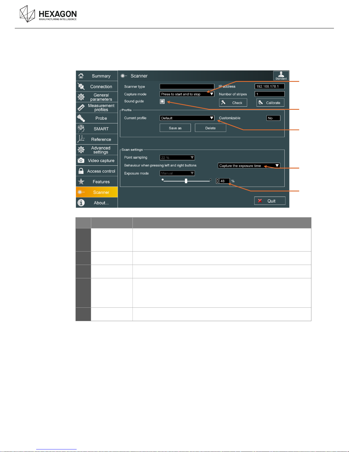
RDS SETTINGS C.3
In RDS Control Panel, the scanner’s settings can be controlled: access to RDS Control Panel, then
select “Scanner’s Tab.
Setting
Description
a
Capture mode
Defines the way to use the button :
capture only when BP1 is pressed
start or stop capture when BP1 is pressed
b
Depth sound
Emits a sound that helps to keep good distance from the part.
c
Profile
Gives the possibility to save the current settings into a scanning profile
d
Behaviour of
the buttons
Action done when pressing simultaneously the left (BP0) and right (BP1)
buttons of the arm
None (default) : no action
Capture the exposure (see further)
e
Exposure
Manual adjustment of the exposure
a
b
e
d
c
Page 18
Operating
HP-L-8.9 T2 Scanner user manual V1.1.0 (08/06/2016) 18
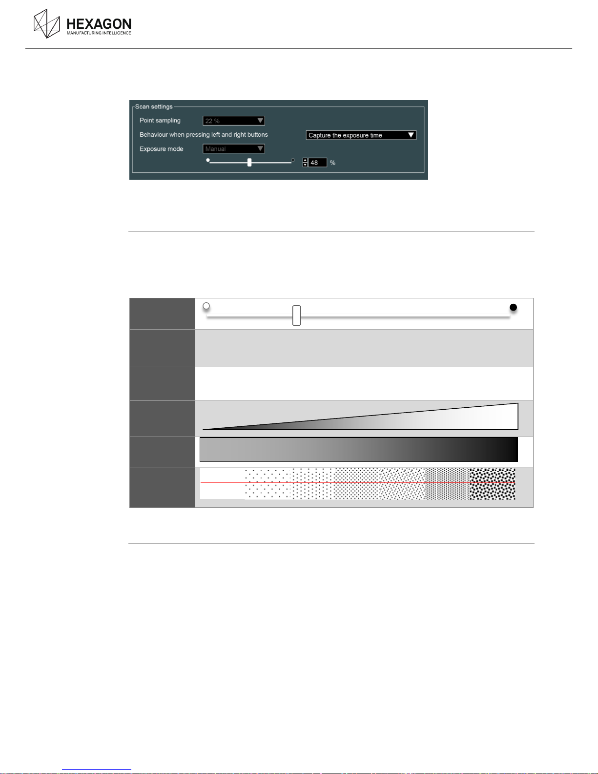
ADJUSTMENT OF THE EXPOSURE
C.3.1
2 ways to setup the exposure are available:
Manual setup
Set up the exposure time of the camera: the higher the value is, the longer the camera is opened.
This parameter has to be set up according to the ambiance light and the darkness of the surface:
set low value for clear surface and higher value for dark surface. However, a high value increases
the risk of noise points. It is then necessary to adjust this parameter correctly.
Cursor
Percentage
1% 25% 50% 75% 100%
Exp. time
20µs 200µs 1000µs 4000µs 10000µs
Light capted
by the
scanner
Darkness of
the part
Noise
Auto Static SetUp (Capture the exposure)
It is possible to setup automatically the exposure through a static capture.
In RDS Control Panel, Scanner tab, set the “Behaviour” to capture exposure time
Place the scanner over the surface and press simultaneously BP0 and BP2 : the exposure mode
switches temporarily to automatic mode until the adjustment is done. Hold the scanner a few
seconds until the arm emits 2 beeps (the mode automatically switches back to manual mode).
Scan can then go on.
Page 19
Operating
HP-L-8.9 T2 Scanner user manual V1.1.0 (08/06/2016) 19
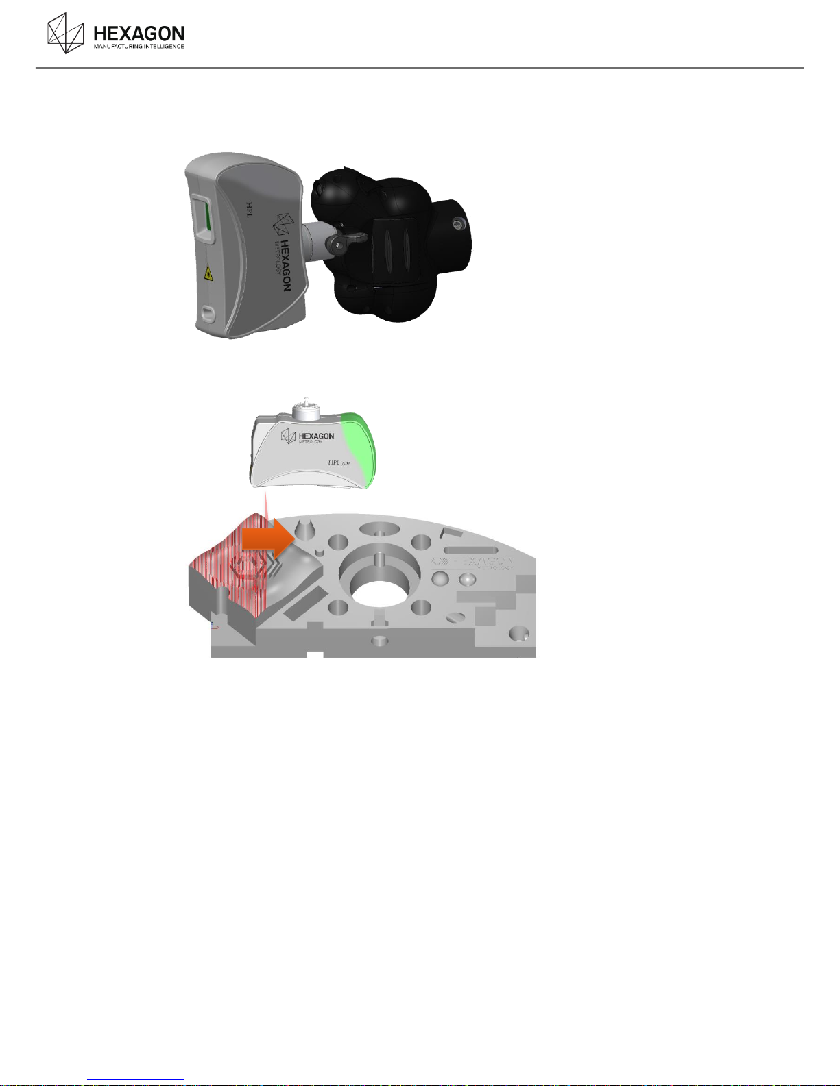
HOW TO HANDLE AND DIGITIZE C.4
The HP-L-8.9 is designed to be mounted and used on a 6 axis Romer Absolute arm. Thus the
operator has to handle the wrist of the arm and not the scanner itself.
.
By holding the wrist of the arm, place the scanner over the surface to digitize, at a correct distance,
in order to get green or at least blue or yellow light on the scanner (see “Working distance”). Then
move the scanner over the surface with a translation movement as a spray gun.
Page 20
Operating
HP-L-8.9 T2 Scanner user manual V1.1.0 (08/06/2016) 20
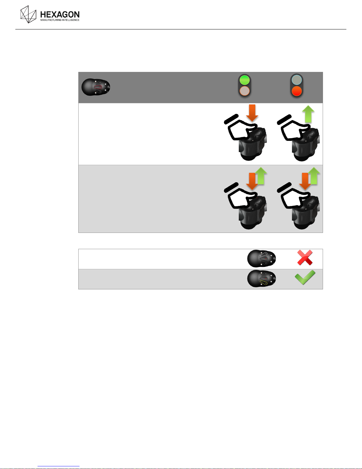
HOW TO START AND STOP C.4.1
Button 1 can be configured in one of two ways (see RDS settings in RDS Control Panel):
Press to start and press again to stop scanning.
Press and hold to scan
Then (depending on software)
Press button 0 to cancel last stripe or scan patch
Press button 2 to finish the scan
Page 21
Operating
HP-L-8.9 T2 Scanner user manual V1.1.0 (08/06/2016) 21
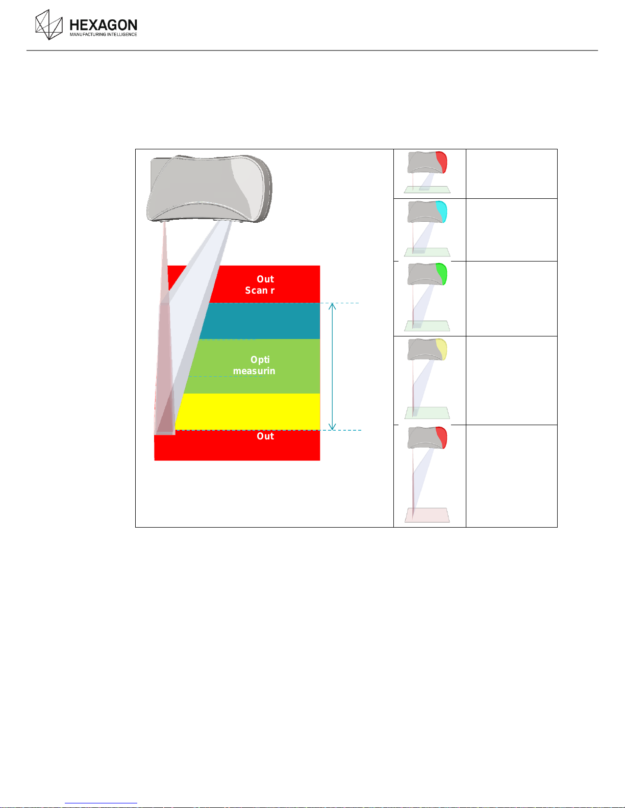
WORKING DISTANCE LED C.4.2
To indicate to the user the best working distance, RGB LED easily visible by user are integrated at
the scanner.
To help the user, the scanner displays a light depending on the distance:
Scan out of range
– too close
Inside scanning
range - Low
Inside scanning
range – Optimum
range
Inside scanning
range - High
Scan out of range
– too far
Optimum
measuring range
Out of
Scan range
Maximum
Scan
range
Out of
Scan range
Page 22
Operating
HP-L-8.9 T2 Scanner user manual V1.1.0 (08/06/2016) 22
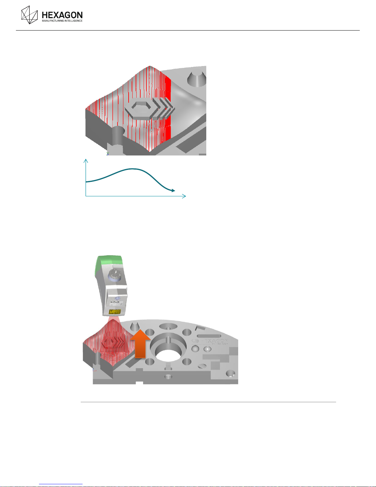
SPEED C.4.3
Depending on the speed of movement, more or less points and details may be caught. The faster
the speed is, the lower the density of stripes will be.
CAMERA ORIENTATIONS C.4.4
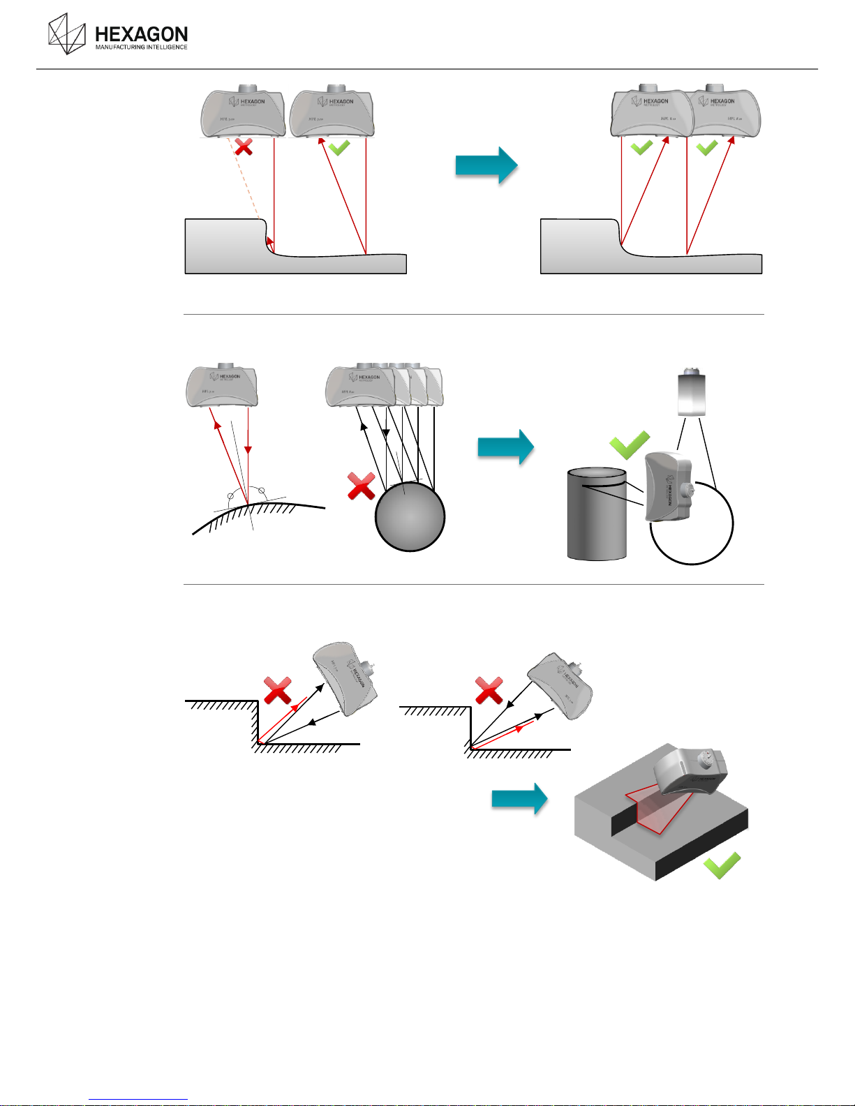
For any scanner, it is recommended to keep the laser perpendicular to the surface.
Pay attention to orientate correctly the scanner in order to get all the necessary detail. A cross
movement may be useful in some cases
Shadow fields
As there is an angle between the laser plane and the camera, depending on the relief, there can be
areas where the object shadows the camera view. To get points in those areas, simply re-orientate
the scanner and continue.
Movement speed
Page 23
Operating
HP-L-8.9 T2 Scanner user manual V1.1.0 (08/06/2016) 23
Total Reflection
Mirror-like surfaces can cause a direct reflection from the laser to the camera; avoid these
problems through careful orientation of the sensor as show below.
Secondary Reflection
Secondary reflections can occur on reflective, concave surfaces; avoid these problems through
careful orientation of the sensor as show below.
Page 24
Operating
HP-L-8.9 T2 Scanner user manual V1.1.0 (08/06/2016) 24
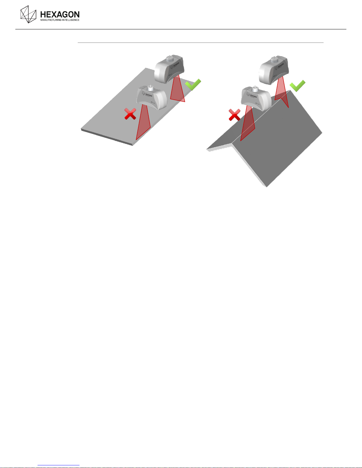
Edges
When measuring an edge, orientate the laser at 90 degrees to the feature as shown.
Page 25
Operating
HP-L-8.9 T2 Scanner user manual V1.1.0 (08/06/2016) 25
CALIBRATE THE SCANNER C.5
For the first time the scanner is mounted, the scanner calibration is required. Once done, the
calibration process is no more necessary.
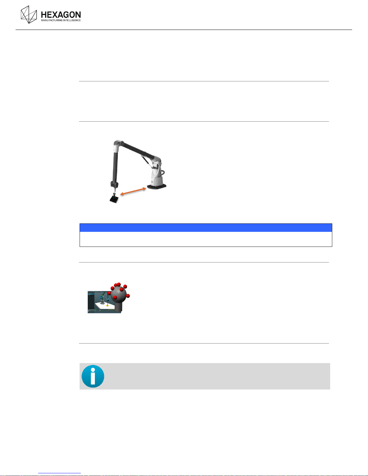
Run the calibration
Once the scanner is detected, RDS proposes to run the calibration. Select the script “Sphere with
reference method”. To recalibrate an existing scanner, in RDS Menu, select “Calibrate current
probe”.
Artefact Properties
1. The calibration sphere that has to be used should be placed at 50% of the measurement
volume.
2. When prompted, enter the diameter value
NOTICE
Do not use other artefact sphere than the provided one; it has been designed to give optimal
results.
Reference Sphere
3. Insert 15mm Ref Probe
4. Take 9 points on sphere with 15mm probe
5. Check reference sphere results and “OK”
Use Scanner
6. Mount the scanner to calibrate.
For the scanner calibration, no need to adjust the exposure : a specific scanning
profile is automatically selected for the calibration sphere.
Page 26
Operating
HP-L-8.9 T2 Scanner user manual V1.1.0 (08/06/2016) 26
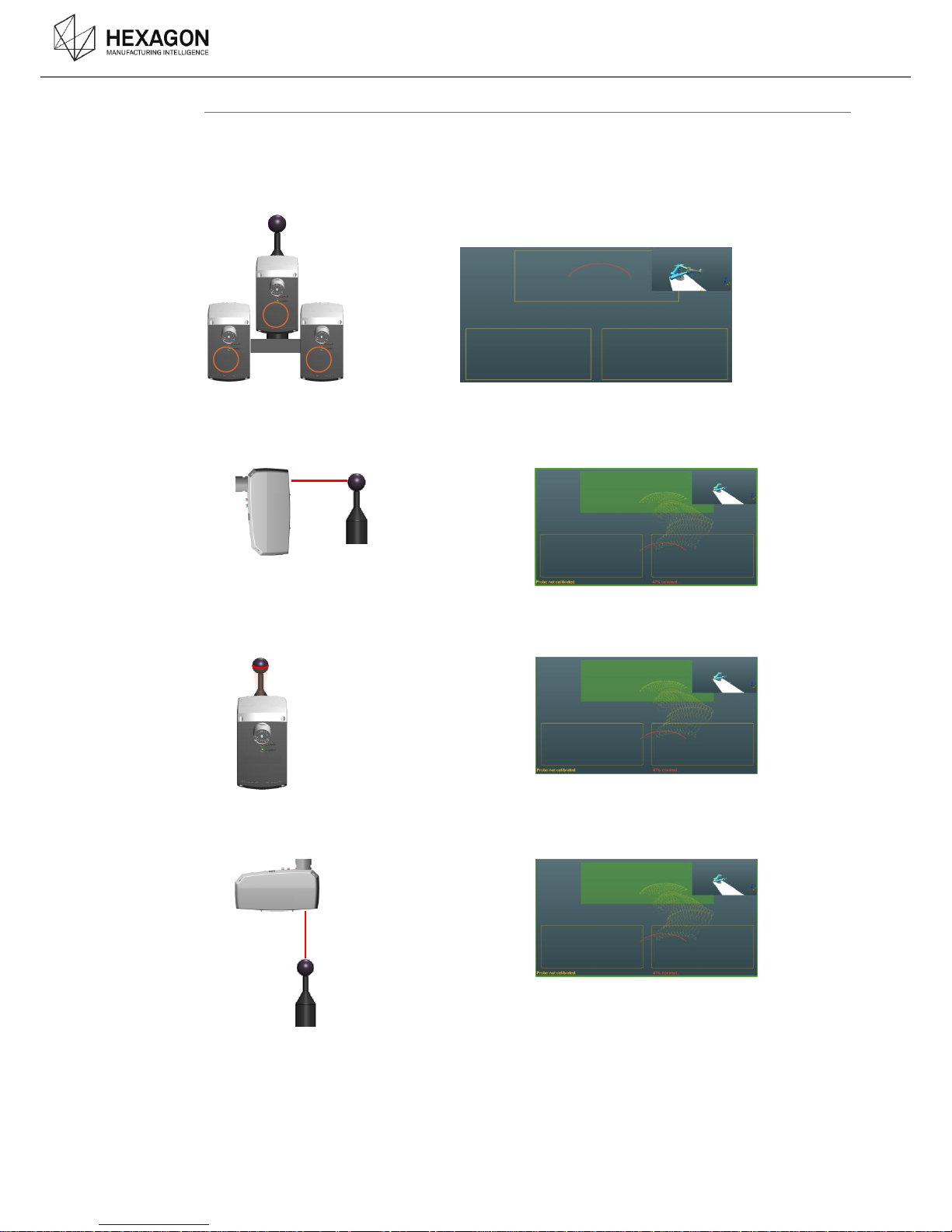
Field measurement
For each of the 3 orientations of the scanner, scan the sphere in order to cover the 3 target
squares:
1 near centred position (#1)
1 far left position (#2)
1 far right position (#3).
7. Position the scanner horizontally, at 0°, and scan, covering the 3 target squares.
Validate by pressing stopping the scan (right button).
8. Position the scanner horizontally, at 90°, and scan, covering the 3 target squares.
Validate by pressing stopping the scan (right button).
9. Position the scanner vertically, at 0°, and scan, covering the 3 target squares.
Validate by pressing stopping the scan (right button).
Page 27
Operating
HP-L-8.9 T2 Scanner user manual V1.1.0 (08/06/2016) 27
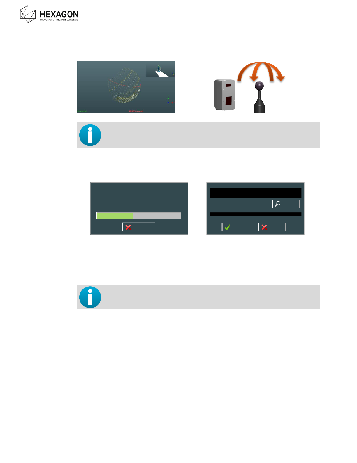
Global sphere measurement
Digitize the whole sphere with the scanner: wait for the 100 % coverage at least to stop digitizing.
Validate by pressing on BP2 (right button).
It is still possible to continue scanning even once the covered is completed, to
enhance the quality of calibration, however, the calculation may be longer.
Calculation
After all the measurements, the calculation automatically starts.
At the end of calculation, click on yes.
Verification
10. To validate the calibration, please perform the laser scanner accuracy test : digitize the sphere
,then stop and check the results.
For more details, please refer to RDS Data Collector manual.
Probe calibration is finished.
Residual deviation=0.019797
Do you wish to use calculated calibration ?
Please wait.
Step=9, Residual error=0.019797, Improvement=0.005339%
Cancel
Yes
No
Report
Page 28

Operating
HP-L-8.9 T2 Scanner user manual V1.1.0 (08/06/2016) 28
READ MANUALS C.6
For more detailed information, please read the following manuals:
Connection, arm manipulation
ROMER Absolute Arm manual
H00002006
How to setup the probe
RDS User manual
H00002007
How to calibrate and check the probe
RDS Data Collector manual
H00002008
Page 29

Appendix
HP-L-8.9 T2 Scanner user manual V1.1.0 (08/06/2016) 29
APPENDIX
D.
TROUBLESHOOTING D.1
Issue
Operation
Connection
The status in the scanning window
always shows “Initialization : Waiting
for camera”
Check the IP address of the computer :
192.168.178.x
Check that the arm is on power supply, not on
battery.
Check that all the requirements are respected
In case of a Wrist V1 (with TKJ13), check that the
external cable is correctly plugged on the scanner.
Page 30

Appendix
HP-L-8.9 T2 Scanner user manual V1.1.0 (08/06/2016) 30
EUROPEAN UNION (AND EEA) ONLY RECYCLING D.2
This symbol indicates that this product is not to be disposed of with household waste, according to
the WEEE Directive (2002/96/EC) and national law. This product should be handed over to a
designated collection point, e.g., on an authorised one-for-one basis when buying a new similar
product or to an authorised collection site for recycling waste electrical and electronic equipment
(EEE).
Improper handling of this type of waste could have a possible negative impact on the environment
and human health due to potentially hazardous substance that are generally associated with EEE.
At the same time, cooperation in the correct disposal of this product will contribute to the effective
usage of natural resources. For more information about where to drop off waste equipment for
recycling, please contact the local city office, waste authority, approved WEEE scheme or
household waste disposal service.
(EEE: Norway, Iceland and Liechtenstein)
Page 31
Appendix
HP-L-8.9 T2 Scanner user manual V1.1.0 (08/06/2016) 31
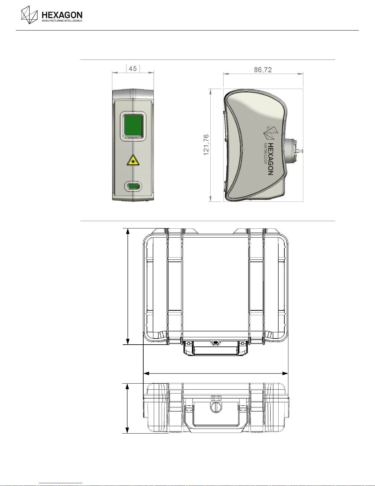
DIMENSIONS D.3
Sensor
Case
336
300
148
Page 32

Appendix
HP-L-8.9 T2 Scanner user manual V1.1.0 (08/06/2016) 32
CHARACTERISTICS OF THE PROBE D.4
Standard
EN 60825-1 : 2007
class
2M
Wave length
650nm
Line width (mid field)
80 mm (min 65 / max 98)
Point acquisition rate
45 000 points / sec
Points per line
750
Line rate
60 Hz
Min Point spacing
0.08 mm
Stand off
135 mm ± 45mm
Warm up time
< 10 min
Laser power adjustment
Semi-automatic
Output power
< 1mW
Admission angle
60° fan angle
Operating Temperature
5°C to +40°C (32°F – 122°F)(open double check)
Storage Temperature
-30°C to +70°C
Altitude
up to 3500m
Vibration in transport
case
According to ISO 9022-3:1998
Humidity
maximum 95% non-condensing
IP Rating
IP 50
Weight
322 g
2 sigma accuracy
0.040 mm
Regulatory
CE compliance: conformance with CEM directive 2004/108/EC and low voltage directive
2006/95/EC
Harmonized Norm: EN 61326-1:2006
Laser Safety: conformance with IEC 60825-1:2007 and CDRH standards.
Compliant with directive RoHS 2 (directive 2011/65/EU)
Page 33

 Loading...