

Hewlett Packard Enterprise StoreEver ESL G3 Installation Instructions Manual

StoreEver ESL G3 Tape
Library
CAUTION: Parts can be damaged by
electrostatic discharge. Keep parts in their
containers until needed. Make sure that you
are properly grounded when touching static
sensitive components.
NOTE: ESL G3 firmware version 665H or
later is required to support the HDEM
Barcode Scanner. If necessary, upgrade the
library firmware before installing the scanner
hardware.
High Density Expansion
Module Barcode Scanner
Installation Instructions
Abstract
This document describes how to install a barcode
scanner in a High Density Expansion Module (HDEM)
in an ESL G3 Tape Library.
NOTE: The bolts connecting the HDEM to
the adjacent module must be attached so
that the bolts on the rear of the HDEM are
placed with the bolt heads inside the HDEM.
Installing the bolts incorrectly (bolt heads
outside the HDEM) will cause the nut and
bolt to interfere with the vertical movement
of the HDEM barcode scanner. If the bolts
are installed in the incorrect fashion (bolt
heads outside the HDEM), remove them one
at a time and retighten. Removing and
replacing one bolt at time prevents the
modules from needing to be disconnected or
re-leveled.
Inspect the contents of the kit
This kit contains:
• one HDEM barcode scanner with ribbon cable
• six 2.5 mm hex screws
© Copyright 2013, 2016 Hewlett Packard Enterprise Development LP
Documentation feedback
Send any errors, suggestions, or comments to Documentation
Feedback (docsfeedback@hpe.com).
Part Number: E3S05-96002
Published: March 2016
Edition: 2
*E3S05-96002*
Preparing the HDEM
1. Vary off the tower by pressing the Robotics
Enabled button on the operator panel on the
rear access door of the HDEM. The LED on
the operator panel will turn amber when the
tower is varied off.
2. Open the rear access door.
Page 1
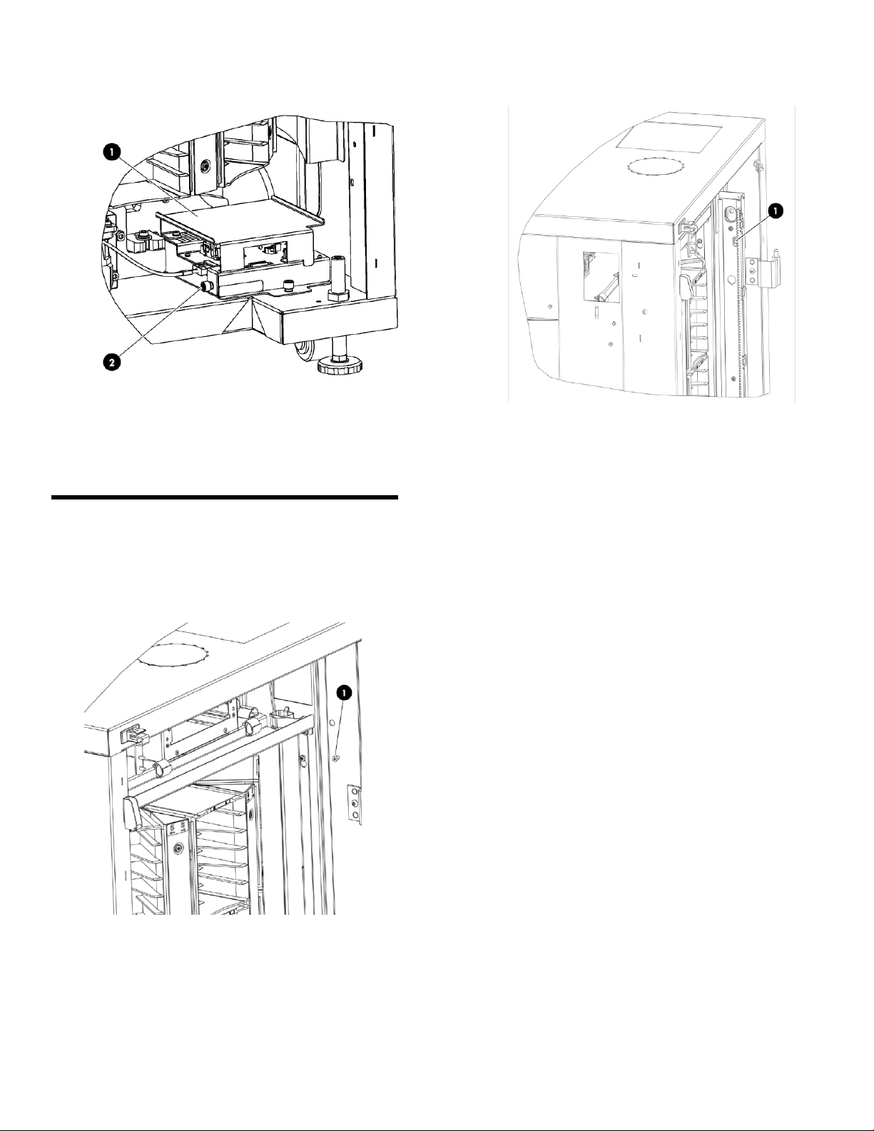
3. Loosen the thumbscrew on the side of the
TWR assembly and remove the TWR shield.
1. TWR shield
2. Thumbscrew
Installing the Barcode Scanner
Required tools: 2.5 mm hex wrench
1. Insert and partially tighten the upper-most 2.5
mm hex screw.
screw. Gently let the barcode scanner hang
from the partially-tightened screw.
1. Keyhole slot
3. Insert and tighten the 2.5 mm hex screw that
is fourth down from the top of the scanner
mounting bracket. Vertically, this screw is at
about the halfway point of the module, close
to the height of the top of the exterior handle.
4. Insert and tighten the bottom-most 2.5 mm hex
screw, located at the bottom-right of the
module, just above the TWR.
5. Insert and tighten the second, third, and fifth
screws (counting from the top down).
1. Top 2.5 mm hex screw
2. Remove the barcode scanner from the
packaging. Slide the upper-most keyhole slot
of the barcode scanner onto the
partially-tightened upper-most 2.5 mm hex
Page 2
 Loading...