

Hewlett Packard Enterprise StoreEver MSL2024, StoreEver MSL4048, StoreEver MSL8048, StoreEver 8096 User's And Service Manual
Page 1

HPE StoreEver MSL2024, MSL4048, MSL8048, and MSL8096 Tape Libraries User and Service Guide
Abstract
This guide provides information on installing, configuring, upgrading, and troubleshooting the tape
library. This guide is intended for system administrators and other users who need physical and
functional knowledge of the tape library.
Part Number: Q6Q62-00024a
Published: February 2018
Edition: 10
Page 2

©
Copyright 2006, 2007, 2010, 2012, 2015, 2018 Hewlett Packard Enterprise Development LP
Notices
The information contained herein is subject to change without notice. The only warranties for Hewlett Packard
Enterprise products and services are set forth in the express warranty statements accompanying such
products and services. Nothing herein should be construed as constituting an additional warranty. Hewlett
Packard Enterprise shall not be liable for technical or editorial errors or omissions contained herein.
Confidential computer software. Valid license from Hewlett Packard Enterprise required for possession, use,
or copying. Consistent with FAR 12.211 and 12.212, Commercial Computer Software, Computer Software
Documentation, and Technical Data for Commercial Items are licensed to the U.S. Government under
vendor's standard commercial license.
Links to third-party websites take you outside the Hewlett Packard Enterprise website. Hewlett Packard
Enterprise has no control over and is not responsible for information outside the Hewlett Packard Enterprise
website.
Acknowledgments
Intel®, Itanium®, Pentium®, Intel Inside®, and the Intel Inside logo are trademarks of Intel Corporation in the
United States and other countries.
Microsoft® and Windows® are either registered trademarks or trademarks of Microsoft Corporation in the
United States and/or other countries.
Adobe® and Acrobat® are trademarks of Adobe Systems Incorporated.
Java® and Oracle® are registered trademarks of Oracle and/or its affiliates.
UNIX® is a registered trademark of The Open Group.
Page 3

Contents
Features........................................................................................................9
MSL2024 front panel........................................................................................................................... 9
MSL4048 front panel......................................................................................................................... 10
MSL8048 and MSL8096 front panel.................................................................................................. 11
MSL2024 back panel.........................................................................................................................12
MSL4048 back panel.........................................................................................................................13
MSL8048 and MSL8096 back panel................................................................................................. 13
Power supply back panel (MSL4048, MSL8048 and MSL8096) ......................................................14
Controller health status indicator.......................................................................................................14
Tape drive back panels......................................................................................................................15
Tape drive power indicator......................................................................................................16
Library options ..................................................................................................................................16
Redundant power supply........................................................................................................17
HPE StoreEver 1/8 G2 Tape Autoloader and MSL Tape Libraries Encryption Kit ................. 17
Command View TL TapeAssure............................................................................................. 17
LTFS Support..........................................................................................................................18
MSL8048 upgrade license......................................................................................................18
HPE MSL Library Extender.....................................................................................................18
Hardware-based encryption ............................................................................................................. 20
KMIP-based key servers.........................................................................................................20
Application-managed encryption............................................................................................ 21
Logical libraries..................................................................................................................................21
MSL2024 and MSL8048 Tape Libraries partitions..................................................................22
MSL4048 and MSL8096 Tape Libraries partitions..................................................................22
Control path and data path failover................................................................................................... 24
Installing the tape library.......................................................................... 25
Location requirements.......................................................................................................................25
FC connection information.................................................................................................................27
SAS connection information.............................................................................................................. 28
Parallel SCSI configuration information.............................................................................................29
Preparing the host............................................................................................................................. 32
Unpacking the shipping container..................................................................................................... 33
Removing the shipping lock ..............................................................................................................33
Installing the library in a rack ............................................................................................................34
Installing the tabletop conversion kit..................................................................................................36
Installing tape drives..........................................................................................................................37
Installing a redundant power supply..................................................................................................39
Changing the SCSI address (parallel SCSI drives only)................................................................... 39
Connecting the FC cable...................................................................................................................40
Connecting the SAS cable.................................................................................................................40
Connecting the parallel SCSI cable...................................................................................................41
Powering on the library .....................................................................................................................42
Configuring the library ...................................................................................................................... 42
Recommended FC interface configuration............................................................................. 43
Verifying the connection.................................................................................................................... 44
Labeling the tape cartridges.............................................................................................................. 44
Verifying the installation.....................................................................................................................45
Downloading product firmware............................................................................................... 45
Contents 3
Page 4

Configuring additional features..........................................................................................................46
Tape cartridges and magazines................................................................47
Tape cartridges.................................................................................................................................. 47
LTO-7 Type M media for LTO-8 drives....................................................................................47
Recommended practices for using and maintaining tape cartridges...................................... 47
Recommended practices for labeling tape cartridges.............................................................48
Write-protecting data cartridges..............................................................................................49
Read and write compatibility...................................................................................................50
Supported media.................................................................................................................... 51
Magazines......................................................................................................................................... 52
MSL2024 magazine slot numbering....................................................................................... 53
MSL4048 magazine slot numbering....................................................................................... 53
MSL8048 and MSL8096 magazine slot numbering................................................................54
Operating the library ................................................................................ 57
The remote management interface (RMI)......................................................................................... 57
Overview of the RMI............................................................................................................... 57
Logging in to the library.......................................................................................................... 58
Status pane.............................................................................................................................59
The Help link...........................................................................................................................61
Identity ................................................................................................................................... 61
The Identity > Library page.......................................................................................... 61
The Identity > Drive page.............................................................................................63
The Identity > Network page........................................................................................65
Status......................................................................................................................................66
The Status > Library page........................................................................................... 66
The Status > Drive page.............................................................................................. 68
The Status > Inventory page .......................................................................................70
The Status > Security page......................................................................................... 72
Configuration.......................................................................................................................... 73
The Configuration > System page............................................................................... 73
The Configuration > Security page.............................................................................. 79
The Configuration > Drive page...................................................................................79
The Configuration > License Key page........................................................................81
The Configuration > Network page.............................................................................. 81
The Configuration > Network Management page........................................................ 83
The Configuration > Password page........................................................................... 85
The Configuration > Date/Time page...........................................................................86
The Configuration > Log page..................................................................................... 87
The Configuration > Alerts page.................................................................................. 87
The Configuration > Save/Restore page..................................................................... 88
Operations.............................................................................................................................. 88
The Operations > Move Media page........................................................................... 89
The Operations > Inventory page................................................................................ 89
The Operations > Magazines page..............................................................................89
Support................................................................................................................................... 90
The Support > General Diagnostic page..................................................................... 90
The Support > Service page— Service restricted .......................................................90
The Support > Firmware page..................................................................................... 90
The Support > Reboot page ....................................................................................... 91
The Support > Library Logs page................................................................................ 91
The Support > Drive page ...........................................................................................92
The Support > Support Ticket page.............................................................................92
4 Contents
Page 5

Using the MSL2024 OCP ................................................................................................................. 94
LED indicators........................................................................................................................ 95
Home screen ......................................................................................................................... 95
OCP buttons........................................................................................................................... 96
The OCP menu structure........................................................................................................97
Entering the administrator password........................................................................... 98
Unlocking the mailslot (Unlock Mailslot)................................................................................. 98
Status/Information...................................................................................................................99
Viewing cartridge inventory (Status/Information > Inventory)...................................... 99
Viewing library information (Status/Information> Library Information) ...................... 101
Viewing drive information (Status/Information > Drive Information)...........................102
Viewing component status (Status/Information > Component Status).......................102
Viewing network information (Status/Information > Network Information)................. 103
Configuring the library...........................................................................................................103
Configuring logical libraries (Status/Information > Set Logical Libraries).................. 104
Changing the administrator password (Configuration > Change Admin Password)..104
Setting the number of reserved slots (Configuration > Set Reserved Slot Count).....105
Configuring the mailslot (Configuration > Configure Mailslot)....................................105
Configuring the bar code reporting format (Configuration > Barcode Format
Reporting).................................................................................................................. 105
Changing the SCSI address — parallel SCSI drives (Configuration> Change
Drive)......................................................................................................................... 106
Changing the drive configuration — Fibre Channel drives (Configuration>
Change Drive)............................................................................................................106
Setting the master drive (Configuration > Set Master Drive)..................................... 107
Setting behaviors (Configuration > Library behavior) ............................................... 108
Setting the date and time (Configuration > Library Date/Time) .................................109
Configuring IPv4 network settings (Configuration > Configure Network Settings)..... 110
Configuring automatic cleaning (Configuration > Configure Auto Cleaning)..............110
Restoring factory defaults (Configuration > Restore Defaults)................................... 111
Saving the library configuration (Configuration> Save/Restore Configuration) .........112
Restoring the library configuration (Configuration> Save/Restore Configuration) .... 112
Accessing the operations functions...................................................................................... 113
Unlocking, removing, and replacing magazines (Operations > Unlock Left or
Right Magazine)......................................................................................................... 113
Cleaning a tape drive (Operations > Clean Drive) .................................................... 114
Moving tapes in the library (Operations > Move Tape) ..............................................115
Updating tape cartridge inventory (Operations > Perform Inventory).........................116
Rebooting the library (Operations > Reboot Library) ................................................ 116
Enabling password locks (Operations > Enable Library Password Locks) ............... 116
Accessing the support functions........................................................................................... 116
Powering a drive on or off (Support > Power On/Off Drive) ......................................117
Running the demonstration (Support > Run Demo)...................................................117
Running the slot to slot test (Support > Run Slot To Slot Test).................................. 118
Running the wellness test (Support > Run Wellness Test)........................................ 118
Upgrading firmware (Support > Library FW Upgrade) .............................................. 119
Upgrading drive firmware from a USB flash drive (Support> Drive FW Upgrade) ....120
Upgrading drive firmware from a firmware upgrade tape (Support> Drive FW
Upgrade) ...................................................................................................................120
Viewing logs (Support > Library Error Log) ...............................................................121
Downloading a support ticket (Support > Download Support Ticket).........................121
Forcing the drive to eject a tape (Support > Force Drive To Eject Tape)................... 122
Using the MSL4048, MSL8048, and MSL8096 OCP ..................................................................... 122
Overview...............................................................................................................................122
Operations available using the OCP..........................................................................122
OCP navigation buttons.............................................................................................123
Using the OCP......................................................................................................................124
Contents 5
Page 6

Status message bar...................................................................................................125
Menu bar....................................................................................................................126
Setting the administrator password............................................................................127
Illustrated menu option and navigation examples.................................................................128
Opening mailslots (Operations > Open Mailslots)..................................................... 128
Unlocking, removing, and replacing magazines (Operations > Unlock Left/Right
Magazines)................................................................................................................ 131
Moving Media (Operations > Move Media)................................................................131
Info menu..............................................................................................................................133
Viewing status information (Info > Status)................................................................. 133
Viewing identity information (Info > Identity Library).................................................. 133
Viewing identity information (Info > Identity Drives)...................................................134
Viewing inventory information (Info > Inventory)........................................................134
Viewing network information (Info > Network)........................................................... 134
Configuration menu.............................................................................................................. 134
Changing the number of logical libraries (Configuration > Logical Libraries)............ 135
Changing the library configuration (Configuration > Library)..................................... 135
Changing the drive configuration (Configuration > Drives)........................................ 137
Changing the network configuration (Configuration > Network)................................ 137
Barcode reporting format (Configuration > Barcode Reporting)................................ 137
Setting and changing the administrator password (Configuration> Set Admin
Password)..................................................................................................................137
Restore defaults (Configuration > Restore Defaults)................................................. 138
Setting the library date and time (Configuration > Set Date and Time)..................... 139
Saving and restoring the library configuration (Configuration> Save/Restore)..........139
Operations menu.................................................................................................................. 139
Opening the mailslot (Operations > Open Mailslot)................................................... 140
Unlocking, removing, and replacing magazines (Operations > Unlock Left/Right
Magazines)................................................................................................................ 140
Moving Media (Operations > Move Media)................................................................141
Performing Inventory (Operations > Inventory)..........................................................141
Enabling Password Locks (Operations > Enable Password Locks).......................... 141
Support menu....................................................................................................................... 141
Powering drives on and off (Support > Power on/off Drives).....................................141
Cleaning the tape drive (Support > Clean Drive)....................................................... 141
Running tests (Support > Run Tests)......................................................................... 142
Viewing logs (Support > View Logs).......................................................................... 142
Updating library and drive firmware (Support > FW Upgrade)...................................142
Force ejecting a drive (Support > Force Drive Eject).................................................144
Downloading a support ticket (Support > Support Ticket)..........................................144
Rebooting the tape library (Support > Reboot).......................................................... 144
6 Contents
Troubleshooting information and procedures......................................145
The library displays errors............................................................................................................... 145
Fibre Channel connection problems................................................................................................145
Detection problems after installing a SAS drive.............................................................................. 146
Detection problems after installing a parallel SCSI drive.................................................................147
Operation problems.........................................................................................................................151
Performance problems.................................................................................................................... 159
Average file size................................................................................................................... 160
File storage system ..............................................................................................................160
Connection from the backup server to the disk array........................................................... 160
Backup/archive server.......................................................................................................... 160
Backup/archive software and method...................................................................................161
Connection from the archive/backup host server to the library ............................................161
Page 7

Data cartridges..................................................................................................................... 161
Tape drive read or write performance seems slow............................................................... 161
Service and repair........................................................................................................................... 162
Releasing the magazines manually...................................................................................... 162
The wellness test.............................................................................................................................163
Running the wellness test.....................................................................................................165
Error codes......................................................................................................................................166
Finding error code information on the MSL2024 OCP .........................................................166
Finding error code information on the MSL4048, MSL8048 and MSL8096 OCP ................167
Finding error code information on the RMI........................................................................... 168
Generating a report or support ticket from L&TT.................................................................. 169
Downloading a support ticket from the library.......................................................................169
Viewing a downloaded support ticket................................................................................... 169
Finding error code information on an L&TT support ticket or report..................................... 169
Main error code descriptions................................................................................................ 171
Error sub-code descriptions..................................................................................................188
Drive error codes.................................................................................................................. 198
Warning events................................................................................................................................198
Configuration change events...........................................................................................................208
Information events...........................................................................................................................210
Diagnosing problems with Library & Tape Tools.............................................................................. 211
Upgrading and servicing the library ..................................................... 213
Possible tools needed..................................................................................................................... 213
Installing a new tape drive...............................................................................................................214
Replacing a tape drive.....................................................................................................................216
Removing and replacing a magazine.............................................................................................. 219
Removing a magazine using the MSL2024 OCP ................................................................ 219
Removing a magazine using the MSL4048, MSL8048 and MSL8096 OCP ....................... 219
Releasing magazines using the RMI ................................................................................... 220
Releasing the magazine using the manual magazine release............................................. 220
Installing a redundant power supply (MSL4048, MSL8048, and MSL8096 only) ...........................221
Replacing the power supply (MSL4048, MSL8048 and MSL8096) ................................................223
Replacing the library controller (MSL4048, MSL8048 and MSL8096) ........................................... 224
Removing and replacing the base chassis......................................................................................226
Removing the tape cartridge from the tape drive..................................................................227
Removing the cables, magazines, and tape drive ............................................................... 227
Removing the power supply and library controller (MSL4048, MSL8048 and MSL8096
only) .....................................................................................................................................228
Removing the base chassis..................................................................................................229
Installing the replacement chassis........................................................................................230
Replacing the tabletop conversion cover..............................................................................231
Replacing the library components and cables...................................................................... 231
Verifying the chassis replacement........................................................................................ 232
Websites................................................................................................... 233
Support and other resources................................................................. 234
Accessing Hewlett Packard Enterprise Support.............................................................................. 234
Accessing updates.......................................................................................................................... 234
Customer self repair........................................................................................................................ 235
Remote support...............................................................................................................................235
Warranty information....................................................................................................................... 235
Contents 7
Page 8

Regulatory information.................................................................................................................... 236
Documentation feedback.................................................................................................................236
Technical specifications..........................................................................237
Physical specifications.....................................................................................................................237
Environmental specifications...........................................................................................................238
Electrical specifications................................................................................................................... 238
Regulatory specifications.................................................................................................................239
Regulatory compliance identification numbers................................................................................ 240
Default and restore defaults settings...............................................................................................240
Electrostatic discharge........................................................................... 243
Preventing electrostatic damage..................................................................................................... 243
Grounding methods.........................................................................................................................243
Warranty and regulatory information ....................................................244
Warranty information....................................................................................................................... 244
Regulatory information.................................................................................................................... 244
Belarus Kazakhstan Russia marking.................................................................................... 244
Turkey RoHS material content declaration........................................................................... 245
Ukraine RoHS material content declaration..........................................................................245
8 Contents
Page 9
Features
The HPE StoreEver MSL2024, MSL4048, MSL8048, and MSL8096 Tape Libraries provide compact, highcapacity, low-cost solutions for simple, unattended data backup. This unique design houses up to 12 tape
cartridges for each U of height. Tape cartridges can be accessed through removable magazines and one or
more mailslots. Each magazine holds up to 12 tape cartridges.
The libraries are compatible with most operating systems. However, the libraries require either direct support
from the operating system or a compatible backup application to take full advantage of their many features. To
verify compatibility, see the BURA Data Agile Compatibility Matrix at
DAPRcompatibility.
The libraries are customer expandable with exchangeable tape drives. The libraries support Ultrium full-height
and half-height tape drives. To see the tape drives currently available for each tape library, see the MSL
QuickSpecs at http://www.hpe.com/storage/msl. For a list of all supported configurations, see the Business
class libraries drive matrix on the BURA Data Agile website at http://www.hpe.com/storage/
DAPRcompatibility.
The library provides two user interfaces:
• Remote management interface (RMI)—With the RMI you can monitor and operate the library from a
webpage. You can access most library functions from the RMI. See The remote management interface
(RMI) on page 57.
• Operator control panel (OCP)—With the OCP you can monitor and operate the library from the front panel.
http://www.hpe.com/storage/
◦ MSL2024: See Using the MSL2024 OCP on page 94.
◦ MSL4048, MSL8048 and MSL8096: See Using the MSL4048, MSL8048, and MSL8096 OCP on page
122.
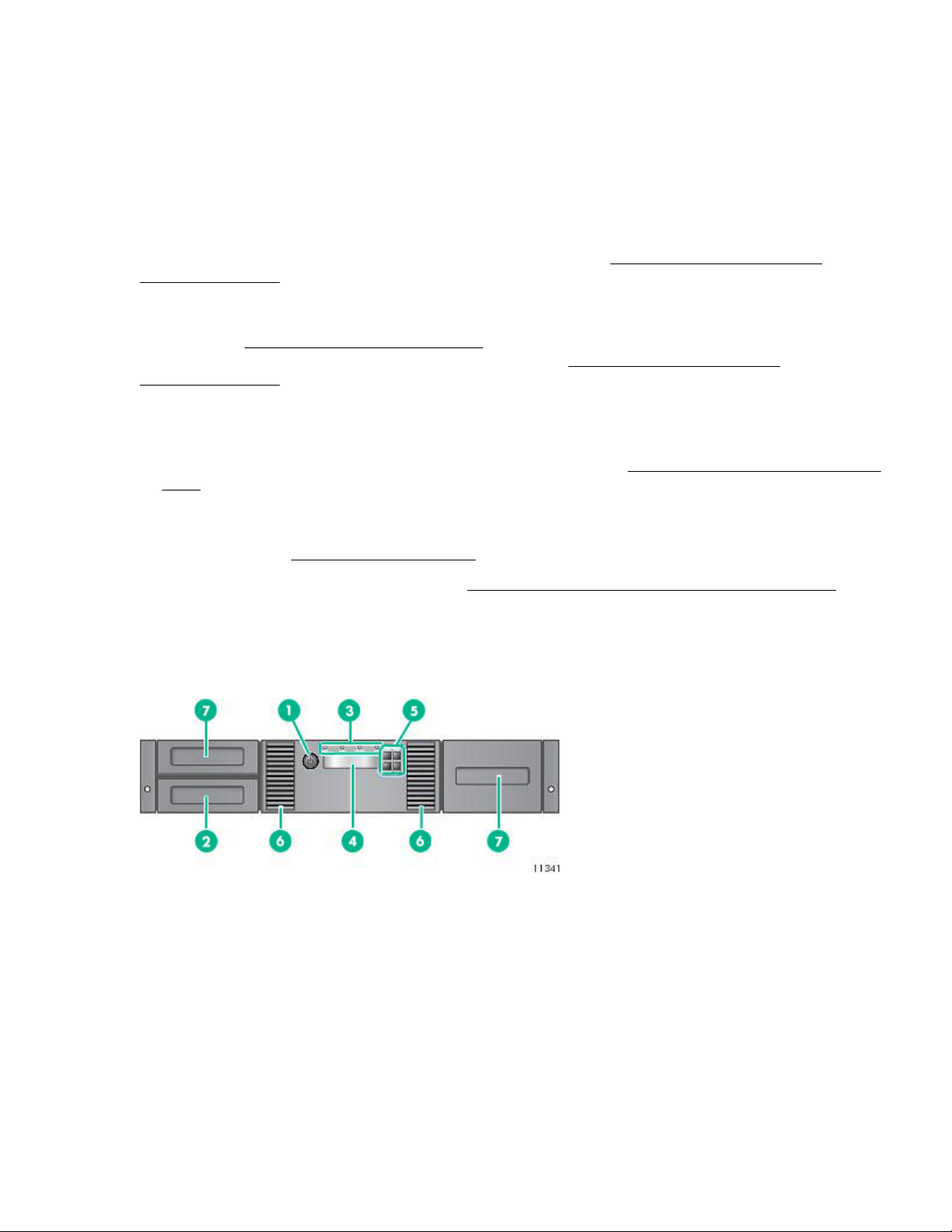
MSL2024 front panel
1. Power button 2. Magazine, mailslot location
3. Front panel LEDs 4. Front panel LCD screen
5. Control buttons 6. Air vents
7. Magazines
The OCP includes four LEDs that indicate system status information.
Features 9
Page 10
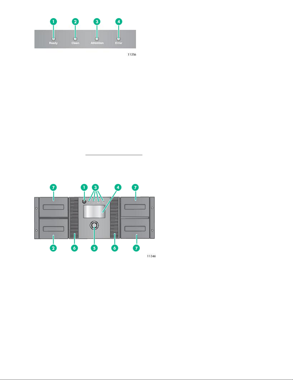
Figure 1: OCP LEDs
1. Green Ready. Illuminated when power is on. Blinking when there is tape drive or robotics
activity.
2. Amber Clean. Illuminated when the tape drive has determined that a cleaning cartridge should
be used. Cleaning is only necessary when the device directs you to do so. Additional
cleaning is not necessary.
3. Amber Attention. Illuminated if the device has detected a condition that requires attention by the
operator.
4. Amber Error. Illuminated if an unrecoverable error occurs. A corresponding error message
displays on the LCD screen.
For OCP functions, see Using the MSL2024 OCP on page 94.
MSL4048 front panel
The front panel provides access to the power button, OCP, left and right magazines, LEDs, and the mailslot.
1. Power button 2. Magazine, mailslot location
3. Front panel LEDs 4. Front panel LCD screen
5. Control buttons 6. Air vents
7. Magazines
The OCP includes four LEDs that indicate system status information.
10 MSL4048 front panel
Page 11

Figure 2: OCP LEDs
1. Green Ready. Illuminated when power is on. Blinking when there is tape drive or robotics
activity.
2. Amber Clean. Illuminated when the tape drive has determined that a cleaning cartridge should
be used. Cleaning is only necessary when the device directs you to do so. Additional
cleaning is not necessary.
3. Amber Attention. Illuminated if the device has detected a condition that requires attention by the
operator.
4. Amber Error. Illuminated if an unrecoverable error occurs. A corresponding error message
displays on the LCD screen.
For OCP functions, see Using the MSL4048, MSL8048, and MSL8096 OCP on page 122.
MSL8048 and MSL8096 front panel
1. Power button 2. Magazine, mailslot location
3. Front panel LEDs 4. Front panel LCD screen
MSL8048 and MSL8096 front panel 11
Table Continued
Page 12
5. Control buttons 6. Air vents
7. Magazine 8. Observation window
9. 12-slot mailslot (MSL8096 only) 10. Magazine (MSL8096 only)
The OCP includes four LEDs that indicate system status information.
Figure 3: OCP LEDs
1. Green Ready. Illuminated when power is on. Blinking when there is tape drive or robotics
activity.
2. Amber Clean. Illuminated when the tape drive has determined that a cleaning cartridge should
be used. Cleaning is only necessary when the device directs you to do so. Additional
cleaning is not necessary.
3. Amber Attention. Illuminated if the device has detected a condition that requires attention by the
operator.
4. Amber Error. Illuminated if an unrecoverable error occurs. A corresponding error message
displays on the LCD screen. For more information, see The library displays errors on
page 145.
For OCP functions, see Using the MSL4048, MSL8048, and MSL8096 OCP on page 122 .
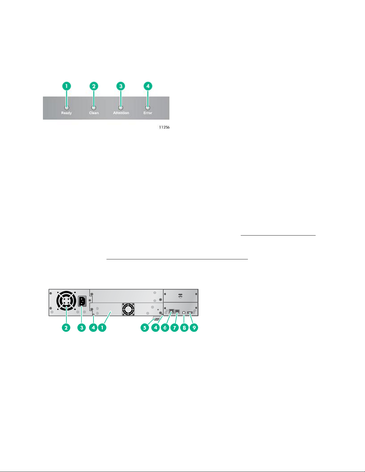
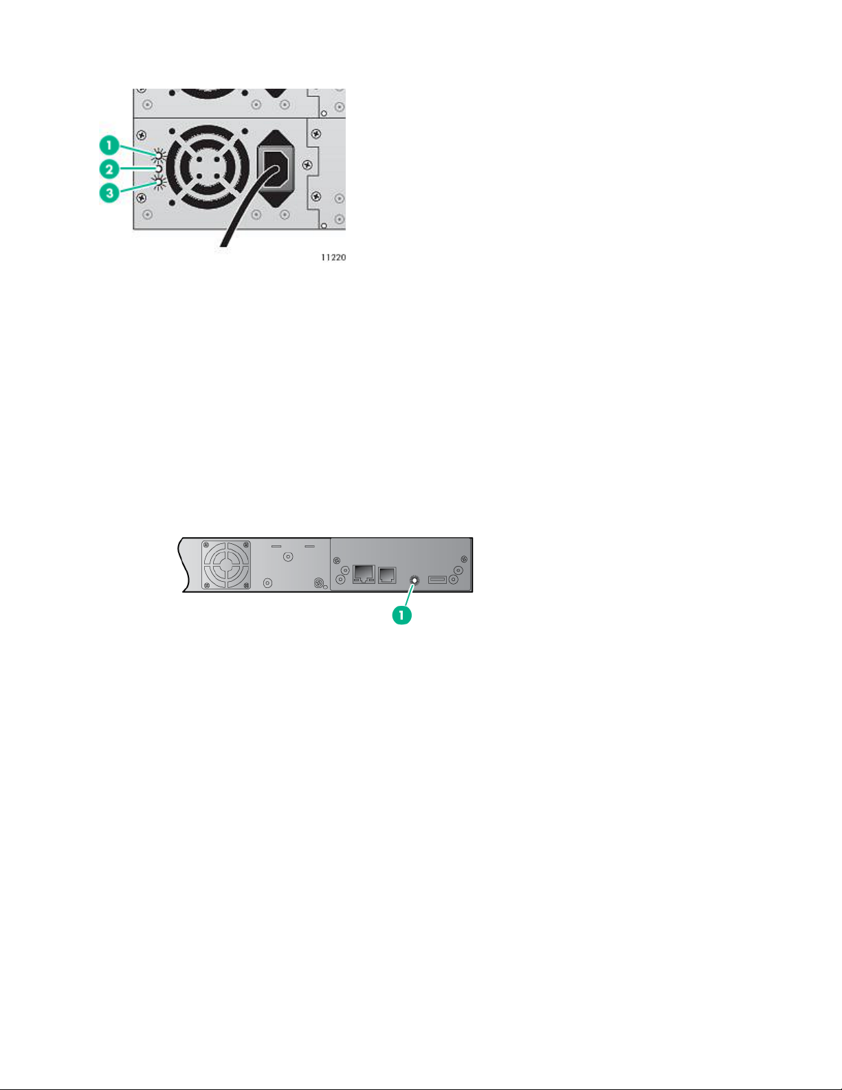
MSL2024 back panel
1. Tape drive assembly 2. Fan
3. Power connector 4. Magazine release hole
5. Pull-out tab containing the serial number and other
product information
6. Ethernet port
7. Serial port (Factory use only) 8. Controller health status indicator
9. USB port
12 MSL2024 back panel
Page 13
MSL4048 back panel
1. Tape drive assembly 2. Fan 3. Power connector
4. Magazine release hole 5. Pull-out tab containing the serial number
and other product information
7. Serial port (Factory use
only)
8. Controller health status indicator 9. USB port
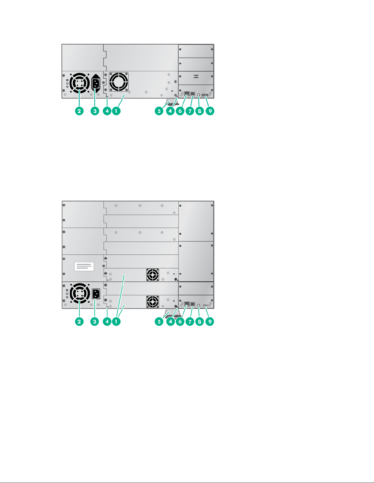
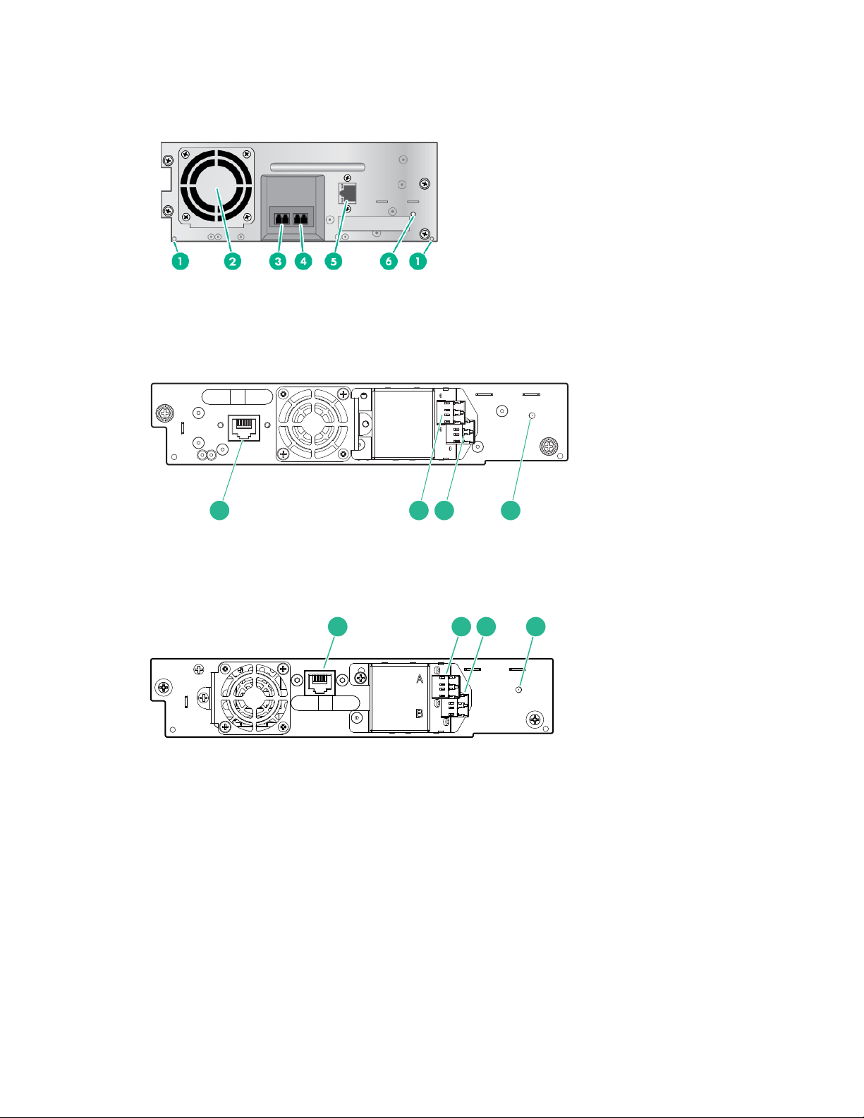
MSL8048 and MSL8096 back panel
6. Ethernet port
Figure 4: MSL8084 or MSL8096 back panel overview
1. Tape drive assembly 2. Fan
3. Power connector 4. Magazine release hole
5. Pull-out tab containing the serial number and other
product information
7. Serial port (Factory use only) 8. Controller health status indicator
9. USB port
6. Ethernet port
MSL4048 back panel 13
Page 14
Power supply back panel (MSL4048, MSL8048 and MSL8096)
Figure 5: Power supply LEDs
1. Blue AC power is connected.
2. Yellow Fan failure. The fan is running too slow or is defective.
3. Green The power supply is producing good power for the library.
Controller health status indicator
The controller health status indicator is a green LED that pulses on and off in approximately one second
cycles during normal operation. The LED is on the back panel in the lower right corner.
Figure 6: Controller health status indicator location
1. Controller health status LED
14 Power supply back panel (MSL4048, MSL8048 and MSL8096)
Page 15
Tape drive back panels
1 2 3 4
1 2 3 4
LTO-4 and LTO-5 full-height FC tape drive back panels
LTO-5 half-height and LTO-6 FC tape drive back panels
1. Magazine release hole
2. Fan
3. FC port A
4. FC port B (when present)
5. Tape drive Ethernet port (when present)
6. Tape drive power indicator
1. Tape drive Ethernet port
2. FC port A
3. FC port B (LTO-6)
4. Tape drive power LED,
green
LTO-7 and LTO-8 FC tape drive back panels
1. Tape drive Ethernet port
2. FC port A
3. FC port B
4. Tape drive power LED,
green
Tape drive back panels 15
Page 16
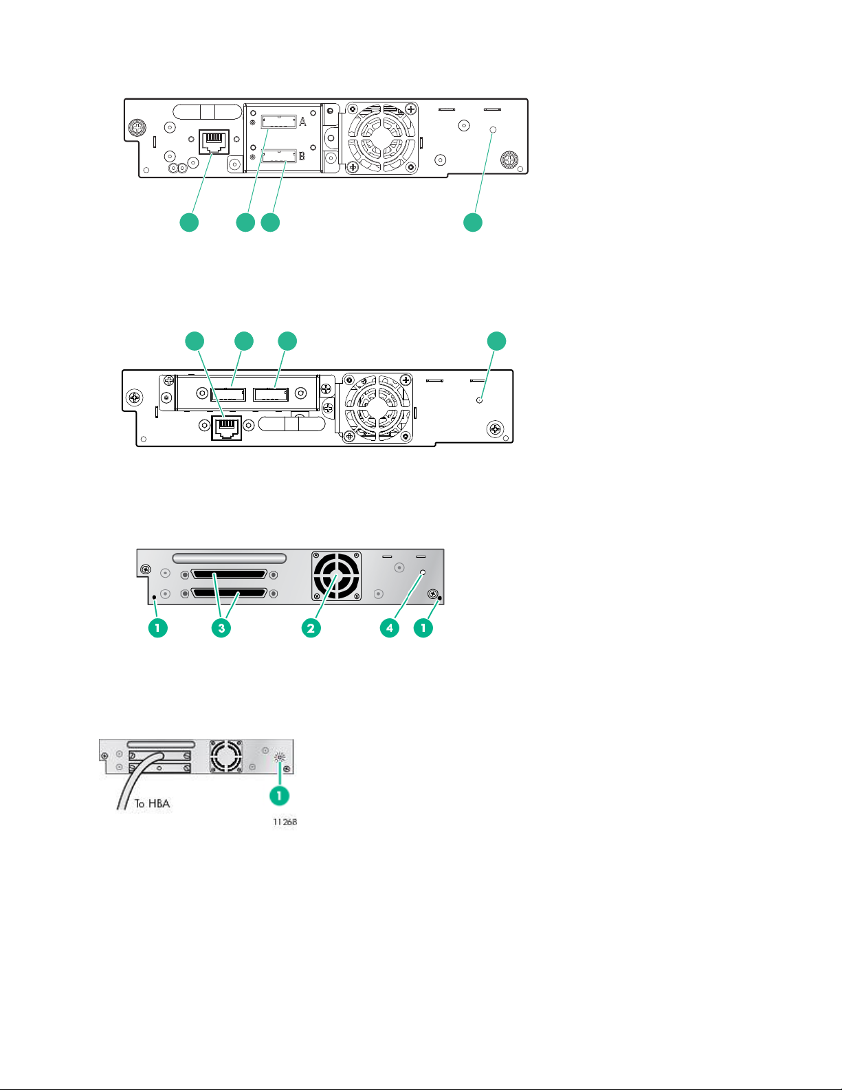
LTO-4, LTO-5, and LTO-6 SAS tape drive back panels
1 2 3 4
1 2 3 4
LTO-7 and LTO-8 SAS tape drive back panels
1. Tape drive Ethernet port
2. SAS port A
3. SAS port B (LTO-6)
4. Tape drive power LED,
green
1. Tape drive Ethernet port
2. SAS port A
3. SAS port B
4. Tape drive power LED,
green
Parallel SCSI tape drive back panel
Tape drive power indicator
Each tape drive has a green power indicator LED, which indicates that the tape drive is powered on.
Figure 7: Tape drive power indicator
1. Tape drive power indicator
1. Magazine release hole
2. Fan
3. Parallel SCSI ports
4. Tape drive power indicator
Library options
16 Tape drive power indicator
Page 17

Redundant power supply
The MSL4048, MSL8048, and MSL8096 tape libraries have a redundant power supply option. The redundant
power supply allows the library to continue operating when one power supply fails. With the redundant power
supply system, the library can monitor the status of each power supply and power supply fan. The redundant
power supply can be installed without powering off the library.
For instructions on installing the redundant power supply, see Installing a redundant power supply.
HPE StoreEver 1/8 G2 Tape Autoloader and MSL Tape Libraries Encryption Kit
The encryption kit provides secure generation and storage of encryption keys. The encryption kit can be used
with any StoreEver 1/8 G2 Tape Autoloader or MSL2024, MSL3040, MSL4048, MSL6480, MSL8048, and
MSL8096 Tape Library with at least one LTO-4 or later generation tape drive. The encryption kit cannot be
used with the MSL6000.
The encryption kit supports your manual security policies and procedures by providing secure storage for
encryption keys. Access to the key server tokens and their backup files is protected with user-specified
passwords. You will need to create processes to protect the tokens and secure the passwords.
Before enabling the encryption kit, verify that the library is running the most current firmware to ensure
compatibility between the token and library.
To use the encryption kit, insert a key server token in the USB port on the back of the library and then enable
the encryption kit and configure the token from the RMI.
IMPORTANT:
When encryption is enabled with the encryption kit, the library will not use encryption keys from other
sources, such as a key management system or application software. Disable encryption in applications
writing to the library when encryption is enabled with the encryption kit. Applications that attempt to
control encryption while encryption is enabled with the encryption kit will not be able to do so, which can
cause backups or other write operations to fail.
For information about configuring and using the encryption kit, see the encryption kit user guide, which is
available from the Hewlett Packard Enterprise Information Library at http://www.hpe.com/info/storage/
docs.
Command View TL TapeAssure
HPE Command View TL software provides a browser-based GUI for remote management and monitoring of
most Hewlett Packard Enterprise libraries. With Command View TL, you can view and analyze the
performance and health of supported tape drives and media in multiple devices at the same time. In addition,
TapeAssure displays more extensive drive and media health information than is visible in the RMI.
Command View TL software is installed on a management station. The management station can also be used
to manage HPE EML and ESL Tape Libraries. For best performance, locate the management station in the
same physical location and on the same IP subnet as the library. Command View TL software is available for
download without charge from the Hewlett Packard Enterprise website at http://www.hpe.com/storage/
cvtldownload.
For information on installing and using Command View TL, see the HPE Interface Manager and Command
View TL User Guide, available from the information library: http://www.hpe.com/info/storage/docs
Command View TL support is included in all library firmware that supports LTO-5 and later generation tape
drives. To find and download the most up-to-date firmware revision, visit the Hewlett Packard Enterprise
support website at http://www.hpe.com/support/hpesc.
Redundant power supply 17
Page 18
LTFS Support
The HPE StoreOpen Automation application simplifies use of the Linear Tape File System (LTFS)
functionality. LTFS makes tape self-describing, file-based, and easy-to-use. The automation application
extends LTFS functionality, presenting an autoloader or library and its tape cartridges as a collection of
folders. This extension results in easy data access and management. For more information about LTFS
capabilities, see http://www.hpe.com/storage/StoreOpen.
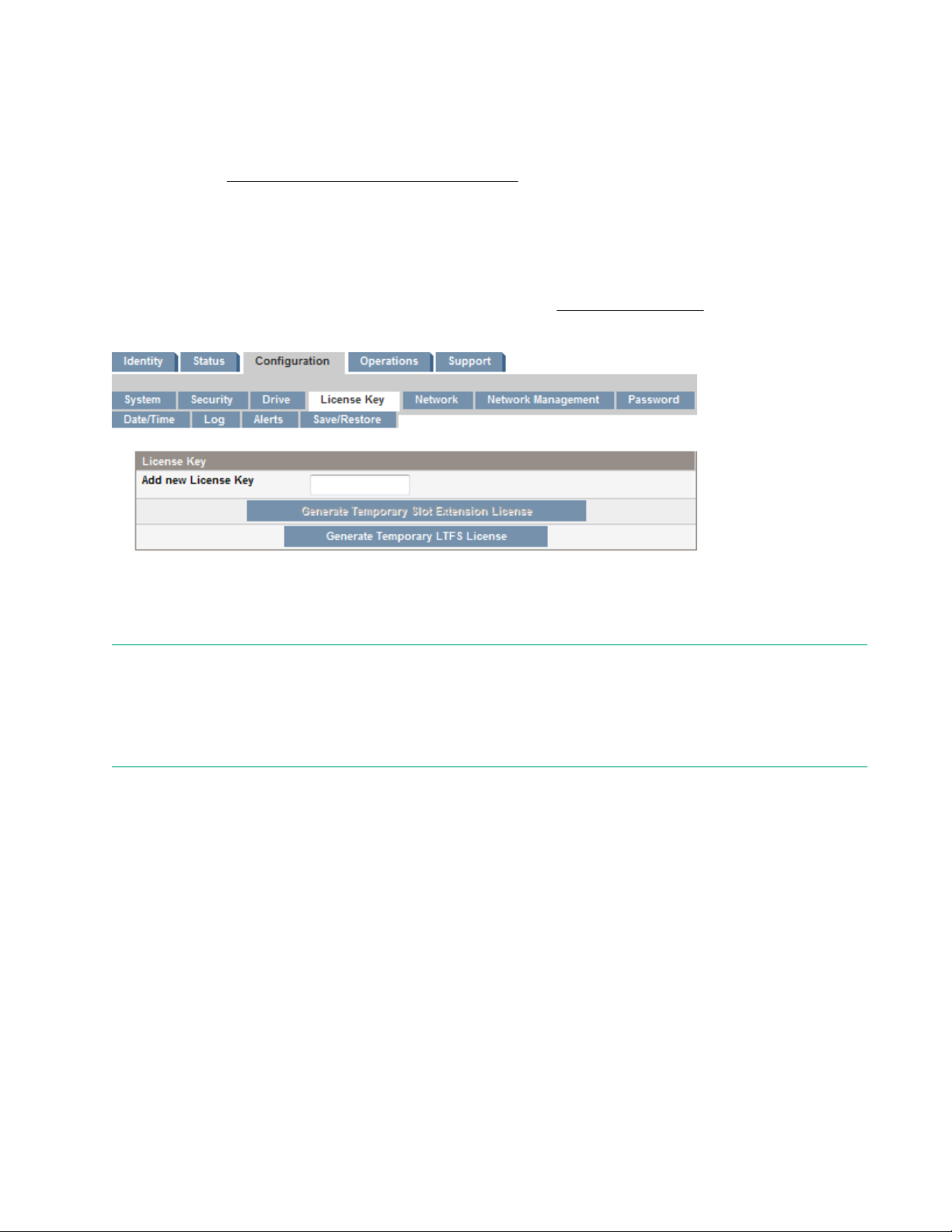
MSL8048 upgrade license
The MSL8048 can be upgraded to the capacity of an MSL8096 with TA739A, the HPE MSL8048 48 to 96 slot
license. The license enables 48 additional storage slots, including 12 slots that can be configured as
additional mailslots. To purchase the upgrade license, contact your Hewlett Packard Enterprise sales
representative or visit the Hewlett Packard Enterprise website at http://www.hpe.com.
Use the RMI Configure > License Key screen to manage the license key.
Figure 8: RMI Configure > License Key screen
After you order the upgrade license, you can access the additional slots immediately by generating a
temporary license key. The temporary key can only be enabled once and is valid for 30 days.
NOTE:
The temporary key is intended to provide instant access to the upgrade capabilities until you receive the
permanent key. The temporary key expires after 30 days. If you do not have a permanent license key before
the temporary key expires, you will lose access to the additional storage slots when the temporary license key
expires.
When you receive the permanent license key from Hewlett Packard Enterprise, enter the key and press
Submit. The permanent license takes effect when the library is rebooted. You might need to reboot the library
to enable the additional slots.
HPE MSL Library Extender
The library extender combines two libraries to create a single extended library. Before installing the extender,
the libraries must be installed in the rack rails supplied with the libraries in adjacent rack locations, one library
above the other.
18 LTFS Support
Page 19
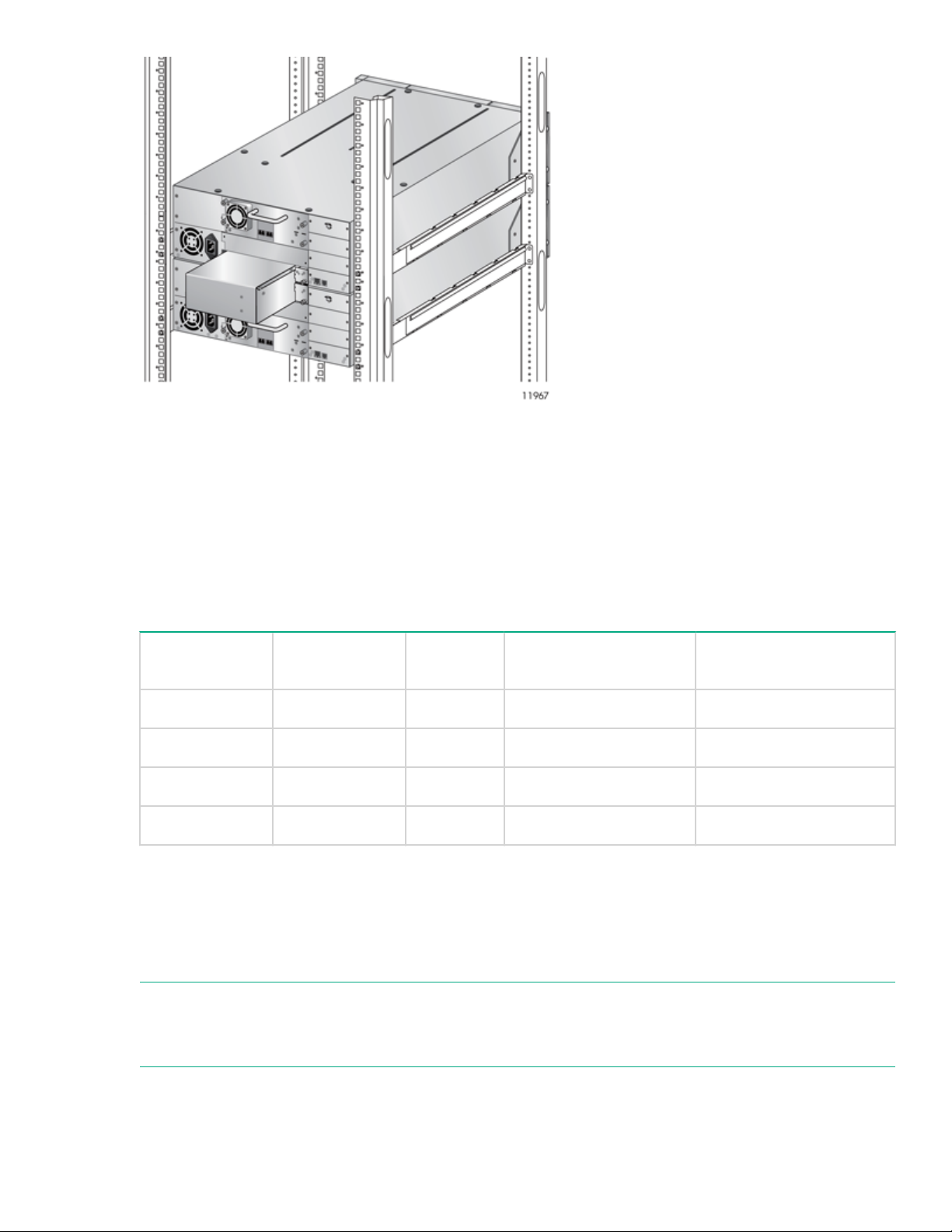
Figure 9: Library Extender installed with two MSL4048 tape libraries
The extender occupies the lower half-height drive bay of the upper library and the top half-height drive bay of
the lower library.
The upper library controls the extended library and is called the master library. The extended library uses only
the master library OCP, USB port, and Ethernet connection.
The master library controls the lower library. The lower library OCP, USB port, and Ethernet connection are
not used by the extended library.
Table 1: Library extender supported configurations
Master library Lower library Total slots Total half-height drive
bays
MSL4048 MSL2024
MSL4048 MSL4048
MSL8096 MSL2024 120 3+1 3+0
MSL8096 MSL4048 144 3+3 3+1
If you are using the encryption kit with both libraries and then install the extender, you will need to combine
the encryption keys onto a single key server token. The extended library only uses the USB port and key
server token in the master library; the USB port in the lower library is inactive. For instructions on combining
the keys onto a single token, see the encryption kit user guide. If the number of keys on the two tokens is
greater than 100, use the Number of Keys to Backup option to generate a backup file with a subset of the
keys from one of the tokens to restore to the other token.
NOTE:
Libraries that require a license to enable all slots must have all slots licensed to operate with the Library
Extender.
72 3+1 1+0
96 3+3 1+1
Total full-height drive
bays
Features 19
Page 20

Hardware-based encryption
The LTO-4 and later generation tape drives include hardware capable of encrypting data while writing data,
and decrypting data when reading. Hardware encryption can be used with or without compression while
maintaining the full speed and capacity of the tape drive and media.
Encryption is the process of changing data into a form that cannot be read until it is deciphered with the key
used to encrypt the data. Encryption protects the data from unauthorized access and use. LTO tape drives
use the 256-bit version of the industry-standard AES encrypting algorithm to protect your data.
To use this feature, you need:
• The 1/8 G2 & MSL Encryption Kit or a KMIP-based key server or a backup application that supports
hardware encryption.
• LTO-4 or later generation media; no encryption will be performed when writing LTO-3 and earlier
generations of tape.
Your company policy will determine when to use encryption. For example, your company could require
encryption of company confidential and financial data, but not for personal data. Company policy will also
define how to generate and manage encryption keys. Backup applications that support encryption will
generate a key for you or allow you to enter a key manually.
For information about using the encryption kit, see HPE StoreEver 1/8 G2 Tape Autoloader and MSL Tape
Libraries Encryption Kit on page 17.
KMIP-based key servers
The library supports integration with encryption key management servers using the Key Management
Interoperability Protocol (KMIP) standard. KMIP is an industry standard protocol for communications between
a key management server and an encryption system. The KMIP technical committee of the OASIS standards
body (Organization for the Advancement of Structured Information Standards) developed the KMIP
specification.
The KMIP feature allows the library to obtain encryption keys from selected KMIP-compliant key managers.
These keys can be used to encrypt data as it is written to tape. Up to six key servers can be configured for
failover purposes.
For instructions on configuring the KMIP feature, see the HPE StoreEver MSL Tape Libraries Encryption Key
Server Configuration Guide, available from the Enterprise Information Library at http://www.hpe.com/info/
storage/docs.
Key managers
To use the KMIP feature, the library must have access to a KMIP key manager. Hewlett Packard Enterprise
only supports KMIP when used with a supported key manager, listed in the compatibility matrix at http://
www.hpe.com/storage/DAPRcompatibility.
Operation
When the KMIP feature is enabled and properly configured, tape data will automatically be encrypted with
keys delivered from the KMIP key manager. Tapes are encrypted on a key-per-tape basis.
Write, and append operations: The tape drive will request a key when data is written. The library, acting as
an intermediary, can request the key manager to create a key. The library then obtains that key and delivers it
to the tape drive. A name, which is associated with the media identifier, identifies the key. The key is not
retained in the tape drive any longer than necessary to perform encryption operations.
Read operations: The tape drive will request a key. The library, acting as an intermediary, obtains the key
identifier, requests that key from the key manager, and delivers it to the tape drive. The key is not retained in
the tape drive any longer than necessary to perform decryption operations.
20 Hardware-based encryption
Page 21

Licensing
The KMIP feature requires that the StoreEver MSL2024/4048/8096 KMIP license has been installed before
the feature can be enabled and configured.
Application-managed encryption
Hardware encryption is off by default and is switched on by settings in your backup application. The backup
application also generates and supplies the encryption key. Your backup application must support hardware
encryption for this feature to work. For a current list of suitable backup software, see the compatibility matrix
at: http://www.hpe.com/storage/DAPRcompatibility
NOTE:
The library can only obtain encryption keys from one source. Using the encryption kit will prevent applicationmanaged encryption.
Encryption is primarily designed to protect the media once it is offline and to prevent it being accessed from
another machine. The tape drive can read and append the encrypted media without being prompted for a key
while the machine and application that first encrypted the tape are accessing the tape.
There are two main instances when you will need to know the key:
• If you try to import the media to another machine or another instance of the backup application.
• If you are recovering your system after a disaster.
NOTE:
Encryption with keys that are generated directly from passwords or passphrases might be less secure than
encryption using truly random keys. Your application will explain the available options and methods. Refer to
the application user documentation for more information.
If you are unable to supply the key when requested to do so, no one will be able to access the encrypted
data, including support engineers.
This feature guarantees the security of your data, but also means that you must carefully manage the
encryption key used to generate the tape.
CAUTION:
Keep a record or backup of your encryption keys and store it in a secure place separate from the
computer running the backup software.
For detailed instructions about enabling encryption, see the documentation supplied with your backup
application or with the encryption kit. The documentation will also highlight any default states, for example
when copying tapes, that might need to be changed when using encrypted tapes.
Logical libraries
You can configure a tape library with multiple tape drives into logical libraries. Each logical library must
contain at least one tape drive. Each logical library is configured independently, allowing use by different
backup applications and with different backup policies. For example, one logical library could perform a
backup operation for one department while the second logical library restores data for another department.
Data cartridges in one logical library cannot be shared with other logical libraries.
If the mailslot is enabled, all logical libraries have access to the mailslot. The tape library prohibits a cartridge
that was placed in the mailslot by one logical library from being moved into another logical library. The library
allows a cartridge that was placed in the mailslot by the operator to be moved into any logical library. If
Application-managed encryption 21
Page 22
sharing the mailslot among logical libraries is an issue in your environment or your backup application does
not support mailslot sharing, disable the mailslot.
Each logical library has a unique serial number and World Wide Identifier (WWID), which can be found in the
RMI Identity > Library screen.
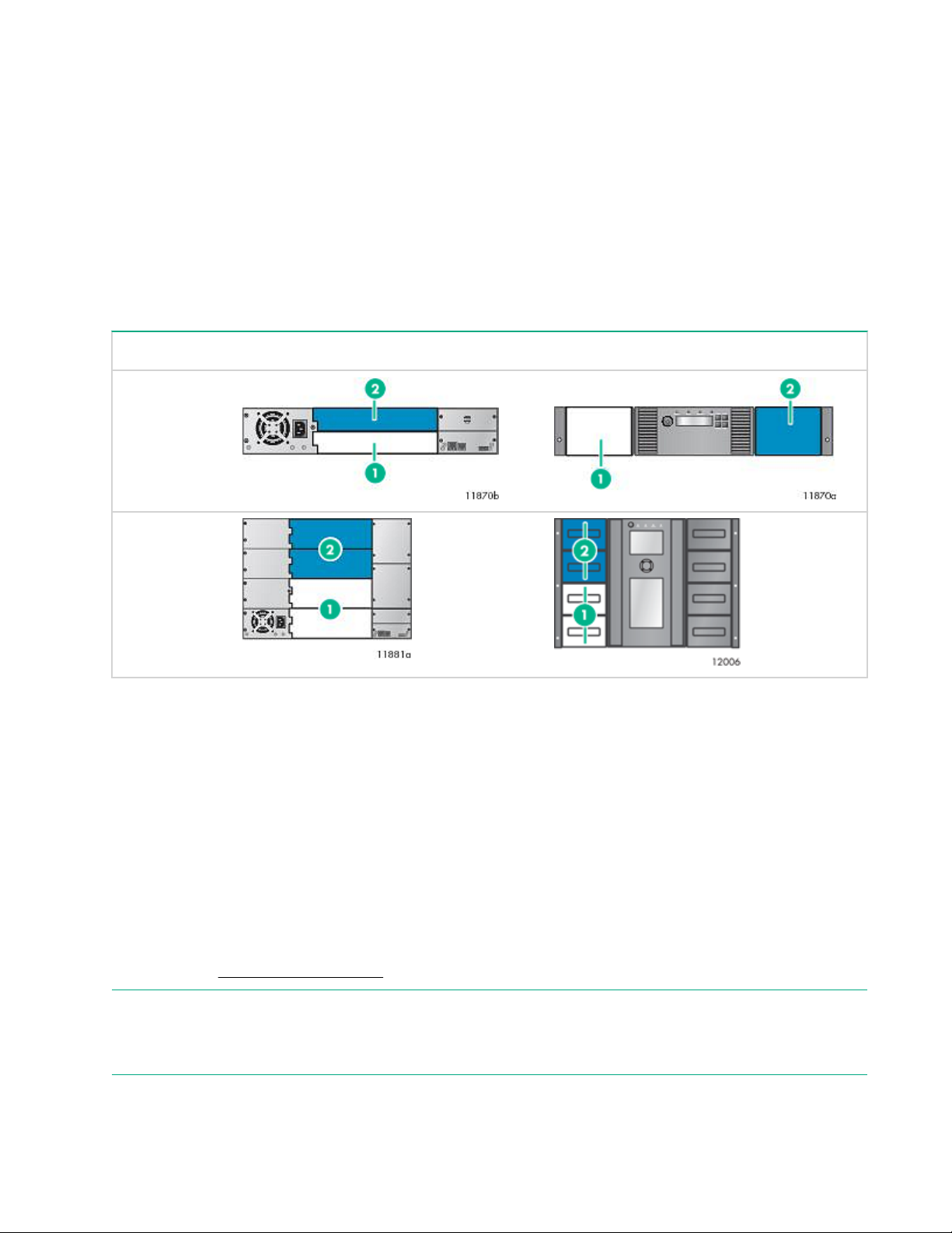
MSL2024 and MSL8048 Tape Libraries partitions
An MSL2024 tape library with two tape drives can be configured into two logical libraries. Each logical library
is assigned one tape drive and one magazine.
An MSL8048 with at least two tape drives can be configured into two logical libraries. Each logical library is
assigned at least one tape drive and two magazines.
Table 2: MSL2024 and MSL8048 Tape Libraries partitioned into two logical libraries
Tape drives Magazines
MSL2024
MSL8048
1. Logical library 1 tape drives and magazines
2. Logical library 2 tape drives and magazines
MSL4048 and MSL8096 Tape Libraries partitions
The MSL4048 and MSL8096 Tape Libraries can be configured into two to four logical libraries, depending on
the number of tape drives installed. The MSL4048 supports up to two full-height tape drives or up to four halfheight tape drives. The MSL8096 supports up to four half-height or full-height tape drives.
Each logical library includes the tape drives in specific drive locations. If there is not a tape drive in the top
half of the library, you might need to move a tape drive. If the library only has two tape drives installed in the
bottom two drive bays, move one tape drive to the top half of the library. Power off the tape drive from the RMI
Configuration > Drive screen before moving the tape drive. For instructions on removing and replacing a
tape drive, see Replacing a tape drive on page 216.
NOTE:
The MSL4048 tape library will not operate with a full-height tape drive installed in the middle two half-height
drive bays. Only install a full-height tape drive in either the upper or lower two half-height drive bays.
22 MSL2024 and MSL8048 Tape Libraries partitions
Page 23
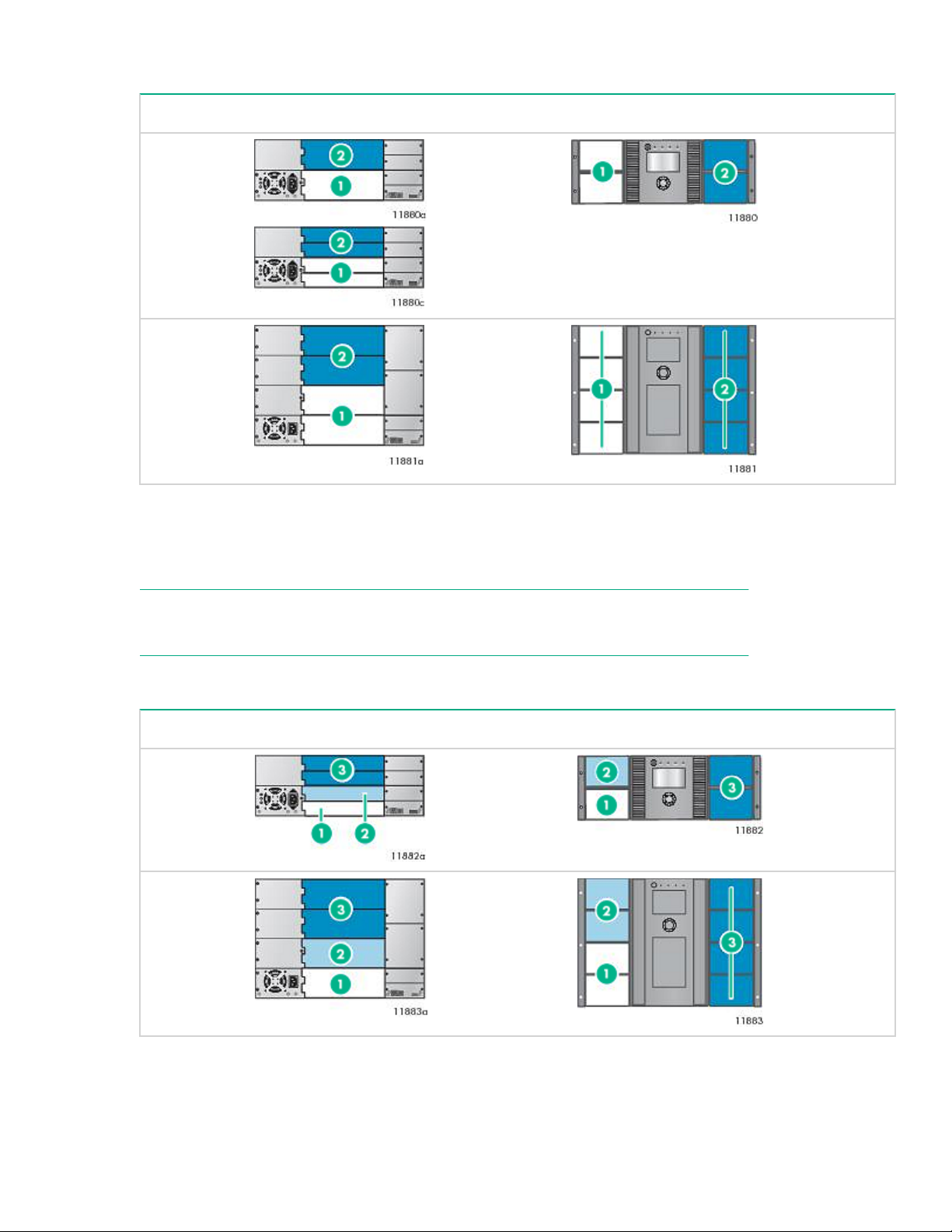
Table 3: MSL4048 and MSL8096 Tape Libraries partitioned into two logical libraries
Tape drives Magazines
MSL4048
MSL8096
1. Logical library 1 tape drives and magazines.
2. Logical library 2 tape drives and magazines.
NOTE:
In the MSL8096, half-height tape drives are installed in the bottom half of each drive bay.
Table 4: MSL4048 and MSL8096 tape libraries partitioned into three logical libraries
Tape drives Magazines
MSL4048
MSL8096
Features 23
Page 24
1. Logical library 1 tape drive and magazines 2. Logical library 2 tape drive and magazines
3. Logical library 3 tape drives and magazines.
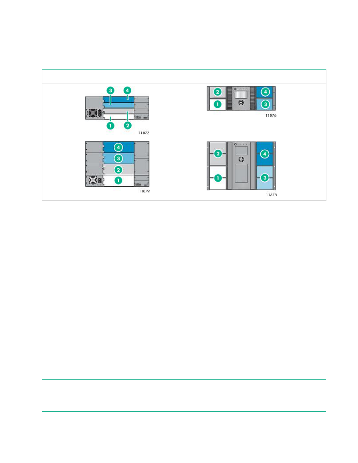
Table 5: MSL4048 and MSL8096 Tape Libraries partitioned into four logical libraries
Tape drives Magazines
MSL4048
MSL8096
1. Logical library 1 tape drive and magazines 2. Logical library 2 tape drive and magazines
3. Logical library 3 tape drive and magazines 4. Logical library 4 tape drive and magazines
Control path and data path failover
With high dependency on access to business information, safe-guarded data and limited backup windows, the
reliability of the backup hardware and software is vital. Additionally, backup operations are automated, often
run at night, and any first pass operator intervention is done remotely. To assist with these enterprise
demands, Hewlett Packard Enterprise supports data path and control path failover for MSL2024, MSL4048,
MSL8048, and MSL8096 tape libraries with LTO-5 and LTO-6 FC tape drives. Failover functionality in the
LTO-5 and LTO-6 tape drives and in the tape libraries transfers the active path and all settings to the standby
path following failures.
• Data path failover—a standby path is configured for the data path to the tape drive and activated
following link failures.
• Library control path failover—a second drive is configured to host a standby library control path that can
be activated following link failures.
For additional information about path failover technology and configuration, see the HPE StoreEver Tape
Libraries LTO-5 and LTO-6 Failover User Guide, which is available from the HPE Enterprise Information
Library at http://www.hpe.com/info/storage/docs.
NOTE:
Path failover is not currently supported for LTO-7 and later generation tape drives in the MSL2024, MSL4048,
MSL8048, or MSL8096 tape libraries.
24 Control path and data path failover
Page 25

Installing the tape library
Procedure
1. Plan the installation.
•
Location requirements
• FC configuration information
• SAS configuration information
• Parallel SCSI configuration information
2. Prepare the host
3. Unpack the shipping container
4. Remove the shipping lock
5. Install the library in a rack
6. Install the tabletop conversion kit
7. Install tape drives
8. Change the SCSI address (parallel SCSI drives only)
9. Connect the parallel SCSI cable
10. Connect the FC cable
11. Connect the SAS cable
12. Power on the library
13. Configure the library
14. Verify the connection
15. Label the tape cartridges
16. Verify the installation
17. Configure additional features
Location requirements
Select an open rack location with access to the host server and a power outlet. If possible, install the library in
the middle or higher part of the rack to avoid dust from the floor and to allow easy access to the mailslot and
magazines.
IMPORTANT:
The library must be mounted on the enclosed rack rails. Placing the library on a surface, such as a table
top or rack shelf, could result in library errors.
If installing the library with the library extender, determine the master and lower units, and install them in
adjacent rack locations, with the master library directly above the lower library. To install the extender, both
libraries must be installed in the rack rails.
Installing the tape library 25
Page 26

Table 6: Library extender supported configurations
Master Library Lower Library
MSL4048 MSL2024
MSL4048 MSL4048
MSL8096 MSL2024
MSL8096 MSL4048
Table 7: Location criteria
Criteria Definition
Rack requirements HPE G2 Enterprise Series, Enterprise Series, G2 Advanced Series, Advanced
Series, Standard Series and other HPE square-hole or round-hole racks
Rack space
requirements
Room temperature 10-35º C (50-95º F) ) for the tape library. Some tape drives have a more limited
Power source AC power voltage: 100-127 VAC; 200-240 VAC
Weight without media MSL2024: 13.6 kg (29.9 lb) - 15.6 kg (34.3 lb)
Weight with media MSL2024: 18.4 kg (40.5 lb) - 20.4 kg (44.9 lb)
MSL2024: 2U
MSL4048: 4U
MSL8048 and MSL8096: 8U
temperature range when operating at high altitudes. Verify the tape drive operating
requirements before installing a tape drive in a high altitude environment
Line frequency: 50-60 Hz
Place the library near an AC outlet. The AC power cord is the main AC disconnect
device for the library and must be easily accessible at all times.
MSL4048: 18.6 kg (40.9 lb) -24.6 kg (54.1 lb)
MSL8048 and MSL8096: 44.6 kg (98.3 lb) - 46.6 kg (102.7 lb)
MSL4048: 28.2 kg (62.0 lb) - 34.2 kg (75.2 lb)
MSL8048: 54.2 kg (117.4 lb) - 56.2 kg (121.9 lb)
Air quality Place the library in an area with minimal sources of particulate contamination. Avoid
26 Installing the tape library
MSL8096: 66.8 kg (147.2 lb) - 68.8 kg (151.7 lb)
areas near frequently used doors and walkways, stacks of supplies that collect dust,
printers, and smoke-filled rooms.
Excessive dust and debris can damage tapes and tape drives.
Table Continued
Page 27

Criteria Definition
Humidity 20-80 percent relative humidity noncondensing
Clearance Back: Minimum of 15.4 cm (6 inches)
Front: Minimum of 30.8 cm (12 inches)
Sides: Minimum of 5.08 cm (2 inches)
FC connection information
Connect the FC tape drive directly to the server with an HBA or indirectly through a SAN with an FC switch.
Table 8: FC drive interface speeds
LTO generation Supported speeds
LTO-3, LTO-4 1 Gb, 2 Gb, 4 Gb
LTO-5, LTO-6, LTO-7, LTO-8 2 Gb, 4 Gb, 8 Gb
Most supported tape drives have two FC ports. Only one port can be used at a time, but both ports can be
connected for path failover or with software that supports multipath. If you are using only one port, you can
use either port. Path failover is a licensed library feature.
Direct connection
The host must have a 2 Gb, 4 Gb, 8 Gb, or 16 Gb FC HBA. A 4 Gb HBA is recommended for LTO-4 tape
drives. An 8 Gb or faster HBA is recommended for LTO-5 and later generation tape drives. To verify that an
HBA is supported on your server and qualified for the tape drive, see the DAPR compatibility matrix at: http://
www.hpe.com/storage/DAPRcompatibility
A server that has FC-attached hard drives performs best with at least two FC ports. Using the same FC port
for disk and tape drive access can cause performance degradation.
SAN connection
All switches between the host and the tape drive must be of the appropriate type. A 2 Gb switch in the path
might cause performance degradation when backing up highly compressible data.
Configure zoning on the FC switch so that only the backup servers can access the tape drive. For more
information, see the switch documentation.
Cable requirements
An FC cable is required for each FC port you plan to use. The tape drive has an LC-style connector. The
maximum cable length is based on the tape drive and external cable type.
Drive type Cable type 2 Gb 4 Gb 8 Gb
All OM2 0.5 - 300 m 0.5 - 150 m Not supported
LTO-5 HH*
OM3, OM4 0.5 - 300 m 0.5 - 150 m 0.5 - 50 m
Table Continued
FC connection information 27
Page 28
Drive type Cable type 2 Gb 4 Gb 8 Gb
All except LTO-5 HH
* The LTO-5 Ultrium 3000 half-height drive is shown as LTO-5 HH.
OM3, OM4 0.5 - 500 m 0.5 - 380 m 0.5 - 150 m
SAS connection information
The server must have a SAS host bus adapter with an external connector.
Table 9: SAS drive interface speeds
LTO generation Supported speeds
LTO-4 1.5 Gb, 3 Gb
LTO-5, LTO-6, LTO-7, LTO-8 1.5 Gb, 3 Gb, 6 Gb
The library uses two SCSI logical unit numbers (LUNs) and requires an HBA with multiple LUN support. Most
Hewlett Packard Enterprise SAS RAID controllers support tape devices; many other SAS RAID controllers do
not support tape devices. To verify the specifications of your HBA or find a list of compatible HBAs, see the
DAPR compatibility matrix: http://www.hpe.com/storage/DAPRcompatibility
CAUTION:
Do not connect the library to a SAS RAID controller unless the DAPR compatibility matrix shows that the
controller is qualified with the library. The server might not be able to boot when the library is connected
to an unsupported SAS RAID controller.
About SAS
SAS is a computer bus technology for transferring data to and from storage devices, including disk drives and
tape drives. SAS-1, which is used for LTO-4 tape drives, is designed to transfer data at 3 Gb/s. SAS-2, which
is used for LTO-5 and later generation tape drives, is designed to transfer data at 6 Gb/s.
CAUTION:
Reliable data transfer requires high-quality cables and connections.
• Always verify that the SAS cable is rated for the data transfer speed of the HBA and tape drive.
• Do not use adapters or converters between the HBA and the tape drive. SAS signal rates require
clean connections and a minimum number of connections between the HBA and the tape drive.
• SAS cables described as "equalized" might not support 6 Gb/s data rates. Do not use equalized
cables with LTO-5 or later generation tape drives unless these cables are verified for 6 Gb/s data
rates.
• For optimal performance, only use cables of the length specified as qualified for your products. Do
not use a SAS cable longer than 6 meters.
28 SAS connection information
Page 29
Cable requirements
SAS uses serial connections, with a direct connection between the host server and each of the storage
devices. This method eliminates the need to configure SCSI buses and assign SCSI IDs, as is required for
parallel SCSI devices.
Most SAS HBA ports have four SAS channels. A tape drive uses one channel, so each HBA port can support
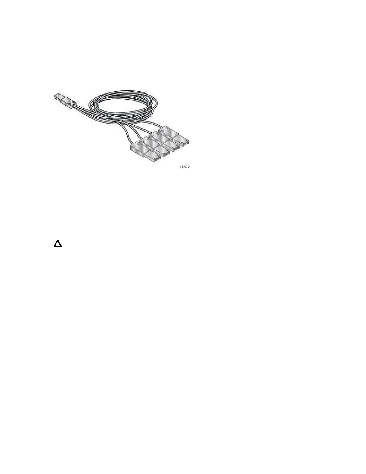
up to four tape drives. You can use a cable with one connector on each end, but only one channel will be
used. The SAS fanout cable recommended for use with the library can connect up to four SAS tape drives to
a single SAS HBA port.
Figure 10: Example SAS fanout cable
Connectors
The host end of the cable must have the same type of connector as the HBA external SAS port.
The tape drive has a mini-SAS connector. The connector is keyed in location 4, which is the standard location
for end devices. If you use a cable other than the one recommended for use with the product, verify that it is
keyed in location 4.
CAUTION:
Mini SAS connectors are keyed. Do not force a SAS cable mini-SAS connector into the tape drive miniSAS port because it might be keyed differently.
World Wide identifiers
A unique identifier called a World Wide Name (WWN) or World Wide Identifier (WWID) identifies a SAS tape
drive. The library assigns the World Wide identifier to the drive bay. When a tape drive is replaced, the World
Wide identifier is reassigned to the new tape drive.
The operating system tracks the World Wide identifier for the drive on each HBA channel. Each of the drive
connectors on a fanout cable is associated with an HBA channel. Once a drive has been connected, keep it
on the same channel to retain the association between the HBA channel and World Wide identifier.
Parallel SCSI configuration information
The parallel SCSI libraries use the Ultra 320 SCSI LVD interface. The libraries use a separate SCSI ID for
each tape drive, with dual LUNs on the master drive SCSI ID to control the tape drive (LUN 0) and library
robotic (LUN 1). Hewlett Packard Enterprise recommends that each Ultrium tape drive has its own bus when
possible.
The parallel SCSI libraries incorporate a wide SCSI-2 or SCSI-3 low-voltage differential (LVD) SCSI bus.
Make sure that your SCSI host adapter or controller supports these standards.
Parallel SCSI configuration information 29
Page 30

IMPORTANT:
The libraries are NOT compatible with a high-voltage differential (HVD) SCSI bus. Do not put the library
on a narrow (50-pin) parallel SCSI bus because doing so will severely degrade performance.
If the host computer will have multiple parallel SCSI devices, you must decide how they will be configured into
one or more parallel SCSI buses.
About parallel SCSI buses
A parallel SCSI bus consists of the host bus adapter (HBA), the parallel SCSI devices, the parallel SCSI
cables, and the terminators. The HBA and devices are connected in a chain, with each device connected to
the next. The last device must have a SCSI terminator. Each device in the chain must have a unique SCSI
address (SCSI ID).
Complex devices, such as the library, assign subaddresses, called logical unit numbers (LUNs), to different
parts of the device. The HBA and operating system must support multiple LUNs, also called LUN scanning,
for the application software to operate the library. HPE Smart Array controllers, most third-party RAID
controllers, and many on-board SCSI controllers do not support multiple LUNs.
An HBA might have one or two channels, with each channel supporting one parallel SCSI bus. Check to see
how many channels the HBA has and what devices are already connected to the HBA. Some devices, such
as parallel SCSI disk drives, could be inside the server.
The devices on a parallel SCSI bus share bandwidth so be careful about which devices you put together on a
bus. Also, putting a single-ended (SE) SCSI device on the bus will slow all the devices on the bus down to SE
speed. To see what kind of parallel SCSI interface a device has, see the interface specifications for the
device.
HBA requirements
For optimum performance, place each tape drive on its own parallel SCSI bus and use a host bus adapter
that can transfer data as fast as the library can read and write. Verify that the operating system supports the
HBA. For best performance, use an Ultra 320 HBA. For current HBA compatibility information, see the
compatibility matrix at: http://www.hpe.com/storage/DAPRcompatability.
IMPORTANT:
Do not connect an LTO tape drive to an SE SCSI bus, as it severely degrades library performance. A
single-ended SCSI host bus adapter severely degrades library performance and limits cable length.
Also, if any SE devices are on the SCSI bus, all the devices on the bus slow down to SE speed,
severely degrading performance.
Multiple LUN support
The library uses a single SCSI ID and two logical unit numbers (LUN). LUN 0 controls the tape drive and LUN
1 controls the robotic. The library requires an HBA that supports multiple LUNs. If multiple LUN support is not
enabled, the host computer cannot scan beyond LUN 0 to discover the library. It just sees the tape drive.
Parallel SCSI HPE Smart Array controllers, RAID controllers, and most on-board HBAs do not support
multiple LUNs. For current HBA compatibility information, see the compatibility matrix at http://
www.hpe.com/storage/DAPRcompatability.
IMPORTANT:
The library requires an HBA that supports multiple LUNs, which is also called “LUN scanning.”
30 Installing the tape library
Page 31

Optimizing throughput
If possible, put each tape drive on its own parallel SCSI bus. For optimum performance, each LTO-4 tape
drive must be on its own Ultra 320 SCSI bus. This configuration will give you the best performance and
easiest installation.
If a tape drive must share a parallel SCSI bus with one or more other devices or the library has multiple tape
drives that must share a bus, follow these guidelines to plan your parallel SCSI buses for the highest
performance:
• Do not put a tape drive on the same parallel SCSI bus as a disk drive because the system and backup
performance will be slow when data is written from the hard drive to tape or from tape to the hard drive.
• Do not put a tape drive on the same parallel SCSI bus as a disk array because the disk and the tape drive
performance will be affected. Most RAID controllers do not support multiple LUNs and the data on the disk
array could become corrupted.
• Avoid putting an SE SCSI device on the same bus as a tape drive because the SE device will slow the
tape drive to SE speed and reduce the allowable cable length.
Default SCSI addresses
NOTE:
The HBA also has a SCSI address, which is typically 7.
Verify that each device on the bus has a unique SCSI address. If these preconfigured addresses will not be
unique on a bus, change the SCSI address of one or more of the tape drives during the installation process.
• MSL2024: For full-height tape drives the default SCSI address is 4. For half-height drives, the default
SCSI address for the bottom drive is 4 and the default SCSI address for the top drive is 5 as shown in the
following illustration.
Figure 11: MSL2024 parallel SCSI tape drive default SCSI addresses
1. Tape drive with SCSI address 4
2. Tape drive with SCSI address 5
• MSL4048: For full-height tape drives the default SCSI address is 4. For half-height drives, the default
SCSI address for the bottom drive in each full-height drive bay is 4 and the default SCSI address for the
top drive is 5.
Installing the tape library 31
Page 32

Figure 12: MSL4048 parallel SCSI tape drive default SCSI addresses
1. Tape drives with SCSI address 4
2. Tape drives with SCSI address 5
• MSL8048 and MSL8096: The default SCSI address for all tape drives is 4.
NOTE:
Use the Library & Tape Tools (L&TT) to check the server parallel SCSI configuration. L&TT is available
without cost from the L&TT website at http://www.hpe.com/support/TapeTools.
Preparing the host
IMPORTANT:
Use proper procedures to prevent electrostatic discharge (ESD). Use wrist-grounding straps and antistatic mats when handling internal components.
Procedure
• If you are not the system administrator of the host computer, check with the system administrator before
powering off the computer.
• For a library with FC drives, install an FC HBA or verify that you have sufficient ports available on a
compatible FC switch.
• For a library with SAS drives, if necessary, install a SAS HBA with an external SAS connector that
supports multiple LUNs. Refer to the host computer and HBA documentation for installation information.
• For a library with parallel SCSI drives, install a parallel SCSI HBA that supports multiple LUNs.
Refer to the host computer and HBA documentation for installation information.
• Install application software and compatible drivers on the host computer. See the application software
manuals for installation and configuration information.
• Install the Library & Tape Tools (L&TT) diagnostic utility to see what devices are connected to the host,
verify the installation, upgrade firmware, and aid in troubleshooting.
Download L&TT without charge from: http://www.hpe.com/support/TapeTools
32 Preparing the host
Page 33

Unpacking the shipping container
CAUTION:
If the temperature in the room where the library will be installed varies 15ºC (30ºF) from the room where
it was stored, allow library to acclimate to the surrounding environment for at least 12 hours before
unpacking the shipping container.
Procedure
1. Clear a level work surface near where you will place the library.
2. Inspect the container for shipping damage. If you notice any damage, report it to the shipping company
immediately.
3. Remove the packaging, accessories, and library from the box one layer at a time.
4. Place the library on a level work surface.
CAUTION:
Do not place the library on either end or its sides as doing so might damage it.
5. Carefully remove the foam padding and then the bag from the library.
6. Save the packaging materials for moving or shipping the library in the future.
7. Verify that you received the following components:
a. Library
b. Ethernet cable
c. Two rack rails with packets of rack hardware
8. Verify that you have the necessary cables.
a. For a library with FC drives, you must provide an FC cable for each FC port you plan to use. See FC
connection information on page 27.
b. For a library with SAS drives, you must provide a SAS cable with the correct connector for your HBA.
See SAS connection information on page 28.
Removing the shipping lock
Skip this step for the MSL8048 and MSL8096.
The shipping lock prevents the robotic transport mechanism from moving during shipment. Remove the
shipping lock before powering on the library. The shipping lock is held in place with a piece of tape and is
located in the top center of the library. After removing the shipping lock, store it on the back panel of the
library for future use.
Procedure
1. Locate the tape and shipping lock at the top of the library.
Unpacking the shipping container 33
Page 34

2. Remove the tape, and then remove the lock.
3. Store the lock on the back panel.
The shipping lock storage location for the MSL4048 is on the back panel, similar to the location on the
MSL2024.
Installing the library in a rack
The MSL8048 and MSL8096 libraries must be installed in a rack with the supplied rails.
WARNING:
The MSL2024 weighs up to 15.6 kg (34.3 lb) without media and up to 20.4 kg (44.9 lb) with media (24
cartridges). The MSL4048 weighs up to 24.6 kg (54.1 lb) without media and up to 34.2 kg (75.2 lb) with
media (48 cartridges).
The MSL8048 weighs up to 46.6 kg (102.7 lb) without media and up to 66.5 kg (151.7 lb) with media (48
cartridges). The MSL8096 weighs up to 46.6 kg (102.7 lb) without media and up to 68.8 kg (151.7 lb)
with media (96 cartridges).
When moving the library, to reduce the risk of personal injury or damage to the library: 1) observe local
health and safety requirements and guidelines for manual material handing, 2) always remove all tapes
to reduce the overall weight of the library, and 3) obtain adequate assistance to lift and stabilize the
library during installation or removal.
34 Installing the library in a rack
Page 35

WARNING:
To reduce the risk of personal injury or damage to equipment:
• Extend the leveling jacks to the floor.
• Ensure that the full weight of the rack rests on the leveling jacks.
• Install the rack stabilizer kit on the rack.
• Extend only one rack component at a time. Racks might become unstable if more than one
component is extended.
Prerequisites
#2 and #3 Phillips screwdrivers
Procedure
1. Select the hardware packet for your rack.
Packet label Applicable racks
7.1 mm Round-Hole Rack HPE supported racks with 7.1 mm round holes in the rack column
9.5 mm Square-Hole Rack HPE supported racks with 9.5 mm square holes in the rack column
2. Install the rails.
a. Using the screws from the packet for your rack and a #3 Phillips screwdriver, secure the front of one rail
to the front of the rack. The support platform of each rail is tapered, narrowing towards the rear.
b. Extend the rail to the depth of the rack and secure the rail to the back of the rack.
c. Install the other rail.
d. For the MSL4048, MSL8048, and MSL8096, insert the clip nuts on the front of the rack in the locations
shown.
The clip nuts will be used to secure the library to the rack.
Installing the tape library 35
Page 36

MSL4048 MSL8048 and MSL8096
1. Clip nut location 2. Rail screw location
3. Bottom of the library 4. U marker
3. Install the library in the rack.
a. Slide the library onto the rails.
b. From the front of the library, secure the front bezel to the rack using a #2 Phillips screw driver placed
through the small holes in the mounting bracket. Tighten the captive screws on each side of the library
until they are seated.
Installing the tabletop conversion kit
The Rack to Tabletop Conversion Kit supports the edges of the library, but is not a structural top.
36 Installing the tabletop conversion kit
Page 37

IMPORTANT:
Do not place any weight on top of the tape library, even with the cover installed.
Procedure
1. Place the cover on a flat, level surface behind the device.
2. Slide the device into the cover until the front panel of the device is aligned with the cover.
Figure 13: Installing the tabletop conversion cover
3. Tighten the captive screws on the front panel until the cover is secure.
Installing tape drives
When possible, install all tape drives during the initial library installation process before the library is powered
on. When installing additional tape drives after the library has been powered on, follow the instructions
included with the tape drive.
TIP:
To assist in aligning the drive, only remove the drive bay covers for one drive at a time.
Procedure
1. Locate an appropriate vacant drive bay on the back of the library.
Install the first tape drive in the bottom drive bay. Install each additional tape drive in the drive bay directly
above the existing tape drives. If you add a tape drive in a space, the new tape drive will be assigned the
next higher drive number, leaving the tape drives numbered out of order. If the settings are restored to the
factory defaults or the library is power-cycled, the drives will be renumbered and you might need to update
the configuration of your backup servers.
NOTE:
The MSL4048 library will not operate with a full-height tape drive installed in the second and third halfheight drive bays. Install a full-height tape drive either in the bottom two drive bays or the top two drive
bays.
NOTE:
If you plan to partition the library into two logical libraries, the second tape drive must be installed in the
third half-height drive bay. For tape drive locations for two logical libraries, see MSL4048 and MSL8096
Tape Libraries partitions.
Installing tape drives 37
Page 38

The MSL8048 and MSL8096 have four tape drive connectors in the locations where full-height tape drives
would be installed. When installing a half-height tape drive, install it in the drive bay directly above a fullheight tape drive or above a half-height drive and half-height face plate pair.
Figure 14: MSL8048 and MSL8096 locations for half-height drives
NOTE: If you plan to partition the library into two logical libraries, the second tape drive must be installed in
the third drive bay. For tape drive locations for two logical libraries, see MSL4048 and MSL8096 Tape
Libraries partitions.
2. Remove the face plate covering the drive bay by removing the screws holding it in place.
Remove one drive bay cover to install a half-height tape drive; remove two drive bay covers to install a fullheight tape drive.
3. Holding the tape drive by the handle and supporting it from the bottom, position the drive on the alignment
rails. Slide the tape drive into the drive bay until it is flush with the back of the library.
4. To secure the tape drive to the chassis, use a torque driver to tighten the thumbscrews on the drive sled to
6 inch pounds or 0.68 N m.
If a torque driver is not available, use a #2 Phillips screwdriver to tighten the thumbscrews until a low initial
threshold torque achieves a snug tight condition.
38 Installing the tape library
Page 39

CAUTION:
All drive bays without tape drives installed must have drive bay covers installed.
Installing a redundant power supply
If you have a redundant power supply for the MSL4048, MSL8048, or MSL8096 tape library, you can install it
now or wait until the installation process is complete.
Procedure
1. Verify that the power to the library is off and the power cord is not attached.
2. On the back of the library, locate the second power supply bay, which is directly above the existing power
supply.
3. Using a #2 Phillips screwdriver, remove the screws that attach the bay cover to the chassis.
4. Position the new power supply on the alignment rails and push it into the library until it is flush with the
back panel.
5. Tighten the blue thumbscrews by hand to secure the power supply to the chassis.
Changing the SCSI address (parallel SCSI drives only)
The preconfigured SCSI address for all full-height tape drives in the MSL2024 and MSL4048, and for all
drives in the MSL8048 and MSL8096 is 4. For half-height drives in the MSL2024 and MSL4048, the bottom
drive of any pair has SCSI address 4 and the top drive has SCSI address 5. If these preconfigured addresses
will not be unique on a bus, you must change the SCSI ID of one or more tape drives before connecting the
library to the computer.
Procedure
1. Plug the power cord into the power connector on the back panel and then plug the cord into the power
outlet.
2. From the front panel, push the round power button to power on the library.
Installing a redundant power supply 39
Page 40

3. From the front panel, set the new SCSI ID for any drives that must have a different SCSI ID from the
Configuration > Change Drive page.
TIP:
The SCSI ID can also be changed from the RMI Configure > Drive screen once the RMI is
configured. See The Configuration > Drive page on page 79.
4. Power off the library by depressing the power button on the front panel.
Connecting the FC cable
NOTE:
Using both ports on a dual-port drive requires path failover or multipath capability in the host application.
Procedure
1. Remove the FC port caps if necessary. Attach one end of the FC cable to Port A on the tape drive.
2. Attach the other end of the FC cable to a switch or HBA.
Connecting the SAS cable
NOTE:
SAS signal rates require clean connections between the HBA and tape drive. Do not use adapters or
converters between the HBA and the tape drive. For reliable operation, use a maximum SAS cable length of 6
meters.
Procedure
1. Determine which end of the cable to plug into the HBA.
a. For a cable with a single connector on each end, the end with the same type of connector as the HBA
is the HBA end.
b. For a SAS fanout cable, the end of the cable with a single connector is the HBA end.
2. Attach the HBA end of the SAS cable to the HBA port.
3. Attach the drive end of the cable to Port A on the tape drive.
If you are using a SAS fanout cable, attach one mini-SAS connector to the port on each tape drive.
40 Connecting the FC cable
Page 41

The unused ends of the SAS fanout cable are single channel and not suitable for use with disk arrays. Use
the other ends to connect additional tape drives, or coil and secure them to the rack to minimize stress on
the connectors.
TIP:
Mini-SAS connectors are keyed. Do not force a mini-SAS connector into the tape drive SAS port
because the connector and port might be keyed differently.
NOTE:
Each tape drive uses one channel. The cable recommended for use with the library maps each of the four
channels from the HBA to one channel on the drive end.
You can plug any of the four drive connectors into any tape drive.
Connecting the parallel SCSI cable
NOTE:
LTO-3 and LTO-4 tape drives are Ultra 320 SCSI LVD devices. Use only cables and terminators specified for
Ultra 320 or labeled as MultiMode. LTO-2 tape drives are Ultra 160 SCSI LVD/SE devices; use only cables
and terminators specified for Ultra 160 or Ultra 320, or labeled as MultiMode.
NOTE:
For optimal performance, do not place any other devices on the same bus as a parallel SCSI tape drive.
Procedure
1. Power off the host server before attaching new devices.
2. Attach one end of the parallel SCSI cable to one of the connectors on the back panel of the tape drive.
3. Attach the other end of the parallel SCSI cable to the connector on the parallel SCSI host bus adapter or to
the connector on the previous device on the parallel SCSI bus.
NOTE:
For best performance, use a Low Voltage Differential Signaling (LVDS) HBA. A Single-Ended (SE) SCSI
host bus adapter works, but severely degrades performance and limits cable length. If any SE devices are
on the same parallel SCSI bus, all of the devices on the parallel SCSI bus slow to SE speed, which
severely degrades performance. Never attach an LTO-3 or LTO-4 tape drive to an SE SCSI bus.
4. Attach the terminator to the remaining parallel SCSI connector on the back panel of the tape drive if the
library is the last or only device on the parallel SCSI bus. Otherwise, attach one end of a parallel SCSI
Connecting the parallel SCSI cable 41
Page 42

cable to the remaining port and the other end to the next device on the parallel SCSI bus. Make sure that
the last device on the parallel SCSI bus is properly terminated.
IMPORTANT:
For the library and tape drives to operate correctly, each SCSI tape drive must have a SCSI
terminator unless the tape drive is part of a properly terminated chain. A tape drive without an
attached SCSI cable must also have a SCSI terminator.
Powering on the library
WARNING:
To reduce the risk of electric shock or damage to the equipment:
• Use an approved power cord. If you have questions about the type of power cord to use, contact
your authorized service provider.
• Use a power cord rated for your product and for the voltage and current marked on the electrical
ratings label of the product. The voltage and current rating of the cord must be greater than the
voltage and current rating marked on the product.
Procedure
1. If you plan to use the RMI, use an Ethernet cable to connect the library to a working LAN connection. The
library Ethernet connector is on the back of the library.
2. Attach a power cable to the power connector on each power supply on the back of the library.
3. Plug the power cables into the nearest properly grounded power outlets.
4. Power on the library by pressing the power button on the front panel.
5. To verify that the library has power, check the LCD screen.
If the library does not have power, check the power connections and your power source.
During the Power On Self-Test (POST), all four LEDs are illuminated briefly, followed by a flashing Ready
LED. When the initialization sequence is complete, the Home screen is displayed.
If the inventory takes over five minutes, the splash screen is displayed. To see the Home screen, press
any button.
6. Plug in the host server and all attached devices.
7. Power on any other devices you powered off earlier.
8. Power on the server.
Configuring the library
Procedure
1. Set the administrator password.
Setting an administrator password provides access to the administrator functions with the RMI or OCP,
and restricts access to administrator functions to only those people who know the administrator password.
42 Powering on the library
Page 43

The library comes with a null administrator password, which until set allows unrestricted access to all
administrative functions through the OCP but not the RMI. Once the administrator password has been set
from the OCP, it can be changed from either the OCP or RMI.
• For the MSL2024, see Changing the administrator password (Configuration > Change Admin
Password) on page 104.
• For the MSL4048, MSL8048, and MSL8096, see Setting and changing the administrator password
(Configuration> Set Admin Password) on page 137.
2. Set the date and time.
The date and time are used by the library to record events. For ease of communication and product
support, set the date and time during the initial installation process.
• For the MSL2024, see Setting the date and time (Configuration > Library Date/Time) on page 109.
• For the MSL4048, MSL8048, and MSL8096, see Setting the library date and time (Configuration >
Set Date and Time) on page 139.
3. If necessary, configure the FC interface.
Recommended FC interface configuration
4. Configure the library network settings.
Configuring the library network settings enables you to monitor, configure, and control most library
functions from the RMI. By default, the device will obtain an IP address from an IPv4 DHCP server.
Optionally, you can configure the device to use a static IP address. Once logged in to the RMI, you can
administer further network changes through the RMI.
• For the MSL2024, see Configuring IPv4 network settings (Configuration > Configure Network
Settings) on page 110.
• For the MSL4048, MSL8048, and MSL8096, see Changing the network configuration
(Configuration > Network) on page 137.
5. The device supports IPv4 and IPv6 Internet Protocols. By default, the device is configured to use IPv4, the
most common version. You can enable IPv6 or both Internet Protocols from the OCP or RMI. Use the RMI
to finish configuring IPv6. (See The Configuration > Network page on page 81.)
Recommended FC interface configuration
Drives connected to a SAN
Leave the FC port at the default settings of Port Speed: Automatic and Port Type: Auto Detect. With these
settings, the tape drive will use the appropriate configuration.
Drives connected directly to the host
• For LTO-7 and later drives, use Loop mode.
• For LTO-6 and earlier drives, leave the FC port at the default settings of Port Speed: Automatic and Port
Type: Auto Detect. With these settings, the tape drive will use the appropriate configuration.
Use the Configuration > Drives screen to change the settings.
Recommended FC interface configuration 43
Page 44

Verifying the connection
Procedure
1. Install the application software and/or drivers that are compatible with the library.
Backup software packages might require additional software or licensing to communicate with the robotics.
For software compatibility information, see the Data Agile BURA Compatibility Matrix at: http://
www.hpe.com/storage/buracompatibility
2. Verify the connection between the library and the host:
a. Install the Library & Tape Tools Diagnostic/Installation Check Utility onto the host computer.
This utility verifies that the unit is connected and communicating with the host server. It also verifies that
the device is functioning and provides diagnostic information. To verify your connections, run the
Library & Tape Tools Installation Check from the programs menu.
L&TT is available without cost at:http://www.hpe.com/support/TapeTools
b. Confirm that the host server operating system recognizes the library.
In Windows, look for tape drives and media changers in the Device Manager.
For more information on verifying the connection of parallel SCSI devices, consult the operating system
documentation.
Labeling the tape cartridges
The library will operate without barcode labels on the cartridges. Using barcode labels in production
environments improves inventory time in the library and eases cartridge handling processes outside the
library.
Attaching a bar code label to each tape cartridge enables the library and application software to identify the
cartridge quickly, which speeds up inventory time. Make using bar code labels on your tapes a practice.
IMPORTANT:
Misusing and misunderstanding bar code technology can result in backup and restore failures. To
ensure that your bar code labels meet Hewlett Packard Enterprise quality standards, always purchase
them from an approved supplier and never print bar code labels yourself.
Prerequisites
High-quality preprinted barcode labels with the correct Media ID.
Procedure
Apply a high-quality preprinted bar code label to each tape cartridge.
LTO tape cartridges have a recessed area on the face of the cartridge next to the write-protect switch. Use
this area for attaching the adhesive-backed bar code label.
44 Verifying the connection
Page 45

IMPORTANT:
Only apply the bar code label as shown, with the alphanumeric portion facing the hub side of the tape
cartridge. Never apply multiple labels onto a cartridge because extra labels can cause the cartridge to
jam in a tape drive
Verifying the installation
Procedure
1. Determine the firmware revision currently installed on the library.
• From the RMI Identity > Library screen.
• From the MSL2024 OCP:
a. From the Home screen, press Next until the display shows Status/Information. Press Enter.
b. Press Next until the display shows Library Information. Press Enter.
c. Press Next until the display shows the Firmware Rev.
The current installed firmware version is displayed.
d. Press Cancel until the display shows the home screen.
• From the MSL4048 OCP Info > Identity Library menu.
2. Determine the current available firmware version from the storage support website:
support/storage
3. If the library does not have the current firmware installed, update to the latest firmware from the RMI
Support > Firmware screen, the OCP Support > Library FW Upgrade menu item, or L&TT.
4. Save the library database
After configuring the library, you can save the configuration database to a USB flash drive from the OCP or
to a file from the RMI Configuration > Save/Restore screen. Having a backup of the library configuration
is helpful when recovering from a configuration error, setting up multiple devices with similar
configurations, or if the library needs service.
Downloading product firmware
Procedure
1. Navigate to the HPE Support website: http://www.hpe.com/support/storage
http://www.hpe.com/
Verifying the installation 45
Page 46

IMPORTANT:
Access to some updates might require product entitlement when accessed through the Hewlett
Packard Enterprise Support Center. You must have an HPE Passport set up with relevant
entitlements.
To view and update your entitlements, and to link your contracts and warranties with your profile,
navigate to: http://www.hpe.com/support/AccessToSupportMaterials
2. Browse or search for the necessary firmware.
3. Download the firmware.
To upgrade firmware from the OCP, copy the firmware image onto a FAT-32 formatted USB flash drive.
Configuring additional features
The tape library has many features to customize it for your organization.
Procedure
1. Naming the tape library, which is done from the RMI Configuration > Network screen. See The
Configuration > Network page on page 81.
2. Partitioning a library with multiple tape drives into logical libraries. See The Configuration > System page
on page 73.
3. Enabling and configuring SNMP network management or Command View TL TapeAssure. See The
Configuration > Network Management page on page 83.
4. Setting up email event notification. See The Configuration > Alerts page on page 87.
5. To use the RMI and OCP in Japanese, enable the Japanese language option through the RMI. See The
Configuration > System page on page 73.
46 Configuring additional features
Page 47

Tape cartridges and magazines
This chapter explains which media to use with the library, and how to label and write-protect tape cartridges.
Careful labeling and handling of the tape cartridges will prolong the life of the tape cartridges and the library.
Tape cartridges
Use the data and cleaning tape cartridges designed for your model of library.
WORM data cartridges
The LTO-3 and later tape drives support both rewritable and WORM data cartridges. Write-Once, Read-Many
(WORM) data cartridges provide an enhanced level of data security against accidental or malicious alteration
of data on the tape cartridge. The WORM data cartridge can be appended to maximize the full capacity of the
tape cartridge. Data cannot be erased or overwritten on the WORM data cartridge. WORM data cartridges
have a two-tone cartridge color for easy identification.
To see whether your backup or archive software application supports WORM cartridges, see the Storage
Media website at http://www.hpe.com/info/storagemedia.
LTO-7 Type M media for LTO-8 drives
The library supports LTO-7 cartridges initialized as Type M media in LTO-8 tape drives. See the library
firmware release notes for specific library firmware revisions that support LTO-7 Type M media.
Important notes for LTO-7 Type M media:
• When a new, unused LTO-7 cartridge has an ‘M8’ bar code label applied, it can be initialized as LTO-7
Type M media.
• Once an LTO-7 cartridge has been initialized to LTO-7 Type M media, the format is irreversible. Do not
place an 'M8' bar code on an LTO-7 cartridge that has been previously used in an LTO-7 drive. A used
LTO-7 cartridge cannot be initialized as LTO-7 Type M media, even in an LTO-8 drive.
• LTO-7 Type M media provides up to 9 TB native capacity, instead of the 6 TB specified for LTO-7. As such,
LTO-7 Type M media can provide up to 22.5 TB with 2.5:1 compression (depending on the data being
compressed.)
• LTO-7 Type M media support regular LTO features, including encryption, LTFS, and compression.
• LTO-7 Type M media are only compatible with LTO-8 tape drives. They are not compatible with LTO-7
drives and will not be compatible with LTO-9 drives.
For more information about LTO-7 Type M media, see http://www.hpe.com/storage/storagemedia.
Recommended practices for using and maintaining tape cartridges
CAUTION:
Do not degauss LTO data cartridges! These data cartridges are prerecorded with a magnetic servo
signal. This signal is required to use the cartridge with the tape drive. Keep magnetically charged
objects away from the cartridge.
• Use only the data cartridges designated for your device.
• Clean the tape drive when the Clean drive LED is illuminated.
Tape cartridges and magazines 47
Page 48

CAUTION:
Use only Ultrium Universal Cleaning Cartridges (UCC).
• Do not drop a cartridge. Excessive shock can damage the internal contents of the cartridge or the
cartridge case itself, making the cartridge unusable.
• Do not expose data cartridges to direct sunlight or sources of heat, including portable heaters and heating
ducts.
• The operating temperature range for data cartridges is 10 to 35º C. The storage temperature range is 16 to
32º C in a dust-free environment with relative humidity always between 20 percent and 80 percent
(noncondensing).
• If the data cartridge has been exposed to temperatures outside the specified ranges, stabilize the cartridge
at room temperature for the same length of time it was exposed to extreme temperatures or 24 hours,
whichever is less.
• Do not place data cartridges near sources of electromagnetic energy or strong magnetic fields such as
computer monitors, electric motors, speakers, or X-ray equipment. Exposure to electromagnetic energy or
magnetic fields can destroy data and the embedded servo code written on the media by the cartridge
manufacturer. The cartridge is unusable without the embedded servo code.
• Place identification labels only in the designated area on the cartridge.
Recommended practices for labeling tape cartridges
The library contains a bar code reader that reads the tape labels and stores the inventory data in memory.
The device then provides the inventory information to the host application, OCP, and RMI. A bar code label on
each tape cartridge enables the bar code reader to identify the cartridge quickly, which speeds up inventory
time. Make using bar code labels on your tape cartridges a practice.
TIP:
The bar code scanner scans each tape or the back of the storage slot until it reads the bar code label for
the cartridge or storage slot, or determines that the slot is empty. The bar code scanner can identify a
properly labeled cartridge on the first scan. It can identify an empty slot on the second scan. It will try
several more scans and then tap on the cartridge before determining that an unlabeled cartridge is in
the slot, which takes about four times as long as identifying a properly labeled cartridge.
The inventory time for an MSL8048 or MSL8096 filled with unlabeled cartridges is about 30 minutes.
Even if you do not need the bar code information, use bar code labels to speed up inventory time.
A proper bar code label includes the Media ID in the last two characters of the bar code. LTO-3 and earlier
generation tape drives prevent later generation media from being loaded into the drive. If an LTO-4 or later
tape drive is installed in the library or is in the removed state, the library will not load an unlabeled cartridge
into an LTO-3 or earlier generation tape drive.
Though not recommended, checking Ignore Barcode Media ID in the RMI Configuration > System screen
will keep the library from interpreting bar code Media IDs.
The host software might track the following information through the associated bar code:
• Date of format or initialization
• Tape cartridge media pool
• Data residing on the tape
48 Recommended practices for labeling tape cartridges
Page 49

• Age of the backup
• Errors encountered while using the tape (to determine if the tape is faulty)
IMPORTANT:
Misusing and misunderstanding bar code technology can result in backup and restore failures. To
ensure that your bar code labels meet Hewlett Packard Enterprise quality standards, always purchase
them from an approved supplier. Do not print bar code labels yourself. To purchase bar code labels, see
the Hewlett Packard Enterprise Storage Media website at:
http://www.hpe.com/storage/storagemedia
For more information, see the Bar Code Label Requirements, Compatibility, and Usage white paper
available from http://www.hpe.com/support/storage.
LTO tape cartridges have a recessed area on the face of the cartridge next to the write-protect switch. Use
this area for attaching the adhesive-backed bar code label. Only apply labels as shown:
Figure 15: Apply the label within the recessed area.
IMPORTANT:
Only apply the bar code label as shown, with the alphanumeric portion facing the hub side of the tape
cartridge. Never apply multiple labels onto a cartridge because extra labels can cause the cartridge to
jam in a tape drive.
Write-protecting data cartridges
All rewritable data cartridges have a write-protect switch to prevent accidental erasure or overwriting of data.
Before loading a cartridge into the device, ensure that the write-protect switch on the front of the cartridge is in
the desired position.
Procedure
• Slide the switch to the right to write-protect the cartridge. An indicator, such as a red mark or small
padlock, is visible showing that the cartridge is write-protected.
Write-protecting data cartridges 49
Page 50

1. Write-enabled 2. Write-protected
3. Write-protect switch 4. Bar code label
5. Insertion arrow
• Slide the switch to the left to allow the library to write data to the cartridge.
Read and write compatibility
Hewlett Packard Enterprise Ultrium data cartridges are fully supported and compatible with all Ultrium tape
products. Because Hewlett Packard Enterprise Ultrium media is Ultrium logo compliant, it can be used with
any other tape drive that bears the Ultrium logo.
LTO-3 drive LTO-4 drive LTO-5 drive LTO-6 drive LTO-7 drive LTO-8 drive
LTO-1 media Read only Incompatible Incompatible Incompatible Incompatible Incompatible
LTO-2 media Read/Write Read only Incompatible Incompatible Incompatible Incompatible
LTO-3 media Read/Write Read/Write
(no
encryption)
LTO-4 media —
unencrypted
LTO-4 media —
encrypted
LTO-5 media —
unencrypted
LTO-5 media —
encrypted
LTO-6 media —
unencrypted
Incompatible Read/Write Read/Write Read only Incompatible Incompatible
Incompatible Read/Write
with
encryption
key
Incompatible Incompatible Read/Write Read/Write Read only Incompatible
Incompatible Incompatible Read/Write
Incompatible Incompatible Incompatible Read/Write Read/Write Incompatible
Read only Incompatible Incompatible Incompatible
Read/Write
with
encryption
key
with
encryption
key
Read only
with
encryption
key
Read/Write
with
encryption
key
Incompatible Incompatible
Read only
with
encryption
key
Incompatible
Table Continued
50 Read and write compatibility
Page 51

LTO-3 drive LTO-4 drive LTO-5 drive LTO-6 drive LTO-7 drive LTO-8 drive
LTO-6 media —
encrypted
LTO-7 media —
unencrypted
LTO-7 media —
encrypted
LTO-7 Type M
media —
unencrypted
LTO-7 Type M
media —
encrypted
LTO-8 media —
unencrypted
LTO-8 media —
encrypted
Incompatible Incompatible Incompatible Read/Write
with
encryption
key
Incompatible Incompatible Incompatible Incompatible Read/Write Read/Write
Incompatible Incompatible Incompatible Incompatible Read/Write
Incompatible Incompatible Incompatible Incompatible Incompatible Read/Write
Incompatible Incompatible Incompatible Incompatible Incompatible Read/Write
Incompatible Incompatible Incompatible Incompatible Incompatible Read/Write
Incompatible Incompatible Incompatible Incompatible Incompatible Read/Write
Read/Write
with
encryption
key
with
encryption
key
Incompatible
Read/Write
with
encryption
key
with
encryption
key
with
encryption
key
CAUTION:
LTO-2 and LTO-3 tape drives require the most recent firmware to identify LTO-4 media immediately.
Without the most recent firmware, loading an LTO-4 cartridge into an earlier generation drive can result
in a long media identification and unload time. The drive might not identify the media and then return a
load error before the application software times out waiting for the load. For proper operation, keep tape
drives updated to the most recent firmware.
Supported media
Use Hewlett Packard Enterprise storage media to prolong the life of the library and tape drives. To learn more
about, or to purchase media, see: http://www.hpe.com/storage/storagemedia
Table 10: Cleaning cartridge for all supported tape drives
Cartridge type Part number
HPE Ultrium universal cleaning cartridge (50 cleans), orange C7978A
Table 11: LTO-4 data cartridges
Cartridge type Part number
HPE LTO-4 Ultrium 1.6TB RW Data Cartridge, green C7974A
HPE LTO-4 Ultrium 1.6TB WORM Data Cartridge, two-tone (green and gray) C7974W
Supported media 51
Page 52

Table 12: LTO-5 data cartridges
Cartridge type Part number
HPE LTO-5 Ultrium 3 TB RW Data Cartridge, blue C7975A
HPE LTO-5 Ultrium 3 TB WORM Data Cartridge, two-tone (blue and gray) C7975W
Table 13: LTO-6 data cartridges
Cartridge type Part number
HPE LTO-6 Ultrium 6.25 TB MP RW Data Tape, purple C7976A
HPE LTO-6 Ultrium 6.25 TB BaFe RW Data Tape, purple C7976B
HPE LTO-6 Ultrium 6.25 TB MP WORM Data Tape, two-tone (purple and gray) C7976W
HPE LTO-6 Ultrium 6.25 TB BaFe WORM Data Tape, two-tone (purple and gray) C7976BW
Table 14: LTO-7 data cartridges
Cartridge type Part number
HPE LTO-7 Ultrium 15 TB RW Data Tape, blue C7977A
HPE LTO-7 Ultrium 15 TB WORM Data Tape, two-tone (blue and gray) C7977W
Table 15: LTO-7 Type M media for LTO-8 drives
Cartridge type Part number
HPE LTO-7 Ultrium Type M 22.5 TB RW Custom Labeled Data Cartridges (20
pack)
HPE LTO-7 Ultrium Type M 22.5 TB RW Non-Custom Labeled Data Cartridges (20
pack)
Table 16: LTO-8 data cartridges
Cartridge type Part number
HPE LTO-8 Ultrium 30 TB RW Data Tape, green Q2078A
HPE LTO-8 Ultrium 30 TB WORM Data Tape, two-tone (green and gray) Q2078W
Magazines
The library has removable magazines. Magazine access is password protected. For safety reasons, the
robotic motion is stopped when a magazine is removed.
The magazines can be released using the OCP, the RMI, or by a manual release. When possible, release the
magazine using the OCP or RMI. Only use the manual magazine release when the OCP or RMI process has
failed or the device no longer has power.
Q2078ML
Q2078MN
IMPORTANT:
To release a magazine manually, see Releasing the magazines manually on page 162. However,
only use this manual process if the magazine cannot be released using the OCP or the RMI.
52 Magazines
Page 53

TIP:
For the slot numbering for your library in its current configuration, see The Status > Inventory page on
page 70.
MSL2024 magazine slot numbering
Figure 16: MSL2024 slot numbering with the single mailslot enabled
When the mailslot is disabled, the mailslot (M1) becomes Slot 1 and all other slots are renumbered
accordingly.
MSL4048 magazine slot numbering
The storage slots are numbered starting with the bottom front of the lower-left magazine.
Figure 17: Slot numbering with mailslot disabled
When the mailslot is enabled, all of the storage slot numbers are adjusted. The storage slots in the other
magazines are renumbered accordingly.
MSL2024 magazine slot numbering 53
Page 54

Figure 18: Lower-left magazine slot numbering with mailslot enabled
TIP:
For the slot numbering for your library in its current configuration, see The Status > Inventory page on
page 70.
MSL8048 and MSL8096 magazine slot numbering
On the MSL4048, MSL8048, and MSL8096, the storage slots are numbered starting with the bottom front of
the lower-left magazine.
Figure 19: MSL8048 slot numbering with mailslot disabled
54 MSL8048 and MSL8096 magazine slot numbering
Page 55

Figure 20: MSL8096 slot numbering with mailslots disabled
When the MSL8096 lower-left mailslot or the MSL8048 mailslot is enabled, all of the storage slot numbers are
adjusted. The storage slots in the other magazines are renumbered accordingly.
Figure 21: Lower-left magazine slot numbering with mailslot enabled
On the MSL8096, when the upper-right mailslot is enabled, the numbering of the storage slots in the other
magazines is not affected. When both mailslots are enabled, the mailslot numbers in the upper-right
magazine are adjusted, as shown in the following illustration.
Tape cartridges and magazines 55
Page 56

Figure 22: MSL8096 upper-right magazine slot numbering with only the upper-right mailslot enabled
Figure 23: MSL8096 upper-right magazine slot numbering with both mailslots enabled
TIP:
For the slot numbering for your library in its current configuration, see The Status > Inventory page on
page 70.
56 Tape cartridges and magazines
Page 57

Operating the library
The library supports the following operation methods:
• Remote management interface (RMI)— this interface lets you monitor and control the library from a web
page. You can access most library functions from the RMI.
• Operator control panel (OCP) — this interface lets you operate the device from the front panel.
• Host backup software— You can perform any functions provided by the backup software.
NOTE:
Before using the RMI, the library network settings must be configured and the administrator password set.
The remote management interface (RMI)
Overview of the RMI
The RMI lets you monitor and control your device through the World Wide Web (WWW). The RMI hosts a
dedicated, protected internet site that displays a graphical representation of your device.
Before using the RMI, you must configure the device network settings and set the administrator
password with the OCP. (See Configuring IPv4 network settings (Configuration > Configure Network
Settings) on page 110 and Changing the administrator password (Configuration > Change Admin
Password) on page 104.)
To start the RMI, open any HTML browser and enter the IP address of the device in the browser address bar.
TIP:
Check the Help screens in the RMI for additional information. The help pages are updated with most
firmware updates and often contain technical details that are not contained in this document. To access
RMI help, click Help on the right side of the web page banner, as shown in The Help link on page 61.
The following functions are available through the RMI:
• Identity on page 61
◦ The Identity > Library page on page 61
◦ The Identity > Drive page on page 63
◦ The Identity > Network page on page 65
• Status on page 66
◦ The Status > Library page on page 66
◦ The Status > Drive page on page 68
◦ The Status > Inventory page on page 70
◦ The Status > Security page on page 72
• Configuration on page 73
Operating the library 57
Page 58

◦ The Configuration > System page on page 73
◦ The Configuration > Security page on page 79
◦ The Configuration > Drive page on page 79
◦ The Configuration > License Key page on page 81
◦ The Configuration > Network page on page 81
◦ The Configuration > Network Management page on page 83
◦ The Configuration > Password page on page 85
◦ The Configuration > Date/Time page on page 86
◦ The Configuration > Log page on page 87
◦ The Configuration > Alerts page on page 87
◦ The Configuration > Save/Restore page on page 88
• Operations on page 88
◦ The Operations > Move Media page on page 89
◦ The Operations > Inventory page on page 89
◦ The Operations > Magazines page on page 89
• Support on page 90
◦ The Support > General Diagnostic page on page 90
◦ The Support > Service page— Service restricted on page 90
◦ The Support > Firmware page on page 90
◦ The Support > Reboot page on page 91
◦ The Support > Library Logs page on page 91
◦ The Support > Drive page on page 92
◦ The Support > Support Ticket page on page 92
Logging in to the library
Prerequisites
• The network settings have been configured from the OCP.
• The administrator password is set.
Procedure
1. Navigate to the library web interface.
58 Logging in to the library
Page 59

Figure 24: RMI login page
2. Select the Account Type.
• User—no password is required (leave the password box blank).
• Administrator — the administrator password is required. The same administrator password is used for
the RMI and OCP. There is not a default administrator password; the administrator password must be
set with the OCP before it can be used with the RMI. If the administrator password is lost, contact the
service organization to generate a temporary password that will grant administrator access.
• Service—access to this level is by service personnel only. The service password is set at the
factory. The same service password is used for the RMI and OCP.
The user login provides access to the Identity and Status options, but not the Configuration, Operations,
and Support options. Administrator level provides access to all screens except for the Log configuration
and Service screens.
TIP:
By default, the administrator password is unset; all of the digits are null. To protect the administrator
functions on the OCP and enable the administrator functions in the RMI, set the administrator
password from the OCP.
3. Enter a password if necessary.
4. Click Sign In.
Status pane
The System Status pane shows the current device and drive status. The System Status pane for the
MSL4048, MSL8048, and MSL8096 also shows the power supply status.
Status pane 59
Page 60

Figure 25: System Status pane
The System Status pane displays the following:
• Updated — the day, date, and time of the most recent status view. This time stamp comes from your
computer and might be different from the library Time at the bottom of the pane. To refresh the system
status, click your browser reload button.
• Library Name — the name of the library, which was set in the Configuration > System screen.
• Status of the library and tape drives
The green Status Ok icon indicates that the device is fully operational and that no user
intervention is required.
The blue exclamation point Status Warning icon indicates that user attention is necessary, but
that the device can still perform most operations.
The red X Status Error icon indicates that user intervention is required and that the device is
not capable of performing some operations.
• Slots (Free/Total) — Free is the number of empty storage slots. Total is the number of storage slots
available to the host software, which does NOT include reserved slots.
• Mailslot — shows whether the mailslot is open, closed, or disabled.
• Library Time — the date and time from the library, which can be set from the OCP or RMI. The Library
Time is updated when the system status is refreshed. The time of the most recent refresh is the Updated
time at the top of the pane. If you call the service organization to request a temporary administrator
password, refresh the system status with your browser reload button and then give the service engineer
this Library Time.
• Power Supply Status (MSL4048, MSL8048 and MSL8096)
◦ MSL4048— Online — The power supply is installed.
◦ MSL8048 and MSL8096 — Good — The power supply is functioning correctly.
◦ MSL8048 and MSL8096 — Functional, fan failure — the power supply is supplying power to the library,
but the fan has failed so the power supply could fail soon. Replace the power supply.
60 Operating the library
Page 61

◦ Installed, failed — The power supply installed in the unit is not working and the library no longer has
redundant power. Replace the power supply.
NOTE:
If the MSL4048 has two power supplies and one fails, after a power cycle the library will not recognize
the failed power supply as installed in the library.
The number of power supplies installed in the library is displayed next to the icon.
◦ MSL8048 and MSL8096 — Removed — a power supply was installed in this location before but has
been removed. Power Supply 1 will always show Removed when it is missing. Power Supply 2 will
show Removed until the library is rebooted.
• Security Status — indicates the security status when encryption is enabled.
The green Status Ok icon indicates that encryption is enabled, the encryption token is inserted,
and no operator attention is required.
The blue exclamation point Status Warning icon indicates that user attention is necessary. For
example, the token is not inserted or the token PIN has not been entered. For additional
information, see the event log.
The red X Status Error icon indicates that user intervention is required and that the device is
not capable of encrypting data.
The Help link
For additional information about fields on the RMI screens, click the Help link in the upper right corner. The
help pages are updated with most firmware updates and often contain technical details that are not contained
in this document.
Figure 26: Help link
Identity
The Identity > Library page
The library provides static information about the device.
The Help link 61
Page 62

Figure 27: Identity > Library page
You can see, but not modify, the following:
• Serial Number — the electronic serial number for the device. This electronic serial number will usually
match the serial number printed on the library label. The library label is printed on the pull-out tab under
the drive on the back of the library.
When the library is configured into multiple logical libraries, the serial number includes the serial number
on the device and the logical library number.
• Product ID — how the library identifies itself to the host computer.
• Currently Installed Library Firmware x.xx / y.yy
◦ x.xx is the version of the library controller firmware.
◦ y.yy is the version of the robotics firmware.
• Bootcode Firmware Revision
• Barcode Reader — version of barcode reader in the device.
• Library Mode
◦ Automatic — if the device receives media changer SCSI commands, it will switch from Sequential to
Random mode.
◦ Manual — the device will stay in the current mode until an administrator configures another mode.
◦ Random — the device will not automatically load and unload tapes. Instead, it will wait for commands
from the backup software or the OCP to load and unload tapes.
◦ Sequential — the library will automatically unload the tape in the drive when the host software sends an
unload command to the drive and then automatically load the tape from the next highest sequentially
numbered full slot.
◦ Loop — in Loop mode, the library will load the tape from the lowest numbered full slot after the tape
from the highest numbered full slot is unloaded. If Loop is not listed, the library will stop automatically
loading and unloading tapes after the tape from the last full slot is unloaded.
62 Operating the library
Page 63

CAUTION:
Since loop mode will endlessly cycle through the tapes, it is possible to overwrite old data. To
avoid overwriting data, ensure that the library has enough tapes or that the tapes are regularly
rotated in and out of the library.
◦ Autoload — the library will automatically load the tape from the lowest numbered full slot on power-up.
• WWide Node Name — a world wide unique identifier that the library reports over SCSI and might be used
by operating systems or software applications to identify and track the library.
• Library Controller Version — version of the controller installed in the device.
The Identity > Drive page
The Identity > Drive page provides detailed information about the tape drives. You will only see the fields that
apply to the interface type of the drives installed in this library.
Figure 28: Identity > Drive page (Fibre Channel)
The Identity > Drive page 63
Page 64

Figure 29: Identity > Drive page (SAS)
Figure 30: Identity > Drive page (parallel SCSI)
You can see, but not modify, the following:
• Vendor ID — HP or HPE.
• Product ID — product identification information that the drive reports.
• Serial Number — electronic serial number of the drive. This serial number usually matches the physical
serial number of the drive.
• Firmware Revision — version of the currently installed drive firmware.
• SCSI ID (parallel SCSI drive only) — SCSI address of the drive. The LUN for the tape drive is 0.
If a drive is removed or powered off, its number will be reserved. If a drive is added between two other
drives, it is assigned the next available number. The drive numbers are persistent until the factory defaults
are restored or the library is power cycled.
• World Wide ID (SAS drive only) — world-wide unique name for the drive. The library controller assigns the
World Wide ID to the drive bay. This setting cannot be modified. When a tape drive is replaced, the World
Wide ID is reassigned to the replacement drive.
• Physical Drive Slot Number — the physical location of the drive.
By default, the drives are numbered from the bottom of the device up, starting with number 1.
• SCSI Element Address (parallel SCSI or SAS drive) or Element Address (FC drive) — element address.
The SCSI Element Address is set at the factory and only a host application can modify it.
• Library LUN Hosted by Drive — Yes, if this drive is hosting the library at LUN 1.
64 Operating the library
Page 65

• Data Compression — Yes, if the host has hardware compression turned on for the drive.
• Interface Type — SCSI, Fibre Channel, or SAS
• WWide Node Name (FC drive only) — world-wide unique number for the drive. The library assigns
WWNames to the drive bays. When a tape drive is replaced, the WWName is reassigned to the
replacement drive.
• Port information for each configured port (FC drive only) Port information (FC drive only)
◦ WWide Port Name — world-wide unique identifier for the port. The WW Node and Port Name will be
slightly different.
◦ Port Type — the current setting of the drive port. Direct connected devices are typically Loop. Devices
connected to a switch are typically Fabric.
◦ Speed
The Identity > Network page
The Identity > Network page displays information about the network configuration.
Figure 31: Identity > Network page
You can see, but not modify:
The Identity > Network page 65
Page 66

• MAC Address — a unique identifier for the library controller network interface
• Full Qualified Domain Name — the fully qualified domain name for the library
• Clock Synchronization Configuration (SNTP) — When Enabled, the library displays the current time and
date from the configured SNTP server.
When IPv4 Addressing is Enabled, you can see, but not modify:
• IPv4 DNS Server 1 and IPv4 DNS Server 2 — addresses of the configured DNS servers used when
DHCP Addressing is not Enabled.
• DHCPv4 Addressing — When Enabled, the library will request an IP address from a DHCP server each
time the device is booted.
• IPv4 Address — the library network address
• Subnet Mask — The network mask of the library controller used when DHCP Addressing is not Enabled.
• Default Gateway — the gateway used when DHCP Addressing is not Enabled.
When IPv6 Addressing is Enabled, you can see, but not modify:
• Stateless Addressing — when Enabled, the device will generate an address for itself based on the routing
information obtained from a router advertisement and the MAC address. The device can manage up to five
global addresses at the same time, which can be assigned from different routers.
• DHCPv6 Addressing — when Enabled, the library will request an IP address from a DHCP server each
time the device is booted.
• Static Addressing — when Enabled, the device will use a statically configured address.
• Static Assigned Address — the IPv6 address when Static Addressing Enabled is On.
Status
The Status > Library page
The Status > Library page displays dynamic information about the device. When you click Refresh, the
status is updated immediately.
66 Status
Page 67

Figure 32: Status > Library page
You can see, but not modify, the following:
• Status — the overall status of the device
The device is fully operational and no user interaction is required.
User attention is necessary, but the device can still perform most operations.
User intervention is required and the device is not capable of performing some operations.
• Cartridge in Transport — the slot number where the tape currently in the robot originated. None if there is
not a tape in the robotic.
• Odometer — the total number of moves the device has performed since its manufacture.
• Total Power On Time — the number of days, hours, and minutes that the device has been powered on
since its manufacture.
• Robotic Status — the status of the robotics and a description of the operation the robot is performing.
• Internal Temperature — the internal temperature reported by the device.
• Power Supply Status — the status of each of the installed power supplies. (MSL4048, MSL8048 and
MSL8096)
◦ MSL4048 Online — The power supply is installed.
◦ MSL8048 and MSL8096 — Good — The power supply is functioning correctly.
Operating the library 67
Page 68

◦ MSL8048 and MSL8096 — Functional, fan failure — the power supply is supplying power to the library,
but the fan has failed so the power supply could fail soon. Replace the power supply.
◦ Installed, failed — The power supply installed in the unit is not working and the library no longer has
redundant power. Replace the power supply.
NOTE:
If the MSL4048 has two power supplies and one fails, after a power cycle the library will not recognize
the failed power supply as installed in the library.
The number of power supplies installed in the library is displayed next to the icon.
◦ MSL8048 and MSL8096 — Removed — a power supply was installed in this location before but has
been removed. Power Supply 1 will always show Removed when it is missing. Power Supply 2 will
show Removed until the library is rebooted.
• Media Removal — Prevented, if the backup software is preventing media removal from the device. When
media removal is prevented, the mailslot and magazine functionality is disabled.
• Left Magazine — Present, if the device senses the presence of the left magazine. MSL2024
• Level n. Left Magazine — Present, if the library senses the presence of the left magazine at level n. The
magazine levels are numbered from the bottom of the library to the top. For example, Level 1. Left
Magazine is the bottom magazine on the left side looking at the library from the front. (MSL4048,
MSL8048 and MSL8096)
• Right Magazine — Present, if the device senses the presence of the right magazine. (MSL2024)
• Level n. Right Magazine — Present, if the library senses the presence of the right magazine at level n.
(MSL4048, MSL8048 and MSL8096)
• Library Control Path Failover — Present, if the library control path failover is enabled.
The Status > Drive page
The Status > Drive page provides detailed information about the tape drives in the library. When you click
Refresh, the status is updated immediately.
Figure 33: Status > Drive page (Fibre Channel)
68 The Status > Drive page
Page 69

Figure 34: Status > Drive page (parallel SCSI)
Figure 35: Status > Drive page (SAS)
You can see, but not modify, the following:
• Status of the drive
The drive is operating normally.
The library is functional, but might have an issue to be addressed.
The drive is in a failed state.
• Cartridge in Drive — information about the cartridge, if any, currently in the drive.
Operating the library 69
Page 70

• Media Removal — Prevented if the backup software is preventing media removal from the library. When
media removal is prevented, the library will not open the mailslot or magazines.
• Drive Error Code — the current drive error code if the drive is in a failed state. See Drive error codes on
page 198 for a list of drive error codes.
• Internal Drive Temperature — internal temperature reported by the drive. The normal temperature range is
provided for reference and varies depending on the type of tape drive. If there is any possibility of error
due to temperature, the tape drive will send out error events.
NOTE:
The Internal Drive Temperature is not the temperature of the tape path in the drive nor is this temperature
the operating environment temperature.
• Cooling Fan Active — On when the cooling fan is on
• Drive Activity — the current drive activity
• Encryption status — The status of encryption on the drive.
• Secure Mode (LTO-7 and later drives)
◦ Enabled — the drive has Secure Mode-enabled firmware installed and is in a FIPS Support Mode
enabled partition
◦ Disabled — the drive has Secure Mode-enabled firmware installed and is in a FIPS Support Mode
disabled partition
◦ Not Configurable — The drive has Secure Mode-disabled firmware installed. The drive is running the
normal firmware image, which is FIPS Secure Mode-disabled.
• Port A Status and Port B Status — status of the ports
• Speed (Fibre Channel and SAS drives) — the current speed setting of the drive port
• Port Type (Fibre Channel drives only) — the current setting of the drive port. Direct connected devices are
typically Loop. Devices connected to a switch are typically Fabric.
• N-Port ID (Fibre Channel drives only) — Fabric address. Only relevant when in Fabric mode.
• ALPA (Fibre Channel drives only) — Loop address. Only relevant when in Loop mode.
• Hashed SAS address — A short version of the SAS World Wide Identifier (WWI) that is generated using a
well-defined hash algorithm and is suitable for device identification in most systems. Some management
software might report this value.
The Status > Inventory page
The Status > Inventory page provides detailed information about the tape cartridges in the tape drives, with
a summary of tapes in magazine slots.
70 The Status > Inventory page
Page 71

Figure 36: Status > Inventory page
A dark rectangle indicates a full slot, a red rectangle indicates a cartridge with a problem, and a white
rectangle indicates an empty slot.
To see detailed information about the tapes in a magazine, click on the + button to expand the display for the
magazine.
Figure 37: Status > Inventory Media details pane
In the media details pane:
• Slot # — lists “Mailslot” or the index number of each slot in the magazine from lowest to highest.
• Attn — indicates an attention state for storage slots or provides information on the mailslot state.
• Status — Full or Empty, and the LTO Generation of the tape.
• In Drive — shows when the tape from this slot is in a drive.
Operating the library 71
Page 72

• Label — the bar code label data for the tape in the slot.
• Media Loads — the number of times this tape has been loaded into a drive in its lifetime. This field might
be blank if the tape has not been loaded into a drive in this device or if the inventory has changed.
• Comment — any additional information about the tape in the slot (for example, Clean Tape if the cartridge
is a cleaning tape).
The Status > Security page
Figure 38: Status > Security page
When using the encryption kit, you can see, but not modify the following:
• Drive Encryption Status — The encryption status for the drive, including whether the drive is configured for
encryption or not, and whether a requested encryption key has been received.
• Key Server Token Status — The status for the key server token. The status might indicate that some keys
might not be backed up, even though none of the individual keys show a status of backup required. In this
case, the firmware has detected the presence of keys that have not been backed up, but cannot uniquely
identify them. Always back up the keys on the token when the key server token status indicates that a
backup is required.
CAUTION:
If the token is lost or damaged and the encryption keys are not backed up, no one can recover
encrypted data from tapes encrypted with the lost encryption keys, including customer service.
• Serial Number — Serial number of the key server token.
• Firmware Version — Version of firmware on the key server token. The firmware cannot be updated but a
service engineer might request the version when diagnosing an issue.
• Token Name — The name of the token. The name can be changed on the Configuration > Security
screen.
• Number of Keys — The number of keys currently stored on the token. The token can hold up to 100 keys.
For information about the keys on the token, click Gather Key Information. The RMI displays a list of
information about each key, including the creation date and time. For security reasons, the encryption keys
are not displayed. The key identified as the current key is the key currently used to encrypt data on all new
and formatted tapes in the library that are enabled for encryption using the encryption kit.
When KMIP is enabled, you can see, but not modify, the following:
72 The Status > Security page
Page 73

• Drive Encryption Status — The encryption status for the drive, including whether the drive is configured for
encryption or not, and whether a requested encryption key has been received. To update the status, click
Refresh.
• Security Status — Shows whether KMIP key management is configured or not. Configure KMIP in the
Configuration > Security screen.
• Signed Certificate — Displays information about the library SSL client certificate.
◦ Serial Number — The serial number provided by the certificate authority that signed the certificate.
◦ Status — Indicates whether the library deems the certificate to be valid or not.
◦ Valid Between Dates — Displays the time frame when the certificate is valid. The certificate authority,
which is typically on the KMIP server, assigns these dates.
◦ Common Name — A name that the library assigns automatically. Some KMIP servers require this
name to match the library KMIP client user name.
Configuration
The Configuration > System page
Use the Configuration > System page to modify the system configuration.
System configuration changes are only applied after Apply or Submit is selected. After making the selection,
a warning page informs you of the impact of the proposed change. In some cases, a pop-up screen asks you
to confirm the change. Many changes also require the device to reboot. You might need to click Refresh to
see the changes.
Configuration 73
Page 74

Figure 39: Configuration > System page with one logical library
When the library is configured into multiple logical libraries, the settings for the library are separated from the
settings for each logical library.
74 Operating the library
Page 75

Figure 40: Configuration > System page for two logical libraries
To enable logical libraries, select the number of logical libraries in the Logical Libraries pane and click Apply
in that pane. For more information about logical libraries, see Logical libraries on page 21.
The following settings affect all the logical libraries:
• Mailslot Configuration Enabled (MSL2024, MSL4048, and MSL8048) — configures the mailslot in the
lower left magazine as a mailslot or storage slots. The MSL2024 mailslot has one slot; the MSL4048 and
MSL8048 mailslot has three slots. Enabling the mailslot will reduce the total number of storage slots. The
default is disabled.
If the mailslot is enabled, all logical libraries will have access to the mailslot. If allowing all logical libraries
access to the mailslot is a concern or all the slots are needed as storage slots, disable the mailslot.
Operating the library 75
Page 76

CAUTION:
The mailslot is located where the lowest numbered storage slot would be. Enabling and disabling the
mailslot renumbers all the other storage slots. After enabling or disabling the mailslot, update the
backup software inventory. You might also need to reconfigure the backup software to adjust the
number of storage slots and presence of the mailslot.
• Mailslot Configuration (MSL8096) — configures the mailslot in the lower-left magazine and upper-right
magazine as mailslots or storage slots. Enabling a mailslot will reduce the number of storage slots. The
default is no mailslots enabled.
If the mailslot is enabled, all logical libraries will have access to the mailslot. If allowing all logical libraries
access to the mailslot is a concern or all the slots are needed as storage slots, disable the mailslot.
Enable mailslots by selecting the mailslot slots in the Mailslot Configuration drop-down list.
◦ 0 disables both mailslots.
◦ 3 enables the lower-left mailslot only.
◦ 12 enables the upper-right mailslot only.
◦ 15 enables both mailslots.
CAUTION:
The lower-left mailslot is located where the lowest numbered storage slots would be. Enabling and
disabling it will renumber all the storage slots. On the MSL8096, enabling or disabling the lower-left
magazine also affects the numbering of the slots in the upper-right mailslot. After enabling or
disabling the lower left mailslot, update the backup software inventory. You might also need to
reconfigure the backup software to adjust the number of storage slots and presence of the mailslot.
• Auto Clean Enabled — When auto clean is enabled, the device automatically loads a cleaning cartridge
when a tape drive is ready for cleaning. The device identifies a cleaning cartridge if it has a bar code label
that starts with CLN. It can only identify an unlabeled cleaning tape after it has been loaded into the tape
drive.
The device can use a cleaning cartridge from any slot, even if the slot is not active. The device tracks the
usage count for each of the cleaning cartridges. When multiple cleaning cartridges are available, the
device will first choose an unknown cleaning cartridge so the device can start tracking the cartridge usage
count. If the device knows the usage count for all the cleaning cartridges, the device will choose the one
with the highest usage count.
Auto cleaning is disabled by default. You can enable automatic cleaning even if there are no cleaning
cartridges in the device. In this case, the device will display a warning message.
The tape library can load a cleaning cartridge from any logical library to any tape drive.
CAUTION:
Only enable automatic cleaning in either the backup application or the device, not both.
• Barcode Label Length Reported to Host — the number of bar code characters reported to the host
application. This option provides interchange compatibility with libraries with more limited bar code reading
capabilities. The maximum length is 15 and the default is 8.
76 Operating the library
Page 77

NOTE:
The industry standard length for bar code labels is eight total characters. Because of this industry
standard, the library and most application software are extensively tested using eight character bar code
labels. These applications include Command View TL, HPE Data Protector, and other backup applications.
Although the library might be able to read labels with more than eight characters, it is not assured that
every application will operate correctly with these labels. For compatibility with other libraries and with
applications, use bar code labels with eight characters.
• Barcode Label Alignment Reported to Host — configures the end of the bar code label characters to report
to the host application when reporting fewer than the maximum number of characters. For example, when
reporting only six characters of the bar code label 12345678, if alignment is left, the device will report
123456. If alignment is right, the device will report 345678. The default is left.
• Ignore Barcode Media ID — when disabled, the device will check the barcode Media ID on the tape
cartridges and will only allow appropriate tape cartridges to be loaded into tape drives. The barcode Media
ID is the last two characters of the barcode. For example, an LTO-7 labeled cartridge will not be allowed to
move into an LTO-6 tape drive. When Ignore Barcode Media ID is enabled, the device will move any tape
to any tape drive. If the cartridge is incompatible with the tape drive, a message will be displayed. As a
best practice, ensure that all tape cartridges have barcodes with the correct Media ID.
• Magazine access using front panel - Admin password required — when enabled, the Administrator
password is required to remove the magazines from the front panel. When disabled, the magazines can
be removed using the OCP without entering a password. The default is to require the Administrator
password.
• Select Language — The language option affects the text on the RMI, the error messages, and the help
pages. It does not affect the OCP menus, which will always be in English.
• Enable Extended Mode— When the library extender is properly installed and extended mode is enabled,
the libraries will operate as an extended library.
The following settings are configurable for each logical library:
• Library LUN Hosted By Drive — specifies the master tape drive for the logical library. The default is the
lowest numbered tape drive in the logical library. If a logical library has only one tape drive, it is the master
drive for the logical library. If a logical library has more than one tape drive, you can specify the master.
The number is the physical drive number.
• Library Mode — specifies the library mode for each logical library. The default mode is Automatic.
The device supports three behavior modes: Random, Sequential, and Automatic. The device automatically
detects the required mode from the series of SCSI commands it receives; however, you can also change
the mode. Choose the operating mode based on the capabilities of the software controlling the tape
cartridges.
Random mode — In Random mode, the device does not automatically load tapes into the tape drives; it
waits for commands from the software or operator to load and unload tapes. Random mode is used with a
full featured or a robotics-aware backup application and is the most common mode of operation. Your
backup software must support robotics, which might require an additional software module.
Sequential mode — In Sequential mode, the device automatically loads and unloads tapes from the
drive. Sequential mode is used when the backup software is NOT robotics-aware or was designed for
standalone drives only.
In Sequential mode, the logical library will only use the lowest-numbered tape drive in the logical library.
The operator begins the sequence by loading the desired tape into the tape drive. When a tape is
unloaded for any reason, the device returns the tape to its original slot and then loads the tape from the
next available higher numbered slot.
Operating the library 77
Page 78

To determine more specifically how you want tapes loaded into the tape drive while in Sequential mode,
set the Loop and Autoload options.
◦ When Autoload mode is set, the device automatically loads the cartridge from the lowest-numbered
full slot into the tape drive. It then follows standard sequential operation. After configuring Autoload
mode, you must do one of the following for Autoload mode to take effect:
– Power cycle the device from the front panel.
– Reboot the device from the RMI Support > Reboot screen.
– Move the lowest-numbered cartridge to the drive before starting the backup application. If the
mailslot is enabled, the lowest cartridge location will be in the mailslot.
◦ When Loop mode is on, the original first cartridge in the sequence is reloaded after the device has
cycled through all available cartridges. If Loop mode is off and the last cartridge has been unloaded,
the device stops loading cartridges. The device waits until an operator loads another tape.
CAUTION:
Use caution when choosing Loop mode because it makes it possible to overwrite data on
previously written cartridges.
When the device is partitioned into logical libraries, each logical library operates as an independent library.
The device only loads tapes from the slots associated with one logical library into the tape drive associated
with that logical library. The library will not load tapes from slots associated with another logical library.
Only the lowest-numbered tape drive in a multidrive logical library will be used.
Automatic mode: In Automatic mode, the device switches from Sequential mode into Random mode
when it receives certain SCSI commands. Automatic mode is the default setting.
• Reserved Slots — The number of slots in the logical library that are not available to the backup software.
You can store cleaning tapes in reserved slots, or leave reserved slots empty. The slots are reserved from
the highest slot number down. The default is to make the maximum number of slots active. Each logical
library must have at least two active slots.
• Enable Library Control Path Failover — This option provides a mechanism where a library control path
hosted by a Fibre Channel drive can be reassigned to an alternative drive retaining all worldwide names,
configuration settings, and with minimal interruption to current operation. The reassignment takes placed
when the primary master drive is powered off for service. Reassignment can allow a backup to complete
when the master drive suffers a problem and must be removed for service.
The Alternate Drive for Library Control Path will be displayed as N.A until these requirements are met:
◦ The library must have two or more LTO-5 or LTO-6 Fibre Channel drives of the same type (for example,
LTO-generation and form factor).
◦ If the library is partitioned into multiple logical libraries, each logical library must contain at least two
LTO-5 or LTO-6 Fibre Channel drives.
◦ A host connection through a SAN switch with NPIV is enabled for associated ports.
◦ All drive ports are configured as Fabric.
78 Operating the library
Page 79

NOTE:
When library control path failover is first enabled, the hardware address for the library will change.
Windows example: Bus Number 0, Target ID 0, LUN 1 becomes Bus Number 0, Target Id 2, LUN 0
Linux example: /dev/sg3 HP MSL G3 Series 7.41 becomes /dev/sg5 HP MSL G3 Series
7.41
If the library detects a situation when it is necessary to remove the primary master drive or force a failover,
power off the drive from the RMI Configuration > Drive 1 (LUN) screen. This action will disable the drive
and pass the library control path to the alternative drive. If the disabled drive is replaced with a new drive,
the library LUN stays with the alternative drive until manually reassigned back with RMI Configuration >
System > Library LUN hosted by Drive.
• Alternative Drive for Library Control Path — If the library is configured for library control path failover,
select the drive number of the alternative drive.
The Configuration > Security page
From the Configuration > Security page you can configure encryption features.
Figure 41: The Configuration > Security page
USB MSL Encryption Kit Configuration
For information about configuring and using the encryption kit, see the encryption kit user guide, which is
available from the Hewlett Packard Enterprise Information Library: http://www.hpe.com/info/storage/docs
KMIP Encryption Configuration
For instructions on configuring the KMIP feature, see the HPE StoreEver MSL Tape Libraries Encryption Key
Server Configuration Guide, available from the Enterprise Information Library: http://www.hpe.com/info/
storage/docs
The Configuration > Drive page
The Configuration > Drive page shows the current configuration of all drives and allows modification to the
configuration. You can also select Power on through this page.
The Configuration > Security page 79
Page 80

Figure 42: Configuration > Drive page (Fibre Channel)
For a Fibre Channel tape drive, you can use this screen to configure the FC ports. The port fields are:
• Speed — Automatic, 1 Gb/s, 2 Gb/s, 4 Gb/s, or 8 Gb/s. Only speeds supported by the drive are listed. The
default is Automatic.
• Port Type — Automatic, Fabric (N), or Loop (NL). Direct connected devices are typically Loop. Devices
connected to a switch are typically Fabric. The default is Automatic.
• Addressing Mode — addressing mode when the port type is Loop: Hard, Soft, or Hard auto-select. If the
Addressing Mode is Hard, you must configure a fixed ALPA address that is unique on the loop. If the
Addressing Mode is Soft, the system will assign an ALPA during fabric login. If the Addressing mode is
Hard auto-select, the device will acquire an ALPA at the initial system setup and then fix that as a hard
address from then on.
• ALPA — Arbitrated Loop Port Address
Figure 43: Configuration > Drive page (SAS)
Figure 44: Configuration > Drive page (parallel SCSI)
For each parallel SCSI drive, you can change:
80 Operating the library
Page 81

• SCSI ID — the SCSI address for a parallel SCSI tape drive.
• Power On — power the tape drive on or off.
The Configuration > License Key page
Use the Configuration > License Key page to install licenses on the library. Enter the license key string in
the appropriate field and then press Submit to install the license.
NOTE: Licenses will only apply after the library is rebooted.
Figure 45: Configuration > License Key page
The Configuration > Network page
Use the Configuration > Network to modify the current network configuration. When you request a change,
a pop-up box will ask you to confirm the changes.
Figure 46: Configuration > Network page
The Configuration > License Key page 81
Page 82

You can change:
• Protocol version — selects the Internet Protocols that will be enabled. Select IPv4 only, IPv6 only, or both
IPv4 and IPv6 protocols. The default is the IPv4 protocol only.
• Host Name — enter the host name provided by your network administrator for the library.
• Domain name — enter the domain name provided by your network administrator for the library.
• Enable HTTPS — when On, the RMI can only be accessed through an HTTPS connection. HTTPs
provides authenticated and encrypted transfer of data over the Internet and is commonly used for secure
web communication.
• Disable HTTP (Port 80) — when On, the library cannot be accessed through Port 80.
82 Operating the library
Page 83

• Certificate Size — select the number of bits used for HTTPS encryption. The default is 1024 bits. Using
2048-bit encryption will cause a slight lag in RMI connections.
• Restricted Network Access — when On, disables all nonessential network functionality that is not required
for normal product operation. In most circumstances, leave this option On.
For IPv4, you can change:
• DHCP Address — when On, the library will request an IP address from a DHCP server each time the
device is booted. The default is On.
• Static Address — configures the IP address when DHCP is not enabled.
• Subnet Mask — configures the network mask of the library controller when DHCP Address is not On.
• Gateway Address — configures the gateway address when DHCP Address is not On.
• IPv4 DNS Server 1 and IPv4 DNS Server 2 — configures the addresses of up to two DNS servers when
DHCP Address is not On.
For IPv6, you can change:
• IPv6 DNS Server 1 and IPv6 DNS Server 2 — configures the addresses of up to two DNS servers when
DHCPv6 is not enabled.
• Stateless Addressing Enabled — when On, the library will generate an address for itself based on the
routing information obtained from a router advertisement and the MAC address. The library can manage
up to five global addresses at the same time, which can be assigned from different routers. The default is
On.
• DHCPv6 Addressing Enabled — when On, the library will request an IP address from a DHCP server each
time the device is booted. The default is Off.
• Static Addressing Enabled — when On, the library will use a statically configured address. The default is
Off.
• Static Assigned Address — configures the address when Static Addressing Enabled is On. You can select
the standard prefix, FE80:, or the prefix of a nearby router. Enter the remainder of the address and click
Add.
To remove an IPv6 static IP address, click Delete next to the address in the Current IPv6 Addresses pane.
The Configuration > Network Management page
Use the Configuration > Network Management page to enable and configure SNMP. SNMP allows
applications such as HPE Systems Insight Manager to manage the device. The device supports both SNMP
configuration and SNMP traps. SNMP can only be configured with the RMI; it cannot be configured with the
OCP.
Command View TL TapeAssure provides comprehensive summaries and detailed information about the
properties, performance, utilization, and health of all tape drives and media for all monitored Hewlett Packard
Enterprise libraries. This data can be exported on demand or at scheduled times to a comma-separated
values (CSV) file for analysis with spreadsheet programs or custom scripts.
The Configuration > Network Management page 83
Page 84

Figure 47: Configuration > Network Management page
You can change:
• SNMP Enabled — When checked, computers listed in the SNMP Target IP Addresses field can manage
the device.
• SNMP Target IP Addresses — the IP addresses for up to three computers with IPv4 SNMP management
software and up to three computers with IPv6 SNMP management software. IP addresses will not be
cleared if SNMP is disabled, but those targets will no longer be able to manage the library and will not
receive traps from the library. You can select the SNMP version for each target address.
• Community Name — a string used to match the SNMP management station and device. It must be set to
the same name on both the management station and the library. The default community name is public.
• SNMP Trap Notification Filter — the types of events for which the device will send SNMP traps.
Configuring HPE Systems Insight Manager for the library
The library uses the HPE NetCitizen MIB, which is supported by HPE Systems Insight Manager (SIM) and
many other applications. To detect the library using a remote management application, such as HPE SIM, you
must first add the IP address for the management system as an SNMP target using the network configuration.
SNMP queries are only accepted from configured targets.
Procedure
1. To configure the library for use with HPE SIM:
84 Operating the library
Page 85

a. From the RMI, add the HPE SIM management station as an SNMP target.
b. If the library IP address is in an HPE SIM automatic discovery IP address list, the SIM management
station will detect the library at the next scheduled scan.
2. To configure HPE SIM for manual discovery:
a. In the HPE SIM toolbar, click Options > Discovery.
b. Click the Manual tab.
c. Enter the library IP address or system name.
SIM 5.1 will automatically detect the system type and product name.
To identify the library manually with SIM 5.0 and older:
1. In the HPE SIM System and Event Collections pane, click Systems by Type.
2. In the Systems by Type pane, click All systems.
3. Click the link with the IP address or name of the library.
4. Click the Tools & Links tab.
5. Click Edit System Properties.
6. Set System Type to Tape Library.
7. Enter the Product Model of your library.
8. Click OK.
The Configuration > Password page
Use the Configuration > Password page to change the administrator password for the RMI and OCP.
NOTE:
The administrator password must be set from the OCP before you can access administrator functionality in
the RMI.
Figure 48: Configuration > Password page
You can change the:
• Password — The password is exactly eight numbers, each from 0 to 9.
• Password Time Out — The number of minutes that the current administrator login session will remain
logged in without user interaction. The default is 30 minutes.
The Configuration > Password page 85
Page 86

The Configuration > Date/Time page
Use the Configuration > Date/Time page to set the date and time.
Figure 49: Configuration > Date/Time page
You can change:
• Time — configures the hours, minutes, and seconds for the internal clock. The time is based on a 24-hour
clock, where 1:00 pm is 13:00.
• Date — configures the current month, day, and year for the internal clock.
• Enable Clock Synchronization — When enabled, the device will use the configured Simplified Network
Time Protocol (SNTP) service to obtain the current date and time.
• SNTP Server Address — the IP address of an SNTP server. The SNTP server can be configured with
either an IPv4 or IPv6 address, or with a host and domain name. If a host and domain name are entered,
the IP address will be resolved from the DNS using that name. The device will store the resulting address,
rather than the name. If the address changes, enter the name or a new address so the device can find the
server again.
• UTC Time Zone Offset — Select the time zone for your area.
• Daylight Saving Enabled — Enabling daylight saving will advance the local time by one hour. This function
will NOT automatically adjust for Daylight Saving time based on the calendar. Enable this setting when
daylight saving time starts in your area and disable it when daylight saving time ends.
• Enable Daylight Savings Adjustment — Enabling daylight saving time will advance the local time by one
hour. This setting does NOT automatically adjust the device time for daylight saving time based on the
calendar. Enable this setting when daylight saving time starts in your area and disable it when daylight
saving time ends.
Daylight Savings Auto Adjustment Enabled — When SNTP is configured, you can also enable the
Daylight Savings Auto Adjustment Enabled option. When Daylight Savings Auto Adjustment Enabled is
enabled, the library will automatically adjust for US/Canada/North America and European daylight saving
time.
The adjustment for US/Canada/North America begins at 2am on the second Sunday in March and reverts
at 2am the first Sunday in November. For Europe, the adjustment begins at 2am on the last Sunday of
March and reverts at 3 am on the last Sunday of October.
The option only applies to locations that use the standard daylight saving time dates. The Daylight Savings
Auto Adjustment Enabled option can only be enabled when SNTP is enabled.
The time zones that can utilize this feature are:
◦ (GMT-08:00) Pacific Time (US and Canada), Tijuana
◦ (GMT-07:00) Mountain Time (US and Canada), Arizona, Chihuahua, La Paz, Mazatlan
86 The Configuration > Date/Time page
Page 87

◦ (GMT-06:00) Central America, Central Time (US and Canada), Guadalajara, Mexico City, Monterrey,
Saskatchewan
◦ (GMT-05:00) Eastern Time (US and Canada), Bogota, Lima, Quito, Indiana(East)
◦ (GMT-04:00) Atlantic Time (Canada), Caracas, La Paz, Santiago
◦ (GMT) Casablanca, Monrovia, Greenwich Mean Time: Dublin, Edinburgh, Lisbon, London
◦ (GMT+01:00) Amsterdam, Berlin, Bern, Rome, Stockholm, Vienna, Belgrade
◦ (GMT+02:00) Athens, Beirut, Istanbul, Minsk, Bucharest, Cairo, Harare, Pretoria, Helsinki, Kyiv, Riga,
Sofia, Tallinn, Vilnius, Jerusalem
The Configuration > Log page
Access to the Configuration > Log page requires the service password and is only available to Service
engineers.
The Configuration > Alerts page
From the Configuration > Alerts page, you can configure email notification of device events.
Figure 50: Configuration > Alerts page
You can change the:
• Notification Level — the types of events for which the library will send email
• To Email Address — the address to which to send the reported events (for example,
firstname.lastname@example.com). Only one email address can be configured.
• Email Domain — domain of the return email address (for example, example.com)
• SMTP Server Address — the IP address of the SMTP server. Configure the SMTP server with an IP
address or hostname and domain. The IP address can be IPv4 or IPv6, depending on the network stack
configuration.
If a host and domain name are entered instead of an IP address, the IP address is resolved from the DNS.
The library saves that IP address rather than the name. If the address changes, enter the name or a new
address to update the stored IP address.
• SMTP Port — option to configure SMTP port of the SMTP server. For unsecured communication, use the
default port 25. Ports 465 and 587 are secured ports and require SSL configured on the SMTP server. The
custom port could be set individually and is also secured.
The Configuration > Log page 87
Page 88

The Configuration > Save/Restore page
Use the Configuration > Save/Restore page to restore the factory defaults, reset the administrator password
to null, or save the library configuration database to a file. The library will perform an inventory after the
defaults are restored.
IMPORTANT:
Once you reset the administrator password to null, you will not be able to access the administrator
functions in the RMI until you set an administrator password through the OCP. To change the
administrator password, use Figure 48: Configuration > Password page on page 85.
The saved configuration database will make it easier to recover the library configuration in case you must
replace the chassis or library controller.
This feature is also useful when installing multiple devices. Either save the configuration before configuring
the network or ensure that only one library with the same network configuration is on the network at a time
until they have unique network identities.
NOTE:
You can save the device configuration to a USB flash drive from the OCP.
Figure 51: Configuration > Save/Restore page
IMPORTANT:
When the defaults are restored, the library will rediscover and renumber the tape drives from the bottom
of the library up. If a tape drive was added between two other tape drives since the last time the drives
were discovered, that tape drive and the ones above it will be renumbered. You might need to update
the configuration of the backup application when tape drives are renumbered.
To save the device configuration to a file, click Save and follow the instructions on the RMI to specify a file
location.
To restore the device configuration from a file, browse to the location of the saved configuration file and click
Restore.
NOTE:
For security reasons, the system configuration cannot be restored from a file or restored to the factory
defaults when encryption is enabled. Disable encryption from the Configuration > Security screen before
restoring the system configuration from a file or from the factory defaults.
Operations
88 The Configuration > Save/Restore page
Page 89

The Operations > Move Media page
Use the Operations > Move Media page to move tape cartridges within the device.
IMPORTANT:
Moving media manually can interfere with backup software operations. Ensure that backups are
complete before moving media.
Figure 52: Operations > Move Media page
To move a tape, select the source and destination and then click the Move button in the center of the screen
to start the move.
The Operations > Inventory page
Use the Operations > Inventory page to have the library update the media inventory.
Figure 53: Operations > Inventory page
The Operations > Magazines page
Use the Operations > Magazines page to release the left, right, or both magazines. When you click Release,
the library will unlock the magazine and display Left Magazine Unlocked or Right Magazine Unlocked on
the OCP screen. Once the magazines are unlocked, you can remove any of the magazines on that side. If
you do not remove the magazine within a few seconds, the library will lock the magazine. When you replace
the magazine, the library will inventory the tape cartridges in the magazine.
Figure 54: Operations > Magazines page
The Operations > Move Media page 89
Page 90

NOTE:
To release a magazine manually, see Releasing the magazines manually on page 162. However, only use
this manual process if the magazine cannot be released using the OCP or RMI.
Support
CAUTION:
Some RMI operations take the library offline. This inactive mode can interfere with host-based
application software, causing data loss. Ensure that the library is idle before attempting to perform any
remote operations that take it offline.
The Support > General Diagnostic page
Use the Support > General Diagnostic page to run general tests to verify the usability and reliability of the
device. Select the test and enter the number of test cycles before starting the test. To cancel the test early,
click on the Stop button.
Figure 55: Support > General Diagnostic page
The available tests are:
• Demo — moves cartridges from the slots to the drives and back. At the end of the test, the cartridges are
returned to their original slots.
• Slot to slot — shuffles the cartridges between slots to exercise the robot. At the end of the test, the
cartridges are NOT returned to their original slots.
The demo and slot to slot test are intended to show the device operating. For service and diagnostics,
execute the wellness test from the OCP. See The wellness test on page 163.
The Support > Service page— Service restricted
This page is only available for the Service user. This page provides access to specialized tests and
diagnostics.
The Support > Firmware page
Use the Support > Firmware page to see the current version of the device and drive firmware, and upload
new firmware. After the firmware is updated, the device or tape drive with updated firmware is reset.
The firmware files must be in the L&TT format with the .frm file extension.
CAUTION:
The library only supports signed firmware image upgrades and downgrades. Once firmware that uses code
signing is loaded, the firmware will reject all unsigned images. If you attempt to load an unsigned firmware
image, the RMI displays an invalid firmware version error message:
90 Support
Do not interrupt the library while a firmware update is in progress. Updating the tape drive firmware can
take several minutes because the firmware is transferred through a serial connection.
Page 91

If you see this message, download and install the latest signed firmware image.
Figure 56: Support > Firmware page
The Support > Reboot page
Use the Support > Reboot page to do a soft reset of the library. After the reboot, the library will run the
Power On Self-Test (POST) and scan for a new inventory. The RMI webpage will refresh itself after a short
time delay. If the connection to the library is lost during the reboot, refresh the page from the web browser.
Figure 57: Support > Reboot page
The Support > Library Logs page
From the Support > Library Logs page, you can see the device logs. The available logs are: Error Trace,
Informational Trace, Warning Trace, Configuration Change Trace, and Standard Trace.
The log entries are displayed in order of most recent to oldest. The format for the log entries is: YY.MM.DD
HH.MM.SS.ss LIB/ERR <80 89 62 40 >
• YY.MM.DD — the date displayed as Year.Month.Day
• HH.MM.SS.ss — the time displayed as Hour.Minute.Second.Hundredths of a second
• First code — hard or soft error. The code after LIB/ERR (80 in the example) will be 80 or 40. 80 indicates a
hard error, 40 indicates a soft error.
• Second code — the main error code (89 in this example). See Error codes on page 166 for a list of error
codes and recovery procedures.
The Support > Reboot page 91
Page 92

• Third code — the subcode (62 in this example). See Error sub-code descriptions on page 188 for a list
of subcodes.
• Fourth code — subcode-specific information for factory use only
Figure 58: Support > Library Logs page
The Support > Drive page
Use the Support > Clean Drive page to clean a tape drive.
• Slot # — select the slot number of the cleaning tape
• Drive — select the drive to be cleaned
Clear Drive Reservation — initiate the clearing of reservations on all LTO-5 and later drives installed in the
library.
Figure 59: Support > Clean Drive page
The Support > Support Ticket page
Use the Support > Support Ticket page to download a support ticket for the library or a tape drive. The
support ticket can help a service engineer or system administrator diagnose a device problem. It is
recommended that Library and Tape Tools be used to download support tickets whenever possible.
92 The Support > Drive page
Page 93

NOTE:
• LTO 2 and 3 tape drives must be empty to download support tickets
• LTO 4 tape drives with firmware newer than H36W (FC), B34W (parallel SCSI) or U24W (SAS)
automatically generate a support ticket during an unload operation. You can download the ticket at any
time.
• LTO 4 tape drives with older firmware must be empty to download a support ticket. Gathering a current
ticket for an LTO 4 tape drive might cause a temporary performance decrease while the ticket is
generated.
Figure 60: Support > Support Ticket page
• Library Controller Support Ticket - downloads the support ticket for the library
• Drive Support Ticket - downloads the support ticket for a tape drive. Select tape drive and the timeframe
for the support ticket, and then click Download.
• HTTP Support Ticket Access - allows the pulling of support tickets using url commands.
NOTE:
L1 pulls the library support ticket. D1..D4 pulls the drive tickets.
When enabled, the following commands may be used to request support tickets:
◦ http://< library_ip >/sticket/L1.ssi
◦ http://< library_ip >/sticket/<D1>.ssi
When not enabled, the following commands may be used to request support tickets:
◦ https://< library_ip >/sticket/L1.ssi?user=admin&passwd= <admin_password>
◦ https://< library_ip >/sticket/<D1>.ssi?user=admin&passwd= <admin_password>
admin_passwd is same as used to log into rmi as admin
Operating the library 93
Page 94

Using the MSL2024 OCP
The OCP on the front of the library includes a 2-line by 16-character green backlit liquid crystal display (LCD),
four function keys, and four LEDs. This panel provides everything you need to monitor the library status and
control its functions.
The following functions are available through the OCP:
• Unlocking the mailslot (Unlock Mailslot) on page 98
• Status/Information on page 99
◦ Viewing cartridge inventory (Status/Information > Inventory) on page 99
◦ Viewing library information (Status/Information> Library Information) on page 101
◦ Viewing drive information (Status/Information > Drive Information) on page 102
◦ Viewing component status (Status/Information > Component Status) on page 102
◦ Viewing network information (Status/Information > Network Information) on page 103
• Configuring the library on page 103
◦ Configuring logical libraries (Status/Information > Set Logical Libraries) on page 104
◦ Changing the administrator password (Configuration > Change Admin Password) on page 104
◦ Setting the number of reserved slots (Configuration > Set Reserved Slot Count) on page 105
◦ Configuring the mailslot (Configuration > Configure Mailslot) on page 105
◦ Configuring the bar code reporting format (Configuration > Barcode Format Reporting) on page
105
◦ Changing the SCSI address — parallel SCSI drives (Configuration> Change Drive) on page 106
◦ Setting the master drive (Configuration > Set Master Drive) on page 107
◦ Setting behaviors (Configuration > Library behavior) on page 108
◦ Setting the date and time (Configuration > Library Date/Time) on page 109
◦ Configuring IPv4 network settings (Configuration > Configure Network Settings) on page 110
◦ Configuring automatic cleaning (Configuration > Configure Auto Cleaning) on page 110
◦ Restoring factory defaults (Configuration > Restore Defaults) on page 111
Saving the library configuration (Configuration> Save/Restore Configuration) on page 112
◦
• Accessing the operations functions on page 113
◦ Unlocking, removing, and replacing magazines (Operations > Unlock Left or Right Magazine) on
page 113
◦ Cleaning a tape drive (Operations > Clean Drive) on page 114
◦ Moving tapes in the library (Operations > Move Tape) on page 115
◦ Updating tape cartridge inventory (Operations > Perform Inventory) on page 116
94 Using the MSL2024 OCP
Page 95

◦ Rebooting the library (Operations > Reboot Library) on page 116
◦ Enabling password locks (Operations > Enable Library Password Locks) on page 116
• Accessing the support functions on page 116
◦ Powering a drive on or off (Support > Power On/Off Drive) on page 117
◦ Running the demonstration (Support > Run Demo) on page 117
◦ Running the slot to slot test (Support > Run Slot To Slot Test) on page 118
◦ Running the wellness test (Support > Run Wellness Test) on page 118
◦ Upgrading firmware (Support > Library FW Upgrade) on page 119
◦ Forcing the drive to eject a tape (Support > Force Drive To Eject Tape) on page 122
◦ Viewing logs (Support > Library Error Log) on page 121
◦ Downloading a support ticket (Support > Download Support Ticket) on page 121
LED indicators
The operator panel includes four LEDs that provide a summary of the library status.
1. Green Ready. Illuminated when power is on. Blinking during tape drive or robotics activity.
2. Amber Clean. Illuminated when a cleaning cartridge should be used.
3. Amber Attention. Illuminated if the device has detected a condition that requires attention.
4. Amber Error. Illuminated if an unrecoverable error occurs. A corresponding error message
Home screen
The first line of the Home screen displays the device product name. The second line displays a brief status
message.
displays on the LCD screen. You might need to cycle power the library to clear the
Error LED.
LED indicators 95
Page 96

Table 17: Drive status definitions
Status Definition
IDLE Drive has a tape inserted, but there is no activity
RD Drive is reading
FWD Drive is forwarding
WR Drive is writing
LD Drive is loading a tape
ULD Drive is unloading a tape
CLN Drive is cleaning
RWD Drive is rewinding
SEEK Drive is seeking
MOV Performing a tape move or tape exchange operation
ERASE Drive is erasing a tape
CAL Drive is calibrating
TEST Performing a test
UPGR Performing a firmware upgrade operation
DCR Decrypting
ENC Encrypting
OCP buttons
With the four OCP buttons, you can traverse the OCP menu structure and enter information.
Figure 61: OCP buttons
Cancel Cancels the current menu option, returns to the previous menu level, or returns to the Home
screen.
Enter Enters the menu or selects the option displayed on the LCD screen.
Previous Selects the previous item or value in the currently displayed menu.
Next Selects the next item or value in the currently displayed menu.
96 OCP buttons
Page 97

The OCP menu structure
The OCP options are organized under five menus: Unlock Mailslot, Status/Information, Configuration,
Operations, and Support.
NOTE:
The Unlock Mailslot menu is only displayed when the mailslot is enabled. To enable the mailslot, see
Configuring the mailslot (Configuration > Configure Mailslot) on page 105
From the Home screen, press Enter to bring up the first menu item. From a menu, use the Previous and
Next keys to cycle through the menus, press Enter to see the first option in the menu, or press Cancel to
return to the Home screen.
From an option, use the Previous and Next keys to cycle through the options in the menu, press Enter to
select the option, or press Cancel to return to the menu list.
Figure 62: Library menu tree
The OCP menu structure 97
Page 98

The administrator password accesses all of the available functionality, except for the Service Area. A user
without the administrator password has access to the Unlock Mailslot and Status/Information menus.
Entering the administrator password
TIP:
By default, the administrator password is unset; all of the digits are null. Set the administrator password
from the OCP to protect the administrator functions on the OCP and enable the administrator functions
in the RMI.
Options that require a password will prompt for a password before allowing access to the restricted screens.
Once entered, the administrator password does not need to be entered again unless there is no user activity
for five minutes or the password lock is enabled.
The number 1 should be flashing. To enter the password, do the following:
Procedure
1. From the OCP, press Next to scroll to the first number of the password.
2. Press Enter. The number you selected is replaced with an asterisk (*), and the cursor proceeds to the next
text box.
3. Repeat steps 1 and 2 until you have entered all eight numbers. After the last number has been entered,
the screen continues to the restricted area.
NOTE:
If you forget the administrator password, you cannot enter a new password. Call your customer service
representative.
Unlocking the mailslot (Unlock Mailslot)
The mailslot in the left magazine is used only with host system software that supports this feature. The
mailslot feature allows you to insert or remove a single tape without removing the entire magazine. The
benefit of using a mailslot is that the device will not inventory the rest of the slots in the magazine so the
device can return to service sooner. The mailslot is in the left magazine.
NOTE:
The Unlock Mailslot menu is only displayed when the mailslot is enabled. To enable the mailslot, see
Configuring the mailslot (Configuration > Configure Mailslot) on page 105
Procedure
1. From the Home screen, press Next until the screen displays Unlock Mailslot. Press Enter to select.
2. The mailslot ejects automatically. Pull the mailslot out to access the tape.
3. The screen displays Close Mailslot.
4. Remove the tape cartridge from the mailslot and insert a different tape cartridge.
5. Push the magazine back into the library.
98 Entering the administrator password
Page 99

Figure 63: Removing a tape from the mailslot
Status/Information
The Status/Information menu provides access to the following status options:
• Viewing cartridge inventory (Status/Information > Inventory) on page 99
Viewing library information (Status/Information> Library Information) on page 101
•
• Viewing drive information (Status/Information > Drive Information) on page 102
• Viewing component status (Status/Information > Component Status) on page 102
• Viewing network information (Status/Information > Network Information) on page 103
Procedure
1. From the Home screen, press Previous or Next until the screen displays Status/Information.
2. Press Enter to select.
3. Press Previous or Next until the screen displays your selected function.
4. Press Enter to select.
Viewing cartridge inventory (Status/Information > Inventory)
This option provides information on which slots have cartridges and which are empty. The second line on the
screen displays one of:
• Full (tapes without bar code labels)
• Bar code identification from the tape
• Empty
The library has the following inventory locations:
• Mailslot
• Left magazine
• Right magazine
Status/Information 99
Page 100

• Drive 1
• Drive 2 (if two drives are present)
Each location provides different information:
• Drive or Mailslot: For example, the screen might display Mailslot AESO32L3, where AESO32L3 is on the
bar code number on the tape, or it might display Full or Empty.
• Left or right magazine: The screen might display Left Magazine or Right Magazine. The second line on
the display indicates which slots have a tape or are empty. Slots in the left magazine are numbered 1-12 or
1-11, and slots in the right magazine are numbered 12-23 or 13-24. A character represents each slot.
Table 18: Display indication definitions
Character
displayed
X Slot has a tape
- Slot is empty
m Mailslot is enabled but does not have a tape
M Mailslot has a tape
C Slot has a cleaning tape
! Media needs attention, often as a result of a damaged or incompatible cartridge
NOTE:
If the mailslot is enabled, the storage slot count is reduced.
Procedure
• To view the tape inventory:
1. From the Home screen, press Previous or Next until the screen displays Status/Information. Press
Enter to select.
2. Press Previous or Next until the screen displays Inventory. Press Enter to select.
Definition
3. Use Previous or Next to select from the following inventory locations:
◦ Mailslot
◦ Left magazine
◦ Right magazine
◦ Drive 1
◦ Drive 2 (if two drives are present)
• To view more details about the contents of each slot, press Enter when the screen displays either Left
Magazine or Right Magazine.
100 Operating the library
 Loading...