

Page 1

ArubaOS-Switch and ArubaOS-CX Transceiver Guide
Part Number: 5200-3362f
Published: March 2020
Edition: 7
Page 2

©
Copyright 2017, 2020 Hewlett Packard Enterprise Development LP
Notices
The information contained herein is subject to change without notice. The only warranties for Hewlett
Packard Enterprise products and services are set forth in the express warranty statements accompanying
such products and services. Nothing herein should be construed as constituting an additional warranty.
Hewlett Packard Enterprise shall not be liable for technical or editorial errors or omissions contained herein.
Condential computer software. Valid license from Hewlett Packard Enterprise required for possession, use,
or copying. Consistent with FAR 12.211 and 12.212, Commercial Computer Software, Computer Software
Documentation, and Technical Data for Commercial Items are licensed to the U.S. Government under
vendor's standard commercial license.
Links to third-party websites take you outside the Hewlett Packard Enterprise website. Hewlett Packard
Enterprise has no control over and is not responsible for information outside the Hewlett Packard Enterprise
website.
Page 3

Contents
Chapter 1 Overview............................................................................................5
Conventions.................................................................................................................................................... 5
Note on product images.....................................................................................................................5
Port numbering in examples............................................................................................................. 5
Symbols................................................................................................................................................ 5
Types of transceiver modules and network cables....................................................................................6
Data rate...............................................................................................................................................7
Transmission distance........................................................................................................................ 7
Central wavelength............................................................................................................................. 8
Fiber...................................................................................................................................................... 8
Fiber types................................................................................................................................ 8
Fiber diameter........................................................................................................................10
Connector...........................................................................................................................................10
Optical parameters........................................................................................................................... 11
Copper transceiver modules.......................................................................................................................12
Transmission distance...................................................................................................................... 12
Connector...........................................................................................................................................12
Identication of 4x4 part numbers............................................................................................................ 13
Chapter 2 QSFP28 modules.............................................................................15
QSFP28 optical transceiver modules that use MPO connectors............................................................ 15
Models,
QSFP28 optical transceiver modules that use LC connectors................................................................ 16
Models, specications, and compatibility...................................................................................... 16
QSFP28 DAC (copper cables).......................................................................................................................19
Models, specications, and compatibility...................................................................................... 19
specications, and compatibility...................................................................................... 15
Chapter 3 QSFP+ modules...............................................................................20
QSFP+ optical transceiver modules that use MPO connectors.............................................................. 20
Models, specications, and compatibility...................................................................................... 20
QSFP+ optical transceiver modules that use LC connectors...................................................................21
Models, specications, and compatibility...................................................................................... 22
QSFP+ DAC (copper cables).........................................................................................................................24
Models, specications, and compatibility...................................................................................... 24
QSFP+ 40G AOC (Active Optical Cable)...................................................................................................... 26
Models, specications, and compatibility...................................................................................... 26
Chapter 4 SFP28 modules................................................................................27
SFP28 optical transceiver modules............................................................................................................ 27
Models,
SFP28 DAC (copper cables)..........................................................................................................................28
Models, specications, and compatibility...................................................................................... 29
SFP28 25G AOC (Active Optical Cable)....................................................................................................... 30
Models, specications, and compatibility...................................................................................... 31
specications, and compatibility...................................................................................... 27
Chapter 5 SFP+ modules..................................................................................32
Contents 3
Page 4

SFP+ optical transceiver modules.............................................................................................................. 32
Models, specications, and compatibility...................................................................................... 32
10G SFP+ copper transceiver modules......................................................................................................41
Models, specications, and compatibility...................................................................................... 41
SFP+ DAC cables........................................................................................................................................... 42
Models, specications, and compatibility...................................................................................... 43
Chapter 6 SFP modules.................................................................................... 47
Gigabit SFP optical transceiver modules................................................................................................... 47
Models,
100-Megabit SFP optical transceiver modules..........................................................................................54
Models, specications, and compatibility...................................................................................... 54
Gigabit BIDI optical transceiver modules.................................................................................................. 60
Models, specications, and compatibility...................................................................................... 60
Gigabit SFP copper transceiver modules...................................................................................................64
Models, specications, and compatibility...................................................................................... 65
specications, and compatibility...................................................................................... 47
Chapter 7 Support for HPE Servers and Systems products.....................69
Chapter 8 Websites...........................................................................................71
Chapter 9 Support and other resources......................................................72
Accessing Hewlett Packard Enterprise Support........................................................................................72
Accessing updates........................................................................................................................................72
Remote support............................................................................................................................................73
Warranty information.................................................................................................................................. 73
Regulatory information............................................................................................................................... 74
Documentation feedback............................................................................................................................74
4 ArubaOS-Switch and ArubaOS-CX Transceiver Guide
Page 5

Chapter 1
Overview
The transceivers listed in this document represent the currently available and End of Sale products at the
time of this publication. Not all transceiver products are supported in every switch available from Aruba.
Consult the QuickSpecs for the applicable switch product for a list of supported transceiver products.
QuickSpecs can be found at http://www.hpe.com/networking/resourcender
Conventions
This section describes the conventions used in the documentation.
Note on product images
NOTE: Product images in this guide may dier from actual product.
Port numbering in examples
The port numbers in this document are for illustration only and might be unavailable on your device.
Symbols
Table 1: Symbols
Convention Description
An alert that calls attention to important information that if not
understood or followed can result in personal injury.
An alert that calls attention to important information that if not
understood or followed can result in data loss, data corruption, or
damage to hardware or software.
An alert that calls attention to essential information.
NOTE: An alert that contains additional or supplementary information.
An alert that provides helpful information.
Chapter 1 Overview 5
Page 6

Types of transceiver modules and network cables
Table 2: Types of transceiver modules and network cables
Transceiver module type Connector head
QSFP28 module (transceiver) QSFP28 optical transceiver
module
QSFP28 DAC (copper cable for
interconnecting devices) 1 - 5m
reaches
QSFP+ module (transceiver) QSFP+ optical transceiver module MPO 12-strand or LC 2-strand
QSFP+ DAC (copper cable for
interconnecting devices) 1 - 5m
reaches
QSFP+ AOC (Active Optical Cable)
for interconnecting devices) 7m to
30m reaches
SFP28 module SFP28 same size as SFP+ (optical)
SFP28 DAC (copper cable for
interconnecting devices) 0.65m to
5m reaches
MPO 12-strand or LC 2-strand
N/A
N/A
LC 2-strand
N/A - twinax cable permanently
attached
SFP28 active
opticalcable(forinterconnectingde
vices) 7m to 30m reaches
SFP+ module (transceiver) SFP+ optical transceiver module LC 2-strand or 1-strand (for BiDi)
SFP+ DAC (copper cable for
interconnecting devices)
Small form-factor pluggable (SFP)
module (transceiver)
100-Megabit SFP optical
transceiver module
N/A
-
Optical cable permanently
attached
N/A
LC 2-strand
Table Continued
6 ArubaOS-Switch and ArubaOS-CX Transceiver Guide
Page 7

Transceiver module type Connector head
Gigabit SFP optical transceiver
module
1G and 10G SFP copper
transceiver module
NOTE:
• The available transceiver modules and network cables vary by device models and are subject
to change over time. For the most up-to-date list of transceiver modules and network cables,
contact your Aruba sales representative or technical support engineer.
• For information about the transceiver modules and network cables available for each device
model, see the Datasheets or QuickSpecs for the applicable switch product. Refer to the
tables within this guide for the specic switch model.
RJ-45
(1G requires Cat5e. 10G requires
Cat6A for maximum supported
distances.)
Data rate
Data rate is the number of bits transmitted per second. The unit of measure for data rate is Megabits per
second (Mbps) or Gigabits per second (Gbps). Optical transceiver modules available for products provide the
following levels of data rates:
• 100 Gbps
• 40 Gbps
• 25 Gbps
• 10 Gbps
• 1000 Mbps (also known as Gigabit)
• 100 Mbps
Transmission distance
The transmission distance of optical transceiver modules is divided into short and long-range types. A
distance of 2 km (1.24 miles) and below is considered a short-range type. A distance of 10 km (6.21 miles) is
considered a long-range type. Transmission distances provided by optical transceiver modules are limited by
certain loss and dispersion suered during the transmission of ber signals over bers.
• Loss is the optical energy loss due to the absorption, dispersion, and leakage over the media when light
travels through optical bers. This loss increases in direct ratio to transmission distance.
• Dispersion occurs mainly because light waves of dierent wavelengths travel at dierent rates over the
same medium. This causes dierent wave components of optical signals to reach the receiving end early
or late as the transmission distance increases causing impulse broadening. Impulse broadening makes
the signal values indistinguishable (data loss). Dierent wavelengths traveling down the same ber are
called modes, and this data loss is known as intermodal dispersion.
Chapter 1 Overview 7
Page 8

To meet dierent transmission distance requirements, choose suitable optical transceiver modules
according to actual networking conditions.
Central wavelength
Central wavelength (wl) represents the wave band used for optical signal transmission. The following central
wavelengths are available for common optical transceiver modules representing three wavebands:
• 850 nm waveband: Used for short-reach transmission.
• 1310 nm and 1550 nm waveband: Used for middle-reach and long-haul transmission.
Fiber
Fiber types
Fibers are
• Multimode bers
Multimode bers (MMFs) have thicker ber cores and can transport light in multiple modes. However, the
intermodal dispersion is greater and worsens as the transmission distance increases.
Multimode
bandwidth. For more information, see Table 2. The modal bandwidth of a multimode ber is determined
by the expression of the maximum modulation frequency pulse that can pass a ber × the ber length.
The modal bandwidth is a comprehensive index reecting the optical characteristics of a multimode
ber.
International Telecommunication Union (ITU) denes multimode ber types in its G series standards. The
commonly used multimode ber is dened in the ITU G.651 standard. The G.651-compliant ber
transmits light at the wavelength range 800 nm to 900 nm or 1200 nm to 1350 nm.
classied as multimode bers and single-mode bers.
bers can be classied into multiple grades according to their diameters and modal
Table 3: Multimode ber grades
Fiber mode Fiber grade Fiber diameter (μm) Modal bandwidth at 850
nm (MHz*km)
Multimode ber OM1 62.5/125 200
OM2 50/125 500
OM3 50/125 2000
OM4 50/125 4700
Other factors that inuence the transmission distance of multimode bers include interface type, central
wavelength, and ber grade. The modal bandwidth values shown above are for the ber grades listed.
There are multimode bers that have dierent modal bandwidth characteristics and do not necessarily
match the OM1 - OM4 grades.
8 ArubaOS-Switch and ArubaOS-CX Transceiver Guide
Page 9

Table 4: Multimode ber specications
Interface types Central wavelength
Fiber grade Transmission distance
(nm)
1000BASE-SX 850 OM1 < 275 m (902.23 ft)
OM2 < 550 m (1804.46 ft)
10GBASE-SR 850 OM1 < 33 m (108.27 ft)
OM2 < 82 m (269.03 ft)
OM3 < 300 m (984.25 ft)
OM4 < 400m (1312.34 ft)
10GBASE-LRM
1
1310 OM1 < 220 m (721.78 ft)
OM2 < 220 m (721.78 ft)
OM3 < 220 m (721.78 ft)
OM4 < 220 m (721.78 ft)
SMF <300m (987.25 ft)
1
LRM technology requires a PHY behind the SFP port. Not all 10G SFP (or higher) can support the use of a 10G LRM
transceiver. Check the compatibility chart for your switch series to see if 10G LRM is supported.
• Single-mode bers
Single-mode bers (SMFs) have a small core size, typically 9 μm or 10 μm, and can transmit light in only
one mode. Single-mode bers suer little intermodal dispersion and are suitable for long-haul
communication. Single-mode bers transmit light at the central wavelength of 1310 nm or 1550 nm.
Telecommunication Industries Alliance (TIA)/Electronic Industries Alliance (EIA) denes that single-mode
bers use yellow outer jackets with the mark "SM".
ITU denes single-mode ber types in its G series standards. The most commonly used single-mode
bers are dened in ITU G.652 and G.655 standards. The following table describes features of the G.652
and G.655-compliant bers.
Table 5: Features of G.652- and G.655-compliant bers
Single-mode ber
type
G.652-compliant
ber (standard
single-mode ber)
G.655-compliant
ber (non-zero
dispersion shifted
ber)
Wavelength (nm) Features Applications
1260 to 1360
Zero dispersion at 1310 nm Connecting transceiver
modules with a central
1530 to 1565
wavelength of 1310 nm or
1550 nm.
1530 to 1565 Near-zero dispersion
around 1550 nm
For 1550 nm wavelengthdivision multiplexing (WDM)
transmissions.
Chapter 1 Overview 9
Page 10
Fiber diameter
Fiber diameter is expressed as core diameter/cladding diameter, in μm. For example, 9/125 μm means that
the ber core diameter is 9 μm and the ber cladding diameter is 125 μm.
For the HPE devices, the following ber diameters are recommended:
• G.652 standard single-mode ber: 9/125 μm
• G.655 non zero dispersion shifted single-mode ber: 9/125 μm
• G.651 standard multimode ber: 50/125 μm or 62.5/125 μm
Connector
CAUTION: Cover the connector with a dust cap when it is not connected to any optical bers.
Connectors connect transceiver modules to the corresponding transmission media. The transceiver
modules available for Aruba products use the following types of connectors:
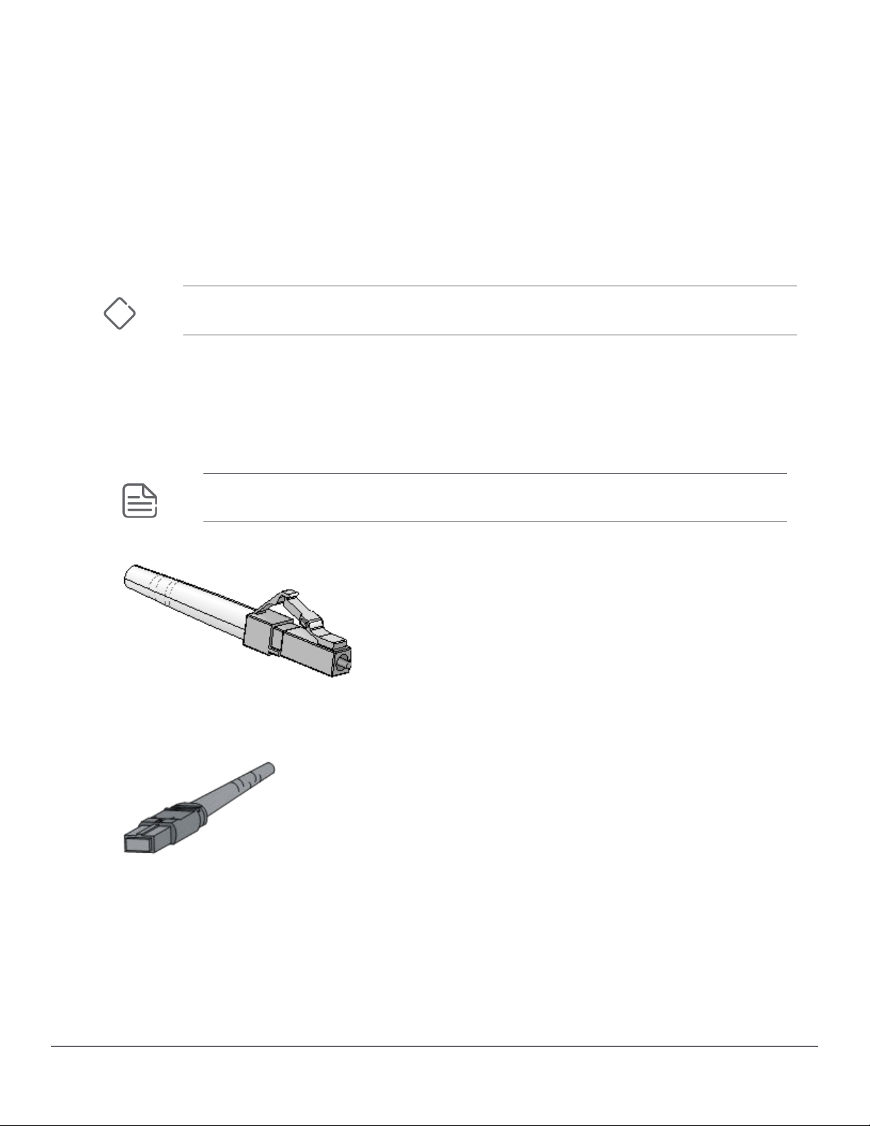
• Lucent connector or local connector (LC).
Single LC connectors (also known as Simplex) are typically used for 1G & 10G BiDi (Bidirectional) optics.
Dual LC connectors (Duplex) are typically used in normal optical types.
NOTE: 40G BiDi uses only Duplex ber versus MPO (see below) for 40G SR4 applications.
Figure 1: LC connector (a simplex connector is shown)
• Multiber Push On (MPO) connector.
Figure 2: MPO connector
The 40G QSFP+ MPO transceiver modules use only female MPO connectors, which have guide holes in
the end face of the MPO connector (the transceiver has guide pins within the MPO receptacle).
MPO connectors are classied as the following types based on the polish type:
◦ Physical contact (PC): End face polished at.
◦ Angle-polished contact (APC): End face polished with an angle, typically 8°.
10 ArubaOS-Switch and ArubaOS-CX Transceiver Guide
Page 11
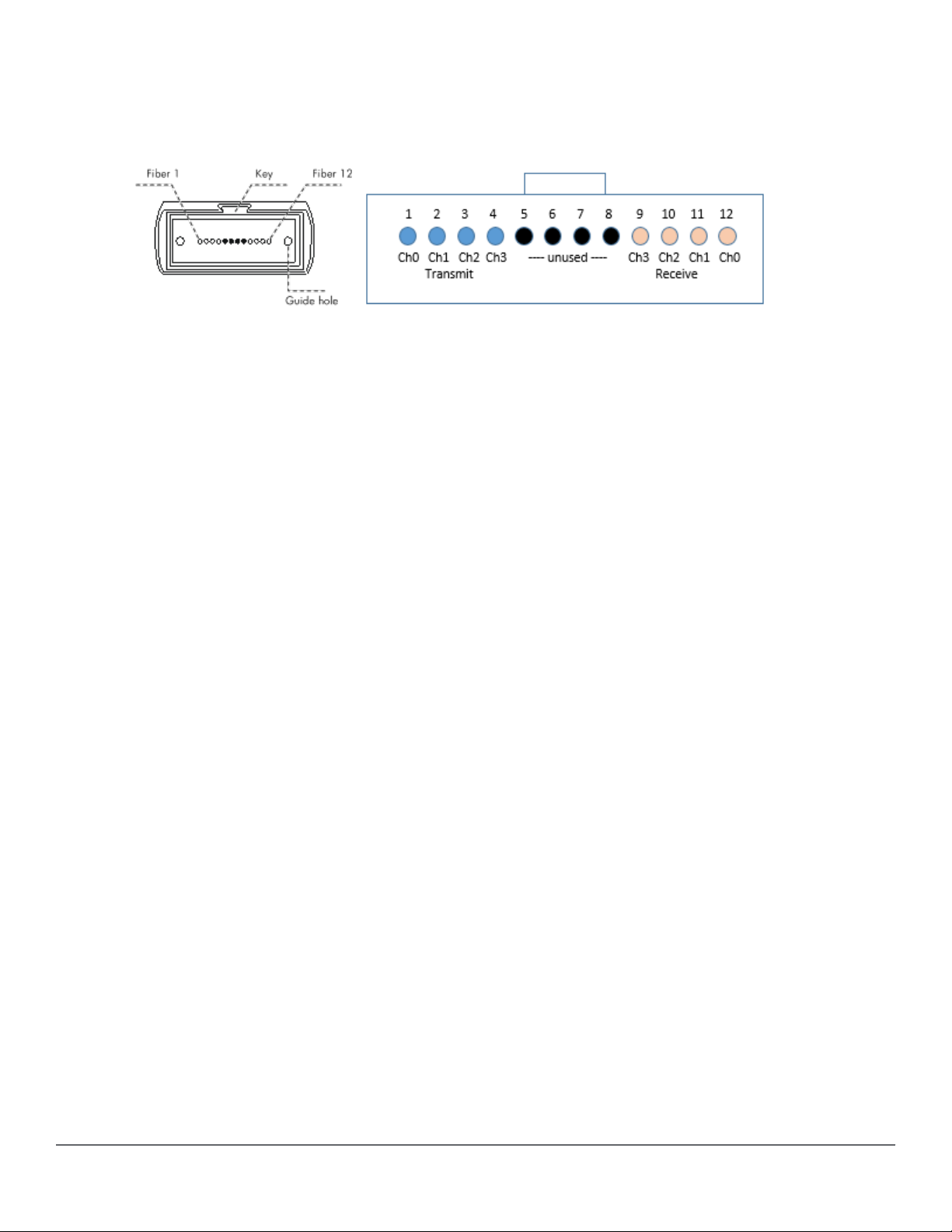
MPO connectors are available with 12 bers or 24 bers:
12-ber MPO connector (40G, SR4, eSR4, and 100G SR4 transceivers use 8 of the available 12 bers. The
four center bers are unused. )
Figure 3: End face of a 12-ber connector and channel assignment
MPO transceivers typically use four channels to communicate. These channels are assigned using the
outer eight bers (the center four are unused).
Transmit channels are one set of four bers, and the receive channels are on the other set of four bers.
Because of this, the cables used and ber cable connections from endpoint to endpoint eectively create
a crossover connection.
Be aware that using two crossover cables in series cancels this eect and no connection will be
established. An odd number of crossovers combined with straight-thru ber connections will eect a
crossover connection.
The channel layout indicates that the left four bers are Transmit, and must reach the opposite
transceiver Receive channels (and in proper channel order).
Optical parameters
This guide provides average transmit and receive power ranges for transceiver modules.
Transmit power
Transmit power is the power at which the transmitter of an optical transceiver module transmits optical
signals, in dBm.
Receive power
Receive power is the power at which the receiver of an optical transceiver module receives optical signals, in
dBm.
Use of attenuators
Transceivers are designed to transmit light pulses at a power level that accounts for loss in the ber optic
cabling, and meets the receiver input thresholds of the link partner optical transceiver.
If you are using a ber cable with less light loss than expected (for example, in a test environment and you
do not have a 40km spool of SMF available), use attenuators to aect the transmit level to within the receive
sensitivity of the other transceiver -- you will need to condition both bers (sends in both directions). If not
done, you risk overdriving the Receive end and permanently damaging the transceiver. For example, a 40G
ER4 has a highest transmit level of 4.5dBm, but the Receive Sensitivity can be no higher than -4.5dBm. That
means there must be at least a 9dBm loss on the light level to be within the standards (4.5 - (-4.5) = 9dBm
required).
Chapter 1 Overview 11
Page 12
Copper transceiver modules
Copper transceiver modules transmit signals over Category-5, -5e, -6, and -6a unshielded twisted pair (UTP).
UTP transmission cover shorter distances than ber transmission and can be used in small-sized networks
only. 10G over twisted pair requires the use of Category 6 and 6a.
Copper transceivers are supported in 1G SFP and 10G SFP+ ports where listed in the compatibility tables.
Transmission distance
Through UTP cables, signals can be transmitted over a distance of 100 m (328.08 ft.) only. This behavior
occurs because signals attenuate during transmission through the UTP cables.
Attenuation refers to the dissipation of the power of a transmitted signal as it travels over a cable.
Attenuation occurs because signal transmission suers certain resistance from the cable, which weakens
the signals as they travel over the cable. When signals are transmitted over a long distance, signal strength
decreases signicantly, causing the signal-to-noise ratio to drop below the accepted level. This decrease
makes it impossible to distinguish between signals and noise, which results in data loss.
Patch panel and punch down blocks also aect attenuation; that is, they can be a source of issues resulting
in shorter distances or data loss.
10GBASE-T connections require Category 6a as a minimum for proper 10G speeds up to the 100m distance
dictated by the IEEE 802.3ae standard for a xed 10GBASE-T port. The JL563A transceiver has a limit of 30m
max distance due to limited power available to the transceiver (vs a xed 10GBASE-T port). Anything less
(Cat 6, 5e, 5) will compromise the distance that 10G over copper can achieve.
Shielded Twisted Pair (STP) Cat 6a cable is required for full support when using the 10GBase-T transceiver
(JL563A) supported only on the 8400, 8320, and 8325 switch models. Use of STP prevents EMI events from
aecting data trac carried on the wire - known as Crosstalk or Alien Crosstalk. Large EMI events from
electronically noisy environments may be coupled onto unshielded cabling and cause temporary packet
errors. Fixed 10G ports have designs to counteract these types of bit error conditions, that the 10GBASE-T
transceiver cannot counteract consistently. Using STP Cat6a cables mitigate the errors signicantly. All
packet loss errors observed in extensive testing are considered recoverable by the host system with the
JL563A transceiver.
Connector
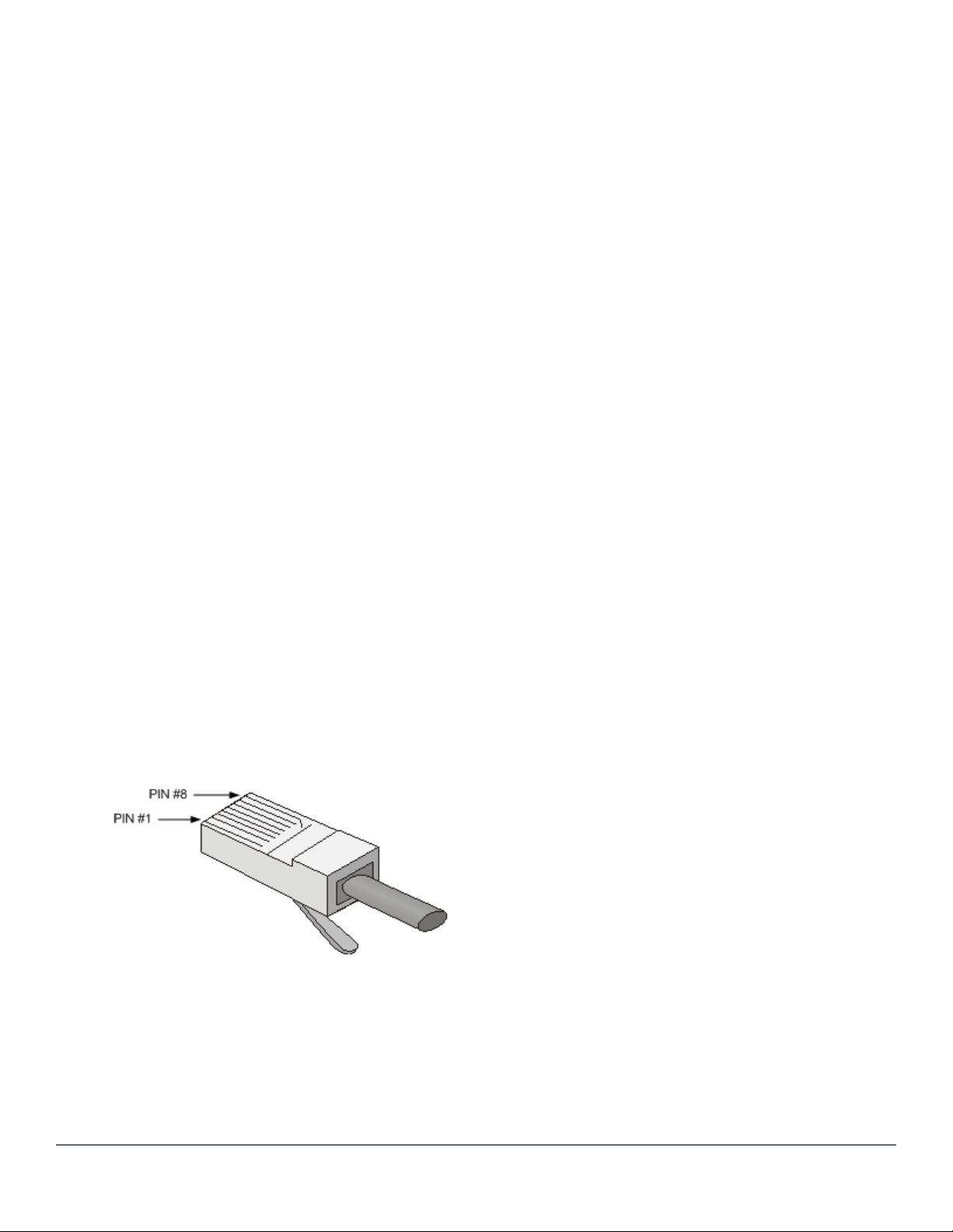
Registered Jack-45 (RJ-45) twisted-pair connectors are used as connectors for copper transceiver modules.
Figure 4: RJ-45 connector
12 ArubaOS-Switch and ArubaOS-CX Transceiver Guide
Page 13
Table 6: RJ-45 GE connector pin assignment for Gigabit connections
Pin Signal Function
1 MX_0+ Data transmit/receive
2 MX_0- Data transmit/receive
3 MX_1+ Data transmit/receive
4 MX_2+ Data transmit/receive
5 MX_2- Data transmit/receive
6 MX_1- Data transmit/receive
7 MX_3+ Data transmit/receive
8 MX_3- Data transmit/receive
Identication of 4x4 part numbers
A SKU# (also called a Product Number or Part Number) may be fullled by two or more vendor parts
providing similar functionality. A 4x4 part number is of the form nnnn-nnnn and is printed on the transceiver,
DAC, or AOC label. For example, JL309A can have a 1990-4680 or 1990-4678 4x4 part number.
4x4 part numbers are referenced in the:
• specication tables, to identify parts that support DOM (Digital Optical Monitoring) capabilities. (Some
older vendor parts do not support DOM.)
• compatibility tables, where necessary, to identify supported combinations of switch or module with the
identied transceiver, along with the minimum software version required.
In December 2017, Aruba introduced Revision D versions of 100M, 1G, and 10G products. Revision D
products are structured to be specic alternative vendors as sources for the SKU#. Earlier Revision A, B, or C
product may have alternative vendors that Aruba no longer actively ships, but remains as fully supported in
specic switches.
Some switch products will specify Revision D transceivers for full support, while other products may support
earlier (older) revision transceivers – and some with specic 4x4 part numbers.
To cross-reference the Transceiver/DAC product against the switch product to identify the minimum
software required for transceiver support, always refer to the Datasheet or QuickSpecs for the switch
product to see the current list of supported transceivers. Refer to the compatibility tables within this
document .
To use CLI commands to display data for an installed transceiver, see the following examples.
switch# show int 1/10/6 transceiver
------------------------------------------------------------
Port Type Product Serial Part
Number Number Number
------------------------------------------------------------
1/10/6 QSFP+SR4 JH231A XX57nnnnnn 1990-5555
Chapter 1 Overview 13
Page 14

switch# show int 1/10/6 dom
-------------------------------------------------------------------------------------------
Port Type Channel# Temperature Voltage Tx Bias Rx Power Tx Power
(Celsius) (Volts) (mA) (mW/dBm) (mW/dBm)
-------------------------------------------------------------------------------------------
1/10/6 QSFP+SR4 1 26.00 3.32 6.72 0.02, -16.99 0.58, -2.37
2 26.00 3.32 6.79 0.02, -16.99 0.59, -2.29
3 26.00 3.32 6.68 0.03, -15.23 0.59, -2.29
4 26.00 3.32 6.82 0.03, -15.23 0.60, -2.22
switch# show interfaces transceiver f2 detail
Transceiver in F2
Interface Index : 162
Type : QSFP+SR4
Model : JH231A
Connector Type : MPO
Wavelength : 850nm
Transfer Distance : 100m (50um OM3), 150m (50um OM4)
Diagnostic Support : DOM
Serial Number : XX57nnnnnn
Status
Temperature : 33.332C
Voltage : 3.3208V
Tx Bias Rx Power Tx Power
Channel# (mA) (mW/dbM) (mW/dbM)
--------- -------- -------------- --------------
1 6.904 0.5622, -2.501 0.5822, -2.349
2 6.706 0.5922, -2.275 0.5856, -2.324
3 6.894 0.6321, -1.992 0.5813, -2.356
4 6.792 0.5111, -2.915 0.5651, -2.479
Current Alarms:
Channel 1 :
Tx bias low alarm
Rx power low warning
Channel 2 :
Tx bias low alarm
Rx power low warning
Current Errors:
Channel 1 :
Rx Loss of Signal
Channel 2 :
Rx Loss of Signal
Channel 3 :
Rx Loss of Signal
Channel 4 :
Rx Loss of Signal
14 ArubaOS-Switch and ArubaOS-CX Transceiver Guide
Page 15

Chapter 2
QSFP28 modules
QSFP28 optical transceiver modules that use MPO connectors
See Chapter 1, "Overview", for information regarding MPO connectors and cable requirements.
Figure 5: QSFP28 optical transceiver module that use MPO connectors
Models, specications, and compatibility
QSFP28 optical transceiver modules provide a transmission rate of 100 Gbps and use MPO connectors.
Table 7: Specications for QSFP28 optical transceiver modules that use MPO connectors (1)
Product name
(SKU)
Aruba 100G
QSFP28 MPO SR4
100m 12-ber
MPO MMF
Transceiver
(JL309A)
NOTE: SR4 is not supported for use over MMF OM1 or OM2 ber. (The IEEE standard does not
state a specication.) Use MPO Female connectors (no pins) with MPO transceivers.
DOM - Digital
Optical
Monitoring
(4x4 part #)
YES
(1990-4680,
1990-4678)
Central
wl (nm)
850 MMF 50/125 2000 (OM3)
Fiber
mode
Fiber
diameter
(µm)
Modal
bandwidth
(MHz*km)
4700 (OM4)
Transmission
distance
70 m (229.66 ft)
100 m (328.08 ft)
Chapter 2 QSFP28 modules 15
Page 16

Table 8: Specications for QSFP28 optical transceiver modules that use MPO connectors (2)
Product name (SKU) Connector Optical parameters (dBm)
Transmit power Receive power
Aruba 100G QSFP28 MPO SR4
100m 12-ber MPO MMF
Transceiver (JL309A)
MPO (PC polished, 12-ber) -8.4 to +2.4 -10.3 to +2.4
Table 9: Compatibility for the QSFP28 optical transceiver modules that use MPO connectors.
Product name (SKU) Minimum software required Comments
Aruba 8325 32C models (JL626A/JL627A) 10.03.0030
Aruba 8325 48Y8C models (JL624A/
JL625A)
Aruba 8400X 6p 40G/100G QSFP28 Adv
Module (JL366A)
10.03.0030
10.00.0005 10.00.0005 provided 100G
product support.
10.00.0006 provides additional
support for 40G on the JL366A.
QSFP28 optical transceiver modules that use LC connectors
Figure 6: QSFP28 optical transceiver module that use LC connectors
Models, specications, and compatibility
QSFP28 optical transceiver modules provide a transmission rate of 100 Gbps and use LC connectors.
16 ArubaOS-Switch and ArubaOS-CX Transceiver Guide
Page 17

Table 10: Specications for QSFP28 optical transceiver modules that use LC connectors (1)
Product name
(SKU)
Aruba 100G
QSFP28 LC
CWDM4 2km SMF
Transceiver
(R0Z30A)
Aruba 100G
QSFP28 LC LR4
10km SMF 2strand
Transceiver
(JL310A)
DOM - Digital
Optical
Monitoring
(4x4 part #)
YES
(1990-4644,
1990-4643)
YES
(1990-4681)
Central wl
(nm)
Four lanes:
1264.5 to
1277.5
1284.5 to
1297.5
1304.5 to
1317.5
1324.5 to
1337.5
Four lanes:
1294.53 ~
1296.59
1299.02 ~
1301.09
Fiber
mode
SMF 9/125 N/A 2 km (1.24 miles)
SMF 9/125 N/A 10 km (6.21 miles)
Fiber
diameter
(µm)
Modal
bandwidth
(MHz*km)
Transmission
distance
Aruba 100G
QSFP28 LC ER4L
40km SMF
Transceiver
(JL743A)
1303.54 ~
1305.63
1308.09 ~
1310.19
YES Four lanes:
1294.53 to
1296.59
1299.02 to
1301.09
1303.54 to
1305.63
1308.09 to
1310.19
SMF N/A 30km (18.64
miles) without
FEC
40km (24.86
miles) Requires
FEC
Chapter 2 QSFP28 modules 17
Page 18
Table 11: Specications for QSFP28 optical transceiver modules that use LC connectors (2)
Product name (SKU) Connector Optical parameters (dBm)
Transmit power Receive power
Aruba 100G QSFP28 LC CWDM4 2km SMF
Transceiver (R0Z30A)
Aruba 100G QSFP28 LC LR4 10km SMF 2strand Transceiver (JL310A)
Aruba 100G QSFP28 LC ER4L 40km SMF
Transceiver (JL743A)
LC -6.5 to 2.5 per lane -11.5 to 2.5 per lane
LC -4.3 to +4.5 per lane -10.6 to +4.5 per
lane
LC -2.5 to 6.5 per lane -20.5 to -3.5 per
lane
Table 12: Compatibility for the QSFP28 optical transceiver modules that use LC connectors
Product name (SKU) Minimum software required Comments
Aruba 6400 (R0X26A) R0Z30A(CWDM4 2km): Not
supported
JL310A(LR4 10km): 10.04.1000
JL743A(ER4L 40km): Not
supported
Aruba 8325 32C models (JL626A/JL627A) R0Z30A (CWDM4 2km):
10.03.0030
JL310A (LR4 10km): 10.03.0030
JL743A (ER4L 40km): 10.04.0030
Aruba 8325 48Y8C models (JL624A/
JL625A)
Aruba 8400X 6p 40G/100G QSFP28 Adv
Module (JL366A)
R0Z30A (CWDM4 2km):
10.03.0030
JL310A (LR4 10km): 10.03.0030
JL743A (ER4L 40km): 10.04.0030
10.00.0005
R0Z30A (CWDM4 2km): Not
supported
JL310A (LR4 10km): 10.03.0030
JL743A (ER4L 40km): Not
supported
10.00.0005 provides support
for 100G products.
10.00.0006 provides additional
support for 40G on the JL366A.
18 ArubaOS-Switch and ArubaOS-CX Transceiver Guide
Page 19

QSFP28 DAC (copper cables)
Figure 7: QSFP28 DAC (copper cable)
Models, specications, and compatibility
Table 13: Specications for QSFP28 copper cables
Product name (SKU) Cable length Data rate Description
Aruba 100G QSFP28 to QSFP28 1m Direct
Attach Copper Cable (R0Z25A)
Aruba 100G QSFP28 to QSFP28 3m Direct
Attach Copper Cable (JL307A)
Aruba 100G QSFP28 to QSFP28 5m Direct
Attach Copper Cable (R0Z26A)
1 m (3.28 ft) 100 Gbps Used for interconnecting
100-Gigabit QSFP28 ports
3 m (9.8 ft) 100 Gbps Used for interconnecting
100-Gigabit QSFP28 ports
5 m (16.4 ft) 100 Gbps Used for interconnecting
100-Gigabit QSFP28 ports
Table 14: Compatibility for the QSFP28 copper cables
Product name (SKU) Minimum software required Comments
Aruba 8325 32C models
(JL626A/JL627A)
Aruba 8325 48Y8C models
(JL624A/JL625A)
Aruba 8400X 6p 40G/100G QSFP28 Adv
Module (JL366A)
JL307A: 10.03.0030
R0Z25A/R0Z26A: 10.04.1000
JL307A: 10.03.0030
R0Z25A/R0Z26A: 10.04.1000
JL307A: 10.00.0020
Chapter 2 QSFP28 modules 19
Page 20

QSFP+ modules
QSFP+ optical transceiver modules that use MPO connectors
See Chapter 1, " Overview", for information regarding MPO connectors and cable requirements.
Figure 8: QSFP+ optical transceiver module that uses MPO connectors
Models, specications, and compatibility
Chapter 3
QSFP+ optical transceiver modules provide a transmission rate of 40 Gbps and use Multiber Push On
(MPO) connectors.
NOTE: 40G SR4 and eSR4 are not supported for use over MMF OM1 or OM2 quality ber. (The
IEEE standard does not state a specication). Use MPO female connectors for use with the MPO
transceivers.
Table 15: Specications for QSFP+ optical transceiver modules that use MPO connectors (1)
Product name
(SKU)
HPE X142 40G
QSFP+ MPO SR4
Transceiver
(JH231A)
HPE X142 40G
QSFP+ MPO eSR4
300M XCVR
(JH233A)
DOM - Digital
Optical
Monitoring
(4x4 part #)
YES
(1990-4554)
YES
(1990-4555)
Central
wl (nm)
850 MMF 50/125 2000 (OM3)
850 MMF 50/125 2000 (OM3)
Fiber
mode
Fiber
diameter
(µm)
Modal
bandwidth
(MHz*km)
4700 (OM4)
4700 (OM4)
Transmission
distance
100 m (328.08 ft)
150 m (492.12 ft)
300 m (984.25 ft)
400 m (1312.33 ft)
20 ArubaOS-Switch and ArubaOS-CX Transceiver Guide
Page 21

Table 16: Specications for QSFP+ optical transceiver modules that use MPO connectors (2)
Product name (SKU) Connector Optical parameters (dBm)
Transmit power Receive power
HPE X142 40G QSFP+ MPO SR4
Transceiver (JH231A)
HPE X142 40G QSFP+ MPO
eSR4 300M XCVR (JH233A)
MPO (PC polished, 12-ber) –7.6 to 0 –9.5 to +2.4
MPO (PC polished, 12-ber) –7.6 to 0 –9.9 to +2.4
Table 17: Compatibility for the QSFP+ optical transceiver modules that use MPO connectors
Product name (SKU) Minimum software required Comments
Aruba 3810M/2930M 1QSFP+ 40GbE
Module (JL078A)
Aruba 3810M 24G 1-slot Switch 2QSFP
+ 40GbE Module (JL079A)
20p PoE+ / 1p 40GbE QSFP+ v3 zl2
Module (J9992A)
2p 40GbE QSFP+ v3 zl2 Module (J9996A) KB.15.17
Aruba 8320 48p SFP/SFP+ & 6p 40G
QSFP+ Switch (JL479A)
Aruba 8320 32p 40G QSFP+ Switch
(JL579A)
Aruba 8320 48p G /6p 40G QSFP+
Switch (JL581A)
All
All
KB.15.17
10.00.0006
10.00.0012
10.00.0012
Aruba 8325 32C models (JL626A/JL627A) 10.03.0030
Aruba 8325 48Y8C models (JL624A/
JL625A)
Aruba 8400X 8p 40G QSFP+ Adv Module
(JL365A)
Aruba 8400X 6p 40G/100G QSFP28 Adv
Module (JL366A)
10.03.0030
All
10.00.0006 10.00.0005 supports 100G
products.
10.00.0006 provides additional
support for 40G on the JL366A.
QSFP+ optical transceiver modules that use LC connectors
Figure 9: QSFP+optical transceiver module that uses LC connectors
Chapter 3 QSFP+ modules 21
Page 22

Models, specications, and compatibility
QSFP+ optical transceiver modules provide a transmission rate of 40 Gbps and use LC connectors.
Table 18: Specications for QSFP+ transceiver modules that use LC connectors (1)
Product name
(SKU)
Aruba 40G QSFP+
LC BiDi 150m
MMF XCVR
(JL308A)
HPE X142 40G
QSFP+ LC LR4 SM
Transceiver
(JH232A)
Aruba 40G QSFP+
LC ER4 40km SMF
Transceiver
(Q9G82A)
DOM - Digital
Optical
Monitoring
(4x4)
YES
(1990-4679)
YES
(1990-4556)
YES
(1990-4734)
Central
wl (nm)
Dual
20Gb/s:
• 850
• 900
Four
lanes:
• 1271
• 1291
• 1311
• 1331
Four
lanes:
• 1271
• 1291
Fiber
mode
MMF 50/125
SMF 9/125 N/A 10 km (6.21 miles)
SMF 9/125 N/A 30 km (18.6 miles)
Fiber
diameter
(µm)
Modal
bandwidth
(MHz*km)
2000 (OM3)
4700 (OM4)
Transmission
distance
100 m (328.08 ft)
150 m (492.12 ft)
Not supported on
OM1/OM2.
over SMF for NoFEC 40 km (24.86
miles)
• 1311
• 1331
Table 19: Specications for QSFP+ transceiver modules that use LC connectors (2)
Product name (SKU) Optical parameters (dBm)
Transmit power Receive power
Aruba 40G QSFP+ LC BiDi 150m MMF Transceiver
(JL308A)
HPE X142 40G QSFP+ LC LR4 SM Transceiver
(JH232A)
Aruba 40G QSFP+ LC ER4 40km SMF XCVR (Q9G82A) -2.7 to 4.5 dBm -21.2 to -4.5 dBm (Use
-4 to +5 -6 to +5
-7 to +2.3 per lane -13.7 to +2.3 per lane
attenuators to match
power levels.)
22 ArubaOS-Switch and ArubaOS-CX Transceiver Guide
Page 23

Table 20: Compatibility for the QSFP+ optical transceiver modules that use LC connectors
Product name (SKU) Minimum software required Comments
Aruba 3810M/2930M 1QSFP+ 40GbE
Module (JL078A)
Aruba 3810M 2QSFP+ 40GbE Module
(JL079A)
20p PoE+ / 1p 40GbE QSFP+ v3 zl2
Module (J9992A)
2p 40GbE QSFP+ v3 zl2 Module (J9996A) JH232A: KB.15.17
Aruba 8320 48p SFP/SFP+ & 6p 40G
QSFP+ Switch (JL479A)
JH232A: all
JL308A: KB.16.04.0008 or WC.
16.04.0008
Q9G82A: Not supported
JH232A: all
JL308A: KB.16.04.0008
Q9G82A: Not supported
JH232A: KB.15.17
JL308A: KB.16.04.0008
Q9G82A: Not supported
JL308A: KB.16.04.0008
Q9G82A: Not supported
JH232A: 10.00.0006
JL308A: 10.00.0006
The JL079A module is not
supported in the 2930M series
nor on the 3810M 16SFP+ 2slot switch (JL075A).
Q9G82A: 10.00.0018
Aruba 8320 32p 40G QSFP+ Switch
(JL579A)
Aruba 8320 48p G /6p 40G QSFP+
Switch (JL581A)
Aruba 8325 32C models (JL626A/JL627A) 10.03.0030
Aruba 8325 48Y8C models (JL624A/
JL625A)
JH232A: 10.00.0012
JL308A: 10.00.0012
Q9G82A: 10.00.0018
JH232A: 10.00.0012
JL308A: 10.00.0012
Q9G82A: 10.00.0018
10.03.0030
Table Continued
Chapter 3 QSFP+ modules 23
Page 24

Product name (SKU) Minimum software required Comments
Aruba 8400X 8p 40G QSFP+ Adv Module
(JL365A)
Aruba 8400X 6p 40G/100G QSFP28 Adv
Module (JL366A)
JH232A: all
JL308A: all
Q9G82A: 10.00.0018
JH232A: 10.00.0006
JL308A: 10.00.0006
Q9G82A: 10.00.0018
QSFP+ DAC (copper cables)
Figure 10: QSFP+ DAC copper cables
10.00.0005 provides support
for 100G products.
10.00.0006 provides additional
support for 40G on the JL366A.
IMPORTANT: Direct Attach over Copper (DAC) cables have a minimum bend radius of typically
4x the diameter of the cable (approximately a 1" bend radius). Handle DAC cables carefully to
ensure that you do not crimp or bend the cable beyond a 1" radius. Otherwise, you risk
damaging the cable.
Models, specications, and compatibility
Table 21: Specications for QSFP+ copper cables
Product name (SKU) Cable length Data rate
HPE X242 40G QSFP+ to QSFP+ 1m DAC Cable (JH234A) 1 m (3.28 ft)
HPE X242 40G QSFP+ to QSFP+ 3m DAC Cable (JH235A) 3 m (9.84 ft)
HPE X242 40G QSFP+ to QSFP+ 5m DAC Cable (JH236A) 5 m (16.40 ft)
40 Gbps
24 ArubaOS-Switch and ArubaOS-CX Transceiver Guide
Page 25

Table 22: Compatibility for the QSFP+ copper cables
Product name (SKU) Minimum software required Comments
Aruba 3810M/2930M 1QSFP+ 40GbE
Module (JL078A)
Aruba 3810M 2QSFP+ 40GbE Module
(JL079A)
20p PoE+ / 1p 40GbE QSFP+ v3 zl2
Module (J9992A)
2p 40GbE QSFP+ v3 zl2 Module (J9996A) KB.15.17
Aruba 8320 48p 10G SFP/SFP+ and 6p
40G QSFP+ Switch (JL479A)
Aruba 8320 32p 40G QSFP+ Switch
(JL579A)
Aruba 8320 48p G /6p 40G QSFP+
Switch (JL581A)
Aruba 8325 32C models (JL626A/JL627A) 10.03.0030
Aruba 8325 48Y8C models (JL624A/
JL625A)
All
All The JL079A module is not
KB.15.17
All
10.00.0012
10.00.0012
10.03.0030
supported in the 2930M
series nor on the 3810M
16SFP+ 2-slot Switch
(JL075A).
Aruba 8400X 8p 40G QSFP+ Adv Module
(JL365A)
Aruba 8400X 6p 40G/100G QSFP28 Adv
Module (JL366A)
All
10.00.0006
Chapter 3 QSFP+ modules 25
Page 26

QSFP+ 40G AOC (Active Optical Cable)
Figure 11: QSFP+ 40G AOC (Active Optical Cable)
Models, specications, and compatibility
Table 23: Specications for QSFP+ 40G active optical cables
Product name (SKU) Cable length Data rate
Aruba 40G QSFP+ to QSFP+ 7m AOC (R0Z22A) 7m (22.96 ft)
Aruba 40G QSFP+ to QSFP+ 15m AOC (R0Z23A) 15m (49.21 ft)
Aruba 40G QSFP+ to QSFP+ 30m AOC (R0Z24A) 30m (98.42 ft)
40 Gbps
Table 24: Compatibility for the QSFP+ 40G active optical cables
Product name (SKU) Minimum software required Comments
8325 Switch Series (JL624A, JL625A) 10.03.0040
26 ArubaOS-Switch and ArubaOS-CX Transceiver Guide
Page 27

Chapter 4
SFP28 modules
SFP28 optical transceiver modules
SFP28 ports are 25G speed ports and similar in size to a 10G SFP+ or 1G SFP port. They have supporting
circuitry to enable 25G speed transceiver, DAC, and AOC components.
Although 10G and 1G transceiver products may 't' into an SFP28 port, the particular switch model or
module may be limited in supporting lower speeds.
See Chapter 1, "Overview" for information regarding the type of connectors used by SFP28 port products.
Always refer to the Datasheet or QuickSpecs for the Switch product to see the current list of supported
transceivers.
Figure 12: SFP28 optical transceiver modules
Models, specications, and compatibility
SFP28 optical transceiver modules provide a transmission rate of 25 Gbps and use LC connectors.
Table 25: Specications for SFP28 optical transceiver modules (1)
Product name (SKU) DOM-
Digital
Optical
Monitoring
(4x4 part
number)
Aruba 25G SFP28 LC SR
100m MMF XCVR (JL484A)
Aruba 25G SFP28 LC eSR
400m MMF XCVR (JL485A)
Yes (partial) 850 MMF 50/125 2000
Yes (partial) 850 MMF 50/125 2000
Central
wl (nm)
Fiber
mode
Fiber
Diamet
er
Modal
bandwi
dth
(MHz*k
m)
(OM3)
4700
(OM4)
(OM3)
Transmission
distance
70m (229.66 ft)
100m (328.08 ft)
300m (229.66 ft)
Table Continued
Chapter 4 SFP28 modules 27
Page 28

Product name (SKU) DOM-
Digital
Optical
Monitoring
(4x4 part
number)
Central
wl (nm)
Fiber
mode
Fiber
Diamet
er
Modal
bandwi
dth
(MHz*k
m)
Transmission
distance
Aruba 25G SFP28 LC LR
10km SMF Transceiver
(JL486A)
Yes (partial) 1310 SMF 9/125 n/a 10km (6.21 miles)
Table 26: Specications for SFP28 optical transceiver modules (2)
Product name (SKU) Optical parameters (dBm)
Transmit power Receive power
Aruba 25G SFP28 LC SR 100m MMF XCVR
(JL484A)
Aruba 25G SFP28 LC eSR 400m MMF XCVR
(JL485A)
Aruba 25G SFP28 LC LR 10km SMF
Transceiver (JL486A)
-8.4 to +2.4 -10.3 to +2.4
-8.4 to +2.4 -10.3 to +2.4
-7.0 to +2.0 -13.3 to +2.0
Table 27: Compatibility for the SFP28 transceiver modules
Product name SKU
Minimum software
required
4700
(OM4)
400m (328.08 ft)
Comments
Aruba 6300 series All models M and F 10.04.0001
Aruba 6400 modules
with SFP56 ports
8325 Switch Series JL624A, JL625A 10.03.0001
Aruba 8325 48Y8C
models
R0X39A, R0X40A, R0X41A,
R0X42A, R0X43A, R0X44A
JL624A, JL625A 10.03.0030
10.04.0001
SFP28 DAC (copper cables)
Always refer to the Datasheet or QuickSpecs for the Switch product to see the current list of supported
transceivers.
Figure 13: SFP28 DAC copper cable
28 ArubaOS-Switch and ArubaOS-CX Transceiver Guide
Page 29

IMPORTANT:
Direct Attach over Copper (DAC) cables have a minimum bend radius of typically 4x the
diameter of the cable (approximately a 1" bend radius). Handle DAC cables carefully to ensure
that you do not crimp or bend the cable beyond a 1" radius. Otherwise, you risk damaging the
cable.
Models, specications, and compatibility
Table 28: Specications for SFP28 copper cables
Product name (SKU) Cable length Data rate
Aruba 25G SFP28 to SFP28 0.65m DAC Cable
(JL487A)
Aruba 25G SFP28 to SFP28 3m DAC Cable
(JL488A)
Aruba 25G SFP28 to SFP28 5m DAC Cable
(JL489A)
The following DAC cables are oered by HPE Servers and Systems and ordered using the specied part
number (these cables may not be available to order for Aruba-only partners). See the SERVER NETWORKING
TRANSCEIVER AND CABLE COMPATIBILITY MATRIX for compatibility with HPE interconnect products (on
hpe.com, search for "server networking transceiver and cable compatibility support matrix").
0.65m (2.13 ft)
3m (9.84 ft)
5m (16.40 ft)
25 Gbps
Table 29: Specications for HPE SFP28 copper cables
Product name (SKU) Cable length Data rate
HPE 25Gb SFP28 to SFP28 3m DAC (844477-B21) 3m (9.84 ft)
HPE 25Gb SFP28 to SFP28 5m DAC (844480-B21) 5m (16.40 ft)
25 Gbps
Chapter 4 SFP28 modules 29
Page 30

Table 30: Compatibility for the SFP28 DAC copper cables
Minimum software
Product name SKU
required
JL487A, JL488A, JL489A
Comments
6300 Switch Series (M
and F)
6400 modules with
SFP56 ports
8325 48Y8C models JL624A, JL625A 10.03.0030
All models 10.04.0001
844477-B21 & 844480B21: not supported
R0X39A, R0X40A, R0X41A,
R0X42A, R0X43A, R0X44A
10.04.0001
844477-B21 & 844480B21: not supported
844477-B21 & 844480B21: 10.04.0040
SFP28 25G AOC (Active Optical Cable)
Figure 14: SFP28 25G AOC (Active Optical Cable)
844477-B21 & 844480B21: veried against HPE
interconnects: 817749B21, 817753-B21,
867334-B21, 867328-B21,
817709-B21, 817718-B21
30 ArubaOS-Switch and ArubaOS-CX Transceiver Guide
Page 31

Models, specications, and compatibility
Table 31: Specications for SFP28 25G active optical cables
Product name (SKU) Cable length Data rate
Aruba 25G SFP28 to SFP28 3m AOC (R0M44A) 3m (9.84 ft)
25 GbpsAruba 25G SFP28 to SFP28 7m AOC (R0M45A) 5m (16.40 ft)
Aruba 25G SFP28 to SFP28 15m AOC (R0Z21A) 15m (49.21 ft)
Table 32: Compatibility for the SFP28 25G active optical cables
Product Name SKU Minimum software
required R0M44A,
R0M45A, R0Z21A
8325 Switch Series JL624A, JL625A 10.03.0040
Comments
Chapter 4 SFP28 modules 31
Page 32

Chapter 5
SFP+ modules
SFP+ optical transceiver modules
In December 2017, Aruba introduced Revision D versions of 100M, 1G, and 10G transceivers. Revision D
products are structured to be specic alternate vendors as sources for the SKU#. Earlier Revision A, B, or C
product may have alternate vendors that we no longer actively ship, but remain as fully supported in earlier
and current products.
Some switch products will be specifying Revision D or Revision E (as is the case for the 8325 requiring J9151E
or later) transceivers for full support, while other products may support earlier (older) revision transceivers –
and some with specic 4x4 part numbers (see Chapter 1, "Overview", for information regarding 4x4 part
numbers).
Always refer to the Datasheet or QuickSpecs for the Switch product to see the current list of supported
transceivers.
Figure 15: SFP+ optical transceiver modules
NOTE:
• Although a 10G SFP+ transceiver module is the same physical dimensions of a 1G SFP
transceiver, a 10G transceiver will NOT operate in a 1G SFP port.
• Many, although not all, 10G SFP+ ports have support to use a 1G SFP transceiver (or even a
100Mbps FX SFP transceiver).
See the QuickSpec for the Switch product and verify if the 1G or 100Mbps SFP transceiver is
supported in the 10G SFP+ port.
Models, specications, and compatibility
SFP+ optical transceiver modules provide a transmission rate of 10.31 Gbps and use LC connectors.
The specications for Revision D and E transceiver products are the same as the specied Revision A, B, C
SKUs. Where support for a Revision A, B, or C transceiver existed, Revision D or E parts are also supported.
32 ArubaOS-Switch and ArubaOS-CX Transceiver Guide
Page 33

Table 33: Specications for SFP+ optical transceiver modules (1)
Product Name
(SKU)
HPE X132 10G SFP+
LC SR Transceiver
(J9150A)
Aruba 10G SFP+ LC
SR 300m MMF XCVR
(J9150D)
HPE X132 10G SFP+
LC LRM Transceiver
(J9152A)
Aruba 10G SFP+ LC
LRM 220m MMF
XCVR (J9152D)
DOM - Digital
Optical
Monitoring
(4x4 part #)
Yes
(1990-4391,
1990-4175)
1990-4635
1990-4634
Yes
(1990-4485)
Central
wl (nm)
850 MMF 50/125 4700 (OM4)
1310 MMF 50/125 1500
Fiber
mode
Fiber
diameter
(µm)
62.5/125 200 (OM1)
62.5/125 200 (OM1)
Bandwidth
(MHz*km)
2000 (OM3)
500 (OM2)
400
160
500 (OM2)
400
160
Transmission
distance
400 m (1312.34 ft)
300 m (984.25 ft)
82 m (269.03 ft)
66 m (216.54 ft)
33 m (108.27 ft)
26 m (85.30 ft)
220 m (721.78 ft)
220 m (721.78 ft)
100 m (328.08 ft)
220 m (721.78 ft)
220 m (721.78 ft)
HPE X132 10G SFP+
LC LR Transceiver
(J9151A)
Aruba 10G SFP+ LC
LR 10km SMF XCVR
(J9151D and J9151E)
HPE X132 10G SFP+
LC ER Transceiver
(J9153A)
Aruba 10G SFP+ LC
ER 40km SMF XCVR
(J9153D)
NOTE: J9152D 10G LRM (Long Reach Multimode) with 4x4 1990-4485 does not require a Mode
Conditioning Patch (MCP) cable. Older J9151A with 4x4 numbers other than 1990-4485 may
require an MCP when you use OM1 or OM2 ber cables. Never use mode conditioning patch
cables for OM3 or OM4 ber types. For more information about mode conditioning patch
cables, see related sections in the IEEE 802.3 standard.
Yes
(1990-4657,
1990-4694)
Yes
(1990-4365,
1990-4656)
SMF 9/125 N/A 300m (987.25 ft)
1310 SMF 9/125 N/A 10 km (6.21 miles)
1550 SMF 9/125 N/A 40 km (24.86
miles)
Chapter 5 SFP+ modules 33
Page 34

Table 34: Specications for SFP+ optical transceiver modules (2)
Product name (SKU) Optical parameters (dBm)
Transmit power Receive power
HPE X132 10G SFP+ LC SR Transceiver (J9150A)
Aruba 10G SFP+ LC SR 300m MMF XCVR (J9150D)
HPE X132 10G SFP+ LC LRM Transceiver (J9152A)
Aruba 10G SFP+ LC LRM 220m MMF XCVR (J9152D)
HPE X132 10G SFP+ LC LR Transceiver (J9151A)
Aruba 10G SFP+ LC LR 10km SMF XCVR (J9151D/J9151E)
HPE X132 10G SFP+ LC ER Transceiver (J9153A)
Aruba 10G SFP+ LC ER 40km SMF XCVR (J9153D)
–7.3 to –1 –9.9 to +0.5
–6.5 to +0.5 –6.5 to +1.5
–8.2 to +0.5 –14.4 to +0.5
–4.7 to +4 –15.8 to –1
Table 35: Compatibility for the SFP+ optical transceiver module
Product name SKU Minimum software required Comments
1850 Switch Series JL169A
10G-SR, LR, LRM
(J9150A/J9150D,
J9151A/J9151D/J9151E,
J9152A/J9152D)
J9150A/J9150D: All
J9151A/J9151D: All
J9152A/J9152D: All
10G-ER (J9153A/
J9153D)
J9153A/J9153D is
not supported
on the 1850
Switch Series.
Unlisted models do
not have SFP+ ports.
2530 Switch Series J9853A, J9854A,
J9855A, J9856A
2540 Switch Series JL354A, JL355A,
JL356A, JL357A
2910al Switch Series J9008A All W.15.07.0002 Unlisted models do
2920 Switch Series J9726A, J9727A,
J9728A, J9729A,
J9836A
All All Unlisted models lack
SFP+ ports.
All (J9150A/J9150D and
J9151A/J9151D only)
J9152A/J9152D (LRM) is
not supported in any
2540 model
All For use in an
All J9152A/J9152D (LRM)
is not supported in
any 2540 model.
not have SFP+ ports.
installed J9731A
Aruba 2920 2-port
10GbE SFP+ Module.
Table Continued
34 ArubaOS-Switch and ArubaOS-CX Transceiver Guide
Page 35

Product name SKU Minimum software required Comments
2930F Switch Series JL253A, JL254A,
JL255A, JL256A,
JL258A, JL263A,
JL264A, JL558A,
JL559A
2930M Switch Series JL319A, JL320A,
JL321A, JL322A,
JL323A, JL324A
R0M67A,
R0M68A
3500yl Switch Series J8692A, J8693A,
J9310A, J9311A
10G-SR, LR, LRM
(J9150A/J9150D,
J9151A/J9151D/J9151E,
J9152A/J9152D)
All (J9150A/J9150D and
J9151A/J9151D/J9151E
only)
J9152A/J9152D (LRM) is
not supported in any
2930F model
All All For use in an
WC.16.05 WC.16.05
K.14.50 and later K.15.02.0004
10G-ER (J9153A/
J9153D)
All
and later
Unlisted models lack
SFP+ ports.
J9152A/J9152D (or
any 10G LRM
technology) is not
supported in any
2930F model.
installed JL083A
Aruba 3810M/2930M
4SFP+ MACsec
Module.
For use in an
installed J9312A
10GbE 2-port SFP
+/2-port CX4 yl
Module.
3800 Switch Series J9575A, J9576A,
J9573A, J9574A,
J9584A
3810M Switch Series JL071A, JL072A,
JL073A, JL074A,
JL076A
JL075A All All For use in the JL075A
All All Unlisted models do
not have SFP+ ports.
All All For use in an
installed JL083A
Aruba 3810M/2930M
4SFP+ MACsec
Module
SFP+ ports or in an
installed JL083A
Aruba 3810M/2930M
4SFP+ MACsec
Module
Table Continued
Chapter 5 SFP+ modules 35
Page 36

Product name SKU Minimum software required Comments
10G-SR, LR, LRM
(J9150A/J9150D,
J9151A/J9151D/J9151E,
J9152A/J9152D)
5400zl Switch Series J9309A K.14.39 K.15.02.0004
J9538A, J9548A,
J9536A
5400R Switch Series J9538A, J9548A,
J9536A
J9990A, J9993A KB.15.17 KB.15.17
K.15.02.0004 K.15.02.0004
All All
10G-ER (J9153A/
J9153D)
The J9309A 4-port
SFP+ module
supports only 10G
transceivers.
10G ER (J9153A/D)
transceivers are
limited to a
maximum of two
transceivers per
J9309A or J9538A
modules when used
in a 5400zl or 8200zl
chassis.
6120 Switch Series 516733-B21
(6120XG)
6200yl Switch Series J8992A K.14.50 K.15.02.0004
All Not supported 498358-B21
(6120G/XG) has 1GB
SFP and 10G XFP or
CX4 ports and does
not support these
SFP+ transceivers.
J8992A xed SFP
ports are 1GB and
do not support these
SFP+ transceivers.
For use in an
installed J9312A
10GbE 2-port SFP
+/2-port CX4 yl
Module.
Table Continued
36 ArubaOS-Switch and ArubaOS-CX Transceiver Guide
Page 37

Product name SKU Minimum software required Comments
6300 Switch Series All models (M
and F)
10G-SR, LR, LRM
(J9150A/J9150D,
J9151A/J9151D/J9151E,
J9152A/J9152D)
10.04.0001
10G-ER (J9153A/
J9153D)
10.04.0001
J9153A/J9153D
• 1990-4365
• 1990-4656
J9152A/J9152D (or
any 10G LRM
technology) is not
supported in the
6300/6400 series
J9150A/J9150D
• 1990-4391
• 1990-4175
• 1990-4635
• 1990-4634
J9151A/J9151D
• 1990-4657
• 1990-4727
• 1990-4694
J9151E
• 1990-4727
• 1990-4694
Table Continued
Chapter 5 SFP+ modules 37
Page 38

Product name SKU Minimum software required Comments
6400 modules with
SFP56 or SFP+ ports
R0X39A, R0X40A,
R0X41A, R0X42A,
R0X43A, R0X44A
10G-SR, LR, LRM
(J9150A/J9150D,
J9151A/J9151D/J9151E,
J9152A/J9152D)
10.04.0001
10G-ER (J9153A/
J9153D)
10.04.0001
J9153A/J9153D
• 1990-4365
• 1990-4656
J9152A/J9152D (or
any 10G LRM
technology) is not
supported in the
6300/6400 series
J9150A/J9150D
• 1990-4391
• 1990-4175
• 1990-4635
• 1990-4634
J9151A/J9151D
• 1990-4657
• 1990-4727
• 1990-4694
J9151E
• 1990-4727
• 1990-4694
6600 Switch Series J9264A, J9265A K.14.03 K.15.02.0004
J9452A K.14.24 K.15.02.0004
8200zl Switch Series J9309A K.14.39 K.15.02.0004 The J9309A four-port
SFP+ module only
supports 10G
transceivers.
J9538A, J9548A,
J9536A
K.15.02.0004 K.15.02.0004 10G ER ( J9153A/D)
transceivers are
limited to a
maximum of two
transceivers per
J9309A or J9538A
modules when used
in a 5400zl or 8200zl
chassis.
Table Continued
38 ArubaOS-Switch and ArubaOS-CX Transceiver Guide
Page 39

Product name SKU Minimum software required Comments
Aruba 8320 48p 10G
SFP/SFP+ and 6p
40G QSFP+ Switch
JL479A
10G-SR, LR, LRM
(J9150A/J9150D,
J9151A/J9151D/J9151E,
J9152A/J9152D)
All (J9150A/J9150D and
J9151A/J9151D only)
J9152A/J9152D (LRM) is
not supported in the
8320 switches.
10G-ER (J9153A/
J9153D)
All
Only the following
4x4 part numbers
are supported:
• J9150A/J9150D:
1990-4391,
1990-4175,1990-463
5, 1990-4634
• J9151A/J9151D:
1990-4657,
1990-4727,
1990-4694
• J9151E: 1990-4727,
1990-4694
• J9153A/J9153D:
1990-4365,
1990-4656
J9152A/J9152D (or
any 10G LRM
technology) is not
supported in the
8320 Switches.
Table Continued
Chapter 5 SFP+ modules 39
Page 40
Product name SKU Minimum software required Comments
Aruba 8325 48Y8C
Switch
JL624A, JL625A
10G-SR, LR, LRM
(J9150A/J9150D,
J9151A/J9151D/J9151E,
J9152A/J9152D)
10.03.0030
J9125A/J9152D (or any
10G LRM technology) is
not supported in the
8325 switches.
10G-ER (J9153A/
J9153D)
10.03.0030
J9153A/J9153D
• 1990-4365
• 1990-4656
J9150A/J9150D
• 1990-4391
• 1990-4175
• 1990-4635
• 1990-4634
8325 is only
compatible with
J9151E or later. Do
not attempt to use
J9151D or earlier.
J9151E
• 1990-4727
• 1990-4694
Aruba 8400X
modules
JL363A All JL363A: All
J9125A/J9152D (or
any 10G LRM
technology) is not
supported in the
8325 switches.
The 8325 requires
conguration of
"interface groups" to
enable use of 1G or
10G transceivers or
DACs in the SFP28
ports (default is to
use 25G
transceivers/DACs).
See the Installation
Guide for details.
Only the following
4x4 part numbers
are supported:
• J9150A/J9150D:
1990-4391,
1990-4175,
40 ArubaOS-Switch and ArubaOS-CX Transceiver Guide
Page 41

Product name SKU Minimum software required Comments
10G-SR, LR, LRM
(J9150A/J9150D,
J9151A/J9151D/J9151E,
J9152A/J9152D)
NOTE: J9152D 10G LRM with 4x4 1990-4485 does not require the use of a mode conditioning
patch (MCP) cable. Older J9151A with 4x4 #s other than 1990-4485 may require an MCP when
you use OM1 or OM2 ber cables. Never use mode conditioning patch cables for OM3 or OM4
ber types. For more information about mode conditioning patch cables, see related parts in
the IEEE 802.3 standard.
10G-ER (J9153A/
J9153D)
1990-4635,
1990-4634
• J9151A/J9151D:
1990-4657,
1990-4727,
1990-4694
• J9151E:
1990-4727,
1990-4694
• J9152A/J9152D:
1990-4485
• J9153A/J9153D:
1990-4365,
1990-4656
10G SFP+ copper transceiver modules
Figure 16: 10G SFP+ copper transceiver module
Models, specications, and compatibility
Table 36: Specications for SFP+ copper transceiver modules
Product name (SKU) Transmission
distance
Aruba 10GBASE-T SFP+ RJ45 30m
Cat6A XCVR (JL563A)
30 m (98.43 ft) 10G STP Cat6A 1RJ-45
Data rate Cable type Connector
type
Chapter 5 SFP+ modules 41
Page 42

1
See Transmission distance.
Table 37: Compatibility for SFP+ copper transceiver modules
Product name SKU Minimum software
required (JL563A)
Aruba 6300 with SFP+/SFP28/
SFP56 ports
Aruba 6400 modules with SFP+ or
SFP56 ports
Aruba 8320 48p 10G SFP/SFP+
and 6p 40G QSFP+ Switch
Aruba 8325 48Y8C JL624A , JL625A 10.03.0030 JL563A does not support 1G
All models M
and F
R0X39A, R0X40A,
R0X41A, R0X42A,
R0X43A, R0X44A
JL479A 10.01.0011 JL563A does not support 1G
10.04.0001
10.04.0001
Comments
operation; only 10G. It is only
supported in ports 1 – 12. A
maximum of 12 JL563A
transceivers can be used in a
switch.
operation; only 10G.
It is only supported in the
top two rows, ports 1 – 17. It
is disallowed in ports 3, 6, 9,
12, and 15. Use in any other
port generates an
incompatible interface
error (meaning the port does
not support the use of this
transceiver; move the
transceiver to another port.
Aruba 8400X 32p 10G SFP/SFP+
Msec Module
SFP+ DAC cables
Figure 17: SFP+ DAC cable
A maximum of 12 JL563A
transceivers can be used in a
switch.
JL363A 10.00.0018 JL563A does not support 1G
operation; only 10G. It is only
supported in ports 1 – 12. A
maximum of 12 JL563A
transceivers can be used in a
line card.
42 ArubaOS-Switch and ArubaOS-CX Transceiver Guide
Page 43
IMPORTANT: Direct Attach over Copper (DAC) cables have a minimum bend radius of typically
4x the diameter of the cable (approximately a 1" bend radius). Handle DAC cables carefully to
ensure that you do not crimp or bend the cable beyond a 1" radius, otherwise, you risk
damaging the cable.
Models, specications, and compatibility
specications for Revision D transceiver products are the same as the specied Revision A, B, and C
The
SKUs. Where support for a Revision A, B, or C transceiver existed, Revision D parts are also supported.
Table 38: Specications for SFP+ DAC cables
Product name (SKU) Cable length Data rate
HPE X242 10G SFP+ to SFP+ 1m DAC Cable (J9281B)
Aruba 10G SFP+ to SFP+ 1m DAC Cable (J9281D)
HPE X242 10G SFP+ to SFP+ 3m DAC Cable (J9283B)
Aruba 10G SFP+ to SFP+ 3m DAC Cable (J9283D)
HPE X242 10G SFP+ to SFP+ 7m DAC Cable (J9285B)
Aruba 10G SFP+ to SFP+ 7m DAC Cable (J9285D)
The following DAC cables are oered by HPE Servers and Systems and ordered using the specied part
number (these cables may not be available to order for Aruba-only partners). See the SERVER NETWORKING
TRANSCEIVER AND CABLE COMPATIBILITY MATRIX for compatibility with HPE interconnect products (on
hpe.com, search for "server networking transceiver and cable compatibility support matrix").
1 m (3.28 ft)
3 m (9.84 ft)
10.31 Gbps
7 m (22.97 ft)
Table 39: Specications for HPE SFP28 copper cables
Product name (SKU) Cable length Data rate
HPE BLc 10G SFP+ SFP+ 3m DAC Cable(487655B21)
HPE BLc 10G SFP+ SFP+ 5m DAC Cable (537963B21)
3m (9.84 ft)
10 Gbps
5m (16.40 ft)
Table 40: Compatibility for the SFP+ copper cables
Product name SKU Minimum software required
(J9281B/J9281D, J9283B/J9283D,
J9285B/J9285D)
1850 Switch Series JL169A All Unlisted models lack SFP+
2530 Switch Series J9853A, J9854A,
J9855A, J9856A
2540 Switch Series JL354A, JL355A,
JL356A, JL357A
Chapter 5 SFP+ modules 43
All Unlisted models do not
All (J9281B/J9281D and J9283B/
J9283D only. See comments for
exception)
Comments
ports.
have SFP+ ports.
J9285B/J9285D or any type
of 7m DAC is not supported
in any of these series.
Table Continued
Page 44

Product name SKU Minimum software required
(J9281B/J9281D, J9283B/J9283D,
J9285B/J9285D)
Comments
2910al Switch Series J9145A, J9146A,
J9147A, J9148A
2920 Switch Series J9726A, J9727A,
J9728A, J9729A,
J9836A
2930F Switch Series JL253A, JL254A,
JL255A, JL256A,
JL258A, JL263A,
JL264A, JL558A,
JL559A
2930M Switch Series JL319A, JL320A,
JL321A, JL322A,
JL323A, JL324A
3500yl Switch Series J8692A, J8693A,
J9310A, J9311A
W.14.28 For use in the J9008A 2-port
10GbE SFP+ al module.
All The SFP ports on the
models listed do not
support these 10G SFP+
cables. For use in an
installed J9731A Aruba 2920
2-port 10GbE SFP+ .
All (J9281B/J9281D and J9283B/
J9283D only. See comment for
exception)
All
K.14.50 For use in an installed
Unlisted models lack 10G
SFP+ ports.
J9285B/J9285D or any type
of 7m DAC is not supported
in any of these series.
For use in an installed
JL083A Aruba 3810M/2930M
4SFP+ MACsec Module
J9285B/9285D (7m DAC) is
supported in all 2930M
models.
J9312A 10GbE 2-port SFP
+/2-port CX4 yl Module.
3800 Switch Series J9575A, J9576A,
J9573A, J9574A,
J9584A
3810M Switch Series JL071A, JL072A,
JL073A, JL074A,
JL076A
JL075A All For use in the JL075A SFP+
5400zl Switch Series J9309A K.14.39 The J9309A 4-port SFP+
J9538A, J9548A,
J9536A
5400R Switch Series J9538A, J9548A,
J9536A
J9990A, J9993A KB.15.17
6120 Switch Series 516733-B21 All
All Unlisted models not lack
SFP+ ports.
All For use in an installed
JL083A Aruba 3810M/2930M
4SFP+ MACsec Module.
ports or used in an installed
JL083A Aruba 3810M/2930M
4SFP+ MACsec Module.
module only supports 10G
transceivers.
K.15.02.0004
All
Table Continued
44 ArubaOS-Switch and ArubaOS-CX Transceiver Guide
Page 45

Product name SKU Minimum software required
(J9281B/J9281D, J9283B/J9283D,
J9285B/J9285D)
6200yl Switch Series J8992A K.14.50 J8992A xed SFP ports are
6300 Switch Series
All models M and F
10.04.0001
Comments
1GB and do not support
these SFP+ copper cables.
For use in an installed
J9312A 10GbE 2-port SFP
+/2-port CX4 yl Module.
J9285B/J9285D or any type
of 7m DAC is not supported
in any 6300 model.
J9281B/J9281D
• 8121-1151
• 8121-1300
J9283B/J9283D
• 8121-1152
• 8121-1298
6400 Modules with
SFP+ or SFP56 ports
6600 Switch Series J9264A, J9265A,
R0X39A, R0X40A,
R0X41A, R0X42A,
R0X43A, R0X44A
J9452A
10.04.0001
K.14.32
J9285B/J9285D or any type
of 7m DAC is not supported
in any SFP56 port.
J9281B/J9281D
• 8121-1151
• 8121-1300
J9283B/J9283D
• 8121-1152
• 8121-1298
J9285B/J9285D
Only supported in SFP+
ports on R0X43A
• 8121-1154
• 8121-1305
8200zl Switch Series J9309A K.14.39 The J9309A 4-port SFP+
module only supports 10G
transceivers.
Table Continued
Chapter 5 SFP+ modules 45
Page 46

Product name SKU Minimum software required
(J9281B/J9281D, J9283B/J9283D,
J9285B/J9285D)
Comments
Aruba 8320 48p 10G
SFP/SFP+ and 6p 40G
QSFP+ Switch
Aruba 8325 48Y8C
Switch
J9538A, J9548A,
J9536A
JL479A All (J9281B/J9281D and J9283B/
JL624A, JL625A
K.15.02.0004
J9283D only. See comment for
exception.)
10.03.0030
487655-B21 & 537963-B21:
10.04.0040
Only the following 4x4 part
numbers are supported:
• J9281B/J9281D: 8121-1151,
8121-1300
• J9283B/J9283D: 8121-1152,
8121-1298
J9285B/J9285D or any type
of 7m DAC is not supported
in the JL479A 8320 model.
J9285B/J9285D or any type
of 7m DAC is not supported
in the 8325 models.
487655-B21 and 537963B21: See https://
h20195.www2.hpe.com/v2
/getpdf.aspx/
A00002507ENW.pdf? for
HPE Interconnect support.
Aruba 8400X
modules
JL363A
JL363A: All
J9285B/J9285D 7m DAC is not
supported
Only the following 4x4 part
numbers are supported:
• J9281B/J9281D:
8121-1151, 8121-1300
• J9283B/9283D:
8121-1152, 8121-1298
• J9285B/J9285D:
8121-1154, 8121-1305
46 ArubaOS-Switch and ArubaOS-CX Transceiver Guide
Page 47

Chapter 6
SFP modules
Gigabit SFP optical transceiver modules
In December 2017, Aruba introduced Revision D versions of 100M, 1G, and 10G transceivers. Revision D
products are structured to be specic alternative vendors as sources for the SKU#. Earlier Revision A, B, or C
product may have alternative vendors that we no longer actively ship, but remain as fully supported in
earlier and current products.
Some switch products will be specifying Revision D transceivers for full support, while other products may
support earlier (older) revision transceivers – and some with specic 4x4 part numbers (see Chapter 1,
"Overview" for information regarding 4x4 part numbers).
Always refer to the Datasheet or QuickSpecs for the Switch product to see the current list of supported
transceivers.
Figure 18: Gigabit or 100-Megabit SFP optical transceiver module
NOTE:
• Although a 10G SFP+ transceiver module has the same physical dimensions of a 1G SFP
transceiver, a 10G transceiver will NOT operate in a 1G SFP port.
• Many, although not all, 10G SFP+ ports have support to use a 1G SFP transceiver (or even a
100Mbps FX SFP transceiver). See the QuickSpec for the Switch product and verify if the 1G
or 100Mbps SFP transceiver is supported in the 10G SFP+ port.
Models, specications, and compatibility
Gigabit SFP optical transceiver modules use LC connectors.
The specications for Revision D transceiver products are the same as the specied Revision A, B, and C
SKUs. Where support for a Revision A, B, or C transceiver existed, Revision D parts are also supported.
Chapter 6 SFP modules 47
Page 48

Table 41: Specications for Gigabit SFP optical transceiver modules (1)
Product name
(SKU)
HPE X121 1G SFP
LC SX Transceiver
(J4858C)
Aruba 1G SFP LC
SX 500m MMF
XCVR (J4858D)
HPE X121 1G SFP
LC LX Transceiver
(J4859C)
Aruba 1G SFP LC
LX 10km SMF
XCVR (J4859D)
HPE X121 1G SFP
LC LH Transceiver
(J4860C)
Aruba 1G SFP LC
LH 70km SMF
XCVR (J4860D)
DOM - Digital
Optical
Monitoring
(4x4 part #)
Yes
(1990-4395 &
1990-4415)
Yes
(1990-4116,
1990-4414, &
1990-4608)
Yes
(1990-4363)
Central
wl (nm)
850 MMF 50/125 500 (OM2)
1310 SMF 9/125 N/A 10 km (6.21 miles)
1550 SMF 9/125 N/A 70 km (43.49
Fiber
mode
MMF 50/125 500 or 400 550 m (1804.46 ft)
MMF 62.5/125 500 550 m (1804.46 ft)
Fiber
diameter
(µm)
62.5/125 200 (OM1)
Modal
bandwidth
(MHz*km)
400
160
Transmission
distance
550 m (1804.46 ft)
500 m (1640.42 ft)
275 m (902.23 ft)
220 m (721.78 ft)
miles)
Table 42: Specications for Gigabit SFP optical transceiver modules (2)
Product name (SKU) Optical parameters (dBm)
Transmit power Receive power
HPE X121 1G SFP LC SX Transceiver (J4858C)
Aruba 1G SFP LC SX 500m MMF XCVR (J4858D)
HPE X121 1G SFP LC LX Transceiver (J4859C)
Aruba 1G SFP LC LX 10km SMF XCVR (J4859D)
HPE X121 1G SFP LC LH Transceiver (J4860C)
Aruba 1G SFP LC LH 70km SMF XCVR (J4860D)
–9.5 to 0 –17 to –3
–9.5 to –3 –20 to –3
0 to +5 –22 to –3
48 ArubaOS-Switch and ArubaOS-CX Transceiver Guide
Page 49

Table 43: Compatibility for Gigabit SFP optical transceiver modules
Product name SKU Minimum software required
(J4858C/J4858D, J4859C/J4859D,
J4860C/J4860D)
1400 Switch Series J9078A All
1410 Switch Series J9561A All
1700 Switch Series J9080A VB.01.09
1800 Switch Series J9028A/B PB.02.09
1810 Switch Series J9450A, J9660A
J9801A, J9803A,
J9834A
1820 Switch Series J9980A, J9981A,
J9983A, J9984A
1850 Switch Series JL169A
1920S JL381A, JL382A,
JL384A, JL385A,
JL386A
J4858C/J4858D: All
J4859C/J4859D: All
J4858C/J4858D: All
J4859C/J4859D: All
J4858C/J4858D: All
J4859C/J4859D: All
J4860C/J4860D: Not supported
J4858C/JL4858D: All
J4859C/J4859D: All
J4860C/J4860D: Not supported
J4858C/J4858D: All
J4859C/J4859D: All
J4860C/J4860D: Not supported
Comments
Gig LH (J4850C/J4860D)
is supported only in the
J9450A model.
Gig LH (J4860C/J4860D)
is not supported.
Gig LH (J4860C/J4860D)
is not supported on the
1820 series.
Gig LH (J4860C/J4860D)
is not supported on the
1850 series. Other 1850
models not listed do
not have SFP ports.
Gig LH (J4860C/J4860D)
is not supported on the
1920S series.
Models JL380A and
JL383A do not include
SFP ports.
2510 Switch Series J9019A/B, J9020A,
J9279A, J9280A
2520 Switch Series J9137A, J9138A,
J9298A, J9299A
2530 Switch Series J9772A, J9773A,
J9774A, J9775A,
J9776A, J9777A,
J9778A, J9779A,
J9780A, J9781A,
J9782A, J9783A,
J9853A, J9854A,
J9855A, J9856A
2540 Switch Series JL354A, JL355A,
JL356A, JL357A
Chapter 6 SFP modules 49
All
All
All
All
Table Continued
Page 50

Product name SKU Minimum software required
(J4858C/J4858D, J4859C/J4859D,
J4860C/J4860D)
Comments
2600 Switch Series J4899A/B/C,
J4900A/B/C,
J8164A, J8165A,
J8762A
2610 Switch Series J9085A, J9086A,
J9087A, J9088A,
J9089A
2615-8-PoE Switch J9565A All
2620 Switch Series J9623A, J9624A,
J9625A, J9626A,
J9627A
2800 Switch Series J4903A, J4904A i.08.103
2810 Switch Series J9021A, J9022A All
2900 Switch Series J9049A, J9050A T.13.45
2910al Switch Series J9145A, J9146A,
J9147A, J9148A
2915-8G-PoE Switch J9562A All
H.08.98
All
All
All For use in the SFP ports
on the models listed,
and in the J9008A 2-port
10GbE SFP+ al module.
2920 Series Switches J9726A, J9727A,
J9728A, J9729A,
J9836A
2930F Series Switches JL253A, JL254A,
JL255A, JL256A,
JL258A, JL259A,
JL260A, JL261A,
JL262A, JL263A,
JL264A, JL557A,
JL558A, JL559A
2930M Switch Series JL319A, JL320A,
JL321A, JL322A,
JL323A, JL324A
3400cl Switch Series J4905A, J4906A All
3500 Series Switches J9470A, J9471A,
J9472A, J9473A
All For use in the SFP ports
All
All For use in SFP ports on
K.14.31
on the models listed.
Also for use in the dualspeed SFP+ ports of the
J9731A 2-Port 10GbE
SFP+ Module.
switch and an installed
JL083A Aruba 3810M/
2930M 4SFP+ MACsec
Module.
Table Continued
50 ArubaOS-Switch and ArubaOS-CX Transceiver Guide
Page 51

Product name SKU Minimum software required
(J4858C/J4858D, J4859C/J4859D,
J4860C/J4860D)
3500yl Switch Series J8692A, J8693A All For use in the SFP ports
J9310A, J9311A K.14.50
Comments
on the models listed,
and in an installed
J9312A 10GbE 2-port
SFP+/2-port CX4 yl
Model
3800 Switch Series J9573A, J9574A,
J9575A, J9576A,
J9584A
3810M Switch Series JL071A, JL072A,
JL073A, JL074A,
JL076A, JL075A
4200gl Switch Series J4893A, J4908A G.07.103
4200vl Switch Series J8776A, J9033A All
5300xl Switch Series J4878A/B, J4907A E.10.36
5400zl Switch Series J8705A, J8706A All
J9308A K.14.34
J9537A, J9549A,
J9535A, J9637A,
J9538A, J9548A,
J9536A
All
All For use in the JL075A
K.15.02.0004
3810M switch. Also for
use in any 3810M
switch with a JL083A
Aruba 3810M/2930M
4SFP+ MACsec Module
installed.
The J9309A 4-port SFP+
module only supports
10G transceivers.
The J9538A 8-port SFP+
v2 module supports
both 1G and 10G
transceivers.
The J9538A 8-port SFP+
v2 module supports
both 1G and 10G
transceivers.
5400R Switch Series J9537A, J9549A,
J9535A, J9637A,
J9538A, J9548A,
J9536A
J9988A, J9989A,
J9990A, J9993A
Chapter 6 SFP modules 51
All
KB.15.17
The J9309A 4-port SFP+
module only supports
10G transceivers.
The J9538A 8-port SFP+
v2 module supports
both 1G and 10G
transceivers.
Table Continued
Page 52
Product name SKU Minimum software required
(J4858C/J4858D, J4859C/J4859D,
J4860C/J4860D)
6108 Switch J4902A H.07.88
Comments
6120 Switch Series 498358-B21,
516733-B21
6200yl-24G-mGBIC
Switch
6300 M & F series JL658A 10.04.0001
6400 SFP ports R0X43A 10.04.0001
J8992A All
SX, LX: all versions LH: not
supported
Only the following 4x4
part numbers are
supported:
• J4858C/J4858D:
1990-4395,
1990-4415
• J4859C/J4859D:
1990-4116,
1990-4414
• J4860C/J4860D:
1990-4363
No support for 1G
transceivers in any
SFP56 port
Only the following 4x4
part numbers are
supported:
• • J4858C/J4858D:
1990-4395,
1990-4415
6600 Switch Series J9263A, J9264A K.14.03
J9451A K.14.24
8100 Switch J8735A All
8200zl Switch Series J8705A, J8706A All
J9308A K.14.34
• • J4859C/J4859D:
1990-4116,
1990-4414
• • J4860C/J4860D:
1990-4363
No support for 1G
transceivers in any
SFP56 port
Table Continued
52 ArubaOS-Switch and ArubaOS-CX Transceiver Guide
Page 53

Product name SKU Minimum software required
(J4858C/J4858D, J4859C/J4859D,
J4860C/J4860D)
J9537A, J9549A,
J9535A, J9637A,
J9538A, J9548A,
J9536A
K.15.02.0004
Comments
The J9309A 4-port SFP+
module only supports
10G transceivers
The J9538A 8-port SFP+
v2 module supports
both 1G and 10G
transceivers.
Aruba 8320 48p 10G
SFP/SFP+ and 6p 40G
QSFP+ Switch
Aruba 8325 Switch
Series
JL479A All
JL624A, JL625A 10.03.0010
Only the following 4x4
part numbers are
supported:
• J4858C/J4858D:
1990-4395, 1990-4415
• J4859C/J4859D:
1990-4116, 1990-4414
• J4860C/J4860D:
1990-4363
Only the following 4x4
part numbers are
supported:
• J4858C/J4858D:
1990-4395,
1990-4415
• J4859C/J4859D:
1990-4116,
1990-4414
• J4860C/J4860D:
1990-4363
The 8325 requires
conguration of
"interface groups" to
enable use of 1G or 10G
transceivers or DACs in
the SFP28 ports (default
is to use 25G
transceivers/DACs). See
the Installation Guide for
details.
1G optics at opposite
end must NOT enable
auto-negotiation and
operate in full duplex.
Table Continued
Chapter 6 SFP modules 53
Page 54

Product name SKU Minimum software required
(J4858C/J4858D, J4859C/J4859D,
J4860C/J4860D)
Aruba 8400X 32p 10G
SFP/SFP+ Msec Module
9300m Switch Series J4885A, J4894A All
9408sl Switch J8684A All
JL363A All
Comments
Only the following 4x4
part numbers are
supported:
• • J4858C/J4858D:
• • J4859C/J4859D:
• • J4860C/J4860D:
100-Megabit SFP optical transceiver modules
Figure 19: Gigabit or 100-Megabit SFP optical transceiver module
1990-4395,
1990-4415
1990-4116,
1990-4414
1990-4363
Models, specications, and compatibility
100 Megabit SFP optical transceiver modules use LC connectors.
The specications for Revision D transceiver products are the same as the specied Revision A, B, and C
SKUs.
Table 44: Specications for 100-Megabit SFP optical transceiver modules (1)
Product name (SKU) DOM - Digital
Optical
Monitoring (4x4
part #)
HPE X111 100M SFP
LC FX Transceiver
(J9054C)
Aruba 100M SFP LC
FX 2km MMF XCVR
(J9054D)
54 ArubaOS-Switch and ArubaOS-CX Transceiver Guide
Yes
(1990-4483 EOL,
1990-4360)
Central wl
(nm)
1310 MMF 50/125
Fiber
mode
Fiber
diameter (µm)
62.5/125
Transmission
distance
2 km (1.24 miles)
Page 55

Table 45: Specications for 100–Megabit SFP optical transceiver modules (2)
Product name (SKU) Optical parameters (dBm)
Transmit power Receive power
HPE X111 100M SFP LC FX Transceiver (J9054C)
Aruba 100M SFP LC FX 2km MMF XCVR (J9054D)
–19 to –14 –30 to –14
Table 46: Compatibility for the 100-Megabit SFP optical transceiver module
Product name SKU Minimum software required Comments
1410G Switch Series J9559A,
J9560A,
J9561A
1810G Series
Switches
1810G v2 Switch
Series
PS1810 Switch J9834A All For use in the SFP ports of the
J9450A,
J9660A
J9801A,
J9803A
J9559A, J9560A: Not supported
(no SFP ports)
J9561A: All
For J9450A, J9660A: All For use in the SFP ports of the
All For use in the SFP ports of the
For use in the SFP ports of the
J9561A 1410-24G Switch
J9450A 1810G-24 Switch and
J9660A V1810-48G Switch. (The
J9449A 1810G-8 Switch does not
have SFP ports.)
J9801A 1810-24 v2 and J9803A
1810-24G v2 Switches
J9834A PS1810-24G Switch
1820 Switch Series J9980A,
J9981A,
J9983A,
J9984A
2510-24 Switch J9019A/B Q.10.04
2510-48 Switch J9020A All
2510G Switch Series J9279A,
J9280A
2520 Switch Series J9137A,
J9138A
2520G Switch Series J9298A,
J9299A
All The J9054B 100-FX SFP-LC
All
All
J9054B: All
J9054C: J.14.32
transceiver is not supported in
the 1820G switches
The J9054C part number
1990-4483 is not supported in
these products.
(Only the J9054C/J9054D part
number 1990-4360 is
supported.)
Table Continued
Chapter 6 SFP modules 55
Page 56

Product name SKU Minimum software required Comments
2530 Switch Series J9772A,
J9773A,
J9774A,
J9775A,
J9776A,
J9777A,
J9778A,
J9779A,
J9780A,
J9781A,
J9782A,
J9783A,
J9853A,
J9854A,
J9855A,
J9856A
2540 Switch Series JL354A,
JL355A,
JL356A,
JL357A
2610 Switch Series J9085A,
J9086A,
J9087A,
J9088A,
J9089A
For J9853A, J9854A, J9855A, and
J9856A: Not supported
For all other switches: All
All
All
For use in the SFP ports of the
2530 Series Switches. (The
J9853A, J9854A, J9855A, and
J9856A models have 1G/10G SFP
+ ports that do not support
these 100Mbps transceiver
modules.)
2615-8-PoE Switch J9565A J9054B: All J9054C: A.14.07
2620 Switch Series
2800 Switch Series J4903A,
2810 Switch Series J9021A,
2900 Switch Series J9049A,
2910al Switch Series J9145A,
2915-8G-PoE Switch J9562A J9054B: All
J9623A,
J9624A,
J9625A,
J9626A,
J9627A
J4904A
J9022A
J9050A
J9146A,
J9147A,
J9148A
All
J9054B/C 1990-3613 and J9054C
1990-4112: i.10.30
J9054C 1990-4483: Not
supported
N.10.07
T.12.01
All
J9054C part number 1990-4483
is not supported
J9054C/J9054D: A.14.07
Table Continued
56 ArubaOS-Switch and ArubaOS-CX Transceiver Guide
Page 57

Product name SKU Minimum software required Comments
2920 Series Switches J9726A,
J9727A,
J9728A,
J9729A,
J9836A
2930F Switch Series JL253A,
JL254A,
JL255A,
JL256A,
JL258A,
JL263A,
JL264A,
JL259A,
JL260A,
JL261A,
JL262A,
JL557A,
JL558A,
JL559A
2930M Switch Series JL319A,
JL320A,
JL321A,
JL322A,
JL323A,
JL324A
All Use in the SFP ports of the 2920
Series Switches.
100-FX is not supported in the
SFP+ ports of the J9731A 2-Port
10GbE SFP+ Module
J9054B: is not supported in the
2930F Series Switches
For J9054C/9054D: All
J9054B is not supported in the
2930M Series Switches.
For J9054C/J9054D: All
The 2930F Switch Series models
with 1G/10G SFP+ ports added
support for this J9054C/J9054D
100FX transceiver. The J9054C/
J9054D are supported in models
with 1G SFP ports.
For use in SFP ports on switch
and an installed JL083A Aruba
3810M/2930M 4SFP+ MACsec
Module.
3500 Series Switches J9470A,
J9471A,
J9472A,
J9473A
3500yl Switch Series J8692A,
J8693A,
J9310A,
J9311A
J9054B/C 1990-3613: K.14.31
J9054C 1990-4112 and
1990-4483: K.15.08.0007
J9054D: K.15.08.0007
For J8692A, J8693A: K.12.01 (for
J9054B/C 1990-3613); K.
15.08.0007 (for J9054C
1990-4112 and 1990-4483, and
J9054D 1990-4483 and
1990-4360)
For J9310A, J9311A: K.14.50 (for
J9054B/C 1990-3613); K.
15.08.0007 (for J9054C
1990-4112 and 1990-4483, and
J9054D)
Table Continued
Chapter 6 SFP modules 57
Page 58

Product name SKU Minimum software required Comments
3800 Switch Series J9573A,
J9574A,
J9575A,
J9576A,
J9584A
3810M Switch Series JL071A,
JL072A,
JL073A,
JL074A,
JL076A
JL075A All For use in the JL075A SFP+ ports.
4100gl Switch Series J4865A,
J4887A
4200vl Switch Series J8770A,
J8771A,
J8772A/B,
J8773A
For J9573A, J9574A, J9575A,
J9576A: Not supported.
For J9584A: All
All For use in an installed JL083A
n/a
L.10.24 Supported: J9033A Switch vl 20-
Not supported for use in the
following 3800 models: J9573A,
J9574A, J9575A, and J9576A. The
SFP+ ports do not support 100M
operation.
Supported in the J8584A
3800-24SFP-2SFP+ Switch
Aruba 3810M/2930M 4SFP+
MACsec Module.
Also used in an installed JL083A
Aruba 3810M/2930M 4SFP+
MACsec Module.
J9054C/J9054D 100FX is not
supported.
Port Gig-T + 4-Port SFP Module
Not supported: J8776A Switch vl
4-Port Mini-GBIC Module
5300xl Switch Series J4819A,
J4850A
5400zl Switch Series J8697A,
J8698A,
J9642A,
J9643A
n/a J9054C/J9054D 100FX is not
supported.
For J8705A and J8706A modules:
K.12.01 (for J9054B/C
1990-3613); K.15.08.0007 (for
J9054C 1990-4112 and
1990-4483) J9054D: K.15.08.0007
For the J9308A module: K.14.34
(for J9054B/C 1990-3613); K.
15.08.0007 (for J9054C
1990-4112 and 1990-4483)
J9054D: K.15.08.0007
For J9537A, J9549A, J9535A, and
J9637A modules: K.15.02.0004
(for J9054B/C 1990-3613); K.
15.08.0007 (for J9054C
1990-4112 and 1990-4483)
J9054D: K.15.08.0007
For use in:
J8705A Switch zl 20-Port
10/100/1000 + 4-Port Mini-GBIC
Module
J8706A Switch zl 24-Port MiniGBIC Module
J9308A 20-Port 10/100/1000 PoE
+ and 4-Port SFP zl Module
J9537A 24-Port SFP v2 zl Module
J9549A 20- Port Gig-T / 4-Port
SFP v2 zl Module
J9535A 20-Port Gig-T PoE+ / 4Port SFP v2 zl Module
J9637A 12-Port Gig- T PoE+ / 12Port SFP v2 zl Module
Table Continued
58 ArubaOS-Switch and ArubaOS-CX Transceiver Guide
Page 59

Product name SKU Minimum software required Comments
5400R Switch Series J9821A,
J9822A,
J9823A,
J9824A,
J9825A,
J9826A,
J9868A
6108 Switch J4902A n/a 100-FX is not supported
For J9535A, J9537A, J9549A, and
J9637A modules: All
For the J9988A, J9989A, J9990A,
and J9993A modules: KB.15.17
and later
For use in:
J9537A 24-Port SFP v2 zl Module
J9549A 20-Port Gig-T / 4-Port SFP
v2 zl Module
J9535A 20-Port Gig-T PoE+ / 4Port SFP v2 zl Module
J9637A 12-Port Gig-T PoE+ / 12Port SFP v2 zl Module
J9988A 24p 1GbE SFP v3 zl2
Module
J9989A 12p PoE+ / 12p 1GbE SFP
v3 zl2 Module
J9990A 20p PoE+ / 4p SFP+ v3 zl2
Module
J9993A 8p 1G/10GbE SFP+ v3 zl2
Module
6120 Blade Switch
Series
6200yl-24G-mGBIC
Switch
6300 M/F Switch
Series
6400 Switch Series R0X30A,
6600 Switch Series J9263A,
498358-B21,
516733-B21
J8992A K.12.01 (for J9054B/C
JL658A 10.04.0001 Only supported for use in SFP+
R0X43A
J9264A,
J9265A,
J9451A,
J9452A
n/a 100-FX is not supported
For use in all 24 ports of the
1990-3613); K.15.08.0007 (for
J9054C 1990-4112 and
1990-4483) J9054D: K.15.08.0007
10.04.0001 Only supported for use in SFP+
For J9263A, J9264A: K.14.03 (for
J9054B/C 1990-3613); K.
15.08.0007 (for J9054C
1990-4112 and 1990-4483)
For J9451A: K.14.24 (for J9054B/C
1990-3613); K.15.08.0007 (for
J9054C 1990-4112 and
1990-4483) J9054D: K.15.08.0007
J8992A Switch 6200yl- 24G-
mGBIC
ports on JL658A. 100-FX is not
supported for use in any SFP56
ports on other models.
ports. 100-FX is not supported
for use in SFP56 ports.
For use in the SFP ports of the
J9263A 6600-24G Switch, the
J9264A 6600-24G-4XG Switch,
and the J9451A 6600-48G Switch
(The J9265A 6600-24XG Switch
and J9452A 6600- 48G-4XG
Switch do not have SFP ports)
8100 Switch Series J8727A,
J8728A
Chapter 6 SFP modules 59
n/a 100-FX is not supported
Table Continued
Page 60

Product name SKU Minimum software required Comments
8200zl Switch Series J8715A/B,
J9475A,
J9640A,
J9641A
8320 Switch Series All n/a 100Mbps Transceivers are NOT
8325 Switch Series All n/a 100Mbps Transceivers are NOT
For J8705A and J8706A modules:
All (for J9054B/C 1990-3613); K.
15.08.0007 (for J9054C
1990-4112 and 1990-4483)
J9054D: K.15.08.0007
For the J9308A module: K.14.34
(for J9054B/C 1990-3613); K.
15.08.0007 (for J9054C
1990-4112 and 1990-4483)
J9054D: K.15.08.0007
For J9537A, J9549A, J9535A, and
J9637A modules: K.15.02.0004
(for J9054B/C 1990-3613); K.
15.08.0007 (for J9054C
1990-4112 and 1990-4483)
J9054D: K.15.08.0007
For use in:
J8705A Switch zl 20-Port
10/100/1000 + 4-Port Mini-GBIC
Module
J8706A Switch zl 24-Port Mini-
GBIC Module
J9308A 20-Port 10/100/1000 PoE
+ and 4-Port SFP zl Module
J9537A 24-Port SFP v2 zl Module
J9549A 20- Port Gig-T / 4-Port
SFP v2 zl Module
J9535A 20-Port Gig-T PoE+ / 4-
Port SFP v2 zl Module
J9637A 12-Port Gig- T PoE+ / 12-
Port SFP v2 zl Module
supported in the 8320 series.
supported in the 8325 series.
8400 Series All n/a 100Mbps Transceivers are NOT
supported in the 8400 series.
9300m Switch Series J4138A,
J4139A,
J4874A
9408sl Switch J8680A n/a 100-FX is not supported.
n/a 100-FX is not supported.
Gigabit BIDI optical transceiver modules
Figure 20: Gigabit BIDI optical transceiver module
Models, specications, and compatibility
Gigabit BIDI optical transceiver modules provide a transmission rate of 1,250 Mbps and use LC connectors.
60 ArubaOS-Switch and ArubaOS-CX Transceiver Guide
Page 61

NOTE:
• The J9142B/J9143B were End of Sale in April 2016 and are no longer available. Contact your
Aruba Sales team for alternative solutions. The information presented here is for
compatibility use.
• BIDI optical transceiver modules use dierent central wavelengths in transmit and receive
directions to implement bidirectional transmission of ber signals over the same ber.
• Use the HPE X122 1G SFP LC BX 10-D Transceiver (J9142B) and HPE X122 1G SFP LC BX 10-U
Transceiver (J9143B) in pairs: a J9142B (-D = downlink) at one end of the connection and a
J9143B (-U = uplink) at the other.
Table 47: Specications for Gigabit BIDI optical transceiver modules (1)
Product name
(SKU)
HPE X122 1G SFP LC
BX-D Transceiver
(J9142B)
HPE X122 1G SFP LC
BX-U Transceiver
(J9143B)
DOM - Digital
Optical
Monitoring (4x4
part #)
No 1490 1310 SMF 9/125 10 km (6.21
No 1310 1490
Central wavelength
(nm)
Transmit
end (TX)
Receive
end (RX)
Fiber
mode
Table 48: Specications for Gigabit BIDI transceiver modules (2)
Product name (SKU) Optical parameters
(dBm)
Transmit power. Receive power.
HPE X122 1G SFP LC BX-D Transceiver (J9142B)
HPE X122 1G SFP LC BX-U Transceiver (J9143B)
–9 to –3 –18.7 to –3
Table 49: Compatibility for Gigabit BIDI transceiver modules
Fiber
diameter
(µm)
Transmission
distance
miles)
Product name SKU Minimum software
required (J9142B,
J9143B)
1400 Switch Series J9078A All
1410 Switch Series J9561A All
1700 Switch Series J9080A VB.02.00
1800 Switch Series J9028A/B PB.03.00
2510-24 Switch J9019A/B Q.11.16
2510-48 Switch J9020A U.11.10
Chapter 6 SFP modules 61
Comments
Table Continued
Page 62

Product name SKU Minimum software
required (J9142B,
J9143B)
2510G–24 Switch J9279A Y.11.03
2510G–48 Switch J9280A Y.11.03
Comments
2520 Switch Series J9137A,
J9138A,
J9298A, J9299A
2530 Switch Series J9772A,
J9773A,
J9774A,
J9775A,
J9776A,
J9777A,
J9778A,
J9779A,
J9780A,
J9781A,
J9782A,
J9783A,
J9853A,
J9854A,
J9855A, J9856A
2540 Switch Series JL354A, JL355A,
JL356A, JL357A
2600 Switch Series J4899A/B/C,
4900A/B/C,
J8164A,
J8165A, J8762A
All
All
n/a 1G BX is not ocially supported for use
in the 2540 series.
H.10.72
2610 Switch Series J9085A,
J9086A,
J9087A,
J9088A, J9089A
2615-8-PoE Switch J9565A All
2620 Switch Series J9623A,
J9624A,
J9625A,
J9626A, J9627A
2800 Switch Series J4903A, J4904A i.10.69
2810 Switch Series J9021A, J9022A N.11.14
2900 Switch Series J9049A, J9050A T.13.45
2910al Switch Series J9145A,
J9146A,
J9147A, J9148A
2915-8G-PoE Switch J9562A All
R.11.22
All
All
Table Continued
62 ArubaOS-Switch and ArubaOS-CX Transceiver Guide
Page 63

Product name SKU Minimum software
required (J9142B,
J9143B)
Comments
2920 Series Switches J9726A,
J9727A,
J9728A,
J9729A, J9836A
2930F Series Switches JL253A, JL254A,
JL255A, JL256A,
JL258A, JL259A,
JL260A, JL261A,
JL262A, JL263A,
JL264A
2930M Switch Series JL319A, JL320A,
JL321A, JL322A,
JL323A, JL324A,
JL083A
3500 Series Switches J9470A,
J9471A,
J9472A, J9473A
3500yl Switch Series J8692A, J8693A K.14.31
J9310A, J9311A K.14.50
3800 Switch Series J9573A,
J9574A,
J9575A,
J9576A, J9584A
All
Supported for use with
16.07.0003 software.
Enabled only through
UT-Mode.
Supported for use with
16.07.0003 software.
Enabled only through
UT-Mode.
K.14.31
All
As of April 2016, the J9142B and J9143B
1G BX transceivers have been End of
Sale. Contact your Aruba representative
for alternative solutions.
As of April 2016, the J9142B and J9143B
1G BX transceivers have been End of
Sale. Contact your Aruba representative
for alternative solutions.
3810M Switch Series JL075A, JL083A All As of April 2016, the J9142B and J9143B
1G BX transceivers have been End of
Sale. Contact your Aruba representative
for alternative solutions.
For use in the JL075A 3810M switch or
in any 3810M switch with a JL083A
Aruba 3810M/2930M 4SFP+ MACsec
Module installed.
4200vl Switch Series J8776A, J9033A L.11.16
5300xl Switch Series J4878A/B,
J4907A
5400zl Switch Series J8705A, J8706A K.13.45
J9308A K.14.34
J9537A,
J9549A,
J9535A,
J9637A,
J9538A,
J9548A, J9536A
E.11.08
K.15.02.0004
Table Continued
Chapter 6 SFP modules 63
Page 64

Product name SKU Minimum software
required (J9142B,
J9143B)
Comments
5400R Switch Series J9537A,
J9549A,
J9535A,
J9637A,
J9538A,
J9548A, J9536A
J9988A,
J9989A,
J9990A, J9993A
6200yl-24G-mGBIC
Switch
6300 M/F Switch Series All n/a 1G BX transceivers are not supported.
6400 Switch Series All n/a 1G BX transceivers are not supported.
6600 Switch Series J9263A, J9264A K.14.03
8200zl Switch Series J8705A, J8706A K.13.45
J8992A K.13.45
J9451A K.14.24
J9308A K.14.34
J9537A,
J9549A,
J9535A,
J9637A,
J9538A,
J9548A, J9536A
All As of April 2016, the J9142B and J9143B
1G BX transceivers have been End of
Sale. Contact your Aruba representative
for alternative solutions.
KB.15.17
K.15.02.0004
8320 Series JL479A, JL579A n/a 1G BX transceivers are not supported.
8325 Switch Series All n/a 1G BX transceivers are not supported.
8400 Series All n/a 1G BX transceivers are not supported.
Gigabit SFP copper transceiver modules
Figure 21: Gigabit SFP copper transceiver module
64 ArubaOS-Switch and ArubaOS-CX Transceiver Guide
Page 65

Models, specications, and compatibility
Table 50: Specications for SFP copper transceiver modules
Product name (SKU) Transmission
distance
HPE X121 1G SFP RJ45 T Transceiver
(J8177C)
Aruba 1G SFP RJ45 T 100m Cat5e
XCVR (J8177D)
1
For certain products. See next table.
100 m (328.08 ft) 1G
Data rate Cable type Connector
type
100Mbps
1
Cat5e
UTP/STP
RJ-45
Table 51: Compatibility for SFP copper transceiver modules
The specications for Revision D transceiver products are the same as the specied Revision A, B, and C
SKUs.
Product name SKU Minimum software
required (J8177C/
J8177D)
1810 Series Switches J9660A, J9801A,
J9803A, J9834A
1820 Switch Series J9980A, J9981A,
J9983A, J9984A
1920S Switch Series JL381A, JL382A,
JL384A, JL385A,
JL386A
All
All
Not supported The JL380A and JL383A
Comments
switches do not include SFP
ports.
2510 Switch J9020A All
2530 Switch Series J9782A, J9781A,
J9776A, J9775A,
J9779A, J9778A,
J9773A, J9772A,
J9856A, J9855A,
J9854A, J9853A
2540 Switch Series JL354A, JL355A,
JL356A, JL357A
2610 Switch Series J9085A, J9086A,
J9087A, J9088A,
J9089A
2620 Switch Series J9623A, J9624A,
J9625A, J9626A,
J9627A
2920 Series Switches J9731A All J8177C/J8177D is not
All
All
All
All
supported for use in the
Dual-Personality ports of the
2920 Series Switches. For use
ONLY in the J9731A module.
Table Continued
Chapter 6 SFP modules 65
Page 66

Product name SKU Minimum software
required (J8177C/
J8177D)
Comments
2930F Series Switches JL253A, JL254A,
JL255A, JL256A,
JL258A, JL259A,
JL260A, JL261A,
JL262A, JL263A,
JL264A, JL557A,
JL558A, JL559A
2930M Switch Series JL083A All J8177C/J8177D are not
3800 Switch Series J9573A, J9574A,
J9575A, J9576A,
J9584A
3810M Switch Series JL075A, JL083A All For use in the SFP+ ports of
All J8177C/J8177D support both
100Mbps and 1G operation
in this Switch Series.
supported for use in the
Dual-Personality ports of the
2930M Series Switches.
For use in an installed JL083A
Aruba 3810M/2930M 4SFP+
MACsec Module.
J8177C/J8177D support both
100Mbps and 1G operation
in this Switch Series.
All
the JL075A 3810M switch.
Also used in any 3810M
switch with a JL083A Aruba
3810M/2930M 4SFP+
MACsec Module installed.
4100gl Switch Series J4893A, J4908A G.07.69
4200vl Switch Series J8776A, J9033A All
5300xl Switch Series J4878A/B E.09.22
5400zl Switch Series J8705A, J8706A All
J9308A K.14.34
J9537A, J9549A,
J9535A, J9637A
5400R Switch Series J9537A, J9549A,
J9535A, J9637A
J9988A, J9989A,
J9990A, J9993A
K.15.02.0004
All J8177C/J8177D support both
KB.15.17 J8177C/J8177D support both
J8177C/J8177D support both
100Mbps and 1G operation
in this Switch Series.
100Mbps and 1G operation
in this Switch Series.
100Mbps and 1G operation
in this Switch Series.
Table Continued
66 ArubaOS-Switch and ArubaOS-CX Transceiver Guide
Page 67

Product name SKU Minimum software
required (J8177C/
J8177D)
Comments
6120 Blade Switch Series 498358-B21,
516733-B21
6200yl-24G-mGBIC Switch J8992A All
6300 M/F Switch Series All models JL658A:
6400 Switch Series R0X30A, R0X43A 10.04.0001 J8177D is only supported in
8100 Switch Series J8735A CY.01.02.0050
8200zl Switch Series J8705A, J8706A All
J9308A K.14.34
J9537A, J9549A,
J9535A, J9637A
Aruba 8320 48p 10G SFP/SFP+
and 6p 40G QSFP+ Switch
JL479A All 100Mbps operation is NOT
All
10.04.0001
K.15.02.0004
J8177D is only supported in
SFP ports. SFP56 ports are
not supported.
SFP+ ports. SFP56 ports are
not supported.
supported in this series.
Only the 1G Copper 4x4
numbers 1990-3816 and
1990-4606 are supported for
use in the 8320, 8325 and
8400 Series.
Table Continued
Chapter 6 SFP modules 67
Page 68

Product name SKU Minimum software
required (J8177C/
J8177D)
8325 Switch Series JL624A/JL625A 10.03.0030 100Mbps operation is NOT
Comments
supported in this series.
Only the 1G Copper 4x4
numbers 1990-3816 and
1990-4606 are supported for
use in the 8320, 8325 and
8400 Series.
J8177D transceivers are only
supported for use in the top
2 rows of ports (max of 24
per switch).
J8177D will have a delay (~15
secs) before link up or down
is properly displayed when a
cable is inserted or removed.
Aruba 8400X 32p 10G SFP/SFP+
Msec Module
JL363A All 100Mbps operation is NOT
supported in this series.
Only the 1G Copper 4x4
numbers 1990-3816 and
1990-4606 are supported for
use in the 8320, 8325 and
8400 Series.
68 ArubaOS-Switch and ArubaOS-CX Transceiver Guide
Page 69

Chapter 7
Support for HPE Servers and Systems products
Aruba now supports select HPE Server and Systems interconnect products. This chapter shows the various
10G and 25G DACs and interconnect adapters tested and veried to work with selected Aruba switches.
Support of HPE products includes interoperability of HPE products with the following Aruba switches:
• Aruba 8320 48 port 10G with 6 ports of 40G Bundle (JL479A)
• Aruba 8320 48 port 1G/10GBASE-T and 6p 40G QSFP+ Bundle (JL581A)
• Aruba 8325-48Y8C 48 port of 1/10/25G and 8 port of 40/100G Front-to-Back Bundle (JL624A)
• Aruba 8325-48Y8C 48 port of 1/10/25G and 8 port of 40/100G Back-to-Front Bundle (JL625A)
Interoperability implies that the Aruba switches have been veried to work with a combination of HPE (10G
or25G) DACs or (10 or 25G) Aruba DACs and an HPE server adapter shown in the following tables.
Consult the SERVER NETWORKING TRANSCEIVER AND CABLE COMPATIBILITY MATRIX for compatibility with
HPE interconnect products (on hpe.com, search for "server networking transceiver and cable compatibility
support matrix").
Table 52: 10/25Gb HPE Server adapters tested
HPE SKU # SKU Description
817749-B21 HPE Ethernet 10/25Gb 2-port 640FLR-SFP28 Adapter
817753-B21 HPE Ethernet 10/25Gb 2-port 640SFP28 Adapter
817709-B21 HPE Ethernet 10/25Gb 2-port 631FLR-SFP28 Adapter
817718-B21 HPE Ethernet 10/25Gb 2-port 631SFP28 Adapter
Table 53: 10Gb SFP+ HPE Server adapters tested
HPE SKU # SKU Description
P11338-B21 HPE Ethernet 10Gb 2-port 548SFP+ Adapter
P08446-B21 HPE Ethernet 10Gb 2-port 524SFP+ Adapter
727055-B21 HPE Ethernet 10Gb 2-port 562SFP+ Adapter
727054-B21 HPE Ethernet 10Gb 2-port 562FLR-SFP+ Adapter
Table 54: 10Gb Base-T HPE Server adapters tested
HPE SKU # SKU Description
656596-B21 HPE Ethernet 10Gb 2-port 530T Adapter
700759-B21 HPE FlexFabric 10Gb 2-port 533FLR-T Adapter
817745-B21 HPE Ethernet 10Gb 2-port 562FLR-T Adapter
817738-B21 HPE Ethernet 10Gb 2-port 562T Adapter
Chapter 7 Support for HPE Servers and Systems products 69
Page 70

Table 55: HPE DACs
Cable Type HIT SKU # Description
10G DAC 487655-B21 HPE BLc 10G SFP+ SFP+ 3m DAC Cable
10G DAC 537963-B21 HPE BLc 10G SFP+ SFP+ 5m DAC Cable
25G DAC 844477-B21 HPE 25Gb SFP28 to SFP28 3m DAC
25G DAC 844480-B21 HPE 25Gb SFP28 to SFP28 5m DAC
See SFP28 DAC (copper cables) and SFP+ DAC cables to determine the minimum software required for the
supported Aruba switches.
NOTE: Other HPE cables not listed have not been validated against any Aruba Switch. If there is
no support for a particular cable listed, that Aruba switch is noted in the compatibility tables.
70 ArubaOS-Switch and ArubaOS-CX Transceiver Guide
Page 71

Networking Websites
Aruba Support Portal
asp.arubanetworks.com
Aruba Software and Documentation
asp.arubanetworks.com/downloads
Aruba Security Advisories
www.arubanetworks.com/support-services/security-bulletins
Hewlett Packard Enterprise Networking Software
www.hpe.com/networking/software
Hewlett Packard Enterprise Networking website
www.hpe.com/info/networking
Chapter 8
Websites
Hewlett Packard Enterprise My Networking website
www.hpe.com/networking/support
Hewlett Packard Enterprise My Networking Portal
www.hpe.com/networking/mynetworking
Hewlett Packard Enterprise Networking Warranty
www.hpe.com/networking/warranty
General websites
Hewlett Packard Enterprise Information Library
www.hpe.com/info/EIL
Chapter 8 Websites 71
Page 72

Chapter 9
Support and other resources
Accessing Hewlett Packard Enterprise Support
• For live assistance, go to the Contact Hewlett Packard Enterprise Worldwide website:
https://www.hpe.com/info/assistance
• To access documentation and support services, go to the Hewlett Packard Enterprise Support Center
website:
https://www.hpe.com/support/hpesc
Information to collect
• Technical support registration number (if applicable)
• Product name, model or version, and serial number
• Operating system name and version
• Firmware version
• Error messages
• Product-specic reports and logs
• Add-on products or components
• Third-party products or components
Accessing updates
• Some software products provide a mechanism for accessing software updates through the product
interface. Review your product documentation to identify the recommended software update method.
• To download product updates:
Hewlett Packard Enterprise Support Center
https://www.hpe.com/support/hpesc
Hewlett Packard Enterprise Support Center: Software downloads
https://www.hpe.com/support/downloads
Software Depot
https://www.hpe.com/support/softwaredepot
• To subscribe to eNewsletters and alerts:
https://www.hpe.com/support/e-updates
• To view and update your entitlements, and to link your contracts and warranties with your prole, go to
the Hewlett Packard Enterprise Support Center More Information on Access to Support Materials
page:
72 ArubaOS-Switch and ArubaOS-CX Transceiver Guide
Page 73

https://www.hpe.com/support/AccessToSupportMaterials
IMPORTANT: Access to some updates might require product entitlement when accessed
through the Hewlett Packard Enterprise Support Center. You must have an HPE Passport set up
with relevant entitlements.
Remote support
Remote support is available with supported devices as part of your warranty or contractual support
agreement. It provides intelligent event diagnosis, and automatic, secure submission of hardware event
notications to Hewlett Packard Enterprise, which will initiate a fast and accurate resolution based on your
product's service level. Hewlett Packard Enterprise strongly recommends that you register your device for
remote support.
If your product includes additional remote support details, use search to locate that information.
Remote support and Proactive Care information
HPE Get Connected
https://www.hpe.com/services/getconnected
HPE Proactive Care services
https://www.hpe.com/services/proactivecare
HPE Datacenter Care services
https://www.hpe.com/services/datacentercare
HPE Proactive Care service: Supported products list
https://www.hpe.com/services/proactivecaresupportedproducts
HPE Proactive Care advanced service: Supported products list
https://www.hpe.com/services/proactivecareadvancedsupportedproducts
Proactive Care customer information
Proactive Care central
https://www.hpe.com/services/proactivecarecentral
Proactive Care service activation
https://www.hpe.com/services/proactivecarecentralgetstarted
Warranty information
To view the warranty information for your product, see the links provided below:
HPE ProLiant and IA-32 Servers and Options
https://www.hpe.com/support/ProLiantServers-Warranties
HPE Enterprise and Cloudline Servers
https://www.hpe.com/support/EnterpriseServers-Warranties
HPE Storage Products
https://www.hpe.com/support/Storage-Warranties
HPE Networking Products
https://www.hpe.com/support/Networking-Warranties
Chapter 9 Support and other resources 73
Page 74

Regulatory information
To view the regulatory information for your product, view the Safety and Compliance Information for Server,
Storage, Power, Networking, and Rack Products, available at the Hewlett Packard Enterprise Support Center:
https://www.hpe.com/support/Safety-Compliance-EnterpriseProducts
Additional regulatory information
Hewlett Packard Enterprise is committed to providing our customers with information about the chemical
substances in our products as needed to comply with legal requirements such as REACH (Regulation EC No
1907/2006 of the European Parliament and the Council). A chemical information report for this product can
be found at:
https://www.hpe.com/info/reach
For Hewlett Packard Enterprise product environmental and safety information and compliance data,
including RoHS and REACH, see:
https://www.hpe.com/info/ecodata
For Hewlett Packard Enterprise environmental information, including company programs, product recycling,
and energy eciency, see:
https://www.hpe.com/info/environment
Documentation feedback
Hewlett Packard Enterprise is committed to providing documentation that meets your needs. To help us
improve the documentation, send any errors, suggestions, or comments to Documentation Feedback
(docsfeedback@hpe.com). When submitting your feedback, include the document title, part number,
edition, and publication date located on the front cover of the document. For online help content, include
the product name, product version, help edition, and publication date located on the legal notices page.
74 ArubaOS-Switch and ArubaOS-CX Transceiver Guide
 Loading...