

Hewlett Packard Enterprise HPE G2 R8000 6U User Manual

HPE G2 R8000 6U UPS
User Guide
Abstract
This document includes installation, configuration, and operation information for the HPE G2
R8000 6U UPS . This document is for the person who installs and maintains power products.
Hewlett Packard Enterprise assumes you are qualified in the servicing of high-voltage
equipment and trained in recognizing hazards in products with hazardous energy levels.
Part Number: P12222-001
Published: March 2019
Edition: 1

©
Copyright 2019 Hewlett Packard Enterprise Development LP
Notices
The information contained herein is subject to change without notice. The only warranties for Hewlett
Packard Enterprise products and services are set forth in the express warranty statements accompanying
such products and services. Nothing herein should be construed as constituting an additional warranty.
Hewlett Packard Enterprise shall not be liable for technical or editorial errors or omissions contained
herein.
Confidential computer software. Valid license from Hewlett Packard Enterprise required for possession,
use, or copying. Consistent with FAR 12.211 and 12.212, Commercial Computer Software, Computer
Software Documentation, and Technical Data for Commercial Items are licensed to the U.S. Government
under vendor's standard commercial license.
Links to third-party websites take you outside the Hewlett Packard Enterprise website. Hewlett Packard
Enterprise has no control over and is not responsible for information outside the Hewlett Packard
Enterprise website.
Acknowledgments
Intel®, Itanium®, Pentium®, Xeon®, Intel Inside®, and the Intel Inside logo are trademarks of Intel
Corporation in the U.S. and other countries.
Microsoft® and Windows® are either registered trademarks or trademarks of Microsoft Corporation in the
United States and/or other countries.
Adobe® and Acrobat® are trademarks of Adobe Systems Incorporated.
Java® and Oracle® are registered trademarks of Oracle and/or its affiliates.
UNIX® is a registered trademark of The Open Group.

Contents
Component identification.......................................................................5
Installation............................................................................................. 12
Overview....................................................................................................................................... 5
Front panel components............................................................................................................... 5
UPS front panel controls............................................................................................................... 6
Front panel LEDs.......................................................................................................................... 6
Rear panel components................................................................................................................7
ERM rear panel components........................................................................................................ 8
USB communications port.............................................................................................................8
Dry contact port.............................................................................................................................9
ROO............................................................................................................................................10
RPO port..................................................................................................................................... 10
Precautions................................................................................................................................. 12
Preparing to install the hardware................................................................................................ 12
Tools and materials.......................................................................................................... 12
Selecting a site.................................................................................................................13
Preparing the equipment..................................................................................................13
Installing the mounting rails........................................................................................................ 14
Installing the battery....................................................................................................................14
Installing the UPS....................................................................................................................... 16
Connecting the serial communications port..................................................................... 17
Connecting the RPO port................................................................................................. 17
Connecting the ground bonding cable............................................................................. 18
Connecting the UPS to utility power.................................................................................19
Connecting devices to the UPS....................................................................................... 21
Charging the UPS batteries............................................................................................. 21
Starting power to the load................................................................................................ 23
Installing the ERM.......................................................................................................................23
Connecting the ERM to the UPS......................................................................................24
Charging the ERM batteries.............................................................................................24
Operations............................................................................................. 25
Modes of operation..................................................................................................................... 25
Standby mode.................................................................................................................. 25
Online mode.....................................................................................................................25
Battery mode....................................................................................................................25
Bypass mode....................................................................................................................25
Configuring the UPS................................................................................................................... 26
Changing the language.................................................................................................... 26
Changing display functions.............................................................................................. 26
Verifying the RPO port connection..............................................................................................27
Powering down the UPS............................................................................................................. 28
Power protector.....................................................................................29
Power protector software............................................................................................................ 29
3

Maintenance.......................................................................................... 30
Replacing the UPS......................................................................................................................30
Replacing the ERM..................................................................................................................... 30
Updating the UPS firmware........................................................................................................ 30
Troubleshooting.................................................................................... 31
Bypass mode.............................................................................................................................. 31
Battery low.................................................................................................................................. 31
No battery....................................................................................................................................31
Battery fault.................................................................................................................................32
Backup time................................................................................................................................ 32
Power overload........................................................................................................................... 32
UPS overtemperature................................................................................................................. 33
UPS does not start......................................................................................................................33
I/O bad wiring..............................................................................................................................34
Specifications........................................................................................35
UPS physical specifications........................................................................................................ 35
ERM physical specifications....................................................................................................... 35
UPS input specifications............................................................................................................. 35
UPS output specifications........................................................................................................... 35
Power protection specifications........................................................................................35
Voltage specifications.......................................................................................................36
Output tolerance specifications........................................................................................ 36
Output feature specifications............................................................................................36
Battery specifications.................................................................................................................. 36
Average battery runtime..............................................................................................................36
Environmental specifications...................................................................................................... 37
RPO port specifications.............................................................................................................. 37
UPS spare parts.................................................................................... 38
Electrostatic discharge.........................................................................39
Preventing electrostatic discharge.............................................................................................. 39
Grounding methods to prevent electrostatic discharge...............................................................39
Websites................................................................................................ 40
Support and other resources...............................................................41
Accessing Hewlett Packard Enterprise Support......................................................................... 41
Accessing updates......................................................................................................................41
Customer self repair....................................................................................................................42
Remote support.......................................................................................................................... 42
Warranty information...................................................................................................................42
Regulatory information................................................................................................................43
Documentation feedback............................................................................................................ 43
4
Component identification
This chapter describes the external and internal server features and components.
Overview
The HPE G2 R8000 6U UPS features a 6U rack-mount design and offers power protection for loads up to
8000VA/7200W.
To benefit from the latest product enhancements, update to the latest version of the UPS firmware and
software.
NOTE: To download the latest versions of the UPS firmware and software, see the Hewlett Packard
Enterprise website.
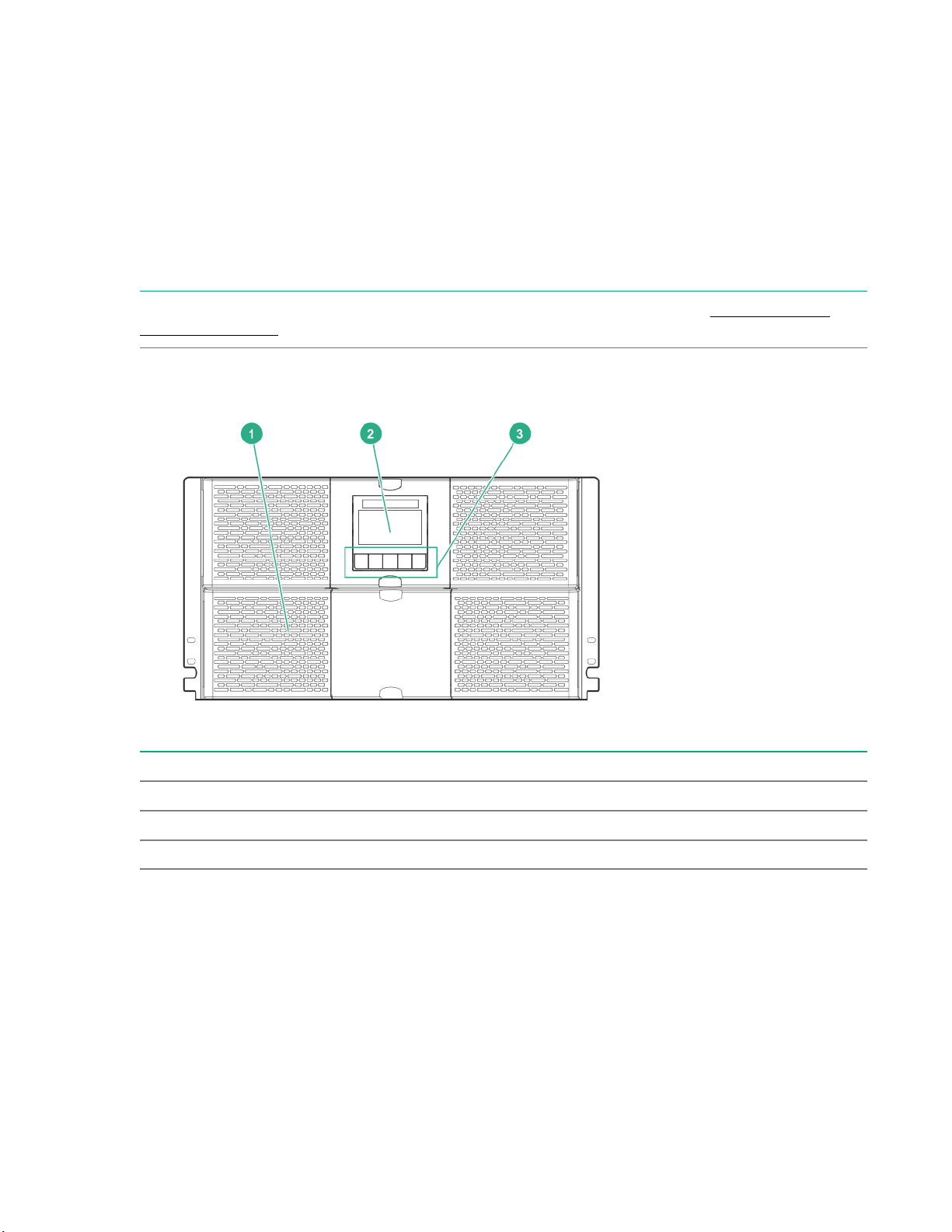
Front panel components
Item Description
1 Battery compartment
2 LED display
3 Control buttons
Component identification 5
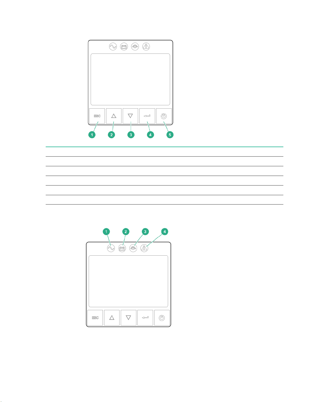
UPS front panel controls
Item Description
1 Escape button
2 Up button
3 Down button
4 Enter button
5 Power button
Front panel LEDs
6 Component identification
Item Indicator Status Description
1 Online mode On The UPS is operating normally online or in high
2 Battery mode On The UPS is on battery mode.
3 Bypass mode On The UPS is in bypass mode.
4 Fault On The UPS has an active alarm or fault. For more
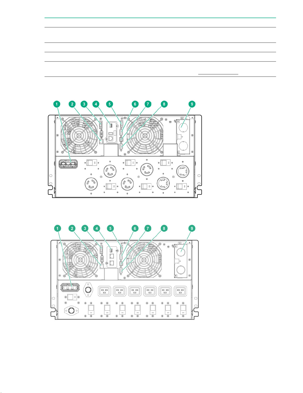
Rear panel components
efficiency mode.
information, see the Troubleshooting section.
Figure 1: G2 R8000 NA/JPN model
Figure 2: G2 R8000 INTL model
Component identification 7

Item Description
1 ERM to UPS connection
2 ERM recognition port
3 Remote Power Off (RPO) terminal block
4 1Gb UPS Network Management Module
5 Remote On/Off (ROO) terminal block
6 Dry contacts communications port
7 USB communications port
NOTE: This port is used for UPS firmware updates. For more information, see USB
communications port.
8 Serial communications port
9 Power I/O interface
ERM rear panel components
Item Description
1 ERM to UPS connector
2 ERM recognition port
USB communications port
NOTE: This port is only used for firmware upgrades. To update the UPS firmware, see the Hewlett
Packard Enterprise website.
8 Component identification
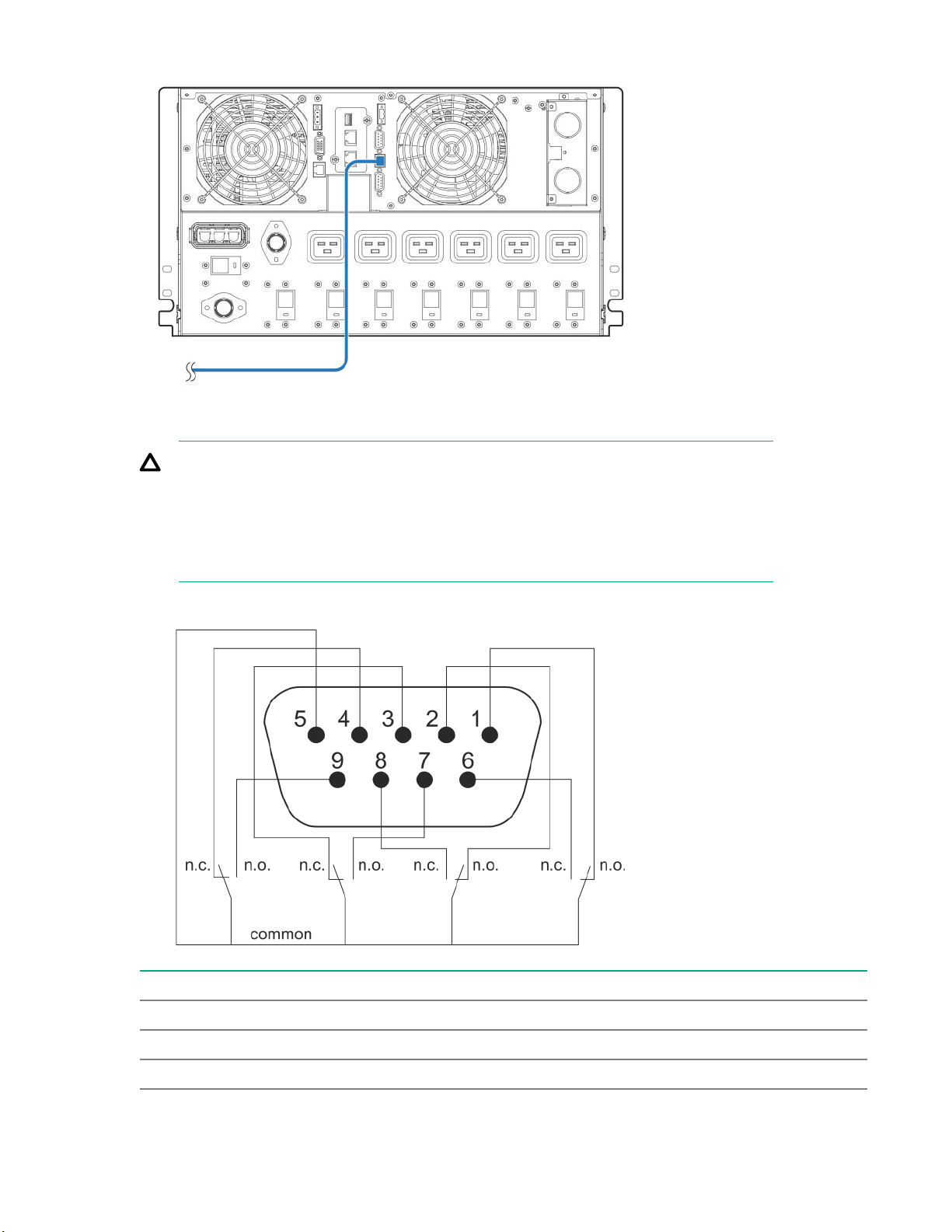
Dry contact port
CAUTION: Before using the dry contact port, the following cautions must be observed:
• The relay output contacts cannot be connected to any utility circuits.
• Reinforced insulation to the utility is required.
• The relay output contacts have a maximum rating of 250VAC/5A.
The UPS has four relay outputs. Each relay output is available with either an open or closed contact.
Pin Description
1 Not on bypass
2 Load not protected
3 Not low battery
Table Continued
Component identification 9
ROO
Pin Description
4 Not on battery
5 User common
6 On bypass
7 Low battery
8 Load protected
9 On battery
n.o. Contact normally open
n.o. Contact normally closed
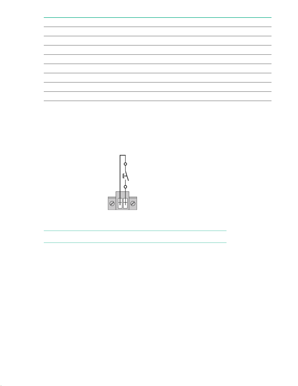
ROO allows remote action of the power button to switch the UPS on and off.
• When the contact changes from open to closed, the UPS is switched-on (or stays On).
• When the contact changes from closed to open, the UPS is powered off (or stays Off).
Figure 3: This figure displays a normally open contact.
NOTE: The on/off control using the power button has priority over the remote control.
RPO port
RPO is used to shut down the UPS remotely. This feature is primarily used for remotely powering down
the UPS if there is an emergency. When RPO is activated, the UPS shuts down the output and all its
power converters immediately. The UPS remains on to alarm the fault.
The RPO circuit is an IEC 60950 safety extra low voltage (SELV) circuit. This circuit must be separated
from any hazardous voltage circuits by reinforced insulation. The RPO must also meet the following
requirements:
• The RPO cannot be connected to any utility connected circuits. Reinforced insulation to the utility is
required. The RPO switch must have a minimum rating of 27 Vdc and 20 mA and be a dedicated
latching-type switch not tied into any other circuit. The RPO signal must remain active for at least 250
ms for proper operation.
• To ensure that the UPS stops supplying power to the load during any mode of operation, the input
power must be disconnected from the UPS when the RPO function is activated.
10 Component identification
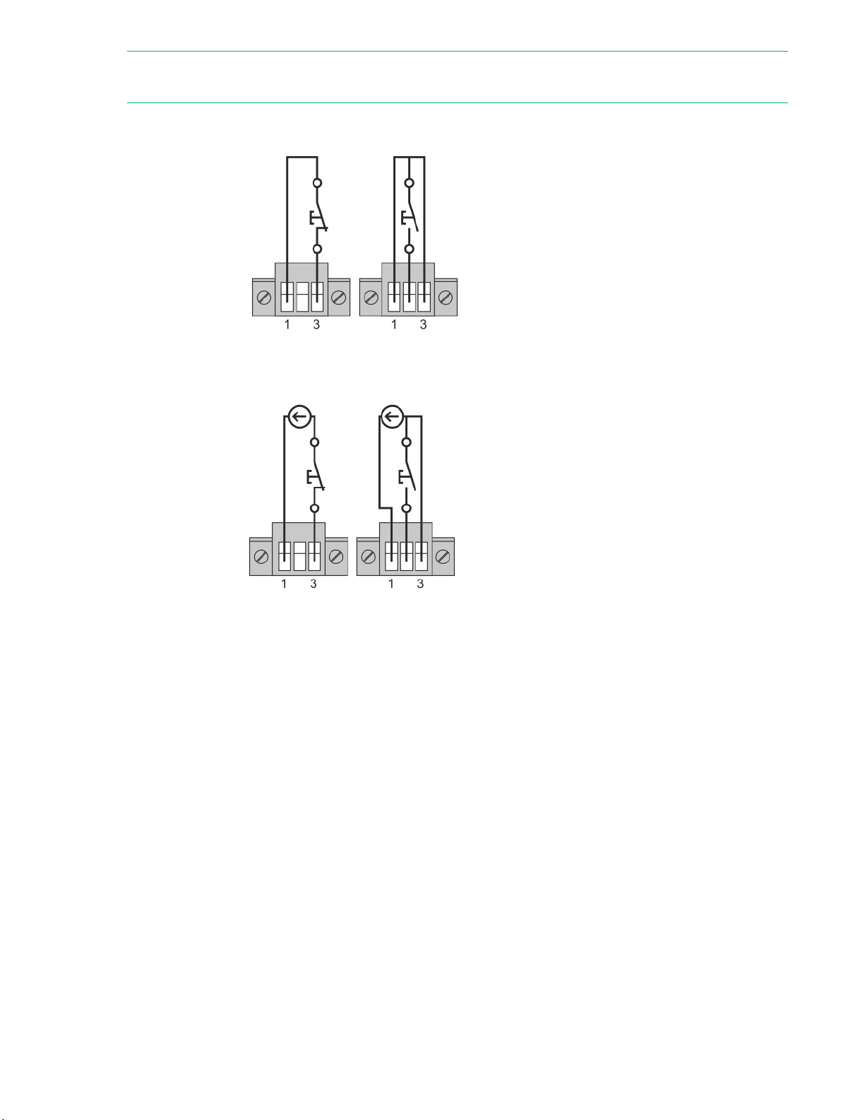
NOTE: Leave the RPO connector installed in the RPO port on the UPS even if the RPO function is not
needed.
The following images illustrate the RPO connections.
Figure 4: Internal power supply
Figure 5: External power supply
Component identification 11

Installation
Precautions
Save these instructions. This document contains important safety instructions that must be followed
during installation, operation, and maintenance of the UPS and batteries.
WARNING: A risk of personal injury from electric shock and hazardous energy levels exists. The
installation of options and routine maintenance and service of this product must be performed by
individuals who are knowledgeable about the procedures, precautions, and hazards associated with
AC power products.
85 187
65 143
This symbol indicates that the UPS exceeds the recommended weight for one
individual to handle safely.
This symbol indicates that the ERM exceeds the recommended weight for one
individual to handle safely.
WARNING: To reduce the risk of personal injury or damage to the equipment, observe local
occupational health and safety requirements and guidelines for manual material handling.
WARNING: To prevent personal injury from earth conductor leakage current:
• Do not operate the UPS while disconnected from the utility power source.
• Disconnect load devices before disconnecting the UPS from the utility power source.
Preparing to install the hardware
Before installing the hardware:
1. Be sure the necessary tools and materials are available.
2. Select an installation site.
3. Prepare the equipment for installation in the rack.
Tools and materials
The following tools are required for installation:
Phillips screwdriver
The following items are supplied with the UPS:
12 Installation

• Screws
• Washers
Selecting a site
WARNING: To prevent fire or electric shock, install the unit in a temperature- and humidity-
controlled indoor environment, free of conductive contaminants.
When selecting a site, consider the following factors:
• Elevated operating ambient temperature—If the equipment is installed in a closed or multiunit rack
assembly, the operating ambient temperature of the rack environment might be greater than room
ambient temperature. Install the equipment in an environment compatible with the operating
temperature. For more information, see Environmental specifications.
• Reduced air flow—In the rack, the rate of air flow required for safe operation of the equipment must
not be compromised.
• Circuit overloading—Consideration must be given to the connection of the equipment to the supply
circuit and the effect that overloading of the circuits might have on overcurrent protection and supply
wiring. Appropriate consideration of equipment nameplate ratings must be used when addressing this
concern.
• Reliable earthing—Reliable earthing of rack-mounted equipment must be maintained. Particular
attention must be given to supply connections other than direct connections to the branch circuit, such
as the use of power strips.
• Electrical requirements—All models require a dedicated (unshared) branch circuit, suitably rated for
the specific UPS as stated in the
Preparing the equipment
Procedure
1. Check the battery recharge date specified on the label that is affixed to the shipping carton.
IMPORTANT: Do not use the battery if the recharge date has passed. If the date on the battery
recharge date label has passed without the battery being recharged, contact an HPE authorized
service representative for directions.
2. Transport the packaged unit to its installation location.
3. Unpack the equipment near the rack where the unit will be assembled.
CAUTION: Always plan the rack installation so that the heaviest item is on the bottom of the
rack. Install the heaviest item first, and continue to populate the rack from the bottom to the top.
UPS input specifications.
Installation 13
 Loading...