

Hewlett Packard Enterprise HPE G2 User Manual

Technical white paper
HPE G2 Racks best practices

Technical white paper
Contents
Introduction ................................................................................................................................................................................................................................................................................................................................................... 3
HPE G2 Rack design ............................................................................................................................................................................................................................................................................................................................. 3
Safety and security ........................................................................................................................................................................................................................................................................................................................... 3
User experience .................................................................................................................................................................................................................................................................................................................................. 3
Power and cooling efficiency .................................................................................................................................................................................................................................................................................................. 3
Datacenter optimization .............................................................................................................................................................................................................................................................................................................. 3
Interoperability ..................................................................................................................................................................................................................................................................................................................................... 4
HPE G2 Rack overview ....................................................................................................................................................................................................................................................................................................................... 4
Certification and regulatory compliance ............................................................................................................................................................................................................................................................................. 5
Waste Electrical and Electronic Equipment directive ............................................................................................................................................................................................................................................. 5
Integration services and software ............................................................................................................................................................................................................................................................................................. 6
HPE Factory Express ..................................................................................................................................................................................................................................................................................................................... 6
HPE Infrastructure Architect................................................................................................................................................................................................................................................................................................... 6
HPE Power Advisor ......................................................................................................................................................................................................................................................................................................................... 6
Rack deployment considerations .............................................................................................................................................................................................................................................................................................. 6
Levels of rack security................................................................................................................................................................................................................................................................................................................... 6
Stabilization requirements ........................................................................................................................................................................................................................................................................................................ 7
Space and cable management requirements .......................................................................................................................................................................................................................................................... 9
Thermal requirements .............................................................................................................................................................................................................................................................................................................. 10
Rack assembly guidelines ...................................................................................................................................................................................................................................................................................................... 10
Installation and maintenance precautions .............................................................................................................................................................................................................................................................. 11
Rack-mountable products ..................................................................................................................................................................................................................................................................................................... 11
Installation planning and considerations ........................................................................................................................................................................................................................................................................ 12
Environmental considerations ........................................................................................................................................................................................................................................................................................... 12
Third-party thermal considerations .............................................................................................................................................................................................................................................................................. 13
Power considerations................................................................................................................................................................................................................................................................................................................. 13
Compatibility ...................................................................................................................................................................................................................................................................................................................................... 14
Grounding and earth leakage current ........................................................................................................................................................................................................................................................................ 14
Equipment clearance and floor loading ........................................................................................................................................................................................................................................................................... 15
Rack and accessory footprints .......................................................................................................................................................................................................................................................................................... 16
Front door clearance .................................................................................................................................................................................................................................................................................................................. 17
Qualified shipping ................................................................................................................................................................................................................................................................................................................................ 18
Qualification of rack components for shipping ................................................................................................................................................................................................................................................... 18
Rack shipping enclosures....................................................................................................................................................................................................................................................................................................... 18
Packing materials and shipping requirements .......................................................................................................................................................................................................................................................... 19
Preparation for shipment ....................................................................................................................................................................................................................................................................................................... 20
Site preparation for receiving integrated racks .................................................................................................................................................................................................................................................. 20

Technical white paper
General considerations ............................................................................................................................................................................................................................................................................................................. 21
Special shipping considerations ....................................................................................................................................................................................................................................................................................... 22
Door height clearances ............................................................................................................................................................................................................................................................................................................ 22
Modes of shipment ...................................................................................................................................................................................................................................................................................................................... 23
Airfreight................................................................................................................................................................................................................................................................................................................................................ 23
Mode of receiving and delivery ........................................................................................................................................................................................................................................................................................ 25
HPE Infrastructure Rack packing and shock pallet assembly .............................................................................................................................................................................................................. 25
Dismounting an Infrastructure Rack from a shock pallet .......................................................................................................................................................................................................................... 33
Installation service ............................................................................................................................................................................................................................................................................................................................... 33
Spares kits ............................................................................................................................................................................................................................................................................................................................................ 33
Additional tools and equipment....................................................................................................................................................................................................................................................................................... 33
HPE Rack warranty ............................................................................................................................................................................................................................................................................................................................ 34
Conclusion .................................................................................................................................................................................................................................................................................................................................................. 34
Appendix A: Glossary ....................................................................................................................................................................................................................................................................................................................... 35
Appendix B: Torque values ......................................................................................................................................................................................................................................................................................................... 36
Resources .................................................................................................................................................................................................................................................................................................................................................... 38

Technical white paper Page 3
Introduction
The initial Hewlett Packard Enterprise (HPE) G2 Rack product introduction includes HPE G2 Advanced Racks, announcement of the next
generation of HPE Standard Series G2 Basic Power Distribution Units (PDUs), and the HPE Infrastructure Architect application to help you
identify the best HPE Rack and Power Infrastructure products for your data center configuration. HPE G2 Advanced Series Racks will continue to
use pre-existing rack accessories with the exception of several new accessory kits including: side panels, grounding kit, baying kit, stabilization kit,
and roof-mount fan kits.
HPE G2 Racks redefines intelligent infrastructure design for the mid-size business and provides a better foundation for the IT of the future. An
intelligent datacenter does more for your business in less time and for less money. HPE has reimagined intelligent infrastructure design from the
ground up and identified five business challenges that present opportunities for improved infrastructure to drive better business practices:
• Safety and security
• User experience
• Power and cooling efficiency
• Datacenter optimization
• Interoperability
HPE G2 Rack design
The HPE G2 Rack product family was designed to address these business challenges in the following ways:
Safety and security
HPE G2 Rack and Power infrastructure is positioned to address existing and evolving security threats. Provisions for third-party locking solutions
(biometric, electronic, and keyed) keep your servers where they belong (you can read more about these capabilities in the “
security” section). HPE also offers locking IEC power cords that lock to, both, the power distribution unit (HPE G2 units only) and to the target
device (server, storage, or networking hardware) regardless of make or model.
User experience
The HPE user experience is assured through the available tools that provide information to guide your choices and the strength of HPE Rack
and Power infrastructure to provide you with unmatched performance and reliability. The HPE Infrastructure Architect application (found at
hpe.com/info/rackandpower
you plan how much power you’ll use month-to-month based on your planned or existing infrastructure. Toolless installation, low-profile PDUs,
and improved cable management provisions get your new infrastructure up and running faster, whether it’s out-of-the-box or finding and fixing a
problem during mid-lifecycle. If you’d prefer to purchase everything assembled and ready to go, our Factory Express option builds the industry’s
best datacenter solutions on the industry’s best racks, and ships it directly to your door.
) guides you to the right products based on your workload, budget, and location. And then HPE Power Advisor helps
Power and cooling efficiency
Power costs are the number one operating expense for most IT infrastructures. And of course, the more power servers consume, the hotter they
get. HPE PDUs can safely operate in ASHRAE A1 – A4 environments up to 60 degrees Centigrade (that’s 10 degrees above industry standard),
and 80% front-door open perforation on our racks (16% higher than the industry leader) allows for greater airflow that helps to minimize cooling
costs.
Levels of rack
Datacenter optimization
Datacenter space is often at a premium, and less room spent on infrastructure means more room for compute. HPE G2 Rack infrastructure is
Intelligent, efficient datacenter infrastructure that deploys faster and in less space than existing infrastructures, leaving more room for compute
and boosting your servers, storage, and networking capabilities.
HPE G2 Rack infrastructure is taller and wider with deeper racks, while maintaining the same, industry-leading durability guaranteed with a 10year warranty. HPE PDUs have been redesigned and utilize toolless installation with more outlets per rack U than any competitor.
Technical white paper Page 4
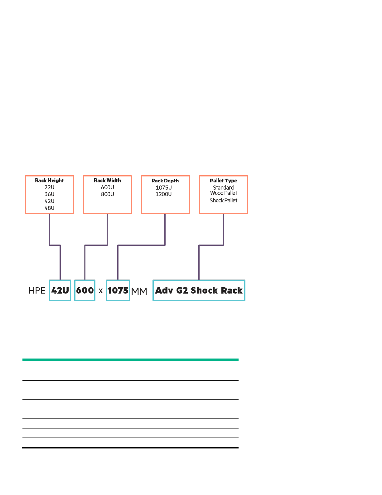
Table 1. HPE G2 Advanced rack sizes and transport configuration
RACK
HPE 22U 600mmx1075mm
HPE 22U 600mmx1075mm G2 Advanced Kitted
HPE 36U 600mmx1075mm G2 Advanced Kitted
HPE 36U 600mmx1075mm
HPE 42U 600mmx1075mm
HPE 42U 600mmx1075mm G2 Advanced Kitted
HPE 42U 600mmx1200mm G2 Advanced Kitted
HPE 42U 600mmx1200mm
HPE 48U 600mmx1075m
Interoperability
Datacenter infrastructure isn’t always purchased at once, isn’t always purchased from the same vendor, and isn’t always designed to work
together with other IT and infrastructure hardware. HPE testing for interoperability and conforming to industry standards is key to effective
product development, and to eliminating problems in purchase, deployment, operation, and maintenance.
While HPE Rack and Power infrastructure utilized to the best advantage as the foundation of an HPE homogeneous datacenter, HPE
understands that most datacenters are heterogeneous. With that in mind, HPE Rack and Power products are built to match EIA-310 industrystandard specification.
HPE’s industry-leading datacenter solutions start with HPE Rack and Power Infrastructure. Our Rack and Power Infrastructure portfolio of
products is designed for HPE servers, storage, and networking – better together and working to drive your business further.
HPE G2 Rack overview
This document outlines recommended practices for configuring, installing, transporting, and establishing a work environment for HPE G2 Racks,
HPE G2 rack transport descriptions include the information shown in Figure 1.
Figure 1. Rack transport configurations
Rack transport configurations for HPE 22U, 36U, 42U, and 48U G2 Advanced Racks include the pallet types listed in Table 1.
KIT TRANSPORT CONFIGURATIONS* PART # PALLET TYPE
G2 Advanced Kitted
G2 Advanced Kitted
G2 Advanced Kitted
G2 Advanced Kitted
m G2 Advanced Kitted
P9K03A Pallet Rack
P9K04A Shock Rack
P9K05A Pallet Rack
P9K06A Shock Rack
P9K07A Pallet Rack
P9K08A Shock Rack
P9K09A Pallet Rack
P9K10A Shock Rack
P9K19A Pallet Rack
* All kits include Side Panels and Baying

Technical white paper Page 5
For complete specifications and product listings of the HPE G2 Advanced Series Racks, refer to the following links:
• HPE G2 Advanced Series Rack QuickSpecs
• HPE Racks for Server, Storage, and Networking family datasheet
• HPE G2 Advanced Series Rack documents and tools
For a complete list of HPE rack options and accessories, go to the main rack page at hpe.com/us/en/integrated-systems/rack-power-cooling.html
For a list of ProLiant servers and options, go to hpe.com/info/proliant
For a complete list of HPE server storage equipment, go to hpe.com/info/serverstorage
Note
See the Resources section at the end of this document for a more complete listing of HPE G2 Advanced Series rack resources.
Certification and regulatory compliance
HPE G2 Advanced Series Racks, while UL qualified, are defined as nonfunctional mechanical storage bays and, therefore, are not certified as
electrical products. The rack does not serve as an overall safety or EMI-rated enclosure, nor does it carry any other agency compliant rating.
However, any product intended for use in an HPE rack should be individually certified as a standalone product. For example, HPE Power
Distribution products, such as uninterruptible power supplies (UPSs) and power distribution units (PDUs) are fully certified as standalone
products.
Certain third-party products may not be fully certified as standalone products. Any product that does not meet standalone certification is not
included in any HPE-specified rack configuration and should not be installed in an HPE rack.
HPE General Specification for Environment (GSE) specifications prohibit or restrict the use of certain chemical compounds in products or in the
manufacture of products. HPE complies with the GSE specifications and restricts the use of these compounds in the development or
manufacture of any HPE product (including third-party supplier product).
The Infrastructure Racks are designed to comply with the applicable safety requirements for Information Technology Equipment (ITE) when the
rack is configured with properly certified equipment. HPE Infrastructure Racks are considered ITE compliant when the following conditions are
met:
• The rack is populated with individually certified products.
• All installation guidelines and instructions are followed.
Waste Electrical and Electronic Equipment directive
The directive on Waste Electrical and Electronic Equipment (WEEE) requires manufacturers to finance the take back and recovery of waste from
electrical and electronic equipment at the end of its useful life.
Any product or product packaging marked with the symbol in figure 2 must not be disposed of with other household waste. The user must
dispose of the product by delivering it to a designated collection point for the recycling of waste electrical and electronic equipment. For more
information about locations to drop off equipment for recycling, contact a local city office, the household waste disposal service, or the business
where the product was purchased.

Technical white paper Page 6
Several resources are available for planning rack configurations. Those resources include HPE Factory Express, HPE Infrastructure
Architect, HPE Power Advisor, and HPE rack documentation.
Figure 2. Waste Electrical symbol
Integration services and software
HPE Factory Express
Factory Express is a robust portfolio of flexible, pre-priced, configured, customized, and integrated factory solutions and deployment services
supporting HPE products from the desktop to the data center with Windows®, Linux®, and HP-UX.
For specific information, see the HPE Factory Express link: hpe.com/info/factoryexpress
In addition to this available integration option, HPE also provides information links and contacts for questions regarding rack and product
compatibility. Go to hpe.com/us/en/integrated-systems/rack-power-cooling.html
for more information.
HPE Infrastructure Architect
You can use HPE Infrastructure Architect to build a custom infrastructure solution. This tool is for salespeople, channel partners, and experienced
IT buyers. It’s a simple mix-and-match application that ensures the infrastructure you buy will work with the servers, storage, networking, and
power supply infrastructure you already have. And when completed, the tool will also connect you to an HPE salesperson that can have your
solution shipped to you. You can find the HPE Infrastructure Architect at iallb.itcs.hpe.com/
.
HPE Power Advisor
HPE Power Advisor is an easy-to-use tool that estimates your data center power requirements for your server and storage configurations.
Version 6.x includes the new HPE ProLiant Gen 9 servers and options as well as a new Smart Update feature that automatically updates your
application when opened.
Rack deployment considerations
The following sections describe the HPE components and options available for the HPE G2 Racks that are available to achieve safety, regulatory
compliance, or functionality requirements.
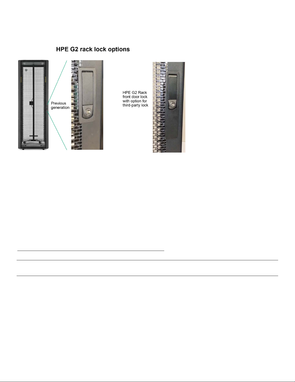
Levels of rack security
Either of the following conditions may be necessary to comply with certain safety certifications:
• Racks must be located in a restricted access area that is only accessible to trained personnel.
• Racks must be configured with lockable hardware.
HPE rack front doors, rear doors, and side panels support this locking requirement. Rear split doors are standard. HPE G2 Racks also include new
tooling that allows you to easily remove the default lock and replace with a third-party lock (See Figure 3).
Technical white paper Page 7
Figure 3. Third-party locking options
HPE Infrastructure Rack front doors
All HPE G2 Rack models ship with front doors. The 600mm wide 36U, 42U, and 48U front doors (and necessary hardware) are backwards
compatible with the G1 Series Racks of the same width and height; this enables customers to have all 600mm wide racks standardized with the
same updated look, if desired.
HPE Infrastructure Rack rear doors
All HPE G2 Rack models ship with rear doors as part of the standard configuration. The Infrastructure Rack rear door has been upgraded to
provide additional open space for exhaust air.
HPE Side Panel Option Kit
Side panels aid in providing proper front-to-rear airflow and a first level of security. Side Panel Option Kits are available for all rack models.
Rack options installation instructions can be found in the HPE Rack Options Installation Guide at:
hpe.com/hpsc/doc/public/display?docId=emr_na-c03209378&lang=en-us&cc=us
Note
All G2 Advanced Series Racks ship with side panels; however, side panels are also available as option kits.
Stabilization requirements
Rack stability is of special concern when equipment is routinely installed, removed, or accessed within the rack. Stability is addressed with a
combination of leveling feet, baying kits, fixed stabilizers, and ballast.
Leveling feet
Leveling feet ship installed in each rack. It allows stabilization and levels the racks at the installation site. HPE Infrastructure Rack hardware kits
also include leveling pads that are used with the feet during rack stabilization.
HPE Baying Kit
Baying kits are used to physically connect adjacent racks to create a row of two or more units. Racks that are bayed together with a baying kit are
more stable and reduce the potential of the rack to tip. G2 Advanced Series Racks ship with baying kits that allow for baying with side panels

Technical white paper Page 8
installed. The same baying kit will support the 10000 G2, Advanced, and G2 Advanced Racks. This baying kit is used to connect racks of the
same depth.
HPE Offset Baying Kit
Offset baying kits are used to connect adjacent racks that are of a different depth. Kits are available that support the connection of 1075mm
deep racks to both 1200mm racks and older 1000mm deep racks.
HPE Stabilizer Kit
Fixed stabilizers are anti-tip feet (front and side) that provide stability and support when equipment is installed, removed, or accessed within the
rack. Both HPE 600mm stabilizers and HPE Heavy Duty 600mm stabilizers are available. For single racks or bays of three racks, with rackmountable components, on extendable rails, that are less than 100 kg (220 lb.), a standard 600mm stabilizer is required.
If racks are secured together with baying kits, the side feet installed on each end of the row of racks are considered optional. Rack rows with four
or more bayed racks do not need a stabilizer kit installed.
HPE recommends using stabilizer option kits when one or more of the following situations occur:
If a standard 600mm (23.62 in) front stabilizing foot is installed on a standalone rack, the side feet, provided with the fixed stabilizer kit, should
also be installed to stabilize standalone racks from the side.
• A heavy-duty 600mm (23.62 in) front stabilizer foot is required in either of the following situations:
– A single rack-mountable component, on extendable rails, weighing 100 kg (220 lb.) or greater is installed in a standalone rack.
– A rack row of three or fewer racks are bayed together
• To reduce the risk of personal injury or damage to the equipment, be sure that:
– The leveling feet are extended to the floor
– The full weight of the rack rests on the leveling feet
– The stabilizing feet are attached to the rack if it is a single-rack installation
– The racks are coupled together in multiple-rack installations
– Only one component is extended at a time or the rack may become unstable
HPE Ballast Option Kit
Ballast plates add weight to a rack and improve side-to-side and front-to-back mechanical stability for standalone racks or a row of three or fewer
racks bayed together. Ballast plates fit in the zero-U space at the interior sides of the rack and should be installed into the rack prior to
installation of any other equipment.
When increasing rack weight, it is important to consider that a rack with a light static load (less than 95 kg/210 lb.) should have ballast plates
installed to provide extra weight, thus reducing the possibility of the rack tipping over if a significant force were to be applied to the rear or side
of the rack. Racks with a heavier static load (greater than 95 kg/210 lb.), depending on the particular configuration involved, may not require
ballasts.
Multiple ballast kits may be necessary to provide sufficient weight. Each kit contains two 18 kg (40 lb.) ballast plates. Ballast plates should be
added to the rack until the total weight of components installed into the rack is at least 95 kg (210 lb.).
For example, a lightly loaded rack configured with 23 kg (50 lb.) of equipment requires two ballast kits (four ballast plates). The total weight of
four ballast plates is 72 kg (160 lb.). Therefore, the total installed weight of the rack components would be 95 kg (210 lb.), the minimum
recommended rack installed component weight.
Should any rack component on extendable rails weigh more than 46 kg (100 lb.), there must be an additional 95 kg (210 lb.) of equipment
weight in the rack (excluding the weight of the component) to provide balance and maintain rack stability when the component is extended on
its rails. In this instance, ballast plates should be added until the total rack component weight is 138 kg (300 lb.) or greater.
Total weight of installed equipment along with total weight of ballast plates is equal to total rack component weight.

Technical white paper Page 9
Depending upon the installed components, racks may require both ballast and stabilizer.
Warning
To reduce the risk of personal injury or damage to equipment, extend only one component at a time. The rack may become unstable if more than
one component is extended.
Stabilization for seismic activity
Rack installations in geographical areas where there is a risk of seismic activity may require special considerations for stabilizing the rack. Consult
your local building code or a licensed building engineer.
Important
The Infrastructure Racks are certified to meet International Building Code (IBC) standards in all regions. Within the IBC, the HPE Enterprise Racks
fall within the nonstructural component category, specifically mechanical and electrical components. The equipment is assumed to include
communication equipment, computers, instrumentation, and controls.
Note
Network Equipment Building Systems (NEBS) Zone 4 or Office of Statewide Health Planning and Development (OSHPD) ratings are outside of
standard data center rack compatibility and require a solution-based approach that addresses the rack and all installed components.
A building engineer will need to determine the requirements for which, if any, ballast and stabilizer kits are required. If the rack is bolted to the
floor or to adjacent racks that have sufficient combined weight, additional stabilization products may not be required.
HPE Tie Down Option Kit
The Rack Tie Down Kit provides a means for meeting IBC guidelines to anchor an HPE G2 Rack to the floor in geographical areas prone to
seismic activity. This product provides a solution to aid in avoiding damage or serious injury in the event of building or floor movement.
Space and cable management requirements
The HPE G2Advanced Series Racks include cable management and other options allow you to customize your rack. There is a rear PDU and
Accessory Mounting Bracket to ease cable management and installation of PDUs,
1200mm Deep Racks
Cables and equipment can be damaged in use or in shipping if there is insufficient room in the rack. The 1200mm extended depth rack can be
used when additional room is required at the rear of the rack to provide adequate space for equipment and associated cables.
Cable management kits
Due to the dynamic nature of the rack environment, the cabling of systems has very few hard rules. HPE Cable management kits provide an easy
way to organize and route cables within racks. The HPE Rack Cable Management Kit includes a 1U and 2U front cable entry panel with brush
inserts, 2x crossover cable brackets, 10x D-rings, 10x hook and loop straps 8 inch, 10x hook and loop straps 10 inch, mounting hardware.
Several kits are available as options to assist with cabling requirements.
Additional information on HPE cable management kits is available at hpe.com/info/rackandpower.
are as follows:
• Use the HPE One Config Simple (OCS) available at hpe.com/SimplifiedConfig/Welcome to fully plan the rack and server setup prior to
installation.
• For good visual reference, do not install cabling until all equipment is installed in the rack.
• Avoid dressing cabling tightly over sharp edges of railing or panels.
• Do not pinch cables between components.
HPE general guidelines for cable management

Technical white paper Page 10
Table 2. Rack assembly guidelines
COMPONENT
Weight
Keyboard/video/mouse (KVM) switchbox
Keyboard/integrated keyboard monitor
Monitor
Balance
• Avoid tight-bend radii. Cables should never be bent tight enough to cause a crease in the sheathing. Fiber cables must not violate their
minimum bend radius without exception.
• When securing cables inside the rack, the bundle should be dressed in such a way as to avoid interference with installed components or rack
side panels or rails.
• When possible, use all cable management arms included in component kits.
• For components that must be movable while powered on, ensure a full range of motion is possible without cable interference or disconnect.
Cables dressed on management arms must be secured enough to prevent movement into interference or pinch areas, yet not so tight as to
cause binding to the arm.
• Separate power and signal cables as much as possible. For example, dress all signal cables on the left side of the rack and all power cables on
the right side of the rack.
• Ensure that cabling does not impede the airflow to the rack-mountable servers or increase the internal rack temperature beyond the specified
maximum rating.
A list of available extension kits can be found on the main rack options product page at hpe.com/info/rackandpower
.
Thermal requirements
Equipment that is exposed to excessive heat may not operate correctly and may experience abnormally high failure rates. The Infrastructure
Rack air flows from the front to the rear of the rack. Roof-mounted fan kits may help meet additional thermal requirements of rack-mounted
equipment and are used to keep the ambient temperature inside the rack within the specified operational limits of the equipment.
Rack assembly guidelines
Table 2 lists guidelines to follow when physically placing components in an Infrastructure Rack.
GUIDELINE
Sort all components by weight, placing the heaviest components at the bottom of the rack.
Mount the switchbox either behind the keyboard or within a sidewall cavity to provide a zero-U space
solution.
When using any size rack, install the keyboard/integrated keyboard monitor at a level that is in the
correct ergonomic position where your shoulders and neck are relaxed.
Ergonomic considerations should drive the placement of a monitor in the rack, whether it is a CRT or
flat-panel design. It is recommended to arrange the screen or rack-mountable flat-panel monitor a
minimum of 4Us above the keyboard tray. Most customers prefer to place the video system high in
the rack, especially in a full rack, to allow easier access to other system components below it.
When baying racks to create a row, be sure to distribute the weight load among the racks and place
the heaviest components at the bottom of each rack. For example, if you have several uninterruptible
power supply (UPS) units and several servers, do not put all of the UPS units into one rack—distribute
the weight evenly in the bottom positions of each rack.
For further information regarding component placement, refer to the Important Safety Instructions that are shipped with the rack and with the
“Safety and Comfort Guide”

Technical white paper Page 11
Table 3. Rack assembly guidelines
PRECAUTION
Follow manufacturer instructions
Be aware of power voltages and use trained personnel
Secure
Unless the equipment is installed in a restricted access area, rack equipment should be operated only
Provide overhead clearance for fire sprinkler devices
Installation and maintenance precautions
To reduce the risk of electric shock or damage to the equipment when installing, maintaining, or servicing Enterprise products, observe the
general precautions listed in table 3.
DESCRIPTION
all equipment
Always refer to the individual equipment installation instructions for any special considerations when
installing equipment in a rack.
Some Enterprise products are capable of producing hazardous voltages and hazardous energy levels.
The installation of internal options and routine maintenance and service of these products should be
performed only by individuals who are knowledgeable with the procedures, precautions, and hazards
associated with this type of equipment. Refer to the documentation included with each product to
determine whether it belongs in this category.
with all enclosures in place and properly secured. Always refer to the equipment installation guide and
follow all applicable warnings and precautions.
A minimum clearance is required between the top of the rack and any fire protection sprinkler devices.
Check your local building codes for details.
Moving racks with casters
Racks with casters should be moved with care. Sudden stops, excessive force, and uneven surfaces may cause the product to overturn. HPE G2
Racks have casters that are fixed in the front and swivel in the rear due to stability and safety concerns. Therefore, it is both recommended and
easier to move the rack with the back as the leading edge. For long and straight runs, roll the rack with the front, fixed casters leading. For
maneuverability when moving the rack into a tight spot, it is better to lead with the rear, swiveling the casters. When rolling the rack, make sure to
push firmly on the front doorframe and not the door mesh.
Warning
To reduce the risk of personal injury or damage to the equipment, do not attempt to move large equipment racks alone. Obtain adequate
assistance to stabilize the rack during movement or hire professional equipment riggers.
Caution
To reduce the risk of damage to the casters, make sure that the full weight of the rack rests on the leveling feet (when in position) and not on the
casters. The casters are designed only as an aid in moving the rack into position. They are not designed to support the weight of the rack, and
the casters may become damaged if relied on to support the rack.
Rack-mountable products
Because computer components are stacked vertically in a rack, adhere to the following precautions to facilitate rack stability:
• Use the configuration you prepared with the HPE One Config Simple Tool as a guideline for installing the components.
• Load heavier components first and load the rack from the bottom up.
• When coupling or baying racks, be sure to balance the weight load between or among the racks, placing the heaviest components at the
bottom. For example, if you have several UPS units and several servers, do not put all of the UPS units into one rack—distribute them evenly in
the bottom positions among the racks.
• Allow a minimum clearance of 762mm (30 in) at the back of the rack.
• Allow a minimum of 1219mm (48 in) clearance beyond the front of the rack to permit server installation and removal. This applies to both
individual rack installations as well as when aligning rack rows so that the front doors are facing each other. See figure 4.
• Use caution when pressing the component rail release latches and sliding a component into the rack. The side rails can pinch your fingers and
cables.
 Loading...