

Page 1

A
HPE FlexFabric 5940 Switch Series
CL and QoS Configuration Guide
Part number: 5200-1002b
Software version: Release 25xx
Document version: 6W102-20170830
Page 2

© Copyright 2017 Hewlett Packard Enterprise Development LP
The information contained herein is subject to change without notice. The only warranties for Hewlett Packard
Enterprise products and services are set forth in the express warranty statements acco mpanying such
products and services. Nothing herein should be construe d as constituting an additional warranty. Hewlett
Packard Enterprise shall not be liable for technical or editorial errors or omissions co ntained herein.
Confidential computer software. V alid license from Hewlett Packard Enterprise required for possession, use, or
copying. Consistent with FAR 12.211 and 12.212, Commercial Computer Software, Computer Software
Documentation, and T e chnical Data for Commercial Items are licensed to the U.S. Government under vendor’s
standard commercial license.
Links to third-party websites take you outside the Hewlett Packard Enterprise website. Hewlett Packard
Enterprise has no control over and is not responsible for information outside the Hewlett Packard Enterprise
website.
Acknowledgments
Intel®, Itanium®, Pentium®, Intel Inside®, and the Intel Inside logo are trademarks of Intel Corporation in the
United States and other countries.
Microsoft® and Windows® are either registered trademarks or trademarks of Microsoft Corporation in the
United States and/or other countries.
Adobe® and Acrobat® are trademarks of Adobe Systems In corporated.
Java and Oracle are registered trademarks of Oracle and/or its affiliates.
UNIX® is a registered trademark of The Open Group.
Page 3

Contents
Configuring ACLs ············································································· 1
Overview ·································································································································· 1
ACL types ·························································································································· 1
Numbering and naming ACLs ································································································ 1
Match order ························································································································ 1
Rule numbering ·················································································································· 2
Fragment filtering with ACLs ·································································································· 3
Configuration restrictions and guidelines ························································································· 3
Configuration task list·················································································································· 4
Configuring a basic ACL ·············································································································· 4
Configuring an IPv4 basic ACL ······························································································· 4
Configuring an IPv6 basic ACL ······························································································· 5
Configuring an advanced ACL ······································································································ 6
Configuring an IPv4 advanced ACL ························································································· 6
Configuring an IPv6 advanced ACL ························································································· 7
Configuring a Layer 2 ACL ··········································································································· 8
Configuring a user-defined ACL ···································································································· 9
Copying an ACL ······················································································································ 10
Configuring packet filtering with ACLs ·························································································· 10
Applying an ACL to an interface for packet filtering ··································································· 10
Configuring the applicable scope of packet filtering on a VLAN interface ······································· 11
Configuring logging and SNMP notifications for packet filtering ··················································· 11
Setting the packet filtering default action················································································· 12
Displaying and maintaining ACLs ································································································ 12
ACL configuration examples ······································································································· 13
Interface-based packet filter configuration example ··································································· 13
QoS overview ················································································ 15
QoS service models ················································································································· 15
Best-effort service model ···································································································· 15
IntServ model ··················································································································· 15
DiffServ model ·················································································································· 15
QoS techniques overview ·········································································································· 15
Deploying QoS in a network ································································································ 16
QoS processing flow in a device ··························································································· 16
Configuring a QoS policy ································································· 18
Non-MQC approach ················································································································· 18
MQC approach ························································································································ 18
Configuration procedure diagram ································································································ 18
Defining a traffic class ··············································································································· 19
Defining a traffic behavior ·········································································································· 19
Defining a QoS policy ··············································································································· 19
Applying the QoS policy ············································································································ 20
Applying the QoS policy to an interface ·················································································· 20
Applying the QoS policy to VLANs ························································································ 21
Applying the QoS policy globally ··························································································· 21
Applying the QoS policy to a control plane ·············································································· 21
Applying the QoS policy to a user profile ················································································ 22
Displaying and maintaining QoS policies ······················································································· 23
Configuring priority mapping ····························································· 24
Overview ································································································································ 24
Introduction to priorities ······································································································ 24
Priority maps ···················································································································· 24
Priority mapping configuration tasks ····························································································· 25
Configuring a priority map ·········································································································· 25
i
Page 4

Configuring an interface to trust packet priority for priority mapping ····················································· 26
Changing the port priority of an interface ······················································································· 26
Displaying and maintaining priority mapping ·················································································· 27
Priority mapping configuration examples ······················································································· 27
Port priority configuration example ························································································ 27
Priority mapping table and priority marking configuration example ··············································· 28
Configuring traffic policing, GTS, and rate limit ····································· 32
Overview ································································································································ 32
Traffic evaluation and token buckets ······················································································ 32
Traffic policing ·················································································································· 33
GTS ······························································································································· 34
Rate limit ························································································································· 35
Configuration restrictions and guidelines ······················································································· 36
Configuring traffic policing by using the MQC approach ···································································· 36
Configuring GTS by using the non-MQC approach ·········································································· 37
Configuring the rate limit for an interface ······················································································· 38
Displaying and maintaining traffic policing, GTS, and rate limit ··························································· 38
Traffic policing, GTS, and rate limit configuration example ································································ 38
Network requirements ········································································································ 38
Configuration procedure ····································································································· 39
Configuring congestion management ················································· 42
Overview ································································································································ 42
SP queuing ······················································································································ 42
WRR queuing ··················································································································· 43
WFQ queuing ··················································································································· 44
Configuration approaches and task list ························································································· 44
Configuring per-queue congestion management ············································································· 45
Configuring SP queuing ······································································································ 45
Configuring WRR queuing ··································································································· 45
Configuring WFQ queuing ··································································································· 46
Configuring SP+WRR queuing ····························································································· 46
Configuring SP+WFQ queuing ····························································································· 47
Configuring a queue scheduling profile ························································································· 48
Configuration restrictions and guidelines ················································································ 49
Configuration procedure ····································································································· 49
Queue scheduling profile configuration example ······································································ 50
Displaying and maintaining congestion management ······································································· 51
Configuring congestion avoidance ····················································· 52
Overview ································································································································ 52
Tail drop ·························································································································· 52
RED and WRED ··············································································································· 52
Relationship between WRED and queuing mechanisms ···························································· 53
ECN ······························································································································· 53
Configuring and applying a queue-based WRED table ····································································· 54
Configuration procedure ····································································································· 55
Configuration example ········································································································ 55
Displaying and maintaining WRED ······························································································ 56
Configuring traffic filtering ································································ 57
Configuration procedure ············································································································ 57
Configuration example ·············································································································· 57
Network requirements ········································································································ 57
Configuration procedure ····································································································· 58
Configuring priority marking ······························································ 59
Configuration procedure ············································································································ 59
Configuration example ·············································································································· 60
Network requirements ········································································································ 60
Configuration procedure ····································································································· 61
ii
Page 5

Configuring nesting ········································································· 63
Configuration procedure ············································································································ 63
Configuration example ·············································································································· 63
Network requirements ········································································································ 63
Configuration procedure ····································································································· 64
Configuring traffic redirecting ···························································· 66
Configuration procedure ············································································································ 66
Configuration example ·············································································································· 67
Network requirements ········································································································ 67
Configuration procedure ····································································································· 68
Configuring global CAR ··································································· 69
Overview ································································································································ 69
Aggregate CAR ················································································································· 69
Hierarchical CAR ··············································································································· 69
Configuring aggregate CAR by using the MQC approach ································································· 70
Displaying and maintaining global CAR ························································································ 70
Configuring class-based accounting ··················································· 71
Configuration procedure ············································································································ 71
Configuration example ·············································································································· 72
Network requirements ········································································································ 72
Configuration procedure ····································································································· 72
Appendixes ··················································································· 74
Appendix A Acronym ················································································································ 74
Appendix B Default priority maps ································································································· 74
Appendix C Introduction to packet precedence ··············································································· 75
IP precedence and DSCP values ·························································································· 75
802.1p priority ··················································································································· 77
EXP values ······················································································································ 77
Configuring time ranges ··································································· 79
Configuration procedure ············································································································ 79
Displaying and maintaining time ranges ························································································ 79
Time range configuration example ······························································································· 79
Configuring data buffers ·································································· 81
Configuration task list················································································································ 82
Enabling the Burst feature ·········································································································· 82
Configuring data buffers manually ······························································································· 83
Setting the total shared-area ratio ························································································· 83
Setting the maximum shared-area ratio for a queue ·································································· 83
Setting the fixed-area ratio for a queue··················································································· 83
Applying data buffer configuration ························································································· 84
Displaying and maintaining data buffers ························································································ 84
Burst configuration example ······································································································· 84
Configuring QCN ············································································ 86
Basic concepts ························································································································ 86
QCN message format ··············································································································· 86
Data flow format ················································································································ 86
CNM format ····················································································································· 87
How QCN works ······················································································································ 88
QCN algorithm ························································································································ 89
CP algorithm ···················································································································· 89
RP algorithm ···················································································································· 89
CND ······································································································································ 90
CND defense mode ··········································································································· 90
Priority mapping ················································································································ 90
iii
Page 6

Protocols and standards ············································································································ 90
QCN configuration task list ········································································································· 90
Enabling QCN ························································································································· 91
Configuration prerequisites ·································································································· 91
Configuration procedure ····································································································· 91
Configuring CND settings ·········································································································· 91
Configuring global CND settings ··························································································· 91
Configuring CND settings for an interface ··············································································· 92
Configuring congestion detection parameters ················································································· 92
Displaying and maintaining QCN ································································································· 93
QCN configuration examples ······································································································ 93
Basic QCN configuration example ························································································· 93
MultiCND QCN configuration example ··················································································· 96
Document conventions and icons ···················································· 102
Conventions ························································································································· 102
Network topology icons ··········································································································· 103
Support and other resources ·························································· 104
Accessing Hewlett Packard Enterprise Support ············································································ 104
Accessing updates ················································································································· 104
Websites ······················································································································· 105
Customer self repair ········································································································· 105
Remote support ·············································································································· 105
Documentation feedback ·································································································· 105
Index ························································································· 107
iv
Page 7
Configuring ACLs
Overview
An access control list (ACL) is a set of rules for identifying traffic based on criteria such as source IP
address, destination IP address, and port number. The rules are also called permit or deny
statements.
ACLs are primarily used for packet filtering. "Configuring packet filtering with ACLs" p
example. You can use ACLs in QoS, security, routing, and other modules for identifying traffic. The
packet drop or forwarding decisions depend on the modules that use ACLs.
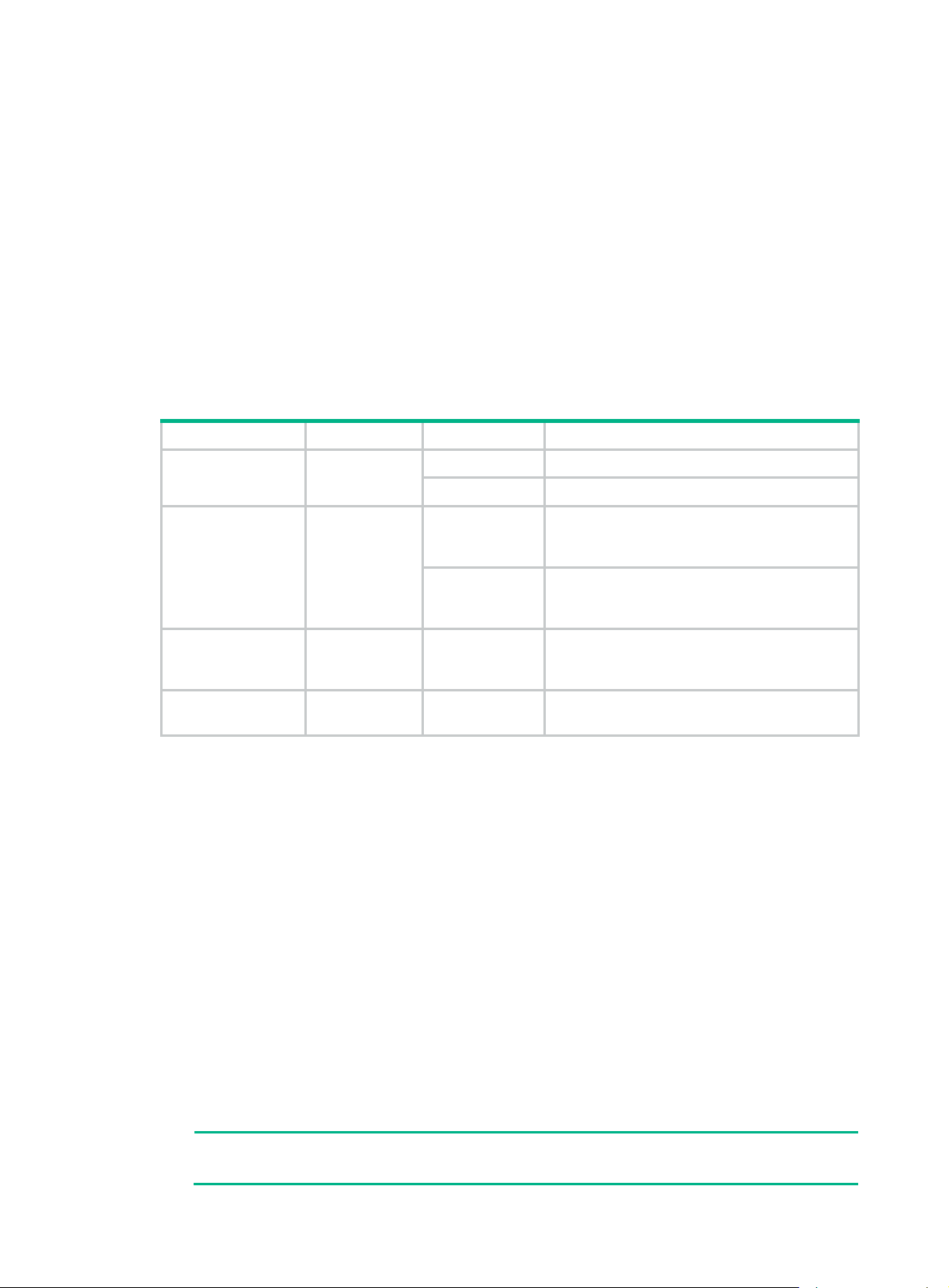
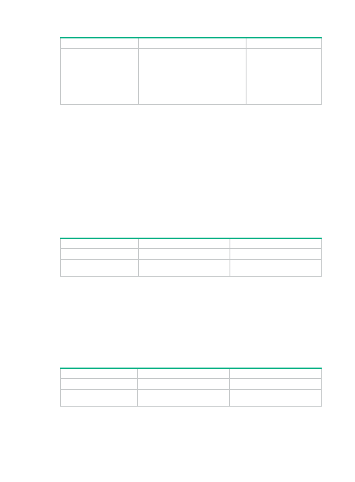
ACL types
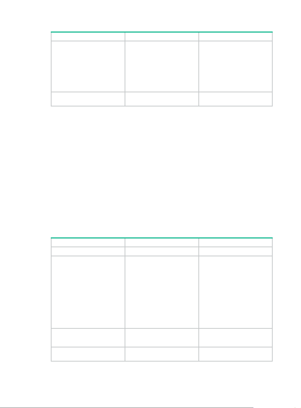
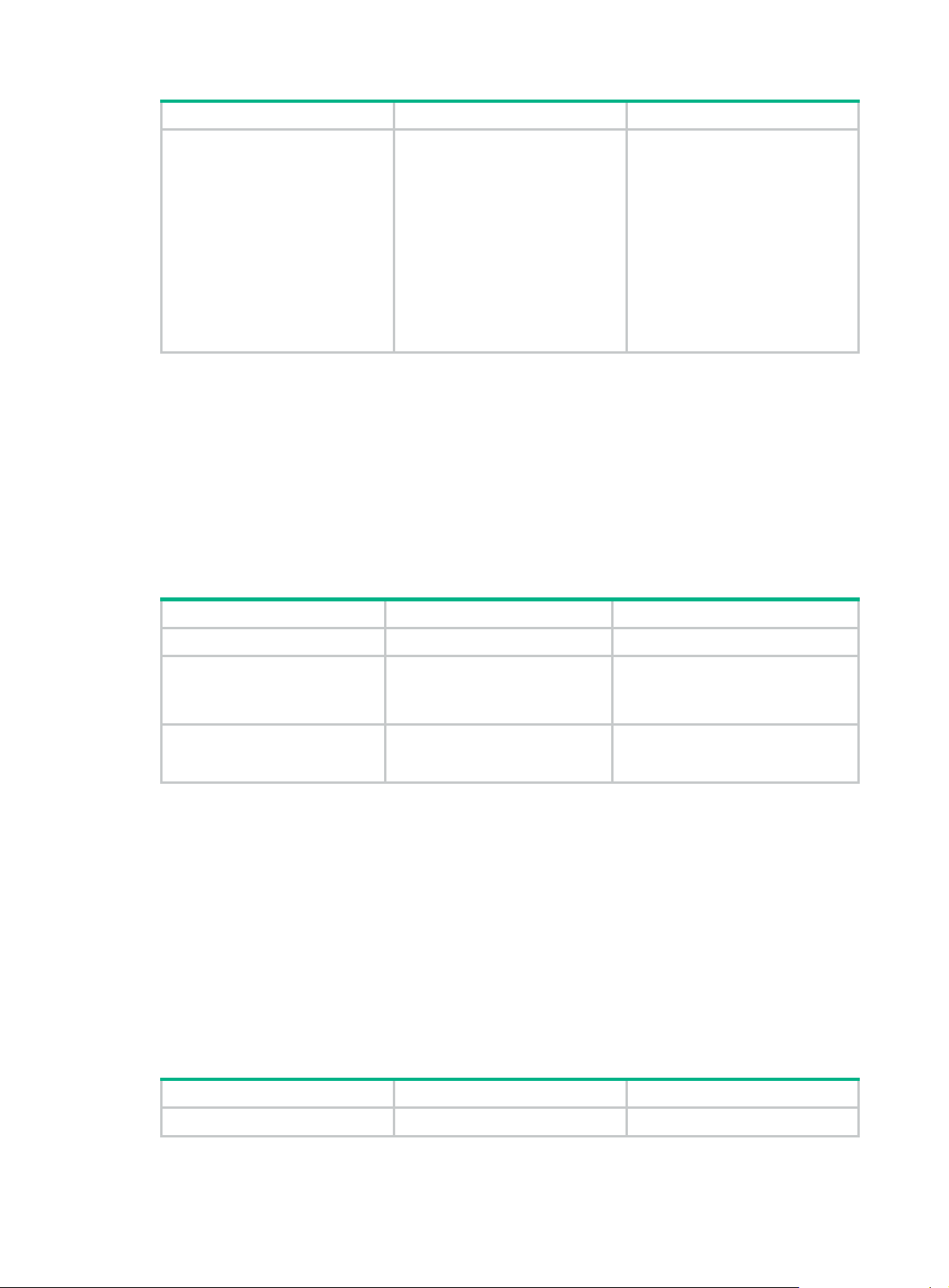
Type ACL number IP version Match criteria
Basic ACLs 2000 to 2999
Advanced ACLs 3000 to 3999
Layer 2 ACLs 4000 to 4999 IPv4 and IPv6
User-defined ACLs 5000 to 5999 IPv4 and IPv6
IPv4
IPv6 Source IPv6 address.
IPv4
IPv6
Source IPv4 address.
Source IPv4 address, destination IPv4
address, packet priority, protocol number, and
other Layer 3 and Layer 4 header fields.
Source IPv6 address, destination IPv6
address, packet priority, protocol number, and
other Layer 3 and Layer 4 header fields.
Layer 2 header fields, such as source and
destination MAC addresses, 802.1p priority,
and link layer protocol type.
User specified matching patterns in protocol
headers.
rovides an
Numbering and naming ACLs
When creating an ACL, you must assign it a number or name for identification. You can specify an
existing ACL by its number or name. Each ACL type has a unique range of ACL numbers.
For an IPv4 basic or advanced ACL, its ACL number or name must be unique in IPv4. For an IPv6
basic or advanced ACL, its ACL number and name must be unique in IPv6. For an ACL of some
other type, its number or name must be globally unique.
Match order
The rules in an ACL are sorted in a specific order. When a packet matches a rule, the device stops
the match process and performs the action defined in the rule. If an ACL contains overlapping or
conflicting rules, the matching result and action to take depend on the rule order.
The following ACL match orders are available:
• config—Sorts ACL rules in ascending order of rule ID. A rule with a lower ID is matched before
a rule with a higher ID. If you use this method, check the rules and their order carefully.
NOTE:
The match order of user-defined ACLs can only be config.
1
Page 8
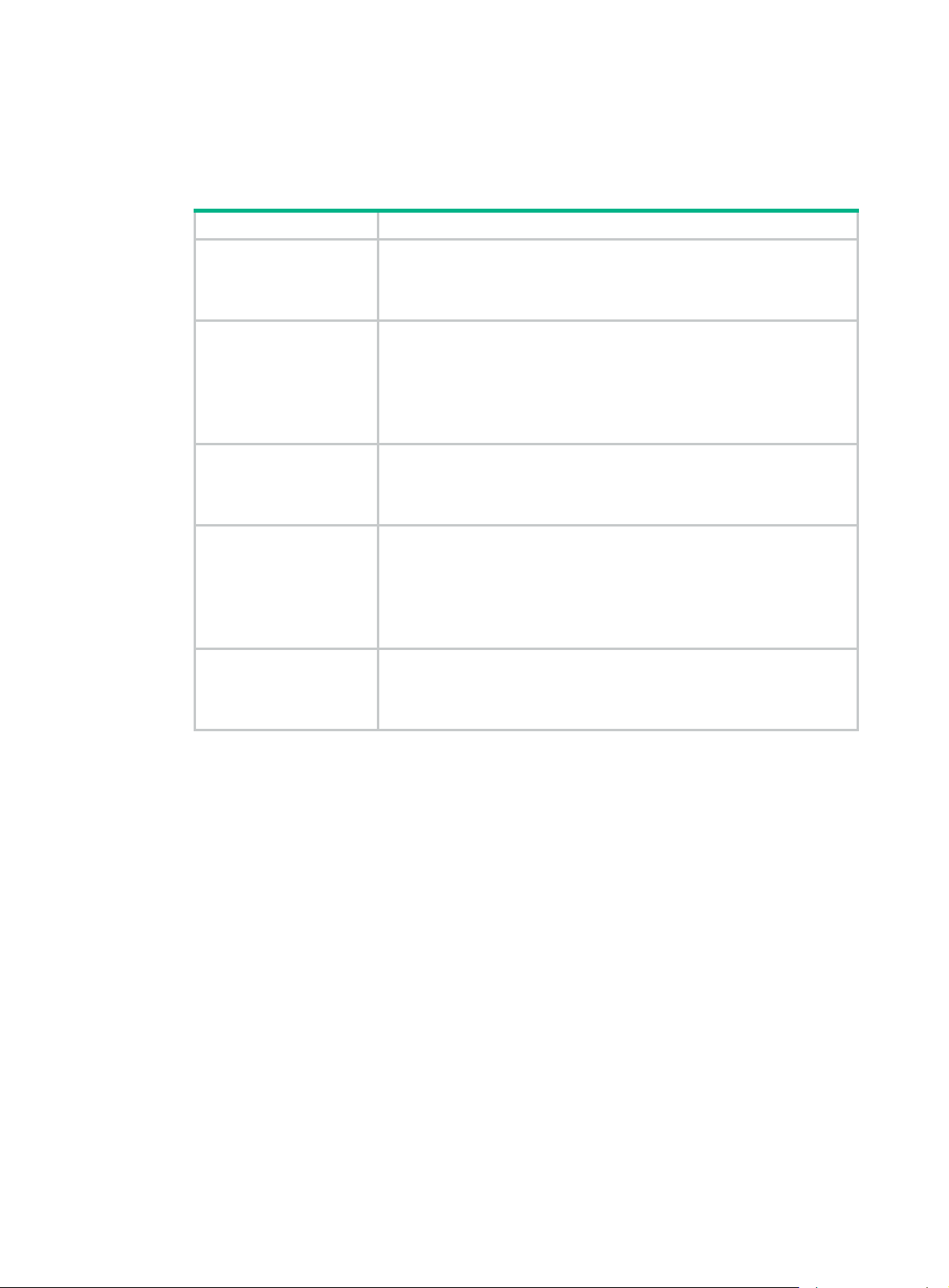
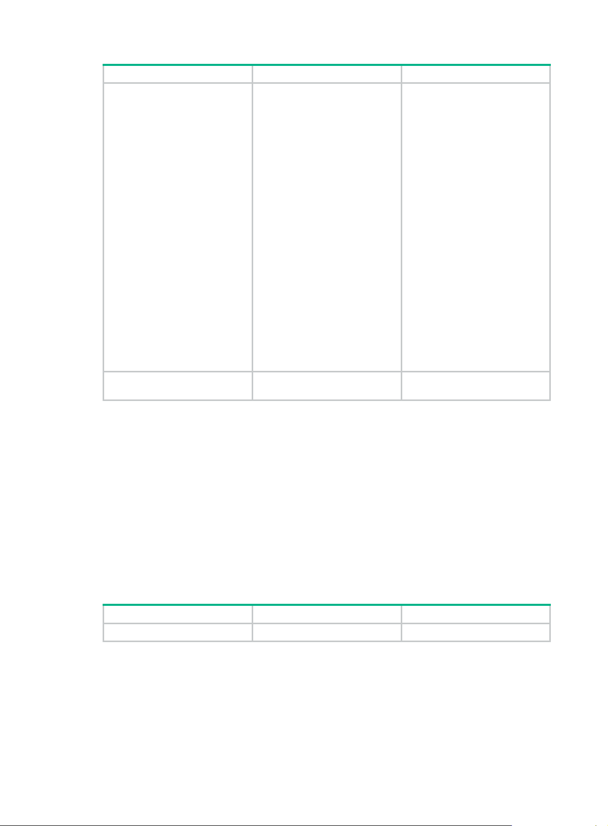
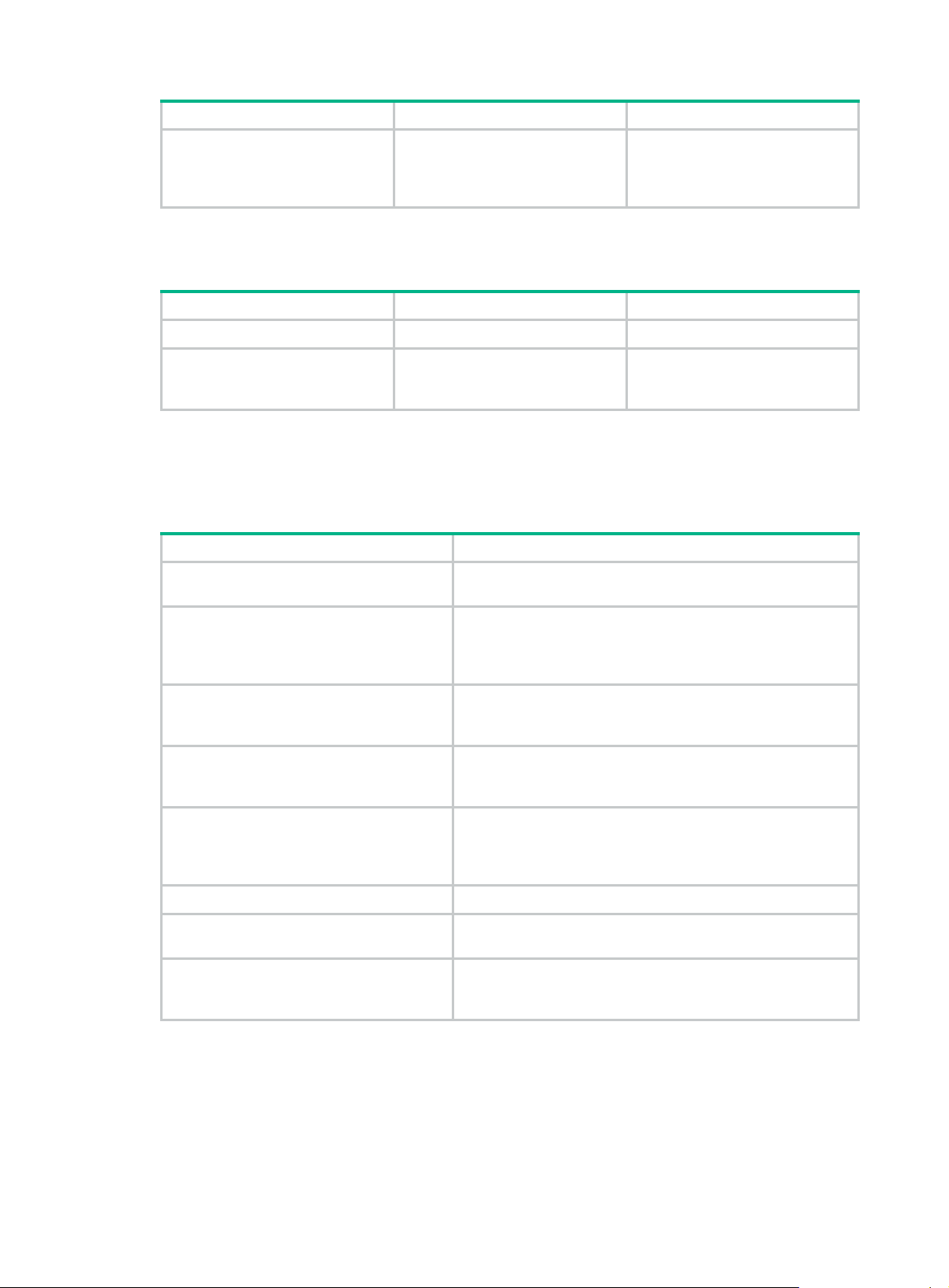
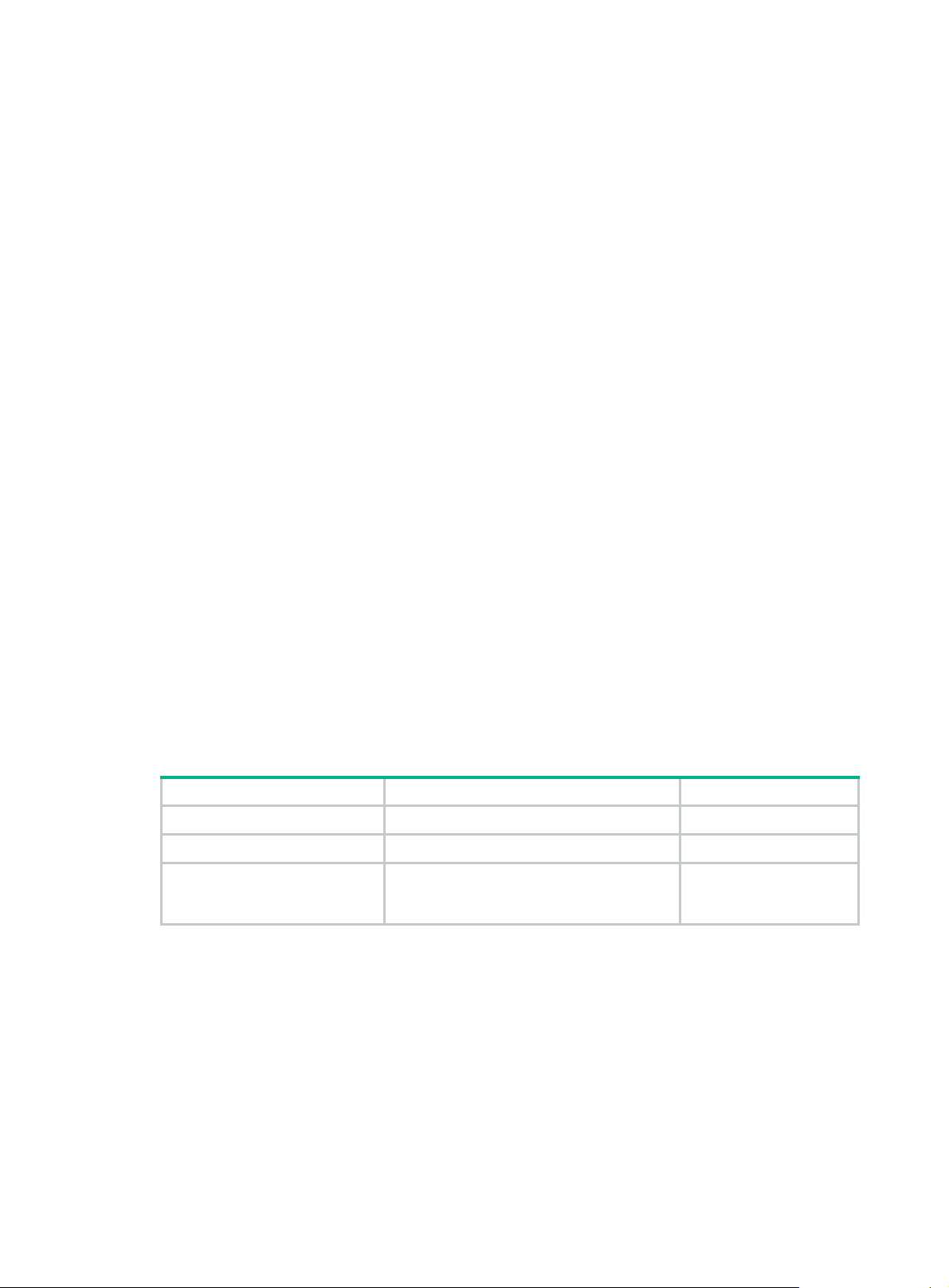
• auto—Sorts ACL rules in depth-first order. Depth-first ordering makes sure any subset of a rule
is always matched before the rule. Table 1 lists the se
quence of tie breakers that depth-first
ordering uses to sort rules for each type of ACL.
Table 1 Sort ACL rules in depth-first order
ACL type Sequence of tie breakers
1. VPN instance.
IPv4 basic ACL
IPv4 advanced ACL
IPv6 basic ACL
IPv6 advanced ACL
Layer 2 ACL
2. More 0s in the source IPv4 address wildcard (more 0s means a
narrower IPv4 address range).
3. Rule configured earlier.
1. VPN instance.
2. Specific protocol number.
3. More 0s in the source IPv4 address wildcard mask.
4. More 0s in the destination IPv4 address wildcard.
5. Narrower TCP/UDP service port number range.
6. Rule configured earlier.
1. VPN instance.
2. Longer prefix for the source IPv6 address (a longer prefix means a
narrower IPv6 address range).
3. Rule configured earlier.
1. VPN instance.
2. Specific protocol number.
3. Longer prefix for the source IPv6 address.
4. Longer prefix for the destination IPv6 address.
5. Narrower TCP/UDP service port number range.
6. Rule configured earlier.
1. More 1s in the source MAC address mask (more 1s means a smaller
MAC address).
2. More 1s in the destination MAC address mask.
3. Rule configured earlier.
A wildcard mask, also called an inverse mask, is a 32-bit binary number represented in dotted
decimal notation. In contrast to a network mask, the 0 bits in a wildcard mask represent "do care" bits,
and the 1 bits represent "don't care" bits. If the "do care" bits in an IP address are identical to the "do
care" bits in an IP address criterion, the IP address matches the criterion. All "don't care" bits are
ignored. The 0s and 1s in a wildcard mask can be noncontiguous. For example, 0.255.0.255 is a
valid wildcard mask.
Rule numbering
ACL rules can be manually numbered or automatically numbered. This section describes how
automatic ACL rule numbering works.
Rule numbering step
If you do not assign an ID to the rule you are creating, the system automatically assigns it a rule ID.
The rule numbering step sets the increment by which the system automatically numbers rules. For
example, the default ACL rule numbering step is 5. If you do not assign IDs to rules you are creating,
they are automatically numbered 0, 5, 10, 15, and so on. The wider the numbering step, the more
rules you can insert between two rules.
By introducing a gap between rules rather than contiguously numbering rules, you have the flexibility
of inserting rules in an ACL. This feature is important for a config-order ACL, where ACL rules are
matched in ascending order of rule ID.
2
Page 9

Automatic rule numbering and renumbering
The ID automatically assigned to an ACL rule takes the nearest higher multiple of the numbering step
to the current highest rule ID, starting with 0.
For example, if the step is 5, and there are five rules numbered 0, 5, 9, 10, and 12, the newly defined
rule is numbered 15. If the ACL does not contain a rule, the first rule is numbered 0.
Whenever the step changes, the rules are renumbered, starting from 0. For example, changing the
step from 5 to 2 renumbers rules 5, 10, 13, and 15 as rules 0, 2, 4, and 6.
Fragment filtering with ACLs
Traditional packet filtering matches only first fragments of packets, and allows all subsequent
non-first fragments to pass through. Attackers can fabricate non-first fragments to attack networks.
To avoid risks, the ACL feature is designed as follows:
• Filters all fragments by default, including non-first fragments.
• Allows for matching criteria modification for efficiency. For example, you can configure the ACL
to filter only non-first fragments.
Configuration restrictions and guidelines
When you configure ACLs, follow these restrictions and guidelines:
• Matching packets are forwarded through slow forwarding if an ACL rule contains match criteria
or has functions enabled in addition to the following match criteria and functions:
{ Source and destination IP addresses.
{ Source and destination ports.
{ Transport layer protocol.
{ ICMP or ICMPv6 message type, message code, and message name.
{ VPN instance.
{ Logging.
{ Time range.
Slow forwarding requires packets to be sent to the control plane for forwarding entry calculation,
which affects the device forwarding performance.
• On a border gateway in a VXLAN or EVPN network, an ACL applied to a Layer 3 Ethernet
interface or Layer 3 aggregate interface matches the packets on both the interface and its
subinterfaces. For information about VXLAN and EVPN, see VXLAN Configuration Guide and
EVPN Configuration Guide.
3
Page 10
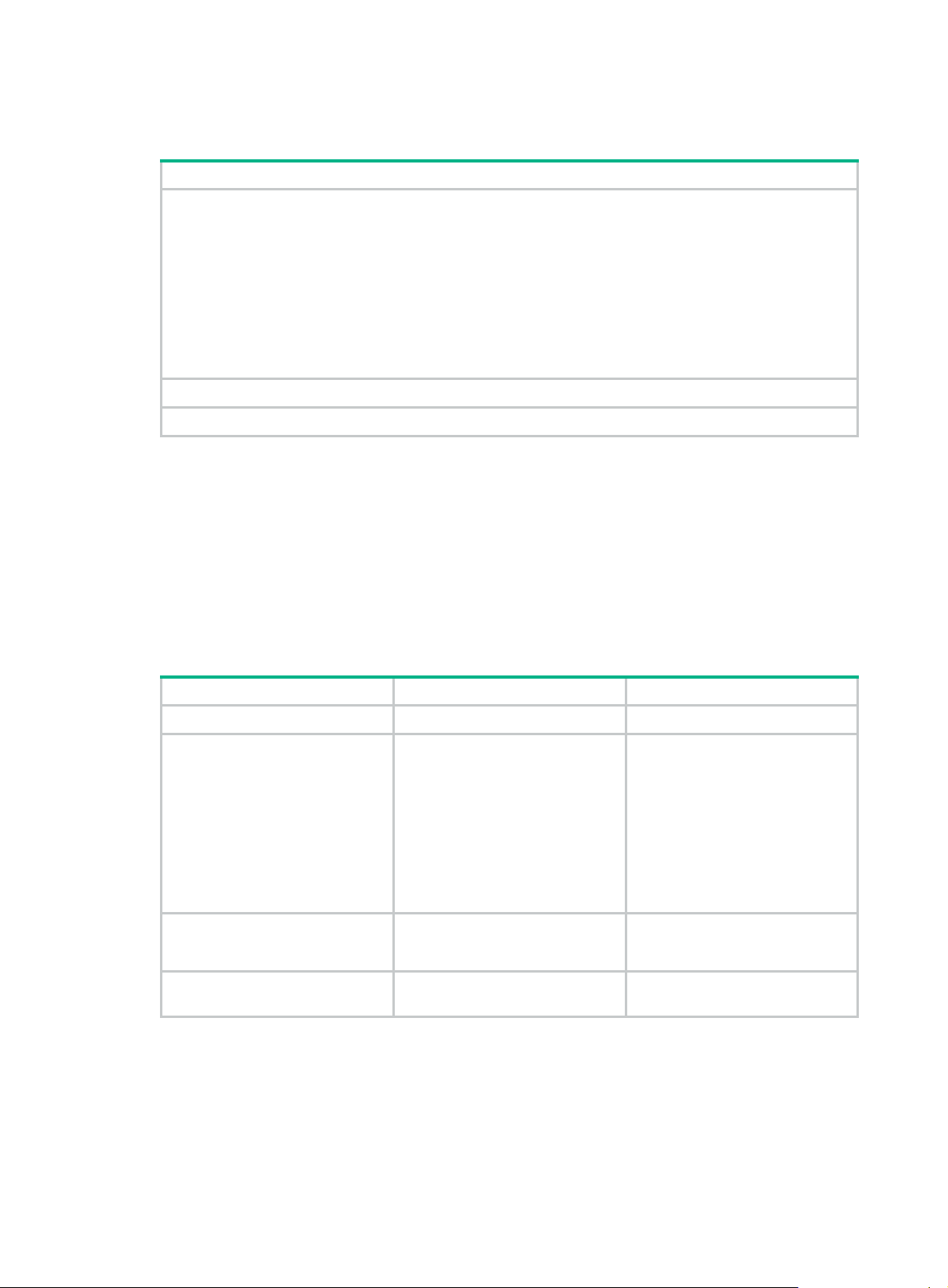
Configuration task list
Tasks at a glance
(Required.) Configure ACLs according to the characteristics of the packets to be matched:
• Configuring a basic ACL
{ Configuring an IPv4 basic ACL
{ Configuring an IPv6 basic ACL
• Configuring an advanced ACL
{ Configuring an IPv4 advanced ACL
{ Configuring an IPv6 advanced ACL
• Configuring a Layer 2 ACL
• Configuring a user-defined ACL
(Optional.) Copying an ACL
(Optional.) Configuring packet filtering with ACLs
Configuring a basic ACL
This section describes procedures for configuring IPv4 and IPv6 basic ACLs.
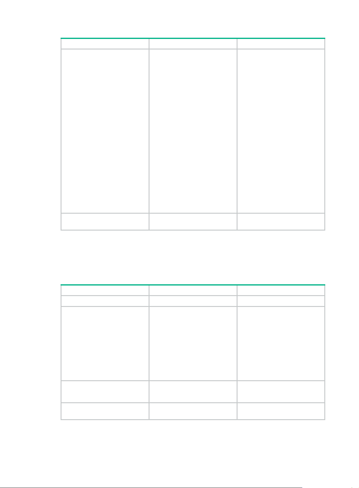
Configuring an IPv4 basic ACL
IPv4 basic ACLs match packets based only on source IP addresses.
To configure an IPv4 basic ACL:
Step Command Remarks
1. Enter system view.
2. Create an IPv4 basic ACL
and enter its view.
3. (Optional.) Configure a
description for the IPv4 basic
ACL.
4. (Optional.) Set the rule
numbering step.
system-view
acl basic
acl-name } [
config
description
step
start-value ]
{ acl-number |
} ]
step-value [
match-order
text
start
name
auto
{
N/A
By default, no ACLs exist.
The value range for a numbered
IPv4 basic ACL is 2000 to 2999.
Use the
|
command to enter the view of a
numbered IPv4 basic ACL.
Use the
command to enter the view of a
named IPv4 basic ACL.
By default, an IPv4 basic ACL
does not have a description.
By default, the rule numbering
step is 5 and the start rule ID is 0.
acl basic
acl basic name
acl-number
acl-name
4
Page 11
Step Command Remarks
By default, no IPv4 basic ACL
rules exist.
logging
5. Create or edit a rule.
6. (Optional.) Add or edit a rule
comment.
rule
[ rule-id ] {
counting
[
source
{ source-address
source-wildcard |
time-range
vpn-instance
vpn-instance-name ] *
rule
rule-id
deny
fragment
|
any
time-range-name |
comment
permit
|
|
} |
text
}
logging
The
only when the module (for
example, packet filtering) that
uses the ACL supports logging.
If an IPv4 basic ACL is used for
QoS traffic classification or packet
filtering in a VXLAN network, the
ACL matches packets as follows:
|
• The ACL matches outgoing
VXLAN packets by outer
IPv4 header information on a
VTEP.
• The ACL matches incoming
VXLAN packets by outer
IPv4 header information on
an intermediate transport
device.
• The ACL matches
de-encapsulated incoming
VXLAN packets by IPv4
header information on a
VTEP.
By default, no rule comment is
configured.
keyword takes effect
Configuring an IPv6 basic ACL
IPv6 basic ACLs match packets based only on source IP addresses.
To configure an IPv6 basic ACL:
Step Command Remarks
1. Enter system view.
2. Create an IPv6 basic ACL
view and enter its view.
3. (Optional.) Configure a
description for the IPv6 basic
ACL.
4. (Optional.) Set the rule
numbering step.
system-view
acl ipv6 basic
name
acl-name } [
auto
{
description
step
start-value ]
config
|
step-value [
{ acl-number |
match-order
} ]
text
start
N/A
By default, no ACLs exist.
The value range for a numbered
IPv6 basic ACL is 2000 to 2999.
Use the
acl-number command to enter the
view of a numbered IPv6 basic
ACL.
Use the
acl-name command to enter the
view of a named IPv6 basic ACL.
By default, an IPv6 basic ACL
does not have a description.
By default, the rule numbering
step is 5 and the start rule ID is 0.
acl ipv6 basic
acl ipv6 basic name
5
Page 12
Step Command Remarks
5. Create or edit a rule.
6. (Optional.) Add or edit a rule
comment.
rule
[ rule-id ] {
counting
[
routing
source
source-prefix |
source-address/source-prefix |
any
time-range-name |
vpn-instance-name ] *
rule
[
{ source-address
time-range
} |
rule-id
deny
fragment
|
type
routing-type ] |
comment
permit
|
|
vpn-instance
text
Configuring an advanced ACL
This section describes procedures for configuring IPv4 and IPv6 advanced ACLs.
Configuring an IPv4 advanced ACL
IPv4 advanced ACLs match packets based on the following criteria:
• Source IP addresses.
• Destination IP addresses.
• Packet priorities.
• Protocol numbers.
• Other protocol header information, such as TCP/UDP source and destination port numbers,
TCP flags, ICMP message types, and ICMP message codes.
}
logging
|
By default, no IPv6 basic ACL
rules exist.
logging
The
only when the module (for
example, packet filtering) that
uses the ACL supports logging.
By default, no rule comment is
configured.
keyword takes effect
Compared to IPv4 basic ACLs, IPv4 advanced ACLs allow more flexible and accurate filtering.
To configure an IPv4 advanced ACL:
Step Command Remarks
1. Enter system view.
2. Create an IPv4 advanced
ACL and enter its view.
3. (Optional.) Configure a
description for the IPv4
advanced ACL.
4. (Optional.) Set the rule
numbering step.
system-view
acl advanced
name
acl-name } [
auto
{
description
step
start-value ]
config
|
step-value [
{ acl-number |
match-order
} ]
text
start
N/A
By default, no ACLs exist.
The value range for a numbered
IPv4 advanced ACL is 3000 to
3999.
Use the
acl-number command to enter the
view of a numbered IPv4
advanced ACL.
Use the
acl-name command to enter the
view of a named IPv4 advanced
ACL.
By default, an IPv4 advanced ACL
does not have a description.
By default, the rule numbering
step is 5 and the start rule ID is 0.
acl advanced
acl advanced name
6
Page 13
Step Command Remarks
By default, no IPv4 advanced ACL
rules exist.
logging
5. Create or edit a rule.
6. (Optional.) Add or edit a rule
comment.
rule
[ rule-id ] {
protocol [ { {
fin-value |
rst-value |
urg-value } * |
counting
{ dest-address dest-wildcard |
any
destination-port
} |
port1 [ port2 ] | {
precedence
{
tos } * } |
{ icmp-type [ icmp-code ] |
icmp-message } |
source
{ source-address
source-wildcard |
source-port
[ port2 ] |
ange-name |
time-r
vpn-instance-name ] *
rule
rule-id
deny
ack
ack-value |
psh
psh-value |
syn
syn-value |
established
destination
|
dscp
precedence |
fragment
time-range
|
logging
any
operator port1
comment
permit
|
rst
urg
} |
operator
dscp |
tos
icmp-type
|
} |
vpn-instance
text
fin
The
only when the module (for
}
example, packet filtering) that
uses the ACL supports logging.
If an IPv4 advanced ACL is used
for QoS traffic classification or
packet filtering in a VXLAN
network, the ACL matches
packets as follows:
• The ACL matches outgoing
VXLAN packets by outer
IPv4 header information on a
VTEP.
• The ACL matches incoming
VXLAN packets by outer
IPv4 header information on
an intermediate transport
device.
• The ACL matches
de-encapsulated incoming
VXLAN packets by IPv4
header information on a
VTEP.
By default, no rule comment is
configured.
keyword takes effect
Configuring an IPv6 advanced ACL
IPv6 advanced ACLs match packets based on the following criteria:
• Source IPv6 addresses.
• Destination IPv6 addresses.
• Packet priorities.
• Protocol numbers.
• Other protocol header fields such as the TCP/UDP source port number, TCP/UDP destination
port number, ICMPv6 message type, and ICMPv6 message code.
Compared to IPv6 basic ACLs, IPv6 advanced ACLs allow more flexible and accurate filtering.
To configure an IPv6 advanced ACL:
Step Command Remarks
1. Enter system view.
system-view
N/A
7
Page 14

Step Command Remarks
By default, no ACLs exist.
The value range for a numbered
IPv6 advanced ACL is 3000 to
3999.
2. Create an IPv6 advanced
ACL and enter its view.
3. (Optional.) Configure a
description for the IPv6
advanced ACL.
4. (Optional.) Set the rule
numbering step.
acl ipv6 advanced
name
acl-name } [
auto
{
description
step
start-value ]
config
|
step-value [
} ]
text
{ acl-number |
match-order
start
Use the
acl-number command to enter the
view of a numbered IPv6
advanced ACL.
Use the
acl-name command to enter the
view of a named IPv6 advanced
ACL.
By default, an IPv6 advanced ACL
does not have a description.
By default, the rule numbering
step is 5 and the start rule ID is 0.
acl ipv6 advanced
acl ipv6 advanced name
rule
[ rule-id ] {
ack
psh
psh-value |
syn
syn-value |
established
destination
|
dscp
dscp |
{ icmp6-type
routing
|
hop-by-hop
source
source-port
comment
5. Create or edit a rule.
6. (Optional.) Add or edit a rule
comment.
protocol [ { {
fin-value |
rst-value |
urg-value } * |
counting
{ dest-address dest-prefix |
dest-address/dest-prefix |
destination-port
[ port2 ] |
flow-label-value |
icmp6-type
icmp6-code | icmp6-message } |
logging
routing-type ] |
hop-type ] |
{ source-address source-prefix |
source-address/source-prefix |
y
an
} |
time-range-name |
vpn-instance-name ] *
rule
rule-id
Configuring a Layer 2 ACL
deny
permit
|
ack-value |
rst
urg
} |
any
operator port1
flow-label
fragment
type
[
|
vpn-instance
|
time-range
text
[
}
fin
} |
type
By default, no IPv6 advanced ACL
rules exist.
logging
The
only when the module (for
example, packet filtering) that
uses the ACL supports logging.
If an IPv6 advanced ACL is used
for outbound QoS traffic
classification or packet filtering,
do not specify the
parameter.
If an IPv6 advanced ACL is used
for packet filtering, do not specify
fragment
the
By default, no rule comment is
configured.
keyword takes effect
flow-label
keyword.
Layer 2 ACLs, also called "Ethernet frame header ACLs," match packets based on Layer 2 Ethernet
header fields, such as:
• Source MAC address.
• Destination MAC address.
• 802.1p priority (VLAN priority).
• Link layer protocol type.
To configure a Layer 2 ACL:
8
Page 15
Step Command Remarks
1. Enter system view.
2. Create a Layer 2 ACL and
enter its view.
3. (Optional.) Configure a
description for the Layer 2
ACL.
4. (Optional.) Set the rule
numbering step.
system-view N/A
By default, no ACLs exist.
The value range for a numbered
Layer 2 ACL is 4000 to 4999.
acl mac
acl-name } [
config
description
step
start-value ]
{ acl-number |
} ]
step-value [
match-order
text
start
name
{
auto
Use the
|
command to enter the view of a
numbered Layer 2 ACL.
Use the
command to enter the view of a
named Layer 2 ACL.
By default, a Layer 2 ACL does
not have a description.
By default, the rule numbering
step is 5 and the start rule ID is 0.
acl mac
acl mac name
acl-number
acl-name
5. Create or edit a rule.
6. (Optional.) Add or edit a rule
comment.
rule
[ rule-id ] {
cos
[
dot1p |
dest-address dest-mask | {
lsap-type lsap-type-mask |
protocol-type
protocol-type-mask } |
source-mac
source-mask |
time-range-name ] *
rule
rule-id
deny
permit
|
counting
source-address
time-range
comment
dest-mac
|
text
lsap
type
Configuring a user-defined ACL
User-defined ACLs allow you to customize rules based on information in protocol headers. You can
define a user-defined ACL to match packets. A specific number of bytes after an offset (relative to the
specified header) are compared against a match pattern after being ANDed with a match pattern
mask.
To configure a user-defined ACL:
Step Command Remarks
1. Enter system view.
system-view
}
By default
exist.
By default, no rule comment is
configured.
N/A
,
no Layer 2 ACL rules
2. Create a user-defined ACL
and enter its view.
3. (Optional.) Configure a
description for the
user-defined ACL.
acl user-defined
name
acl-name }
description
text
9
{ acl-number |
By default, no ACLs exist.
The value range for a numbered
user-defined ACL is 5000 to 5999.
Use the
acl-number command to enter the
view of a numbered user-defined
ACL.
Use the
acl-name command to enter the
view of a named user-defined
ACL.
By default, a user-defined ACL
does not have a description.
acl user-defined
acl user-defined name
Page 16
Step Command Remarks
4. Create or edit a rule.
5. (Optional.) Add or edit a rule
comment.
Copying an ACL
You can create an ACL by copying an existing ACL (source ACL). The new ACL (destination ACL)
has the same properties and content as the source ACL, but uses a different number or name than
the source ACL.
To successfully copy an ACL, make sure:
• The destination ACL number is from the same type as the source ACL number.
• The source ACL already exists, but the destination ACL does not.
To copy an ACL:
Step Command
1. Enter system view.
rule
[ rule-id ] {
l2
[ {
rule-string rule-mask
offset }&<1-8> ] [
time-range
rule
time-range-name ] *
comment
rule-id
deny
permit
|
counting
text
system-view
}
By default, no user-defined ACL
|
rules exist.
By default, no rule comment is
configured.
acl
ipv6
2. Copy an existing ACL to create a new ACL.
[
{ source-acl-number |
{ dest-acl-number |
mac | user-defined
|
name
name
dest-acl-name }
]
source-acl-name }
Configuring packet filtering with ACLs
This section describes procedures for using an ACL to filter packets. For example, you can apply an
ACL to an interface to filter incoming or outgoing packets.
NOTE:
• The packet filtering feature is available on Layer 2 Ethernet interfaces, Layer 2 aggregate
interfaces, Layer 3 Ethernet interfaces, Layer 3 Ethernet subinterfaces, Layer 3 aggregate
interfaces, VLAN interfaces, and VSI interfaces.
• For VSI interfaces, the packet filtering feature is available in Release 2510P01 and later.
• The term "interface" in this section collectively refers to these types of interfaces. You can use the
port link-mode command to configure an Ethernet port as a Layer 2 or Layer 3 interface (see
Layer 2—LAN Switching Configuration Guide).
Applying an ACL to an interface for packet filtering
copy
to
Step Command Remarks
1. Enter system view.
2. Enter interface view.
system-view
interface
interface-number
interface-type
10
N/A
N/A
Page 17
Step Command Remarks
By default, an interface does not
filter packets.
To the same direction of an
interface, you can apply a
3. Apply an ACL to the interface
to filter packets.
packet-filter
user-defined
name
acl-name } {
outbound
ipv6
[
} [
mac
|
] { acl-number |
inbound
hardware-count ]
|
|
maximum of four ACLs: one IPv4
ACL, one IPv6 ACL, one Layer 2
ACL, and one user-defined ACL.
You cannot apply an ACL to the
outbound direction of a Layer 2
aggregate interface, Layer 3
aggregate interface, or VSI
interface.
Configuring the applicable scope of packet filtering on a VLAN interface
You can configure the packet filtering on a VLAN interface to filter the following packets:
• Packets forwarded at Layer 3 by the VLAN interface.
• All packets, including packets forwarded at Layer 3 by the VLAN interface and packets
forwarded at Layer 2 by the physical ports associated with the VLAN interface.
To configure the applicable scope of packet filtering on a VLAN interface:
Step Command Remarks
1. Enter system view.
2. Create a VLAN interface
and enter its view.
3. Specify the applicable
scope of packet filtering on
the VLAN interface.
system-view
interface vlan-interface
vlan-interface-id
packet-filter filter
route
[
N/A
all ]
|
If the VLAN interface already exists,
you directly enter its view.
By default, no VLAN interface exists.
By default, the packet filtering filters
all packets.
Configuring logging and SNMP notifications for packet filtering
You can configure the ACL module to generate log entries or SNMP notifications for packet filtering
and output them to the information center or SNMP module at the output interval. The log entry or
notification records the number of matching packets and the matched ACL rules. If an ACL is
matched for the first time, the device immediately outputs a log entry or notification to record the
matching packet.
For more information about the information center and SNMP, see Network Management and
Monitoring Configuration Guide.
To configure logging and SNMP notifications for packet filtering:
Step Command Remarks
1. Enter system view.
system-view
11
N/A
Page 18
Step Command Remarks
2. Set the interval for outputting
packet filtering logs or
notifications.
acl
logging
{
interval
trap
|
interval
}
Setting the packet filtering default action
Step Command Remarks
1. Enter system view.
system-view
The default setting is 0 minutes.
By default, the device does not
generate log entries or SNMP
notifications for packet filtering.
N/A
2. Set the packet filtering
default action to deny.
packet-filter default deny
Displaying and maintaining ACLs
Execute display commands in any view and reset commands in user view.
Task Command
Display ACL configuration and match
statistics.
Display ACL application information for
packet filtering.
Display match statistics for packet filtering
ACLs.
Display the accumulated statistics for
packet filtering ACLs.
Display detailed ACL packet filtering
information.
display acl
name
display packet-filter
interface-number ] [
vlan-interface
slot
[
slot-number ] }
display packet-filter statistics interface
interface-number {
user-defined
display packet-filter statistics sum
ipv6
[
|
brief ]
[
display packet-filter verbose interface
interface-number {
user-defined
slot-number ]
ipv6
[
acl-name }
mac | user-defined
mac | user-defined
|
{
inbound
vlan-interface-number [
inbound
] { acl-number |
inbound
] { acl-number |
By default, the packet filter
permits packets that do not match
any ACL rule to pass.
] { acl-number |
interface
[ interface-type
outbound
|
outbound
|
name
] { acl-number |
outbound
|
name
] |
inbound
interface-type
} [ [
acl-name } ] [
inbound
{
interface-type
} [ [
acl-name } ]
interface
outbound
|
ipv6
mac
|
brief
outbound
|
name
acl-name }
ipv6 | mac
[ slot
all
|
]
|
]
}
|
Display QoS and ACL resource usage.
Clear ACL statistics.
Clear match statistics and accumulated
match statistics for packet filtering ACLs.
display qos-acl resource
reset acl
all
|
reset packet-filter statistics interface
interface-number ] {
user-defined
12
name
ipv6
[
mac | user-defined
|
acl-name }
] { acl-number |
inbound
slot
[
slot-number ]
]
outbound
|
name
acl-name } ]
counter
[ interface-type
{ acl-number |
ipv6 | mac
} [ [
|
Page 19
ACL configuration examples
Interface-based packet filter configuration example
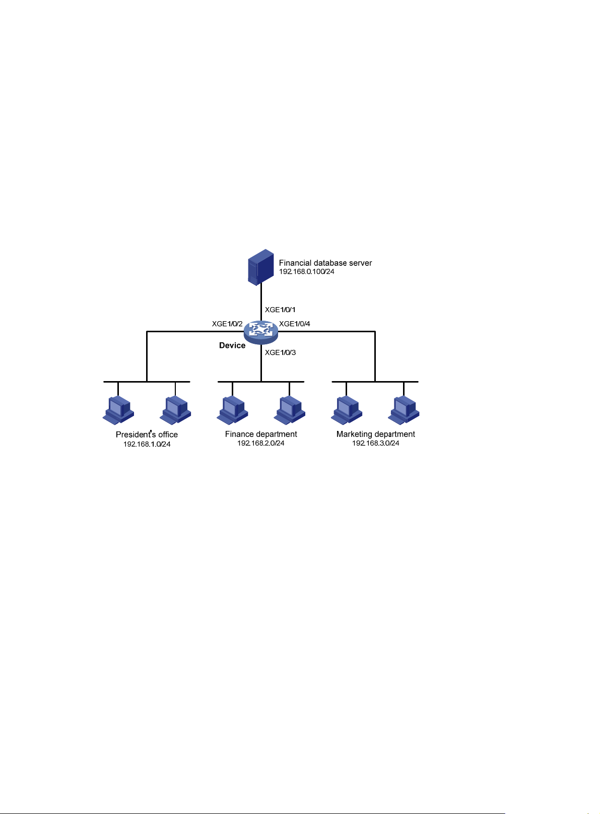
Network requirements
A company interconnects its departments through the device. Configure a packet filter to:
• Permit access from the President's office at any time to the financial database server.
• Permit access from the Finance department to the database server only during working hours
(from 8:00 to 18:00) on working days.
• Deny access from any other department to the database server.
Figure 1 Network diagram
Configuration procedure
# Create a periodic time range from 8:00 to 18:00 on working days.
<Device> system-view
[Device] time-range work 08:0 to 18:00 working-day
# Create an IPv4 advanced ACL numbered 3000.
[Device] acl advanced 3000
# Configure a rule to permit access from the President's office to the financial database server.
[Device-acl-ipv4-adv-3000] rule permit ip source 192.168.1.0 0.0.0.255 destination
192.168.0.100 0
# Configure a rule to permit access from the Finance department to the database server during
working hours.
[Device-acl-ipv4-adv-3000] rule permit ip source 192.168.2.0 0.0.0.255 destination
192.168.0.100 0 time-range work
# Configure a rule to deny access to the financial database server.
[Device-acl-ipv4-adv-3000] rule deny ip source any destination 192.168.0.100 0
[Device-acl-ipv4-adv-3000] quit
# Apply IPv4 advanced ACL 3000 to filter outgoing packets on interface Ten-GigabitEthernet 1/0/1.
[Device] interface ten-gigabitethernet 1/0/1
[Device-Ten-GigabitEthernet1/0/1] packet-filter 3000 outbound
13
Page 20

[Device-Ten-GigabitEthernet1/0/1] quit
Verifying the configuration
# Verify that a PC in the Finance department can ping the database server during working hours. (All
PCs in this example use Windows XP).
C:\> ping 192.168.0.100
Pinging 192.168.0.100 with 32 bytes of data:
Reply from 192.168.0.100: bytes=32 time=1ms TTL=255
Reply from 192.168.0.100: bytes=32 time<1ms TTL=255
Reply from 192.168.0.100: bytes=32 time<1ms TTL=255
Reply from 192.168.0.100: bytes=32 time<1ms TTL=255
Ping statistics for 192.168.0.100:
Packets: Sent = 4, Received = 4, Lost = 0 (0% loss),
Approximate round trip times in milli-seconds:
Minimum = 0ms, Maximum = 1ms, Average = 0ms
# Verify that a PC in the Marketing department cannot ping the database server during working
hours.
C:\> ping 192.168.0.100
Pinging 192.168.0.100 with 32 bytes of data:
Request timed out.
Request timed out.
Request timed out.
Request timed out.
Ping statistics for 192.168.0.100:
Packets: Sent = 4, Received = 0, Lost = 4 (100% loss),
# Display configuration and match statistics for IPv4 advanced ACL 3000 on the device during
working hours.
[Device] display acl 3000
Advanced IPv4 ACL 3000, 3 rules,
ACL's step is 5
rule 0 permit ip source 192.168.1.0 0.0.0.255 destination 192.168.0.100 0
rule 5 permit ip source 192.168.2.0 0.0.0.255 destination 192.168.0.100 0 time-range work
(Active)
rule 10 deny ip destination 192.168.0.100 0
The output shows that rule 5 is active.
14
Page 21

QoS overview
In data communications, Quality of Service (QoS) provides differentiated service guarantees for
diversified traffic in terms of bandwidth, delay, jitter, and drop rate, all of which can affect QoS.
QoS manages network resources and prioritizes traffic to balance system resources.
The following section describes typical QoS service models and widely used QoS techniques.
QoS service models
This section describes several typical QoS service models.
Best-effort service model
The best-effort model is a single-service model. The best-effort model is not as reliable as other
models and does not guarantee delay-free delivery.
The best-effort service model is the default model for the Internet and applies to most network
applications. It uses the First In First Out (FIFO) queuing mechanism.
IntServ model
The integrated service (IntServ) model is a multiple-service model that can accommodate diverse
QoS requirements. This service model provides the most granularly differentiated QoS by identifying
and guaranteeing definite QoS for each data flow.
In the IntServ model, an application must request service from the network before it sends data.
IntServ signals the service request with the RSVP. All nodes receiving the request reserve resources
as requested and maintain state information for the application flow.
The IntServ model demands high storage and processing capabilities because it requires all nodes
along the transmission path to maintain resource state information for each flow. This model is
suitable for small-sized or edge networks. However, it is not suitable for large-sized networks, for
example, the core layer of the Internet, where billions of flows are present.
DiffServ model
The differentiated service (DiffServ) model is a multiple-service model that can meet diverse QoS
requirements. It is easy to implement and extend. DiffServ does not signal the network to reserve
resources before sending data, as IntServ does.
QoS techniques overview
The QoS techniques include the following features:
• Traffic classification.
• Traffic policing.
• Traffic shaping.
• Rate limit.
• Congestion management.
• Congestion avoidance.
15
Page 22
The following section briefly introduces these QoS techniques.
All QoS techniques in this document are based on the DiffServ model.
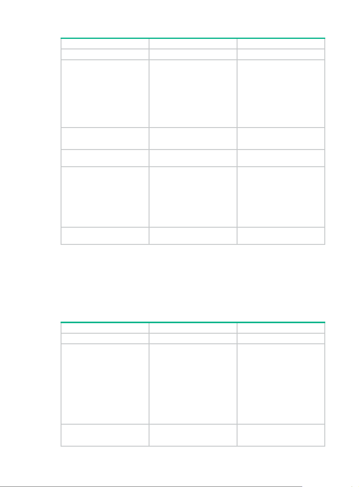
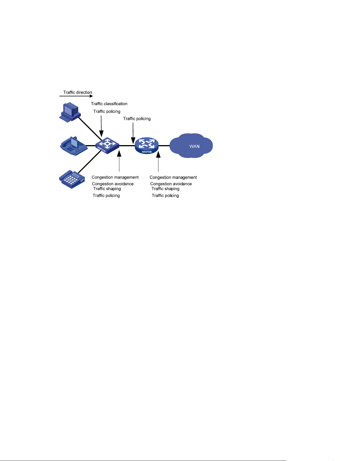
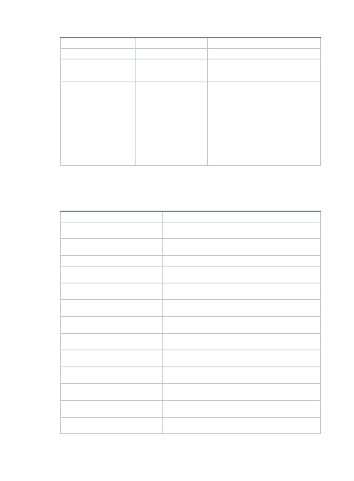
Deploying QoS in a network
Figure 2 Position of the QoS techniques in a network
As shown in Figure 2, traffic classification, traffic shaping, traffic policing, congestion management,
and congestion avoidance mainly implement the following functions:
• Traffic classification—Uses match criteria to assign packets with the same characteristics to
a traffic class. Based on traffic classes, you can provide differentiated services.
• Traffic policing—Polices flows and imposes penalties to prevent aggressive use of network
resources. You can apply traffic policing to both incoming and outgoing traffic of a port.
• Traffic shaping—Adapts the output rate of traffic to the network resources available on the
downstream device to eliminate packet drops. Traffic shaping usually applies to the outgoing
traffic of a port.
• Congestion management—Provides a resource scheduling policy to determine the packet
forwarding sequence when congestion occurs. Congestion management usually applies to the
outgoing traffic of a port.
• Congestion avoidance—Monitors the network resource usage. It is usually applied to the
outgoing traffic of a port. When congestion worsens, congestion avoidance reduces the queue
length by dropping packets.
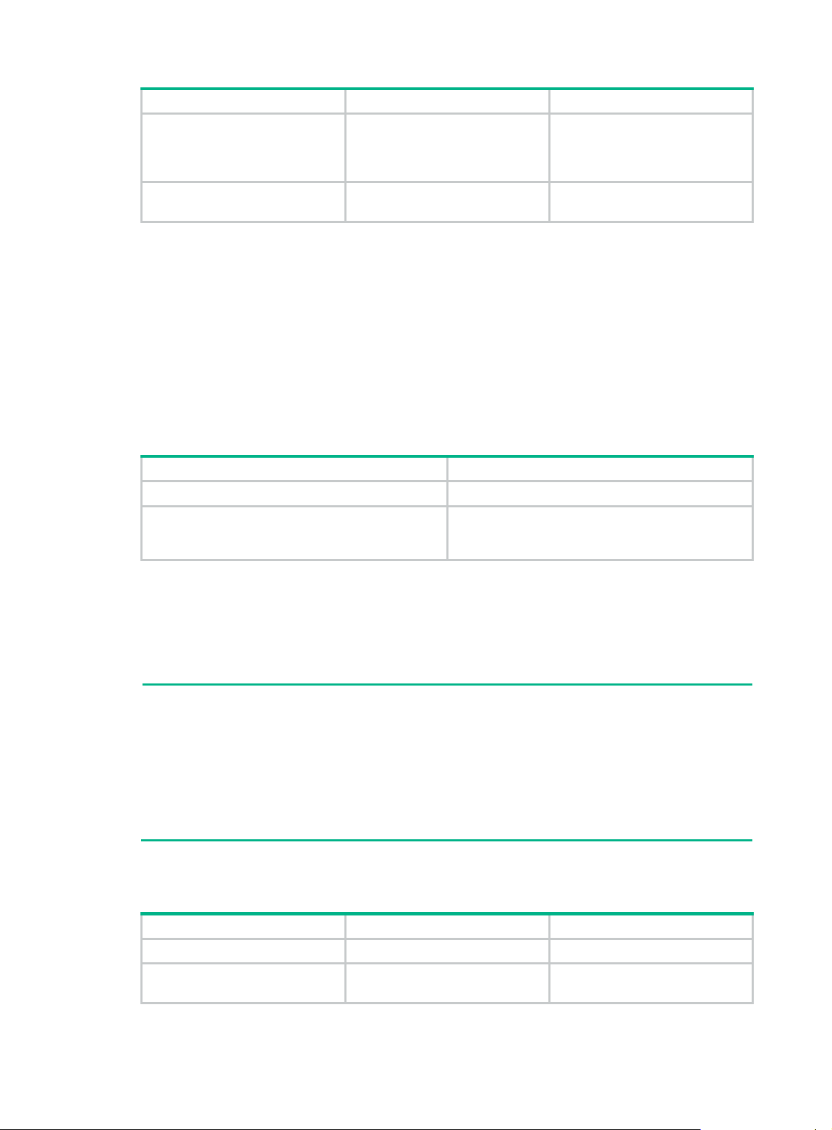
QoS processing flow in a device
Figure 3 briefly describes how the QoS module processes traffic.
1. Traffic classifier identifies and classifies traffic for subsequent QoS actions.
2. The QoS module takes various QoS actions on classified traffic as configured, depending on
the traffic processing phase and network status. For example, you can configure the QoS
module to perform the following operations:
{ Traffic policing for incoming traffic.
{ Traffic shaping for outgoing traffic.
{ Congestion avoidance before congestion occurs.
{ Congestion management when congestion occurs.
16
Page 23
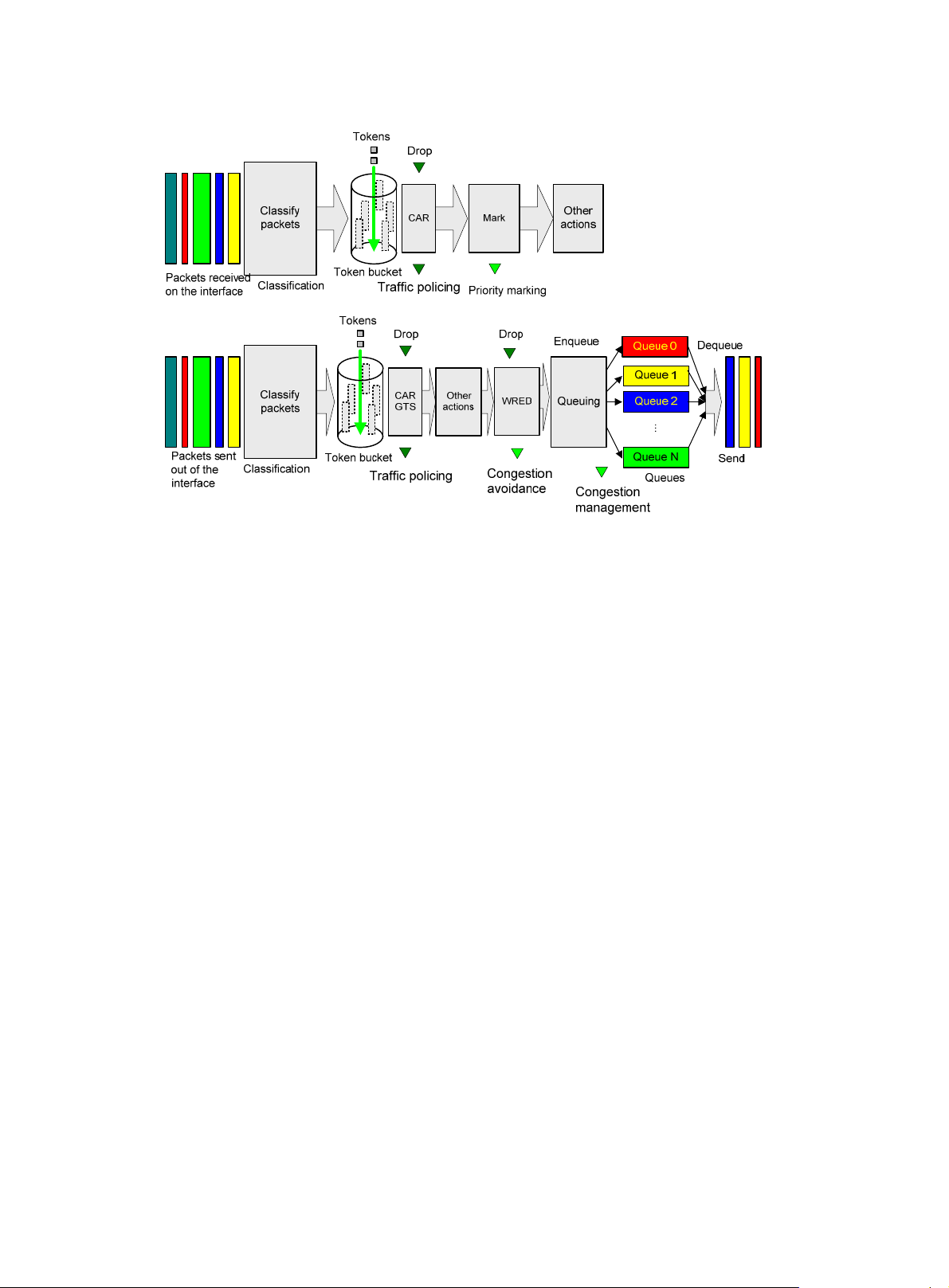
Figure 3 QoS processing flow
17
Page 24
Configuring a QoS policy
You can configure QoS by using the MQC approach or non-MQC approach.
Non-MQC approach
In the non-MQC approach, you configure QoS service parameters without using a QoS policy. For
example, you can use the rate limit feature to set a rate limit on an interface without using a QoS
policy.
MQC approach
In the modular QoS configuration (MQC) approach, you configure QoS service parameters by using
QoS policies. A QoS policy defines the policing or other QoS actions to take on different classes of
traffic. It is a set of class-behavior associations.
A traffic class is a set of match criteria for identifying traffic, and it uses the AND or OR operator.
• If the operator is AND, a packet must match all the criteria to match the traffic class.
• If the operator is OR, a packet matches the traffic class if it matches any of the criteria in the
traffic class.
A traffic behavior defines a set of QoS actions to take on packets, such as priority marking and
redirect.
By associating a traffic behavior with a traffic class in a QoS policy, you apply QoS actions in the
traffic behavior to the traffic class.
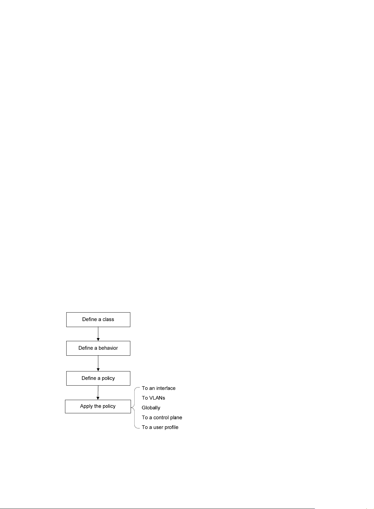
Configuration procedure diagram
Figure 4 shows how to configure a QoS policy.
Figure 4 QoS policy configuration procedure
18
Page 25
Defining a traffic class
Step Command Remarks
1. Enter system view.
2. Create a traffic class and
enter traffic class view.
3. Configure a match criterion.
system-view
traffic classifier
operator { and | or
[
if-match
match-criteria
Defining a traffic behavior
A traffic behavior is a set of QoS actions (such as traffic filtering, shaping, policing, and priority
marking) to take on a traffic class.
To define a traffic behavior:
classifier-name
} ]
N/A
By default, no traffic classes exist.
By default, no match criterion is
configured.
For more information, see the
if-match
QoS Command Reference.
command in ACL and
Step Command Remarks
1. Enter system view.
2. Create a traffic behavior and
enter traffic behavior view.
3. Configure an action in the
traffic behavior.
system-view
traffic behavior
See the subsequent chapters,
depending on the purpose of the
traffic behavior: traffic policing,
traffic filtering, priority marking,
traffic accounting, and so on.
Defining a QoS policy
To perform actions defined in a behavior for a class of packets, associate the behavior with the class
in a QoS policy.
To associate a traffic class with a traffic behavior in a QoS policy:
Step Command Remarks
1. Enter system view.
2. Create a QoS policy and
enter QoS policy view.
system-view
qos policy
N/A
behavior-name
policy-name By default, no QoS policies exist.
By default, no traffic behaviors
exist.
By default, no action is configured
for a traffic behavior.
N/A
3. Associate a traffic class with
a traffic behavior to create a
class-behavior association
in the QoS policy.
classifier
behavior
insert-before
[
before-classifier-name ]
classifier-name
behavior-name
19
By default, a traffic class is not
associated with a traffic behavior.
Repeat this step to create more
class-behavior associations.
Page 26
Applying the QoS policy
You can apply a QoS policy to the following destinations:
• Interface—The QoS policy takes effect on the traffic sent or received on the interface.
• VLAN—The QoS policy takes effect on the traffic sent or received on all ports in the VLAN.
• Globally—The QoS policy takes effect on the traffic sent or received on all ports.
• Control plane—The QoS policy takes effect on the traffic received on the control plane.
• User profile—The QoS policy takes effect on the traffic sent or received by the online users of
the user profile.
You can modify traffic classes, traffic behaviors, and class-behavior associations in a QoS policy
even after it is applied (except that it is applied to a user profile). If a traffic class uses an ACL for
traffic classification, you can delete or modify the ACL.
Applying the QoS policy to an interface
A QoS policy can be applied to multiple interfaces. However, only one QoS policy can be applied to
one direction (inbound or outbound) of an interface.
The QoS policy applied to the outgoing traffic on an interface does not regulate local packets. Local
packets refer to critical protocol packets sent by the local system for operation maintenance. The
most common local packets include link maintenance, routing, LDP, RSVP, and SSH packets.
QoS policies can be applied to Layer 2/Layer 3 Ethernet interfaces, Layer 3 Ethernet subinterfaces,
Layer 2/Layer 3 aggregate interfaces, and VSI interfaces.
For VSI interfaces, the QoS policy application feature is available in Release 2510P01 and later.
The term "interface" in this section collectively refers to these types of interfaces. You can use the
port link-mode command to configure an Ethernet port as a Layer 2 or Layer 3 interface (see Layer
2—LAN Switching Configuration Guide).
On a border gateway in a VXLAN or EVPN network:
• If a QoS policy without VLAN ID match criteria is applied to a Layer 3 Ethernet interface, the
QoS policy also takes effect on its subinterfaces.
• If a QoS policy is applied to any other interface, the match criteria for untagged packets
forwarded at Layer 3 do not take effect if the following conditions exist:
{ A class contains an inner or outer VLAN ID match criterion.
{ The class also contains match criteria configured to match untagged packets forwarded at
Layer 3.
For information about VXLAN and EVPN, see VXLAN Configuration Guide and EVPN Configuration
Guide.
To apply a QoS policy to an interface:
Step Command Remarks
1. Enter system view.
2. Enter interface view.
system-view
interface
interface-type interface-number
N/A
N/A
20
Page 27
Step Command Remarks
3. Apply the QoS policy to
the interface.
qos apply policy
outbound
}
policy-name {
Applying the QoS policy to VLANs
You can apply a QoS policy to VLANs to regulate traffic of the VLANs.
Configuration restrictions and guidelines
When you apply a QoS policy to VLANs, follow these restrictions and guidelines:
• QoS policies cannot be applied to dynamic VLANs, including VLANs created by GVRP.
• If the hardware resources of an IRF member device are insufficient, applying a QoS policy to
VLANs might fail on the IRF member device. The system does not automatically roll back the
QoS policy configuration already applied to other IRF member devices. To ensure consistency,
use the undo qos vlan-policy vlan command to manually remove the QoS policy
configuration applied to them.
inbound
By default, no QoS policy is
applied to an interface.
You cannot apply a QoS
|
policy to the outbound
direction of a Layer 2
aggregate interface, Layer 3
aggregate interface, or VSI
interface.
Configuration procedure
To apply the QoS policy to VLANs:
Step Command Remarks
1. Enter system view.
2. Apply the QoS policy to
VLANs.
system-view
qos vlan-policy
vlan-id-list {
inbound | outbound
policy-name
Applying the QoS policy globally
You can apply a QoS policy globally to the inbound or outbound direction of all ports.
If the hardware resources of an IRF member device are insufficient, applying a QoS policy globally
might fail on the IRF member device. The system does not automatically roll back the QoS policy
configuration already applied to other IRF member devices. To ensure consistency, use the undo
qos apply policy global command to manually remove the QoS policy configuration applied to
them.
To apply the QoS policy globally:
Step Command Remarks
1. Enter system view.
2. Apply the QoS policy
globally.
system-view
qos apply policy
global { inbound | outbound }
policy-name
vlan
N/A
By default, no QoS policy is applied
}
to a VLAN.
N/A
By default, no QoS policy is applied
globally.
Applying the QoS policy to a control plane
A device provides the data plane and the control plane.
21
Page 28
• Data plane—The units at the data plane are responsible for receiving, transmitting, and
switching (forwarding) packets, such as various dedicated forwarding chips. They deliver super
processing speeds and throughput.
• Control plane—The units at the control plane are processing units running most routing and
switching protocols. They are responsible for protocol packet resolution and calculation, such
as CPUs. Compared with data plane units, the control plane units allow for great packet
processing flexibility but have lower throughput.
When the data plane receives packets that it cannot recognize or process, it transmits them to the
control plane. If the transmission rate exceeds the processing capability of the control plane, the
control plane will be busy handling undesired packets. As a result, the control plane will fail to handle
legitimate packets correctly or timely. As a result, protocol performance is affected.
To address this problem, apply a QoS policy to the control plane to take QoS actions, such as traffic
filtering or rate limiting, on inbound traffic. This ensures that the control plane can correctly receive,
transmit, and process packets.
A predefined control plane QoS policy uses the protocol type or protocol group type to identify the
type of packets sent to the control plane. You can use protocol types or protocol group types in
if-match commands in traffic class view for traffic classification. Then you can reconfigure traffic
behaviors for these traffic classes as required. You can use the display qos policy control-plane
pre-defined command to display predefined control plane QoS policies.
Configuration restrictions and guidelines
When you apply a QoS policy to a control plane, follow these restrictions and guidelines:
• If the hardware resources of IRF member device are insufficient, applying a QoS policy globally
might fail on the IRF member device. The system does not automatically roll back the QoS
policy configuration already applied to other IRF member devices. To ensure consistency, use
the undo qos apply policy command to manually remove the QoS policy configuration applied
to them.
• If a class uses control plane protocols or control plane protocol groups as match criteria, the
action in the associated traffic behavior can only be car or the combination of car and
accounting packet. Only the cir keyword in the car action can be applied correctly.
Configuration procedure
To apply the QoS policy to a control plane:
Step Command Remarks
1. Enter system view.
2. Enter control plane view.
3. Apply the QoS policy to the
control plane.
system-view
control-plane slot
qos apply policy
slot-number
policy-name
inbound
Applying the QoS policy to a user profile
You can apply a QoS policy to multiple user profiles. In one direction of each user profile, only one
policy can be applied. To modify a QoS policy already applied to a direction, first remove the applied
QoS policy.
A user profile supports 802.1X authentication and MAC authentication.
To apply a QoS policy to a user profile:
N/A
N/A
By default, no QoS policy
is applied to a control
plane.
22
Page 29
Step Command Remarks
1. Enter system view.
system-view
N/A
2. Enter user profile view.
3. Apply the QoS policy to
the user profile.
user-profile
qos apply policy
policy-name {
outbound
profile-name
inbound
}
The configuration made in user profile view
takes effect only after it is successfully issued
to the driver.
By default, no QoS policy is applied to a user
profile.
Use the
policy to the incoming traffic of the device
(traffic sent by the online users). Use the
outbound
|
the outgoing traffic of the device (traffic
received by the online users).
A QoS policy that contains the action of
redirecting traffic to an interface cannot be
applied to the outbound direction for a user
profile.
inbound
keyword to apply the QoS
keyword to apply the QoS policy to
Displaying and maintaining QoS policies
Execute display commands in any view and reset commands in user view.
Task Command
Display traffic class configuration.
display traffic classifier user-defined
slot-number ]
[ classifier-name ] [
slot
Display traffic behavior configuration.
Display QoS and ACL resource usage.
Display QoS policy configuration.
Display information about QoS policies
applied to interfaces.
Display information about QoS policies
applied to user profiles.
Display information about QoS policies
applied to VLANs.
Display information about QoS policies
applied globally.
Display information about the QoS policy
applied to a control plane.
Display information about the predefined
QoS policy applied to a control plane.
Clear the statistics of the QoS policy
applied to VLANs.
Clear the statistics for a QoS policy
applied globally.
display traffic behavior user-defined
slot-number ]
display qos-acl resource
display qos policy user-defined
classifier-name ] ] [
display qos policy interface
slot
[
slot-number ] [
display qos policy user-profile
user-id ] [
display qos vlan-policy
slot
[
slot-number ] [
display qos policy global
outbound
display qos policy control-plane slot
display qos policy control-plane pre-defined
slot-number ]
reset qos vlan-policy [ vlan
reset qos policy global
slot
slot-number ] [
]
[
slot
slot-number ]
inbound
name
{
inbound
[
inbound
[
slot
[ interface-type interface-number ]
|
inbound
|
slot
vlan-id
[ behavior-name ] [
slot-number ]
[ policy-name [
outbound ]
name
[
profile-name ] [
outbound ]
|
policy-name |
outbound
slot-number ] [
]
slot-number
inbound | outbound ]
] [
outbound ]
|
classifier
vlan
inbound
slot
[
slot
user-id
vlan-id }
|
Clear the statistics for the QoS policy
applied to a control plane.
reset qos policy control-plane slot
23
slot-number
Page 30

Configuring priority mapping
Both Layer 2 and Layer 3 Ethernet interfaces support priority mapping. The term "interface" in this
chapter collectively refers to these two types of interfaces. You can use the port link-mode
command to configure an Ethernet port as a Layer 2 or Layer 3 interface (see Layer 2—LAN
Switching Configuration Guide).
Overview
When a packet arrives, a device assigns a set of QoS priority parameters to the packet based on
either of the following:
• A priority field carried in the packet.
• The port priority of the incoming port.
This process is called priority mapping. During this process, the device can modify the priority of the
packet according to the priority mapping rules. The set of QoS priority parameters decides the
scheduling priority and forwarding priority of the packet.
Priority mapping is implemented with priority maps and involves the following priorities:
• 802.1p priority.
• DSCP.
• EXP.
• IP precedence.
• Local precedence.
• Drop priority.
Introduction to priorities
Priorities include the following types: priorities carried in packets, and priorities locally assigned for
scheduling only.
Packet-carried priorities include 802.1p priority, DSCP precedence, IP precedence, and EXP. These
priorities have global significance and affect the forwarding priority of packets across the network.
For more information about these priorities, see "Appendixes."
Locally assi
scheduling. These priorities include the local precedence, drop priority, and user priority, as follows:
• Local precedence—Used for queuing. A local precedence value corresponds to an output
queue. A packet with higher local precedence is assigned to a higher priority output queue to be
preferentially scheduled.
• Drop priority—Used for making packet drop decisions. Packets with the highest drop priority
are dropped preferentially.
gned priorities only have local significance. They are assigned by the device only for
Priority maps
The device provides various types of priority maps. By looking through a priority map, the device
decides which priority value to assign to a packet for subsequent packet processing.
The default priority maps (as shown in Appendix B Default priority maps) are
mapping. They are adequate in most cases. If a default priority map cannot meet your requirements,
you can modify the priority map as required.
available for priority
24
Page 31

Priority mapping configuration tasks
You can configure priority mapping by using any of the following methods:
• Configuring priority trust mode—In this method, you can configure an interface to look up a
trusted priority type (802.1p, for example) in incoming packets in the priority maps. Then, the
system maps the trusted priority to the target priority types and values.
• Changing port priority—If no packet priority is trusted, the port priority of the incoming
interface is used. By changing the port priority of an interface, you change the priority of the
incoming packets on the interface.
To configure priority mapping, perform the following tasks:
Tasks at a glance
(Optional.) Configuring a priority map
(Required.) Perform one of the following tasks:
• Configuring an interface to trust packet priority for priority mapping
• Changing the port priority of an interface
Configuring a priority map
The device provides the following types of priority map:
Priority map Description
dot1p-dp 802.1p-drop priority map.
dot1p-exp 802.1p-EXP priority map.
dot1p-lp 802.1p-local priority map.
dscp-dot1p DSCP-802.1p priority map.
dscp-dp DSCP-drop priority map.
dscp-dscp DSCP-DSCP priority map.
exp-dot1p EXP-802.1p priority map.
To configure a priority map:
Step Command Remarks
1. Enter system view.
2. Enter priority map
view.
3. Configure mappings
for the priority map.
system-view
qos map-table
dot1p-lp
|
dscp-dscp | exp-dot1p
import
export-value
N/A
dot1p-dp
{
dscp-dot1p | dscp-dp
|
import-value-list
dot1p-exp
|
}
export
|
N/A
By default, the default priority maps
are used. For more information, see
"Appendixes."
If y
ou execute this command
multiple times, the most recent
configuration takes effect.
25
Page 32

Configuring an interface to trust packet priority for priority mapping
You can configure the device to trust a particular priority field carried in packets for priority mapping
on interfaces or globally.
When you configure the trusted packet priority type on an interface, use the following available
keywords:
• dot1p—Uses the 802.1p priority of received packets for mapping.
• dscp—Uses the DSCP precedence of received IP packets for mapping.
To configure the trusted packet priority type on an interface:
Step Command Remarks
1. Enter system view.
system-view
N/A
2. Enter interface view.
3. Configure the trusted
packet priority type.
interface
interface-number
qos trust
interface-type
dot1p
{
|
dscp
}
N/A
By default, an interface trusts its port
priority as the 802.1p priority for
mapping.
For an interface to trust a packet priority
of incoming packets on an AC, you must
configure the interface of the AC to trust
the packet priority. For more information
about ACs, see VXLAN Configuration
Guide.
An interface on a VXLAN IP gateway
always trusts the DSCP priority in
incoming packets from an AC if the
packets need to be forwarded at Layer
3. If these packets need to be forwarded
at Layer 2, the interface trusts DSCP
priority in incoming packets from an AC
only if the
configured.
qos trust dscp
Changing the port priority of an interface
If an interface does not trust any packet priority, the device uses its port priority to look for priority
parameters for the incoming packets. By changing the port priority, you can prioritize traffic received
on different interfaces.
command is
To change the port priority of an interface:
Step Command Remarks
1. Enter system view.
2. Enter interface view.
system-view
interface
interface-type interface-number N/A
26
N/A
Page 33

Step Command Remarks
By default, the port priority
is 0, and the DSCP value of
packets is not modified.
When no priority trust mode
is configured for an
interface, the interface uses
3. Set the port priority of the
interface.
qos priority [ dscp
] priority-value
the port priority as the
802.1p priority for priority
mapping. If the
dscp
priority-value
command is configured, the
interface modifies the
DSCP value of Layer 3
packets in addition to
performing priority
mapping.
Displaying and maintaining priority mapping
Execute display commands in any view.
qos priority
Task Command
Display priority map
configuration.
Display the trusted packet
priority type on an
interface.
display qos map-table
dscp-dp
display qos trust interface
dscp-dscp | exp-dot1p
|
dot1p-dp
[
[ interface-type interface-number ]
dot1p-exp
|
]
dot1p-lp
|
Priority mapping configuration examples
Port priority configuration example
Network requirements
As shown in Figure 5:
• The IP precedence of traffic from Device A to Device C is 3.
• The IP precedence of traffic from Device B to Device C is 1.
Configure Device C to preferentially process packets from Device A to the server when
Ten-GigabitEthernet 1/0/3 of Device C is congested.
dscp-dot1p
|
|
27
Page 34

Figure 5 Network diagram
Configuration procedure
# Assign port priority to Ten-GigabitEthernet 1/0/1 and Ten-GigabitEthernet 1/0/2. Make sure the
priority of Ten-GigabitEthernet 1/0/1 is higher than that of Ten-GigabitEthernet 1/0/2.
<DeviceC> system-view
[DeviceC] interface ten-gigabitethernet 1/0/1
[DeviceC-Ten-GigabitEthernet1/0/1] qos priority 3
[DeviceC-Ten-GigabitEthernet1/0/1] quit
[DeviceC] interface ten-gigabitethernet 1/0/2
[DeviceC-Ten-GigabitEthernet1/0/2] qos priority 1
[DeviceC-Ten-GigabitEthernet1/0/2] quit
Priority mapping table and priority marking configuration example
Network requirements
As shown in Figure 6:
• The Marketing department connects to Ten-GigabitEthernet 1/0/1 of the device, which sets the
802.1p priority of traffic from the Marketing department to 3.
• The R&D department connects to Ten-GigabitEthernet 1/0/2 of the device, which sets the
802.1p priority of traffic from the R&D department to 4.
• The Management department connects to Ten-GigabitEthernet 1/0/3 of the device, which sets
the 802.1p priority of traffic from the Management department to 5.
Configure port priority, 802.1p-to-local mapping table, and priority marking to implement the plan as
described in Table 2.
Table 2
Configuration plan
Traffic
destination
Public servers
Traffic priority order
R&D department >
Management
department > Marketing
department
Queuing plan
Traffic source
R&D department 6 High
Management
department
Marketing department 2 Low
Output
queue
4 Medium
Queue
priority
28
Page 35

Traffic
destination
Traffic priority order
Management
Internet
department > Marketing
department > R&D
department
Figure 6 Network diagram
Host
Server
XGE1/0/
Management department
Data server
XGE1/0/4
Internet
3
Device
Queuing plan
Traffic source
R&D department 2 Low
Management
department
Marketing department 4 Medium
Host
Server
/0/2
E1
XG
XGE1/0/
1
R&D department
Host
Output
queue
6 High
Queue
priority
Mail server
Public servers
Configuration procedure
1. Configure trusting port priority:
# Set the port priority of Ten-GigabitEthernet 1/0/1 to 3.
<Device> system-view
[Device] interface ten-gigabitethernet 1/0/1
[Device-Ten-GigabitEthernet1/0/1] qos priority 3
[Device-Ten-GigabitEthernet1/0/1] quit
# Set the port priority of Ten-GigabitEthernet 1/0/2 to 4.
[Device] interface ten-gigabitethernet 1/0/2
[Device-Ten-GigabitEthernet1/0/2] qos priority 4
[Device-Ten-GigabitEthernet1/0/2] quit
# Set the port priority of Ten-GigabitEthernet 1/0/3 to 5.
[Device] interface ten-gigabitethernet 1/0/3
[Device-Ten-GigabitEthernet1/0/3] qos priority 5
[Device-Ten-GigabitEthernet1/0/3] quit
Server
Marketing department
29
Page 36

2. Configure the 802.1p-to-local mapping table to map 802.1p priority values 3, 4, and 5 to local
precedence values 2, 6, and 4.
This guarantees the R&D department, Management department, and Marketing department
decreased priorities to access the public servers.
[Device] qos map-table dot1p-lp
[Device-maptbl-dot1p-lp] import 3 export 2
[Device-maptbl-dot1p-lp] import 4 export 6
[Device-maptbl-dot1p-lp] import 5 export 4
[Device-maptbl-dot1p-lp] quit
3. Configure priority marking:
# Create ACL 3000, and configure a rule to match HTTP packets.
[Device] acl advanced 3000
[Device-acl-adv-3000] rule permit tcp destination-port eq 80
[Device-acl-adv-3000] quit
# Create a traffic class named http, and use ACL 3000 as a match criterion.
[Device] traffic classifier http
[Device-classifier-http] if-match acl 3000
[Device-classifier-http] quit
# Create a traffic behavior named admin, and configure a marking action for the Management
department.
[Device] traffic behavior admin
[Device-behavior-admin] remark dot1p 4
[Device-behavior-admin] quit
# Create a QoS policy named admin, and associate traffic class http with traffic behavior
admin in QoS policy admin.
[Device] qos policy admin
[Device-qospolicy-admin] classifier http behavior admin
[Device-qospolicy-admin] quit
# Apply QoS policy admin to the inbound direction of Ten-GigabitEthernet 1/0/3.
[Device] interface ten-gigabitethernet 1/0/3
[Device-Ten-GigabitEthernet1/0/3] qos apply policy admin inbound
# Create a traffic behavior named market, and configure a marking action for the Marketing
department.
[Device] traffic behavior market
[Device-behavior-market] remark dot1p 5
[Device-behavior-market] quit
# Create a QoS policy named market, and associate traffic class http with traffic behavior
market in QoS policy market.
[Device] qos policy market
[Device-qospolicy-market] classifier http behavior market
[Device-qospolicy-market] quit
# Apply QoS policy market to the inbound direction of Ten-GigabitEthernet 1/0/1.
[Device] interface ten-gigabitethernet 1/0/1
[Device-Ten-GigabitEthernet1/0/1] qos apply policy market inbound
# Create a traffic behavior named rd, and configure a marking action for the R&D department.
[Device] traffic behavior rd
[Device-behavior-rd] remark dot1p 3
[Device-behavior-rd] quit
30
Page 37

# Create a QoS policy named rd, and associate traffic class http with traffic behavior rd in QoS
policy rd.
[Device] qos policy rd
[Device-qospolicy-rd] classifier http behavior rd
[Device-qospolicy-rd] quit
# Apply QoS policy rd to the inbound direction of Ten-GigabitEthernet 1/0/2.
[Device] interface ten-gigabitethernet 1/0/2
[Device-Ten-GigabitEthernet1/0/2] qos apply policy rd inbound
31
Page 38

Configuring traffic policing, GTS, and rate limit
Overview
Traffic policing helps assign network resources (including bandwidth) and increase network
performance. For example, you can configure a flow to use only the resources committed to it in a
certain time range. This avoids network congestion caused by burst traffic.
Traffic policing, Generic Traffic Shaping (GTS), and rate limit control the traffic rate and resource
usage according to traffic specifications. You can use token buckets for evaluating traffic
specifications.
Traffic evaluation and token buckets
Token bucket features
A token bucket is analogous to a container that holds a certain number of tokens. Each token
represents a certain forwarding capacity. The system puts tokens into the bucket at a constant rate.
When the token bucket is full, the extra tokens cause the token bucket to overflow.
Evaluating traffic with the token bucket
A token bucket mechanism evaluates traffic by looking at the number of tokens in the bucket. If the
number of tokens in the bucket is enough for forwarding the packets:
• The traffic conforms to the specification (called conforming traffic).
• The corresponding tokens are taken away from the bucket.
Otherwise, the traffic does not conform to the specification (called excess traffic).
A token bucket has the following configurable parameters:
• Mean rate at which tokens are put into the bucket, which is the permitted average rate of traffic.
It is usually set to the committed information rate (CIR).
• Burst size or the capacity of the token bucket. It is the maximum traffic size permitted in each
burst. It is usually set to the committed burst size (CBS). The set burst size must be greater than
the maximum packet size.
Each arriving packet is evaluated.
Complicated evaluation
You can set two token buckets, bucket C and bucket E, to evaluate traffic in a more complicated
environment and achieve more policing flexibility. For example, traffic policing uses the following
mechanisms:
• Single rate two color—Uses one token bucket and the following parameters:
{ CIR—Rate at which tokens are put into bucket C. It sets the average packet transmission or
forwarding rate allowed by bucket C.
{ CBS—Size of bucket C, which specifies the transient burst of traffic that bucket C can
forward.
When a packet arrives, the following rules apply:
{ If bucket C has enough tokens to forward the packet, the packet is colored green.
{ Otherwise, the packet is colored red.
• Single rate three color—Uses two token buckets and the following parameters:
32
Page 39

{ CIR—Rate at which tokens are put into bucket C. It sets the average packet transmission or
forwarding rate allowed by bucket C.
{ CBS—Size of bucket C, which specifies the transient burst of traffic that bucket C can
forward.
{ EBS—Size of bucket E minus size of bucket C, which specifies the transient burst of traffic
that bucket E can forward. The EBS cannot be 0. The size of E bucket is the sum of the CBS
and EBS.
When a packet arrives, the following rules apply:
{ If bucket C has enough tokens, the packet is colored green.
{ If bucket C does not have enough tokens but bucket E has enough tokens, the packet is
colored yellow.
{ If neither bucket C nor bucket E has sufficient tokens, the packet is colored red.
• Two rate three color—Uses two token buckets and the following parameters:
{ CIR—Rate at which tokens are put into bucket C. It sets the average packet transmission or
forwarding rate allowed by bucket C.
{ CBS—Size of bucket C, which specifies the transient burst of traffic that bucket C can
forward.
{ PIR—Rate at which tokens are put into bucket E, which specifies the average packet
transmission or forwarding rate allowed by bucket E.
{ EBS—Size of bucket E, which specifies the transient burst of traffic that bucket E can
forward.
When a packet arrives, the following rules apply:
{ If bucket C has enough tokens, the packet is colored green.
{ If bucket C does not have enough tokens but bucket E has enough tokens, the packet is
colored yellow.
{ If neither bucket C nor bucket E has sufficient tokens, the packet is colored red.
Traffic policing
Traffic policing supports policing the inbound traffic and the outbound traffic.
A typical application of traffic policing is to supervise the specification of traffic entering a network and
limit it within a reasonable range. Another application is to "discipline" the extra traffic to prevent
aggressive use of network resources by an application. For example, you can limit bandwidth for
HTTP packets to less than 50% of the total. If the traffic of a session exceeds the limit, traffic policing
can drop the packets or reset the IP precedence of the packets. Figure 7 sh
policing outbound traffic on an interface.
ows an example of
33
Page 40

Figure 7 Traffic policing
Traffic policing is widely used in policing traffic entering the ISP networks. It can classify the policed
traffic and take predefined policing actions on each packet depending on the evaluation result:
• Forwarding the packet if the evaluation result is "conforming."
• Dropping the packet if the evaluation result is "excess."
• Forwarding the packet with its precedence re-marked if the evaluation result is "conforming."
GTS
GTS supports shaping the outbound traffic. GTS limits the outbound traffic rate by buffering
exceeding traffic. You can use GTS to adapt the traffic output rate on a device to the input traffic rate
of its connected device to avoid packet loss.
The differences between traffic policing and GTS are as follows:
• Packets to be dropped with traffic policing are retained in a buffer or queue with GTS, as shown
in Figure 8. Whe
even rate.
• GTS can result in additional delay and traffic policing does not.
n enough tokens are in the token bucket, the buffered packets are sent at an
34
Page 41

Figure 8 GTS
For example, in Figure 9, Device B performs traffic policing on packets from Device A and drops
packets exceeding the limit. To avoid packet loss, you can perform GTS on the outgoing interface of
Device A so that packets exceeding the limit are cached in Device A. Once resources are released,
GTS takes out the cached packets and sends them out.
Figure 9 GTS application
Rate limit
Rate limit controls the rate of inbound and outbound traffic. The outbound traffic is taken for example.
The rate limit of an interface specifies the maximum rate for forwarding packets (excluding critical
packets).
Rate limit also uses token buckets for traffic control. When rate limit is configured on an interface, a
token bucket handles all packets to be sent through the interface for rate limiting. If enough tokens
are in the token bucket, packets can be forwarded. Otherwise, packets are put into QoS queues for
congestion management. In this way, the traffic passing the interface is controlled.
35
Page 42

Figure 10 Rate limit implementation
The token bucket mechanism limits traffic rate when accommodating bursts. It allows bursty traffic to
be transmitted if enough tokens are available. If tokens are scarce, packets cannot be transmitted
until efficient tokens are generated in the token bucket. It restricts the traffic rate to the rate for
generating tokens.
Rate limit controls the total rate of all packets on an interface. It is easier to use than traffic policing in
controlling the total traffic rate.
Configuration restrictions and guidelines
• The term "interface" in this chapter collectively refers to Layer 2 and Layer 3 Ethernet interfaces.
You can use the port link-mode command to configure an Ethernet port as a Layer 2 or Layer
3 interface (see Layer 2—LAN Switching Configuration Guide).
• The specified CIR does not take traffic transmitted in interframe gaps into account, and the
actually allowed rate on an interface is greater than the specified CIR.
An interframe gap is a time interval for transmitting 12 bits between frames. This gap serves the
following roles:
{ Allows the device to differentiate one frame from another.
{ Allows for time for the device to process the current frame and to prepare for receiving the
next frame.
Configuring traffic policing by using the MQC approach
Step Command Remarks
1. Enter system view.
2. Create a traffic class
and enter traffic class
view.
system-view
traffic classifier
operator { and
[
classifier-name
| or } ]
N/A
By default, no traffic classes exist.
36
Page 43

Step Command Remarks
By default, no match criterion is
3. Configure a match
criterion.
4. Return to system
view.
5. Create a traffic
behavior and enter
traffic behavior view.
if-match
quit
traffic behavior
match-criteria
behavior-name
configured.
For more information about the
if-match
QoS Command Reference.
N/A
By default, no traffic behaviors exist.
command, see ACL and
6. Configure a traffic
policing action.
7. Return to system
view.
8. Create a QoS policy
and enter QoS policy
view.
9. Associate the traffic
class with the traffic
behavior in the QoS
policy.
10. Return to system
view.
11. Apply the QoS policy.
car cir
committed-information-rate [
committed-burst-size [
excess-burst-size ] ] [
red
car cir
committed-information-rate [
committed-burst-size ]
peak-information-rate [
excess-burst-size ] [
red
quit
qos policy
classifier
behavior-name [
before-classifier-name ]
quit
• Applying the QoS policy to an
• Applying the QoS policy to
• Applying the QoS policy globally
• Applying the QoS policy to a
• Applying the QoS policy to a user
pps
[
action |
pps
[
action |
policy-name
classifier-name
interface
VLANs
co
ntrol plane
profil
e
]
yellow
action ] *
]
yellow
action ] *
insert-before
ebs
green
pir
ebs
green
cbs
action |
cbs
pps
[
]
action |
behavior
By default, no traffic policing action is
configured.
N/A
By default, no QoS policies exist.
By default, a traffic class is not
associated with a traffic behavior.
N/A
Choose one of the application
destinations as needed.
By default, no QoS policy is applied.
Configuring GTS by using the non-MQC approach
You can configure queue-based GTS by using the non-MQC approach.
To configure queue-based GTS:
Step Command Remarks
1. Enter system view.
2. Enter interface view.
system-view
interface
interface-type interface-number N/A
N/A
37
Page 44

Step Command Remarks
3. Configure GTS for a
queue.
qos gts queue
committed-information-rate
committed-burst-size ]
queue-id
cir
[ cbs
By default, GTS is not configured
on an interface.
Configuring the rate limit for an interface
The rate limit for an interface specifies the maximum rate of incoming or outgoing packets on the
interface.
To configure the rate limit for an interface:
Step Command Remarks
1. Enter system view.
system-view
N/A
2. Enter interface view.
3. Configure the rate limit
for the interface.
interface
interface-number
qos lr { inbound | outbound } cir
committed-information-rate [
committed-burst-size ]
interface-type
cbs
N/A
By default, no rate limit is
configured on an interface.
Displaying and maintaining traffic policing, GTS, and rate limit
Execute display commands in any view.
Task Command
Display QoS and ACL resource usage.
Display traffic behavior configuration.
Display GTS configuration and statistics for
interfaces.
Display rate limit configuration and statistics
for interfaces.
display qos-acl resource
display traffic behavior user-defined
slot
[
slot-number ]
display qos gts interface
display qos lr interface
slot
[
slot-number ]
[ behavior-name ]
[ interface-type interface-number ]
[ interface-type interface-number ]
Traffic policing, GTS, and rate limit configuration example
Network requirements
As shown in Figure 11:
• The server, Host A, and Host B can access the Internet through Device A and Device B.
• The server, Host A, and Ten-GigabitEthernet 1/0/1 of Device A are in the same network
segment.
• Host B and Ten-GigabitEthernet 1/0/2 of Device A are in the same network segment.
38
Page 45

Perform traffic control for the packets that Ten-GigabitEthernet 1/0/1 of Device A receives from the
server and Host A using the following guidelines:
• Limit the rate of packets from the server to 10240 kbps. When the traffic rate is below 10240
kbps, the traffic is forwarded. When the traffic rate exceeds 10240 kbps, the excess packets are
marked with DSCP value 0 and then forwarded.
• Limit the rate of packets from Host A to 2560 kbps. When the traffic rate is below 2560 kbps, the
traffic is forwarded. When the traffic rate exceeds 2560 kbps, the excess packets are dropped.
Perform traffic control on Ten-GigabitEthernet 1/0/1 and Ten-GigabitEthernet 1/0/2 of Device B using
the following guidelines:
• Limit the incoming traffic rate on Ten-GigabitEthernet 1/0/1 to 20480 kbps, and the excess
packets are dropped.
• Limit the outgoing traffic rate on Ten-GigabitEthernet 1/0/2 to 10240 kbps, and the excess
packets are dropped.
Figure 11 Network diagram
Configuration procedure
1. Configure Device A:
# Configure ACL 2001 and ACL 2002 to permit the packets from the server and Host A,
respectively.
[DeviceA] acl basic 2001
[DeviceA-acl-ipv4-basic-2001] rule permit source 1.1.1.1 0
[DeviceA-acl-ipv4-basic-2001] quit
[DeviceA] acl basic 2002
[DeviceA-acl-ipv4-basic-2002] rule permit source 1.1.1.2 0
[DeviceA-acl-ipv4-basic-2002] quit
# Create a traffic class named server, and use ACL 2001 as the match criterion.
[DeviceA] traffic classifier server
[DeviceA-classifier-server] if-match acl 2001
[DeviceA-classifier-server] quit
# Create a traffic class named host, and use ACL 2002 as the match criterion.
[DeviceA] traffic classifier host
[DeviceA-classifier-host] if-match acl 2002
[DeviceA-classifier-host] quit
# Create a traffic behavior named server, and configure a traffic policing action (CIR 10240
kbps).
[DeviceA] traffic behavior server
[DeviceA-behavior-server] car cir 10240 red remark-dscp-pass 0
39
Page 46

[DeviceA-behavior-server] quit
# Create a traffic behavior named host, and configure a traffic policing action (CIR 2560 kbps).
[DeviceA] traffic behavior host
[DeviceA-behavior-host] car cir 2560
[DeviceA-behavior-host] quit
# Create a QoS policy named car, and associate traffic classes server and host with traffic
behaviors server and host in QoS policy car, respectively.
[DeviceA] qos policy car
[DeviceA-qospolicy-car] classifier server behavior server
[DeviceA-qospolicy-car] classifier host behavior host
[DeviceA-qospolicy-car] quit
# Apply QoS policy car to the inbound direction of Ten-GigabitEthernet 1/0/1.
[DeviceA] interface ten-gigabitethernet 1/0/1
[DeviceA-Ten-GigabitEthernet1/0/1] qos apply policy car inbound
2. Configure Device B:
# Create ACL 3001, and configure a rule to match HTTP packets.
<DeviceB> system-view
[DeviceB] acl advanced 3001
[DeviceB-acl-adv-3001] rule permit tcp destination-port eq 80
[DeviceB-acl-adv-3001] quit
# Create a traffic class named http, and use ACL 3001 as a match criterion.
[DeviceB] traffic classifier http
[DeviceB-classifier-http] if-match acl 3001
[DeviceB-classifier-http] quit
# Create a traffic class named class, and configure the traffic class to match all packets.
[DeviceB] traffic classifier class
[DeviceB-classifier-class] if-match any
[DeviceB-classifier-class] quit
# Create a traffic behavior named car_inbound, and configure a traffic policing action (CIR
20480 kbps).
[DeviceB] traffic behavior car_inbound
[DeviceB-behavior-car_inbound] car cir 20480
[DeviceB-behavior-car_inbound] quit
# Create a traffic behavior named car_outbound, and configure a traffic policing action (CIR
10240 kbps).
[DeviceB] traffic behavior car_outbound
[DeviceB-behavior-car_outbound] car cir 10240
[DeviceB-behavior-car_outbound] quit
# Create a QoS policy named car_inbound, and associate traffic class class with traffic
behavior car_inbound in QoS policy car_inbound.
[DeviceB] qos policy car_inbound
[DeviceB-qospolicy-car_inbound] classifier class behavior car_inbound
[DeviceB-qospolicy-car_inbound] quit
# Create a QoS policy named car_outbound, and associate traffic class http with traffic
behavior car_outbound in QoS policy car_outbound.
[DeviceB] qos policy car_outbound
[DeviceB-qospolicy-car_outbound] classifier http behavior car_outbound
[DeviceB-qospolicy-car_outbound] quit
40
Page 47

# Apply QoS policy car_inbound to the inbound direction of Ten-GigabitEthernet 1/0/1.
[DeviceB] interface ten-gigabitethernet 1/0/1
[DeviceB-Ten-GigabitEthernet1/0/1] qos apply policy car_inbound inbound
# Apply QoS policy car_outbound to the outbound direction of Ten-GigabitEthernet 1/0/2.
[DeviceB] interface ten-gigabitethernet 1/0/2
[DeviceB-Ten-GigabitEthernet1/0/2] qos apply policy car_outbound outbound
41
Page 48

Configuring congestion management
Overview
Congestion occurs on a link or node when traffic size exceeds the processing capability of the link or
node. It is typical of a statistical multiplexing network and can be caused by link failures, insufficient
resources, and various other causes.
Figure 12 sho
Figure 12 Traffic congestion scenarios
Congestion produces the following negative results:
• Increased delay and jitter during packet transmission.
• Decreased network throughput and resource use efficiency.
• Network resource (memory, in particular) exhaustion and even system breakdown.
Congestion is unavoidable in switched networks and multiuser application environments. To improve
the service performance of your network, take measures to manage and control it.
The key to congestion management is defining a resource dispatching policy to prioritize packets for
forwarding when congestion occurs.
Congestion management uses queuing and scheduling algorithms to classify and sort traffic leaving
a port.
ws two typical congestion scenarios.
The switch supports the following queuing mechanisms.
SP queuing
SP queuing is designed for mission-critical applications that require preferential service to reduce the
response delay when congestion occurs.
42
Page 49

Figure 13 SP queuing
In Figure 13, SP queuing classifies eight queues on an interface into eight classes, numbered 7 to 0
in descending priority order.
SP queuing schedules the eight queues in the descending order of priority. SP queuing sends
packets in the queue with the highest priority first. When the queue with the highest priority is empty,
it sends packets in the queue with the second highest priority, and so on. You can assign
mission-critical packets to a high priority queue to make sure they are always served first. Common
service packets can be assigned to low priority queues to be transmitted when high priority queues
are empty.
The disadvantage of SP queuing is that packets in the lower priority queues cannot be transmitted if
packets exist in the higher priority queues. In the worst case, lower priority traffic might never get
serviced.
WRR queuing
WRR queuing schedules all the queues in turn to ensure that every queue is served for a certain time,
as shown in Figure 14.
Figure 14
Packets to be sent through
WRR queuing
this port
classification
Packet
Queue 0 Weight 1
Queue 1 Weight 2
……
Queue N-2 Weight N-1
Queue N-1 Weight N
Queue
scheduling
Sent packets
Interface
Sending queue
43
Page 50

Assume an interface provides eight output queues. WRR assigns each queue a weight value
(represented by w7, w6, w5, w4, w3, w2, w1, or w0). The weight value of a queue decides the
proportion of resources assigned to the queue. On a 100 Mbps interface, you can set the weight
values to 50, 30, 10, 10, 50, 30, 10, and 10 for w7 through w0. In this way, the queue with the lowest
priority can get a minimum of 5 Mbps of bandwidth. WRR solves the problem that SP queuing might
fail to serve packets in low-priority queues for a long time.
Another advantage of WRR queuing is that when the queues are scheduled in turn, the service time
for each queue is not fixed. If a queue is empty, the next queue will be scheduled immediately. This
improves bandwidth resource use efficiency.
WRR queuing includes the following types:
• Basic WRR queuing—Contains multiple queues. You can set the weight for each queue, and
WRR schedules these queues based on the user-defined parameters in a round robin manner.
• Group-based WRR queuing—All the queues are scheduled by WRR. You can divide output
queues to WRR priority queue group 1 and WRR priority queue group 2. Round robin queue
scheduling is performed for group 1 first. If group 1 is empty, round robin queue scheduling is
performed for group 2.
On an interface enabled with group-based WRR queuing, you can assign queues to the SP group.
Queues in the SP group are scheduled with SP. The SP group has higher scheduling priority than the
WRR groups.
Only group-based WRR queuing is supported in the current software version.
WFQ queuing
Figure 15 WFQ queuing
Packets to be sent through
this port
classification
WFQ is similar to WRR. The difference is that WFQ enables you to set guaranteed bandwidth that a
WFQ queue can get during congestion.
On an interface with WFQ queuing enabled, you can assign queues to the SP group. Queues in the
SP group are scheduled with SP. The SP group has higher scheduling priority than the WFQ groups.
Packet
Queue 0 Weight 1
Queue 1 Weight 2
……
Queue N-2 Weight N-1
Queue N-1 Weight N
Queue
scheduling
Sent packets
Interface
Sending queue
Configuration approaches and task list
The following are approaches to congestion management configuration:
44
Page 51

• Configure queue scheduling for each queue in interface view, as described in "Configuring
per-queue congestion management."
• Configure a queue scheduling profile, as described in "Configuring a queue scheduling profile."
Both Layer 2 and Layer 3 Ethernet interfaces support the congestion management feature. The term
"interface" in this section collectively refers to these two types of interfaces. You can use the port
link-mode command to configure an Ethernet port as a Layer 2 or Layer 3 interface (see Layer
2—LAN Switching Configuration Guide).
To achieve congestion management, perform the following tasks:
Tasks at a glance
(Required.) Perform one of the following tasks to configure per-queue congestion management:
• Configuring SP queuing
• Configuring WRR queuing
• Configuring WFQ queuing
• Configuring SP+WRR queuing
• Configuring SP+WFQ queuing
(Required.) Configuring a queue scheduling profile
Configuring per-queue congestion management
In per-queue congestion management, you manage traffic congestion on a per-queue basis on
ports.
To prevent interfaces from forwarding packets incorrectly, do not batch modify the queuing
configuration on these interfaces in interface range view. Modify the queuing configuration for these
interfaces one by one.
Configuring SP queuing
Step Command Remarks
1. Enter system view.
2. Enter interface view.
3. Configure SP queuing.
system-view
interface
interface-number
qos sp
Configuring WRR queuing
Step Command Remarks
1. Enter system view.
system-view
N/A
interface-type
N/A
N/A
By default, byte-count WRR queuing is
used on an interface.
2. Enter interface view.
3. Enable WRR queuing.
interface
interface-number
qos wrr { byte-count
weight }
interface-type
45
N/A
|
By default, byte-count WRR queuing is used
on an interface.
Page 52

Step Command Remarks
4. Assign a queue to a
WRR group, and
configure scheduling
parameters for the
queue.
qos wrr
byte-count | weight
{
schedule-value
Configuring WFQ queuing
With a WFQ queue configured, an interface has WFQ enabled. Other queues on the interface use
the default WFQ scheduling value.
To configure WFQ queuing:
Step Command Remarks
1. Enter system view.
queue-id
system-view
group 1
By default, queues 0 through 7 are in WRR
group 1 and have a weight of 1, 2, 3, 4, 5, 9,
}
N/A
13, and 15, respectively.
byte-count
Select
the WRR type (byte-count or packet-based)
you have enabled.
or
weight
according to
2. Enter interface view.
3. Enable WFQ queuing.
4. Assign a queue to a WFQ group,
and configure scheduling
parameters for the queue.
5. (Optional.) Set the minimum
guaranteed bandwidth for a
WFQ queue.
interface
interface-number
qos wfq { byte-count
weight }
qos wfq
byte-count
{
schedule-value
qos bandwidth queue
queue-id
bandwidth-value
Configuring SP+WRR queuing
Configuration procedure
To configure SP+WRR queuing:
Step Command Remarks
1. Enter system view.
system-view
interface-type
weight
|
group 1
queue-id
min
|
}
N/A
N/A
By default, byte-count WRR
queuing is used on an interface.
By default, all queues on a
WFQ-enabled interface are in WFQ
group 1 and have a weight of 1.
byte-count
Select
according to the WFQ type
(byte-count or packet-based) you
have enabled.
The default setting is 0 kbps.
or
weight
2. Enter interface view.
3. Enable byte-count or
packet-based WRR
queuing.
4. Assign a queue to the SP
group.
interface
interface-number
qos wrr { byte-count
weight }
qos wrr
sp
interface-type
queue-id
group
46
N/A
|
By default, byte-count WRR queuing is used
on an interface.
By default, all queues on a WRR-enabled
interface are in WRR group 1.
Page 53

Step Command Remarks
5. Assign a queue to the
WRR group, and configure
a scheduling weight for the
queue.
Configuration example
1. Network requirements
{ Configure SP+WRR queuing on Ten-GigabitEthernet 1/0/1, and use packet-based WRR.
{ Assign queues 4 through 7 on Ten-GigabitEthernet 1/0/1 to the SP group.
{ Assign queues 0 through 3 on Ten-GigabitEthernet 1/0/1 to WRR group 1, with their weights
as 1, 2, 1, and 3, respectively.
2. Configuration procedure
# Enter system view.
<Sysname> system-view
# Configure SP+WRR queuing on Ten-GigabitEthernet 1/0/1.
[Sysname] interface ten-gigabitethernet 1/0/1
[Sysname-Ten-GigabitEthernet1/0/1] qos wrr byte-count
[Sysname-Ten-GigabitEthernet1/0/1] qos wrr 4 group sp
[Sysname-Ten-GigabitEthernet1/0/1] qos wrr 5 group sp
[Sysname-Ten-GigabitEthernet1/0/1] qos wrr 6 group sp
[Sysname-Ten-GigabitEthernet1/0/1] qos wrr 7 group sp
[Sysname-Ten-GigabitEthernet1/0/1] qos wrr 0 group 1 byte-count 1
[Sysname-Ten-GigabitEthernet1/0/1] qos wrr 1 group 1 byte-count 2
[Sysname-Ten-GigabitEthernet1/0/1] qos wrr 2 group 1 byte-count 1
[Sysname-Ten-GigabitEthernet1/0/1] qos wrr 3 group 1 byte-count 3
qos wrr
1
{
schedule-value
queue-id
byte-count | weight
group
By default, all queues on an interface are in
WRR group 1, and the scheduling values of
queues 0 through 7 are 1, 2, 3, 4, 5, 9, 13,
and 15, respectively.
}
byte-count
Select
the WRR type (byte-count or packet-based)
you have enabled.
or
weight
according to
Configuring SP+WFQ queuing
Configuration procedure
To configure SP+WFQ queuing:
Step Command Remarks
1. Enter system view.
2. Enter interface view.
3. Enable byte-count or
packet-based WFQ
queuing.
4. Assign a queue to the SP
group.
system-view
interface
interface-number
qos wfq { byte-count
weight
qos wfq
interface-type
}
queue-id
47
|
group sp
N/A
N/A
By default, byte-count WRR queuing is
used on an interface.
By default, all queues on a
WFQ-enabled interface are in WFQ
group 1.
Page 54

Step Command Remarks
5. Assign a queue to the WFQ
group, and configure a
scheduling weight for the
queue.
6. (Optional.) Set the minimum
guaranteed bandwidth for a
queue.
Configuration example
1. Network requirements
{ Configure SP+WFQ queuing on Ten-GigabitEthernet 1/0/1, and use packet-based WFQ.
{ Assign queues 4 through 7 to the SP group.
{ Assign queues 0 through 3 to WFQ group 1, with their weights as 1, 2, 1, and 3,
respectively.
{ Set the minimum guaranteed bandwidth to 128 Mbps for each of the four WFQ queues.
2. Configuration procedure
# Enter system view.
<Sysname> system-view
# Configure SP+WFQ queuing on Ten-GigabitEthernet 1/0/1.
[Sysname] interface ten-gigabitethernet 1/0/1
[Sysname-Ten-GigabitEthernet1/0/1] qos wfq weight
[Sysname-Ten-GigabitEthernet1/0/1] qos wfq 4 group sp
[Sysname-Ten-GigabitEthernet1/0/1] qos wfq 5 group sp
[Sysname-Ten-GigabitEthernet1/0/1] qos wfq 6 group sp
[Sysname-Ten-GigabitEthernet1/0/1] qos wfq 7 group sp
[Sysname-Ten-GigabitEthernet1/0/1] qos wfq 0 group 1 weight 1
[Sysname-Ten-GigabitEthernet1/0/1] qos bandwidth queue 4 min 128000
[Sysname-Ten-GigabitEthernet1/0/1] qos wfq 1 group 1 weight 2
[Sysname-Ten-GigabitEthernet1/0/1] qos bandwidth queue 5 min 128000
[Sysname-Ten-GigabitEthernet1/0/1] qos wfq 2 group 1 weight 1
[Sysname-Ten-GigabitEthernet1/0/1] qos bandwidth queue 6 min 128000
[Sysname-Ten-GigabitEthernet1/0/1] qos wfq 3 group 1 weight 3
[Sysname-Ten-GigabitEthernet1/0/1] qos bandwidth queue 7 min 128000
qos wfq
byte-count
{
schedule-value
qos bandwidth queue
queue-id
bandwidth-value
queue-id
min
weight
|
group 1
By default, all queues on a
WFQ-enabled interface are in WFQ
group 1 and have a scheduling value of
}
1.
byte-count
Select
to the WFQ type (byte-count or
packet-based) you have enabled.
The default setting is 0 kbps.
or
weight
according
Configuring a queue scheduling profile
In a queue scheduling profile, you can configure scheduling parameters for each queue on an
interface. By applying the queue scheduling profile to an interface, you can implement congestion
management on the interface.
Queue scheduling profiles support three queue scheduling algorithms: SP, WRR, and WFQ. In a
queue scheduling profile, you can configure SP+WRR or SP+WFQ. When the three queue
scheduling algorithms are configured, SP queues, WRR groups, and WFQ groups are scheduled in
descending order of queue ID. In a WRR or WFQ group, queues are scheduled based on their
weights. When SP and WRR groups are configured in a queue scheduling profile, Figure 16 sh
the scheduling order.
48
ows
Page 55

Figure 16 Queue scheduling profile configured with both SP and WRR
• Queue 7 has the highest priority. Its packets are sent preferentially.
• Queue 6 has the second highest priority. Packets in queue 6 are sent when queue 7 is empty.
• Queue 3, queue 4, and queue 5 are scheduled according to their weights. When both queue 6
and queue 7 are empty, WRR group 1 is scheduled.
• Queue 1 and queue 2 are scheduled according to their weights. WRR group 2 is scheduled
when queue 7, queue 6, queue 5, queue 4, and queue 3 are all empty.
• Queue 0 has the lowest priority, and it is scheduled when all other queues are empty.
Configuration restrictions and guidelines
When you configure a queue scheduling profile, follow these restrictions and guidelines:
• Both Layer 2 and Layer 3 Ethernet interfaces support queue scheduling profiles. The term
"interface" in this chapter collectively refers to these two types of interfaces. You can use the
port link-mode command to configure an Ethernet port as a Layer 2 or Layer 3 interface (see
Layer 2—LAN Switching Configuration Guide).
• Only one queue scheduling profile can be applied to an interface.
• You can modify the scheduling parameters in a queue scheduling profile already applied to an
interface.
Configuration procedure
Step Command Remarks
1. Enter system view.
2. Create a queue scheduling
profile and enter queue
scheduling profile view.
3. Configure queue scheduling
parameters.
system-view
qos qmprofile
• Configure a queue to use SP:
queue queue-id sp
• Configure a queue to use
WRR:
queue queue-id wrr group
group-id { weight |
byte-count } schedule-value
• Configure a queue to use
WFQ:
queue queue-id wfq group
group-id { weight |
byte-count } schedule-value
N/A
profile-name
By default, no queue
scheduling profile exists.
By default, byte-count WRR
queuing is used on an
interface.
One queue can use only one
queue scheduling algorithm.
In a queue scheduling profile,
you can configure different
queue scheduling algorithms
for different queues.
However, you cannot
configure both WRR and
WFQ in a queue scheduling
profile.
49
Page 56

Step Command Remarks
4. (Optional.) Set the minimum
guaranteed bandwidth for a
queue.
5. Return to system view.
bandwidth queue
bandwidth-value
quit
queue-id
min
The default setting is 0 kbps.
You can configure this
command only for a WFQ
queue.
N/A
6. Enter interface view.
7. Apply the queue scheduling
profile to the interface.
interface
interface-number
qos apply qmprofile
interface-type
profile-name
N/A
By default, no queue
scheduling profile is applied to
an interface.
Queue scheduling profile configuration example
Network requirements
Configure a queue scheduling profile to meet the following requirements on Ten-GigabitEthernet
1/0/1:
• Queue 7 has the highest priority, and its packets are sent preferentially.
• Queue 0 through queue 6 are in the WRR group and scheduled according to their weights,
which are 2, 1, 2, 4, 6, 8, and 10, respectively. When queue 7 is empty, the WRR group is
scheduled.
Configuration procedure
# Enter system view.
<Sysname> system-view
# Create a queue scheduling profile named qm1.
[Sysname] qos qmprofile qm1
[Sysname-qmprofile-qm1]
# Configure queue 7 to use SP queuing.
[Sysname-qmprofile-qm1] queue 7 sp
# Assign queue 0 through queue 6 to the WRR group, with their weights as 2, 1, 2, 4, 6, 8, and 10,
respectively.
[Sysname-qmprofile-qm1] queue 0 wrr group 1 weight 2
[Sysname-qmprofile-qm1] queue 1 wrr group 1 weight 1
[Sysname-qmprofile-qm1] queue 2 wrr group 1 weight 2
[Sysname-qmprofile-qm1] queue 3 wrr group 1 weight 4
[Sysname-qmprofile-qm1] queue 4 wrr group 1 weight 6
[Sysname-qmprofile-qm1] queue 5 wrr group 1 weight 8
[Sysname-qmprofile-qm1] queue 6 wrr group 1 weight 10
[Sysname-qmprofile-qm1] quit
# Apply queue scheduling profile qm1 to Ten-GigabitEthernet 1/0/1.
[Sysname] interface ten-gigabitethernet 1/0/1
[Sysname-Ten-GigabitEthernet1/0/1] qos apply qmprofile qm1
After the configuration is completed, Ten-GigabitEthernet 1/0/1 performs queue scheduling as
specified in queue scheduling profile qm1.
50
Page 57

Displaying and maintaining congestion management
Execute display commands in any view and reset commands in user view.
Task Command
Display SP queuing configuration.
display qos queue sp interface
interface-number ]
[ interface-type
Display WRR queuing configuration.
Display WFQ queuing configuration.
Display the configuration of queue scheduling
profiles.
Display the queue scheduling profiles applied
to interfaces.
Display queue-based outgoing traffic
statistics for interfaces.
Clear interface statistics.
display qos queue wrr interface
interface-number ]
display qos queue wfq interface
interface-number ]
display qos qmprofile configuration
slot-number ]
display qos qmprofile interface
interface-number ]
display qos queue-statistics interface
interface-number ]
reset counters interface
[ interface-number | interface-number.subnumber ] ]
outbound
[ interface-type
[ interface-type
[ interface-type
[ profile-name ] [
[ interface-type
[ interface-type
slot
51
Page 58

Configuring congestion avoidance
Overview
Avoiding congestion before it occurs is a proactive approach to improving network performance. As
a flow control mechanism, congestion avoidance:
• Actively monitors network resources (such as queues and memory buffers).
• Drops packets when congestion is expected to occur or deteriorate.
When dropping packets from a source end, congestion avoidance cooperates with the flow control
mechanism at the source end to regulate the network traffic size. The combination of the local packet
drop policy and the source-end flow control mechanism implements the following functions:
• Maximizes throughput and network use efficiency.
• Minimizes packet loss and delay.
Tail drop
Congestion management techniques drop all packets that are arriving at a full queue. This tail drop
mechanism results in global TCP synchronization. If packets from multiple TCP connections are
dropped, these TCP connections go into the state of congestion avoidance and slow start to reduce
traffic. However, traffic peak occurs later. Consequently, the network traffic jitters all the time.
RED and WRED
You can use Random Early Detection (RED) or Weighted Random Early Detection (WRED) to avoid
global TCP synchronization.
Both RED and WRED avoid global TCP synchronization by randomly dropping packets. When the
sending rates of some TCP sessions slow down after their packets are dropped, other TCP sessions
remain at high sending rates. Link bandwidth is efficiently used, because TCP sessions at high
sending rates always exist.
The RED or WRED algorithm sets an upper threshold and lower threshold for each queue, and
processes the packets in a queue as follows:
• When the queue size is shorter than the lower threshold, no packet is dropped.
• When the queue size reaches the upper threshold, all subsequent packets are dropped.
• When the queue size is between the lower threshold and the upper threshold, the received
packets are dropped at random. The drop probability in a queue increases along with the queue
size under the maximum drop probability.
If the current queue size is compared with the upper threshold and lower threshold to determine the
drop policy, burst traffic is not fairly treated. To solve this problem, WRED compares the average
queue size with the upper threshold and lower threshold to determine the drop probability.
The average queue size reflects the queue size change trend but is not sensitive to burst queue size
changes, and burst traffic can be fairly treated.
When WFQ queuing is used, you can set the following parameters for packets with different
precedence values to provide differentiated drop policies:
• Exponent for average queue size calculation.
• Upper threshold.
• Lower threshold.
52
Page 59

• Drop probability.
Relationship between WRED and queuing mechanisms
Figure 17 Relationship between WRED and queuing mechanisms
WRED drop
Packets to be sent
through this interface
……
Classify
Packets
dropped
Queue 1 weight 1
Queue 2 weight 2
……
Queue N-1 weight N-1
Queue N weight N
Schedule
Packets sent
Interface
Sending queue
Through combining WRED with WFQ, the flow-based WRED can be realized. Each flow has its own
queue after classification.
• A flow with a smaller queue size has a lower packet drop probability.
• A flow with a larger queue size has a higher packet drop probability.
ECN
In this way, the benefits of the flow with a smaller queue size are protected.
By dropping packets, WRED alleviates the influence of congestion on the network. However, the
network resources for transmitting packets from the sender to the device which drops the packets
are wasted. When congestion occurs, it is a better idea to perform the following actions:
• Inform the sender of the congestion status.
• Have the sender proactively slow down the packet sending rate or decrease the window size of
packets.
This better utilizes the network resources.
RFC 2482 defined an end-to-end congestion notification mechanism named Explicit Congestion
Notification (ECN). ECN uses the DS field in the IP header to mark the congestion status along the
packet transmission path. A ECN-capable terminal can determine whether congestion occurs on the
transmission path according to the packet contents. Then, it adjusts the packet sending speed to
avoid deteriorating congestion. ECN defines the last two bits (ECN field) in the DS field of the IP
header as follows:
• Bit 6 indicates whether the sending terminal device supports ECN, and is called the
ECN-Capable Transport (ECT) bit.
• Bit 7 indicates whether the packet has experienced congestion along the transmission path,
and is called the Congestion Experienced (CE) bit.
For more information about the DS field, see "Appendixes."
53
Page 60

In actual applications, the following packets are considered as packets that an ECN-capable
endpoint transmits:
• Packets with ECT set to 1 and CE set to 0.
• Packets with ECT set to 0 and CE set to 1.
After you enable ECN on a device, congestion management processes packets as follows:
• When the average queue size is below the lower threshold, no packet is dropped, and the ECN
fields of packets are not identified or marked.
• When the average queue size is between the lower threshold and the upper threshold, the
device performs the following operations:
a. Picks out packets to be dropped according to the drop probability.
b. Examines the ECN fields of these packets and determines whether to drop these packets.
{ If the ECN field shows that the packet is sent out of ECN-capable terminal, the device
performs the following operations:
− Sets both the ECT bit and the CE bit to 1.
− Forwards the packet.
{ If both the ECT bit and the CE bit are 1 in the packet, the device forwards the packet without
modifying the ECN field. The combination of ECT bit 1 and CE bit 1 indicates that the
packet has experienced congestion along the transmission path.
{ If both the ECT bit and the CE bit is 0 in the packet, the device drops the packet.
• When the average queue size exceeds the upper threshold, the device drops the packet,
regardless of whether the packet is sent from an ECN-capable terminal.
The switch supports enabling ECN on a per-queue basis.
Configuring and applying a queue-based WRED table
The switch supports queue-based WRED tables. You can configure separate drop parameters for
different queues. When congestion occurs, packets of a queue are randomly dropped based on the
drop parameters of the queue.
Determine the following parameters before configuring WRED:
• Upper threshold and lower threshold—When the average queue size is smaller than the
lower threshold, packets are not dropped. When the average queue size is between the lower
threshold and the upper threshold, the packets are dropped at random. The longer the queue,
the higher the drop probability. When the average queue size exceeds the upper threshold,
subsequent packets are dropped.
• Drop precedence—A parameter used for packet drop. The value 0 corresponds to green
packets, the value 1 corresponds to yellow packets, and the value 2 corresponds to red packets.
Red packets are dropped preferentially.
• Exponent for average queue size calculation—The greater the exponent, the less sensitive
the average queue size is to real-time queue size changes. The formula for calculating the
average queue size is:
–n
Average queue size = ( previous average queue size x (1 – 2
where n is the exponent.
• Drop probability—This parameter is used when a WRED table is configured. The drop
probability is expressed in percentage. The greater the percentage value, the greater the drop
probability.
) ) + (current queue size x 2–n),
54
Page 61

Configuration procedure
By using a queue-based WRED table, WRED randomly drops packets during congestion based on
the queues that hold packets.
To configure and apply a queue-based WRED table:
Step Command Remarks
1. Enter system view.
2. Create a WRED table
and enter its view.
3. (Optional.) Set the
WRED exponent for
average queue size
calculation.
4. (Optional.) Configure
the other WRED
parameters.
5. (Optional.) Enable
ECN for a queue.
6. Return to system view.
7. Enter interface view.
system-view
qos wred queue table
queue
exponent
queue
low-limit
discard-probability
[
queue
quit
interface
N/A
table-name N/A
queue-id
queue-id [
low-limit
queue-id
weighting-constant
drop-level
high-limit
ecn
interface-type interface-number N/A
drop-level ]
high-limit
discard-prob ]
The default setting is 9.
By default, the lower limit is
100, the upper limit is 1000,
and the drop probability is 10%.
By default, ECN is disabled for
a queue.
N/A
8. Apply the WRED table
to the interface.
qos wred apply
Configuration example
Network requirements
Apply a WRED table to Ten-GigabitEthernet 1/0/2, so that the packets are dropped as follows when
congestion occurs:
• For the interface to preferentially forward higher-priority traffic, set a lower drop probability for a
queue with a greater queue number. Set different drop parameters for queue 0, queue 3, and
queue 7.
• Drop packets according to their colors.
{ In queue 0, set the drop probability to 25%, 50%, and 75% for green, yellow, and red
packets, respectively.
{ In queue 3, set the drop probability to 5%, 10%, and 25% for green, yellow, and red packets,
respectively.
{ In queue 7, set the drop probability to 1%, 5%, and 10% for green, yellow, and red packets,
respectively.
• Enable ECN for queue 7.
Configuration procedure
[ table-name ]
By default, no WRED table is
applied to an interface, and the
tail drop is used on an interface.
# Configure a queue-based WRED table, and set different drop parameters for packets with different
drop levels in different queues.
<Sysname> system-view
[Sysname] qos wred queue table queue-table1
[Sysname-wred-table-queue-table1] queue 0 drop-level 0 low-limit 128 high-limit 512
discard-probability 25
55
Page 62

[Sysname-wred-table-queue-table1] queue 0 drop-level 1 low-limit 128 high-limit 512
discard-probability 50
[Sysname-wred-table-queue-table1] queue 0 drop-level 2 low-limit 128 high-limit 512
discard-probability 75
[Sysname-wred-table-queue-table1] queue 3 drop-level 0 low-limit 256 high-limit 640
discard-probability 5
[Sysname-wred-table-queue-table1] queue 3 drop-level 1 low-limit 256 high-limit 640
discard-probability 10
[Sysname-wred-table-queue-table1] queue 3 drop-level 2 low-limit 256 high-limit 640
discard-probability 25
[Sysname-wred-table-queue-table1] queue 7 drop-level 0 low-limit 512 high-limit 1024
discard-probability 1
[Sysname-wred-table-queue-table1] queue 7 drop-level 1 low-limit 512 high-limit 1024
discard-probability 5
[Sysname-wred-table-queue-table1] queue 7 drop-level 2 low-limit 512 high-limit 1024
discard-probability 10
[Sysname-wred-table-queue-table1] queue 7 ecn
[Sysname-wred-table-queue-table1] quit
# Apply the queue-based WRED table to Ten-GigabitEthernet 1/0/2.
[Sysname] interface ten-gigabitethernet 1/0/2
[Sysname-Ten-GigabitEthernet1/0/2] qos wred apply queue-table1
[Sysname-Ten-GigabitEthernet1/0/2] quit
Displaying and maintaining WRED
Execute display commands in any view.
Task Command
Display WRED configuration and statistics for
an interface.
Display the configuration of a WRED table or
all WRED tables.
display qos wred interface
interface-number
display qos wred table
slot-number ]
[ interface-type
name
[
table-name ] [
slot
56
Page 63

Configuring traffic filtering
You can filter in or filter out traffic of a class by associating the class with a traffic filtering action. For
example, you can filter packets sourced from an IP address according to network status.
Configuration procedure
To configure traffic filtering:
Step Command Remarks
1. Enter system view.
2. Create a traffic class and
enter traffic class view.
3. Configure a match
criterion.
4. Return to system view.
5. Create a traffic behavior
and enter traffic behavior
view.
6. Configure the traffic
filtering action.
7. Return to system view.
8. Create a QoS policy and
enter QoS policy view.
9. Associate the traffic class
with the traffic behavior in
the QoS policy.
10. Return to system view.
11. Apply the QoS policy.
12. (Optional.) Display the
traffic filtering
configuration.
system-view
traffic classifier
operator { and
[
if-match
quit
traffic behavior
filter { deny
quit
qos policy
classifier
behavior-name [
before-classifier-name ]
quit
• Applying the QoS policy to an
interface
• Applying the QoS policy to VLANs
• Applying the QoS policy globally
• Applying the QoS policy to a control
p
• Applying the QoS policy to a user
profil
display traffic behavior user-defined
[ behavior-name ]
N/A
classifier-name
| or } ]
match-criteria
permit }
|
policy-name
classifier-name
lane
e
behavior-name
behavior
insert-before
By default, no traffic classes
exist.
By default, no match criterion
is configured.
N/A
By default, no traffic behaviors
exist.
By default, no traffic filtering
action is configured.
N/A
By default, no QoS policies
exist.
By default, a traffic class is not
associated with a traffic
behavior.
N/A
Choose one of the application
destinations as needed.
By default, no QoS policy is
applied.
Available in any view.
Configuration example
Network requirements
As shown in Figure 18, configure traffic filtering on Ten-GigabitEthernet 1/0/1 to deny the incoming
packets with a source port number other than 21.
57
Page 64

Figure 18 Network diagram
Configuration procedure
# Create advanced ACL 3000, and configure a rule to match packets whose source port number is
not 21.
<Device> system-view
[Device] acl advanced 3000
[Device-acl-ipv4-adv-3000] rule 0 permit tcp source-port neq 21
[Device-acl-ipv4-adv-3000] quit
# Create a traffic class named classifier_1, and use ACL 3000 as the match criterion in the traffic
class.
[Device] traffic classifier classifier_1
[Device-classifier-classifier_1] if-match acl 3000
[Device-classifier-classifier_1] quit
# Create a traffic behavior named behavior_1, and configure the traffic filtering action to drop
packets.
[Device] traffic behavior behavior_1
[Device-behavior-behavior_1] filter deny
[Device-behavior-behavior_1] quit
# Create a QoS policy named policy, and associate traffic class classifier_1 with traffic behavior
behavior_1 in the QoS policy.
[Device] qos policy policy
[Device-qospolicy-policy] classifier classifier_1 behavior behavior_1
[Device-qospolicy-policy] quit
# Apply QoS policy policy to the incoming traffic of Ten-GigabitEthernet 1/0/1.
[Device] interface ten-gigabitethernet 1/0/1
[Device-Ten-GigabitEthernet1/0/1] qos apply policy policy inbound
58
Page 65

Configuring priority marking
Priority marking sets the priority fields or flag bits of packets to modify the priority of packets. For
example, you can use priority marking to set IP precedence or DSCP for a class of IP packets to
control the forwarding of these packets.
To configure priority marking to set the priority fields or flag bits for a class of packets, perform the
following tasks:
1. Configure a traffic behavior with a priority marking action.
2. Associate the traffic class with the traffic behavior.
Priority marking can be used together with priority mapping. For more information, see "Configuring
rity mapping."
prio
Configuration procedure
To configure priority marking:
Step Command Remarks
1. Enter system view.
2. Create a traffic class and
enter traffic class view.
system-view
traffic classifier
and
{
| or } ]
N/A
classifier-name [
operator
By default, no traffic
classes exist.
3. Configure a match
criterion.
4. Return to system view.
5. Create a traffic behavior
and enter traffic behavior
view.
if-match
quit
traffic behavior
match-criteria
behavior-name
By default, no match
criterion is configured.
For more information
about the
command, see ACL and
QoS Command
Reference.
N/A
By default, no traffic
behaviors exist.
if-match
59
Page 66

Step Command Remarks
• Set the DSCP value for packets:
remark [ green | red | yellow ] dscp
dscp-value
• Set the 802.1p priority for packets or
configure the inner-to-outer tag priority
copying feature:
remark [ green | red | yellow ] dot1p
dot1p-value
6. Configure a priority
marking action.
7. Return to system view.
8. Create a QoS policy and
enter QoS policy view.
9. Associate the traffic class
with the traffic behavior in
the QoS policy.
10. Return to system view.
11. Apply the QoS policy.
12. (Optional.) Display the
priority marking
configuration.
remark dot1p customer-dot1p-trust
• Set the drop priority for packets:
remark drop-precedence
drop-precedence-value
• Set the IP precedence for packets:
remark ip-precedence
ip-precedence-value
• Set the local precedence for packets:
remark [ green | red | yellow ]
local-precedence
local-precedence-value
• Set the local QoS ID for packets:
remark qos-local-id local-id-value
• Set the CVLAN for packets:
remark customer-vlan-id vlan-id
• Set the SVLAN for packets:
remark service-vlan-id vlan-id
quit
qos policy
classifier
behavior-name [
before-classifier-name ]
quit
• Applying the QoS policy to an interface
• Applying the QoS policy to VLANs
• Applying the QoS policy globally
• Applying the QoS policy to a control
• Applying the QoS policy to a user profile
display traffic behavior user-defined
[ behavior-name ]
policy-name
classifier-name
p
lane
behavior
insert-before
Use one of the
commands.
By default, no priority
marking action is
configured.
remark
The
drop-precedence
command applies only to
the incoming traffic.
N/A
By default, no QoS
policies exist.
By default, a traffic class
is not associated with a
traffic behavior.
N/A
ose one of the
Cho
application destinations
as needed.
By default, no QoS
policy is applied.
Available in any view.
Configuration example
Network requirements
As shown in Figure 19, configure priority marking on the device to meet the following requirements:
Traffic source Destination Processing priority
Host A, B Data server High
60
Page 67

Traffic source Destination Processing priority
Host A, B Mail server Medium
Host A, B File server Low
Figure 19 Network diagram
Configuration procedure
# Create advanced ACL 3000, and configure a rule to match packets with destination IP address
192.168.0.1.
<Device> system-view
[Device] acl advanced 3000
[Device-acl-ipv4-adv-3000] rule permit ip destination 192.168.0.1 0
[Device-acl-ipv4-adv-3000] quit
# Create advanced ACL 3001, and configure a rule to match packets with destination IP address
192.168.0.2.
[Device] acl advanced 3001
[Device-acl-ipv4-adv-3001] rule permit ip destination 192.168.0.2 0
[Device-acl-ipv4-adv-3001] quit
# Create advanced ACL 3002, and configure a rule to match packets with destination IP address
192.168.0.3.
[Device] acl advanced 3002
[Device-acl-ipv4-adv-3002] rule permit ip destination 192.168.0.3 0
[Device-acl-ipv4-adv-3002] quit
# Create a traffic class named classifier_dbserver, and use ACL 3000 as the match criterion in the
traffic class.
[Device] traffic classifier classifier_dbserver
[Device-classifier-classifier_dbserver] if-match acl 3000
[Device-classifier-classifier_dbserver] quit
# Create a traffic class named classifier_mserver, and use ACL 3001 as the match criterion in the
traffic class.
[Device] traffic classifier classifier_mserver
[Device-classifier-classifier_mserver] if-match acl 3001
[Device-classifier-classifier_mserver] quit
61
Page 68

# Create a traffic class named classifier_fserver, and use ACL 3002 as the match criterion in the
traffic class.
[Device] traffic classifier classifier_fserver
[Device-classifier-classifier_fserver] if-match acl 3002
[Device-classifier-classifier_fserver] quit
# Create a traffic behavior named behavior_dbserver, and configure the action of setting the local
precedence value to 4.
[Device] traffic behavior behavior_dbserver
[Device-behavior-behavior_dbserver] remark local-precedence 4
[Device-behavior-behavior_dbserver] quit
# Create a traffic behavior named behavior_mserver, and configure the action of setting the local
precedence value to 3.
[Device] traffic behavior behavior_mserver
[Device-behavior-behavior_mserver] remark local-precedence 3
[Device-behavior-behavior_mserver] quit
# Create a traffic behavior named behavior_fserver, and configure the action of setting the local
precedence value to 2.
[Device] traffic behavior behavior_fserver
[Device-behavior-behavior_fserver] remark local-precedence 2
[Device-behavior-behavior_fserver] quit
# Create a QoS policy named policy_server, and associate traffic classes with traffic behaviors in
the QoS policy.
[Device] qos policy policy_server
[Device-qospolicy-policy_server] classifier classifier_dbserver behavior
behavior_dbserver
[Device-qospolicy-policy_server] classifier classifier_mserver behavior
behavior_mserver
[Device-qospolicy-policy_server] classifier classifier_fserver behavior
behavior_fserver
[Device-qospolicy-policy_server] quit
# Apply QoS policy policy_server to the incoming traffic of Ten-GigabitEthernet 1/0/1.
[Device] interface ten-gigabitethernet 1/0/1
[Device-Ten-GigabitEthernet1/0/1] qos apply policy policy_server inbound
[Device-Ten-GigabitEthernet1/0/1] quit
62
Page 69

Configuring nesting
Nesting adds a VLAN tag to the matching packets to allow the VLAN-tagged packets to pass through
the corresponding VLAN. For example, you can add an outer VLAN tag to packets from a customer
network to a service provider network. This allows the packets to pass through the service provider
network by carrying a VLAN tag assigned by the service provider.
Configuration procedure
To configure nesting:
Step Command Remarks
1. Enter system view.
2. Create a traffic class and
enter traffic class view.
3. Configure a match
criterion.
4. Return to system view.
5. Create a traffic behavior
and enter traffic behavior
view.
system-view
traffic classifier
operator { and
[
if-match
quit
traffic behavior
match-criteria
N/A
classifier-name
| or } ]
behavior-name
By default, no traffic classes
exist.
By default, no match criterion
is configured for a traffic class.
For more information about the
match criteria, see the
if-match
QoS Command Reference.
N/A
By default, no traffic behaviors
exist.
command in ACL and
6. Configure a VLAN tag
adding action.
7. Return to system view.
8. Create a QoS policy and
enter QoS policy view.
9. Associate the traffic class
with the traffic behavior in
the QoS policy.
10. Return to system view.
11. Apply the QoS policy.
nest top-most vlan
quit
qos policy
classifier
behavior-name [
before-classifier-name ]
quit
• Applying the QoS policy to an
interface
• Applying the QoS policy to VLANs
• Applying the QoS policy globally
• Applying the QoS policy to a
co
ntrol plane
Configuration example
Network requirements
vlan-id
policy-name
classifier-name
insert-before
behavior
By default, no VLAN tag
adding action is configured for
a traffic behavior.
N/A
By default, no QoS policies
exist.
By default, a traffic class is not
associated with a traffic
behavior.
N/A
Choose one of the application
destinations as needed.
By default, no QoS policy is
applied.
As shown in Figure 20:
63
Page 70

• Site 1 and Site 2 in VPN A are two branches of a company. They use VLAN 5 to transmit traffic.
• Because Site 1 and Site 2 are located in different areas, the two sites use the VPN access
service of a service provider. The service provider assigns VLAN 100 to the two sites.
Configure nesting, so that the two branches can communicate through the service provider network.
Figure 20 Network diagram
Configuration procedure
Configuring PE 1
# Create a traffic class named test to match traffic with VLAN ID 5.
<PE1> system-view
[PE1] traffic classifier test
[PE1-classifier-test] if-match service-vlan-id 5
[PE1-classifier-test] quit
# Configure an action to add outer VLAN tag 100 in traffic behavior test.
[PE1] traffic behavior test
[PE1-behavior-test] nest top-most vlan 100
[PE1-behavior-test] quit
# Create a QoS policy named test, and associate class test with behavior test in the QoS policy.
[PE1] qos policy test
[PE1-qospolicy-test] classifier test behavior test
[PE1-qospolicy-test] quit
# Configure the downlink port (Ten-GigabitEthernet 1/0/1) as a hybrid port, and assign the port to
VLAN 100 as an untagged member.
[PE1] interface ten-gigabitethernet 1/0/1
[PE1-Ten-GigabitEthernet1/0/1] port link-type hybrid
[PE1-Ten-GigabitEthernet1/0/1] port hybrid vlan 100 untagged
# Apply QoS policy test to the incoming traffic of Ten-GigabitEthernet 1/0/1.
[PE1-Ten-GigabitEthernet1/0/1] qos apply policy test inbound
[PE1-Ten-GigabitEthernet1/0/1] quit
# Configure the uplink port (Ten-GigabitEthernet 1/0/2) as a trunk port, and assign it to VLAN 100.
[PE1] interface ten-gigabitethernet 1/0/2
64
Page 71

[PE1-Ten-GigabitEthernet1/0/2] port link-type trunk
[PE1-Ten-GigabitEthernet1/0/2] port trunk permit vlan 100
[PE1-Ten-GigabitEthernet1/0/2] quit
Configuring PE 2
Configure PE 2 in the same way PE 1 is configured.
65
Page 72

Configuring traffic redirecting
Traffic redirecting redirects packets matching the specified match criteria to a location for processing.
You can redirect packets to an interface or the CPU.
Configuration procedure
To configure traffic redirecting:
Step Command Remarks
1. Enter system view.
2. Create a traffic class and
enter traffic class view.
3. Configure a match
criterion.
4. Return to system view.
5. Create a traffic behavior
and enter traffic behavior
view.
system-view
traffic classifier
operator { and
[
if-match
quit
traffic behavior
N/A
match-criteria
classifier-name
| or } ]
behavior-name
By default, no traffic classes
exist.
By default, no match criterion is
configured for a traffic class.
For more information about the
match criteria, see the
command in ACL and QoS
Command Reference.
N/A
By default, no traffic behaviors
exist.
if-match
6. Configure a traffic
redirecting action.
7. Return to system view.
8. Create a QoS policy and
enter QoS policy view.
9. Associate the traffic class
with the traffic behavior in
the QoS policy.
10. Return to system view.
redirect { cpu
interface-number }
quit
qos policy
classifier
behavior-name [
before-classifier-name ]
quit
interface
|
policy-name
classifier-name
insert-before
interface-type
behavior
By default, no traffic redirecting
action is configured for a traffic
behavior.
If you execute this command
multiple times, the most recent
configuration takes effect.
For traffic redirecting to an
Ethernet interface on an
interface module, the switch
does not display the redirecting
action after the interface
module is removed. After the
interface module is reinserted,
the switch can display the
redirecting action.
N/A
By default, no QoS policies
exist.
By default, a traffic class is not
associated with a traffic
behavior.
N/A
66
Page 73

Step Command Remarks
• Applying the QoS policy to an
interface
• Applying the QoS policy to VLANs
11. Apply the QoS policy.
12. (Optional.) Display traffic
redirecting configuration.
• Applying the QoS policy globally
• Applying the QoS policy to a
co
ntrol plane
• Applying the QoS policy to a user
profil
display traffic behavior user-defined
[ behavior-name ]
Configuration example
Network requirements
As shown in Figure 21:
• Device A is connected to Device B through two links. Device A and Device B are each
connected to other devices.
• Ten-GigabitEthernet 1/0/2 of Device A and Ten-GigabitEthernet 1/0/2 of Device B belong to
VLAN 200.
• Ten-GigabitEthernet 1/0/3 of Device A and Ten-GigabitEthernet 1/0/3 of Device B belong to
VLAN 201.
• On Device A, the IP address of VLAN-interface 200 is 200.1.1.1/24, and that of VLAN-interface
201 is 201.1.1.1/24.
• On Device B, the IP address of VLAN-interface 200 is 200.1.1.2/24, and that of VLAN-interface
201 is 201.1.1.2/24.
Choose one of the application
destinations as needed.
By default, no QoS policy is
applied.
If a QoS policy applied to a user
profile contains the action of
redirecting traffic to an
interface, make sure the
e
interface and the incoming
interface of packets are in the
same VLAN.
Available in any view.
Configure the actions of redirecting traffic to an interface to meet the following requirements:
• Packets with source IP address 2.1.1.1 received on Ten-GigabitEthernet 1/0/1 of Device A are
forwarded to Ten-GigabitEthernet 1/0/2.
• Packets with source IP address 2.1.1.2 received on Ten-GigabitEthernet 1/0/1 of Device A are
forwarded to Ten-GigabitEthernet 1/0/3.
• Other packets received on Ten-GigabitEthernet 1/0/1 of Device A are forwarded according to
the routing table.
Figure 21 Network diagram
67
Page 74

Configuration procedure
# Create basic ACL 2000, and configure a rule to match packets with source IP address 2.1.1.1.
<DeviceA> system-view
[DeviceA] acl basic 2000
[DeviceA-acl-ipv4-basic-2000] rule permit source 2.1.1.1 0
[DeviceA-acl-ipv4-basic-2000] quit
# Create basic ACL 2001, and configure a rule to match packets with source IP address 2.1.1.2.
[DeviceA] acl basic 2001
[DeviceA-acl-ipv4-basic-2001] rule permit source 2.1.1.2 0
[DeviceA-acl-ipv4-basic-2001] quit
# Create a traffic class named classifier_1, and use ACL 2000 as the match criterion in the traffic
class.
[DeviceA] traffic classifier classifier_1
[DeviceA-classifier-classifier_1] if-match acl 2000
[DeviceA-classifier-classifier_1] quit
# Create a traffic class named classifier_2, and use ACL 2001 as the match criterion in the traffic
class.
[DeviceA] traffic classifier classifier_2
[DeviceA-classifier-classifier_2] if-match acl 2001
[DeviceA-classifier-classifier_2] quit
# Create a traffic behavior named behavior_1, and configure the action of redirecting traffic to
Ten-GigabitEthernet 1/0/2.
[DeviceA] traffic behavior behavior_1
[DeviceA-behavior-behavior_1] redirect interface ten-gigabitethernet 1/0/2
[DeviceA-behavior-behavior_1] quit
# Create a traffic behavior named behavior_2, and configure the action of redirecting traffic to
Ten-GigabitEthernet 1/0/3.
[DeviceA] traffic behavior behavior_2
[DeviceA-behavior-behavior_2] redirect interface ten-gigabitethernet 1/0/3
[DeviceA-behavior-behavior_2] quit
# Create a QoS policy named policy.
[DeviceA] qos policy policy
# Associate traffic class classifier_1 with traffic behavior behavior_1 in the QoS policy.
[DeviceA-qospolicy-policy] classifier classifier_1 behavior behavior_1
# Associate traffic class classifier_2 with traffic behavior behavior_2 in the QoS policy.
[DeviceA-qospolicy-policy] classifier classifier_2 behavior behavior_2
[DeviceA-qospolicy-policy] quit
# Apply QoS policy policy to the incoming traffic of Ten-GigabitEthernet 1/0/1.
[DeviceA] interface ten-gigabitethernet 1/0/1
[DeviceA-Ten-GigabitEthernet1/0/1] qos apply policy policy inbound
68
Page 75

Configuring global CAR
Overview
Global committed access rate (CAR) is an approach to policing traffic flows globally. It adds flexibility
to common CAR where traffic policing is performed only on a per-traffic class or per-interface basis.
In this approach, CAR actions are created in system view and each can be used to police multiple
traffic flows as a whole.
Global CAR provides the following CAR actions: aggregate CAR and hierarchical CAR. Only
aggregate CAR is supported in the current software version.
Aggregate CAR
An aggregate CAR action is created globally. It can be directly applied to interfaces or used in the
traffic behaviors associated with different traffic classes to police multiple traffic flows as a whole.
The total rate of the traffic flows must conform to the traffic policing specifications set in the
aggregate CAR action.
Hierarchical CAR
A hierarchical CAR action is created globally. It must be used in conjunction with a common CAR or
aggregate CAR action. With a hierarchical CAR action, you can limit the total traffic of multiple traffic
classes.
A hierarchical CAR action can be used in the common or aggregate CAR action for a traffic class in
either AND mode or OR mode.
• In AND mode, the rate of the traffic class is strictly limited under the common or aggregate CAR.
This mode applies to flows that must be strictly rate limited.
• In OR mode, the traffic class can use idle bandwidth of other traffic classes associated with the
hierarchical CAR. This mode applies to high priority, bursty traffic like video.
By using the two modes appropriately, you can improve bandwidth efficiency.
For example, suppose two flows exist: a low priority data flow and a high priority, bursty video flow.
Their total traffic rate cannot exceed 4096 kbps and the video flow must be assured of at least 2048
kbps bandwidth. You can perform the following tasks:
• Configure common CAR actions to set the traffic rate to 2048 kbps for the two flows.
• Configure a hierarchical CAR action to limit their total traffic rate to 4096 kbps.
• Use the action in AND mode in the common CAR action for the data flow.
• Use the action in OR mode in the common CAR action for the video flow.
The video flow is assured of 2048 kbps bandwidth and can use idle bandwidth of the data flow.
In a bandwidth oversubscription scenario, the uplink port bandwidth is lower than the total downlink
port traffic rate. You can use hierarchical CAR to meet the following requirements:
• Limit the total rate of downlink port traffic.
• Allow each downlink port to forward traffic at the maximum rate when the other ports are idle.
For example, you can perform the following tasks:
• Use common CAR actions to limit the rates of Internet access flow 1 and flow 2 to both 128
kbps.
69
Page 76

• Use a hierarchical CAR action to limit their total traffic rate to 192 kbps.
• Use the hierarchical CAR action for both flow 1 and flow 2 in AND mode.
When flow 1 is not present, flow 2 is transmitted at the maximum rate, 128 kbps. When both flows are
present, the total rate of the two flows cannot exceed 192 kbps. As a result, the traffic rate of flow 2
might drop below 128 kbps.
Configuring aggregate CAR by using the MQC approach
Step Command Remarks
1. Enter system view.
system-view
N/A
2. Configure an aggregate
CAR action.
3. Enter traffic behavior
view.
4. Use the aggregate CAR
in the traffic behavior.
qos car
committed-information-rate
committed-burst-size
excess-burst-size ] ] [
action |
qos car
committed-information-rate
committed-burst-size ]
peak-information-rate [
excess-burst-size ] [
action |
traffic behavior
car name
car-name
yellow
car-name
yellow
car-name
aggregative cir
[ cbs
[ ebs
green
action ] *
aggregative cir
[ cbs
pir
ebs
green
action |
action ] *
behavior-name
action |
red
By default, no aggregate
CAR action is configured.
red
N/A
By default, no aggregate
CAR action is used in a
traffic behavior.
Displaying and maintaining global CAR
Execute display commands in any view and reset commands in user view.
Task Command
Display statistics for global CAR actions.
display qos car name
[ car-name ]
Clear statistics for global CAR actions.
70
reset qos car name [
car-name ]
Page 77

Configuring class-based accounting
Class-based accounting collects statistics (in packets or bytes) on a per-traffic class basis. For
example, you can define the action to collect statistics for traffic sourced from a certain IP address.
By analyzing the statistics, you can determine whether anomalies have occurred and what action to
take.
Configuration procedure
To configure class-based accounting:
Step Command Remarks
1. Enter system view.
2. Create a traffic class and
enter traffic class view.
3. Configure a match
criterion.
4. Return to system view.
5. Create a traffic behavior
and enter traffic behavior
view.
system-view
traffic classifier
operator { and
[
if-match
quit
traffic behavior
N/A
match-criteria
classifier-name
| or } ]
behavior-name
By default, no traffic classes
exist.
By default, no match criterion
is configured.
For more information about
if-match
the
ACL and QoS Command
Reference.
N/A
By default, no traffic behaviors
exist.
command, see
6. Configure an accounting
action.
7. Return to system view.
8. Create a QoS policy and
enter QoS policy view.
9. Associate the traffic class
with the traffic behavior in
the QoS policy.
10. Return to system view.
11. Apply the QoS policy.
accounting { byte
quit
qos policy
classifier
behavior-name [
before-classifier-name ]
quit
• Applying the QoS policy to an
• Applying the QoS policy to VLANs
• Applying the QoS policy globally
• Applying the QoS policy to a control
• Applying the QoS policy to a user
policy-name
classifier-name
interface
p
lane
profil
e
packet }
|
behavior
insert-before
By default, no traffic
accounting action is
configured.
N/A
By default, no QoS policies
exist.
By default, a traffic class is not
associated with a traffic
behavior.
N/A
Choose one of the application
destinations as needed.
By default, no QoS policy is
applied.
71
Page 78

Step Command Remarks
• display qos policy control-plane
slot slot-number
• display qos policy global [ slot
slot-number ] [ inbound |
outbound ]
• display qos policy interface
12. Display traffic accounting
configuration.
[ interface-type interface-number ]
[ inbound | outbound ]
• display qos vlan-policy { name
policy-name | vlan [ vlan-id ] } [ slot
slot-number ] [ inbound |
outbound ]
• display qos policy global [ slot
slot-number ] [ inbound |
outbound ]
Configuration example
Network requirements
Available in any view.
As shown in Figure 22, configure class-based accounting on Ten-GigabitEthernet 1/0/1 to collect
statistics for incoming traffic from 1.1.1.1/24.
Figure 22 Network diagram
Host
1.1.1.1/24
XGE1/0/1
Device
Configuration procedure
# Create basic ACL 2000, and configure a rule to match packets with source IP address 1.1.1.1.
<Device> system-view
[Device] acl basic 2000
[Device-acl-ipv4-basic-2000] rule permit source 1.1.1.1 0
[Device-acl-ipv4-basic-2000] quit
# Create a traffic class named classifier_1, and use ACL 2000 as the match criterion in the traffic
class.
[Device] traffic classifier classifier_1
[Device-classifier-classifier_1] if-match acl 2000
[Device-classifier-classifier_1] quit
# Create a traffic behavior named behavior_1, and configure the class-based accounting action.
[Device] traffic behavior behavior_1
[Device-behavior-behavior_1] accounting packet
[Device-behavior-behavior_1] quit
# Create a QoS policy named policy, and associate traffic class classifier_1 with traffic behavior
behavior_1 in the QoS policy.
[Device] qos policy policy
72
Page 79

[Device-qospolicy-policy] classifier classifier_1 behavior behavior_1
[Device-qospolicy-policy] quit
# Apply QoS policy policy to the incoming traffic of Ten-GigabitEthernet 1/0/1.
[Device] interface ten-gigabitethernet 1/0/1
[Device-Ten-GigabitEthernet1/0/1] qos apply policy policy inbound
[Device-Ten-GigabitEthernet1/0/1] quit
# Display traffic statistics to verify the configuration.
[Device] display qos policy interface ten-gigabitethernet 1/0/1
Interface: Ten-GigabitEthernet1/0/1
Direction: Inbound
Policy: policy
Classifier: classifier_1
Operator: AND
Rule(s) :
If-match acl 2000
Behavior: behavior_1
Accounting enable:
28529 (Packets)
73
Page 80

Appendixes
Appendix A Acronym
Table 3 Appendix A Acronym
Acronym Full spelling
BE Best Effort
CAR Committed Access Rate
CBS Committed Burst Size
CE Congestion Experienced
CIR Committed Information Rate
DiffServ Differentiated Service
DSCP Differentiated Services Code Point
EBS Excess Burst Size
ECN Explicit Congestion Notification
FIFO First in First out
GTS Generic Traffic Shaping
IntServ Integrated Service
ISP Internet Service Provider
MPLS Multiprotocol Label Switching
PE Provider Edge
PIR Peak Information Rate
QoS Quality of Service
RED Random Early Detection
RSVP Resource Reservation Protocol
SP Strict Priority
ToS Type of Service
VPN Virtual Private Network
WFQ Weighted Fair Queuing
WRED Weighted Random Early Detection
WRR Weighted Round Robin
Appendix B Default priority maps
For the default dot1p-exp, dscp-dscp, and exp-dot1p priority maps, an input value yields a target
value equal to it.
74
Page 81

Table 4 Default dot1p-lp and dot1p-dp priority maps
Input priority
value
dot1p-lp map dot1p-dp map
dot1p lp dp
0 2 0
1 0 0
2 1 0
3 3 0
4 4 0
5 5 0
6 6 0
7 7 0
Table 5 Default dscp-dp and dscp-dot1p priority maps
Input priority
value
dscp-lp map dscp-dp map
dscp lp dp
0 to 7 0 0
8 to 15 1 0
16 to 23 2 0
24 to 31 3 0
32 to 39 4 0
40 to 47 5 0
48 to 55 6 0
56 to 63 7 0
Appendix C Introduction to packet precedence
IP precedence and DSCP values
Figure 23 ToS and DS fields
IPv4 ToS
byte
07615432Bits:
Preced
ence
RFC 1122
Type of
Service
RFC 1349
M
B
Z
Must
Be
Zero
DS-Field
(for IPv4,ToS
octet,and for
IPv6,Traffic
Class octet )
15432Bits:
076
DSCP
Class Selector
codepoints
CU
Currently
Unused
IP Type of Service (ToS)
RFC 791
Differentiated Services
Codepoint (DSCP)
RFC 2474
75
Page 82

As shown in Figure 23, the ToS field in the IP header contains 8 bits. The first 3 bits (0 to 2) represent
IP precedence from 0 to 7. According to RFC 2474, the ToS field is redefined as the differentiated
services (DS) field. A DSCP value is represented by the first 6 bits (0 to 5) of the DS field and is in the
range 0 to 63. The remaining 2 bits (6 and 7) are reserved.
Table 6 IP precedence
IP precedence (decimal) IP precedence (binary) Description
0 000 Routine
1 001 priority
2 010 immediate
3 011 flash
4 100 flash-override
5 101 critical
6 110 internet
7 111 network
Table 7 DSCP values
DSCP value (decimal) DSCP value (binary) Description
46 101110 ef
10 001010 af11
12 001100 af12
14 001110 af13
18 010010 af21
20 010100 af22
22 010110 af23
26 011010 af31
28 011100 af32
30 011110 af33
34 100010 af41
36 100100 af42
38 100110 af43
8 001000 cs1
16 010000 cs2
24 011000 cs3
32 100000 cs4
40 101000 cs5
48 110000 cs6
56 111000 cs7
0 000000 be (default)
76
Page 83

802.1p priority
802.1p priority lies in the Layer 2 header. It applies to occasions where Layer 3 header analysis is not
needed and QoS must be assured at Layer 2.
Figure 24 An Ethernet frame with an 802.1Q tag header
As shown in Figure 24, the 4-byte 802.1Q tag header contains the 2-byte tag protocol identifier (TPID)
and the 2-byte tag control information (TCI). The value of the TPID is 0x8100. Figure 25 sho
format of the 802.1Q tag header. The Priority field in the 802.1Q tag header is called 802.1p priority,
because its use is defined in IEEE 802.1p. Table 8
Figure 25 802.1Q tag header
ws the
shows the values for 802.1p priority.
Table 8 Description on 802.1p priority
802.1p priority (decimal) 802.1p priority (binary) Description
0 000 best-effort
1 001 background
2 010 spare
3 011 excellent-effort
4 100 controlled-load
5 101 video
6 110 voice
7 111 network-management
EXP values
The EXP field is in MPLS labels for MPLS QoS purposes. As shown in Figure 26, the EXP field is
3-bit long and is in the range of 0 to 7.
77
Page 84

Figure 26 MPLS label structure
78
Page 85

Configuring time ranges
You can implement a service based on the time of the day by applying a time range to it. A
time-based service takes effect only in time periods specified by the time range. For example, you
can implement time-based ACL rules by applying a time range to them. If a time range does not exist,
the service based on the time range does not take effect.
The following basic types of time ranges are available:
• Periodic time range—Recurs periodically on a day or days of the week.
• Absolute time range—Represents only a period of time and does not recur.
A time range is uniquely identified by the time range name. You can create a maximum of 1024 time
ranges, each with a maximum of 32 periodic statements and 12 absolute statements. The active
period of a time range is calculated as follows:
1. Combining all periodic statements.
2. Combining all absolute statements.
3. Taking the intersection of the two statement sets as the active period of the time range.
Configuration procedure
Step Command Remarks
1. Enter system view.
2. Create or edit a time
range.
system-view
time-range
{ start-time to end-time days [
time1 date1 ] [ to time2 date2 ] |
time1 date1 [ to time2 date2 ] | to time2
date2 }
N/A
time-range-name
from
from
By default, no time ranges exist.
Displaying and maintaining time ranges
Execute the display command in any view.
Task Command
Display time range configuration and status.
display time-range
{ time-range-name |
Time range configuration example
Network requirements
As shown in Figure 27, configure an ACL on Device A to allow Host A to access the server only
during 8:00 and 18:00 on working days from June 2015 to the end of the year.
all }
79
Page 86

Figure 27 Network diagram
Configuration procedure
# Create a periodic time range during 8:00 and 18:00 on working days from June 2015 to the end of
the year.
<DeviceA> system-view
[DeviceA] time-range work 8:0 to 18:0 working-day from 0:0 6/1/2015 to 24:00 12/31/2015
# Create an IPv4 basic ACL numbered 2001, and configure a rule in the ACL to permit packets only
from 192.168.1.2/32 during the time range work.
[DeviceA] acl basic 2001
[DeviceA-acl-ipv4-basic-2001] rule permit source 192.168.1.2 0 time-range work
[DeviceA-acl-ipv4-basic-2001] rule deny source any time-range work
[DeviceA-acl-ipv4-basic-2001] quit
# Apply IPv4 basic ACL 2001 to filter outgoing packets on Ten-GigabitEthernet 1/0/2.
[DeviceA] interface ten-gigabitethernet 1/0/2
[DeviceA-Ten-GigabitEthernet1/0/2] packet-filter 2001 outbound
[DeviceA-Ten-GigabitEthernet1/0/2] quit
Verifying the configuration
# Verify that the time range work is active on Device A.
[DeviceA] display time-range all
Current time is 13:58:35 6/29/2015 Friday
Time-range : work ( Active )
08:00 to 18:00 working-day
from 00:00 6/1/2015 to 00:00 1/1/2016
80
Page 87

Configuring data buffers
Data buffers temporarily store packets to avoid packet loss.
The switch has an ingress buffer and an egress buffer. Figure 28 sh
egress buffers. An interface stores outgoing packets in the egress buffer when congestion occurs,
and stores incoming packets in the ingress buffer when the CPU is busy.
Figure 28 Data buffer structure
A buffer uses the following types of resources:
• Cell resources—Store packets. The buffer uses cell resources based on packet sizes.
Suppose a cell resource provides 208 bytes. The buffer allocates one cell resource to a
128-byte packet and two cell resources to a 300-byte packet.
• Packet resources—Store packet pointers. A packet pointer indicates where the packet is
located in cell resources. The buffer uses one packet resource for each incoming or outgoing
packet.
Each type of resources has a fixed area and a shared area.
• Fixed area—Partitioned into queues, each of which is equally divided by all the interfaces on
the switch, as shown in Figure 29.
a. An interface first uses the relevant queues of the fixed area to store packets.
b. When a queue is full, the interface uses the corresponding queue of the shared area.
c. When the queue in the shared area is also full, the interface discards subsequent packets.
The system allocates the fixed area among queues as specified by the user. Even if a queue is
not full, other queues cannot preempt its space. Similarly, the share of a queue for an interface
cannot be preempted by other interfaces even if it is not full.
• Shared area—Partitioned into queues, each of which is not equally divided by the interfaces,
as shown in Figure 29.
according to user configuration and the number of packets actually received and sent. If a
queue is not full, other queues can preempt its space.
The system puts packets received on all interfaces into a queue in the order they arrive. When
the queue is full, subsequent packets are dropped.
The system determines the actual shared-area space for each queue
When congestion occurs, the following rules apply:
ows the structure of ingress and
81
Page 88

Figure 29 Fixed area and shared area
Queue 0
Queue 1
Queue 2
Queue 3
Queue 4
Queue 5
Queue 6
Queue 7
Port 1 Port 2 Port 3 Port 4
Configuration task list
You can configure data buffers either automatically by enabling the Burst feature or manually.
If you have configured data buffers in one way, delete the configuration before using the other way.
Otherwise, the new configuration does not take effect.
Shared area
…
Fixed area
Tasks at a glance
Perform one of the following tasks:
• Enabling the Burst feature
• Configuring data buffers manually
{ Setting the total shared-area ratio
{ Setting the maximum shared-area ratio for a queue
{ Setting the fixed-area ratio for a queue
{ Applying data buffer configuration
Enabling the Burst feature
The Burst feature enables the device to automatically allocate cell and packet resources. It is well
suited to the following scenarios:
• Broadcast or multicast traffic is intensive, resulting in bursts of traffic.
• Traffic enters a device from a high-speed interface and goes out of a low-speed interface.
• Traffic enters a device from multiple same-rate interfaces and goes out of an interface with the
same rate.
To enable the Burst feature:
Step Command Remarks
1. Enter system view.
system-view
N/A
2. Enable the Burst feature.
burst-mode enable
82
By default, the Burst feature is
disabled.
Page 89

Configuring data buffers manually
CAUTION:
To avoid impact to the system, do not manually change data buffer settings to avoid impact to the
system. If large buffer spaces are needed, use the Burst feature.
The switch supports configuring only cell resources.
Setting the total shared-area ratio
After you set the total shared-area ratio for cell resources, the rest is automatically assigned to the
fixed area.
To set the total shared-area ratio:
Step Command Remarks
1. Enter system view.
2. Set the total shared-area
ratio.
system-view
buffer egress
total-shared ratio
[
slot
slot-number ]
ratio
cell
N/A
The default setting is
91%.
Setting the maximum shared-area ratio for a queue
By default, all queues have an equal share of the shared area. This task allows you to change the
maximum shared-area ratio for a queue. The other queues use the default setting.
The actual maximum shared-area space for each queue is determined by the chip based on your
configuration and the number of packets to be received and sent.
To set the maximum shared-area ratio for a queue:
Step Command Remarks
1. Enter system view.
2. Set the maximum
shared-area ratio for a
queue.
system-view
buffer egress
queue
queue-id
slot
[
slot-number ]
shared ratio
ratio
N/A
cell
The default setting is 33%.
Setting the fixed-area ratio for a queue
By default, all queues have an equal share of the fixed area. This task allows you to change the
fixed-area ratio for a queue. The other queues equally share the remaining part.
The fixed-area ratio for a queue cannot be used by other queues. Therefore, it is also called the
minimum guaranteed buffer for the queue. The sum of fixed-area ratio configured for all queues
cannot exceed the total fixed-area ratio. Otherwise, the configuration fails.
To set the fixed-area ratio for a queue:
Step Command Remarks
1. Enter system view.
2. Set the fixed-area ratio for a
queue.
system-view
buffer egress [ slot
queue
queue-id
guaranteed ratio
83
slot-number ]
packet
ratio
N/A
The default setting is
13%.
Page 90

Applying data buffer configuration
Perform this task to apply the data buffer configuration.
You cannot directly modify the applied configuration. To modify the configuration, you must cancel
the application, reconfigure data buffers, and reapply the configuration.
To apply data buffer configuration:
Step Command
1. Enter system view.
2. Apply data buffer configuration.
system-view
buffer apply
Displaying and maintaining data buffers
Execute display commands in any view.
Task Command
Display buffer size settings.
display buffer [ slot
[
queue-id ] ]
slot-number ] [
queue
Display data buffer usage.
display buffer usage [ slot
Burst configuration example
Network requirements
As shown in Figure 30, a server connects to the switch through a 1000 Mbps Ethernet interface. The
server sends high-volume broadcast or multicast traffic to the hosts irregularly. Each host connects
to the switch through a 100 Mbps network adapter.
Configure the switch to process high-volume traffic from the server to guarantee that packets can
reach the hosts.
Figure 30 Network diagram
slot-number ]
Configuration procedure
# Enter system view.
<Switch> system-view
# Enable the Burst feature.
84
Page 91

[Switch] burst-mode enable
85
Page 92

Configuring QCN
Quantized Congestion Notification (QCN) is an end-to-end congestion notification mechanism that
can reduce packet loss and delay in Layer 2 networks by actively sending reverse notifications. QCN
is primarily used in data center networks.
Basic concepts
• Reaction point (RP)—A source end host that supports QCN.
• Congestion point (CP)—A congestion detection device that is enabled with QCN.
• Congestion notification message (CNM)—A message transmitted by a CP to an RP when a
queue on the CP is congested.
• Congestion controlled flow (CCF)—A flow of frames with the same priority value. A CP
assigns frames of the same CCF to one queue before forwarding them.
• Congestion notification tag (CN tag)—Identifies a CCF. Devices in a CND must be able to
process packets with a CN tag.
• Congestion notification priority (CNP)—An 802.1p priority that is enabled with QCN. The
value of that 802.1p priority is called a congestion notification priority value (CNPV).
• Congestion notification domain (CND)—A set of RPs and CPs with QCN enabled for a
CNPV.
• Congestion point identifier (CPID)—An 8-byte unique identifier for a CP in the network.
• Quantized feedback (QntzFb)—A 6-bit quantized feedback value indicating the extent of
congestion.
QCN message format
Data flow format
An RP can add CN tags to outgoing Ethernet frames to distinguish between CCFs. A CN tag defines
a CCF.
As shown in Figure 31, the CN tag
• EtherType—Indicates the Ethernet type of the data packet, 2 bytes in length and assigned a
value of 0x22E9.
• RPID—Locally assigned and 2 bytes in length. When receiving a CNM, the RP uses this field to
identify the CCF that causes congestion and then rate limits that CCF.
When only one CCF exists, the RP may not add a CN tag to packets. In this case, the triggered CNM
carries a CN tag with the RPID as 0.
A CN tag is confined within its CND. When a packet leaves a CND, the CN tag is stripped off.
Figure 31 Data flow format
contains the following fields:
86
Page 93

CNM format
When a CP detects the congestion state by sampling frames, it sends CNMs to the RPs.
The CP constructs a CNM as follows:
• Uses the source MAC address of the sampled frame as the destination MAC address.
• Uses the MAC address of the CP as the source MAC address.
• Copies the VLAN tag and CN tag of the sampled frame.
• Places the data as shown in Figure 32.
{ PDU EtherType—2 bytes in length. It indicates the Ethernet type of the PDU and has a
value of 0x22E7.
{ CNM PDU—24 to 88 bytes of payload of the PDU.
Figure 32 CNM PDU format
As shown in Figure 33, a payload contains the following fields:
Field Length Description
Version 4 bits Its value is fixed at 0.
ReserverV 6 bits Its value is fixed at 0.
Quantized Feedback 6 bits Quantized value indicating the extent of congestion.
CPID 8 bytes Identifies the CP where congestion occurs.
cnmQoffset 2 bytes
cnmQdelta 2 bytes
Encapsulated priority 2 bytes Priority of the sampled frame that triggered the CNM.
Encapsulated destination MAC
address
Encapsulated MSDU length 2 bytes
Encapsulated MSDU 0 to 64 bytes
6 bytes
Indicates the difference between instantaneous queue
size at the sampling point and desired queue length.
Indicates the difference between instantaneous queue
sizes at the current sampling point and at the previous
sampling point.
Destination MAC address of the sampled frame that
triggered the CNM.
Number of bytes in the Encapsulated MSDU field of the
sampled frame that triggered the CNM.
Initial bytes of the Encapsulated MSDU field of the
sampled frame that triggered the CNM.
87
Page 94

Figure 33 CNM PDU format
Version
ReservedV
Quantized Feedback
Congestion Point Identifier (CPID)
cnmQOffset
cnmQDelta
Encapsulated priority
Encapsulated destination MAC address
Encapsulated MSDU length
Encapsulated MSDU
How QCN works
Figure 34 shows how QCN works.
• The CP periodically samples frames from QCN-enabled queues and sends CNMs to the RPs
when congestion occurs.
• The RPs reduce their transmission rates when receiving CNMs. The RPs also periodically
probe the bandwidth and increase their transmission rates if they fail to receive CNMs for a
specific period of time.
Octet
1, 2 6 bits
Length
1 4 bits
2 6 bits
38
11 2
13 2
15 2
17 6
23 2
25
0
–64
Figure 34 How QCN works
88
Page 95

QCN algorithm
The QCN algorithm includes the CP algorithm and the RP algorithm.
CP algorithm
The CP measures the queue size by periodically sampling frames and computes the congestion
state based on the sampling result.
As shown in Figure 35, the CP
• Q—Indicates the instantaneous queue size at the sampling point.
• Qeq—Indicates the desired queue size.
• Qold—Indicates the queue size at the previous sampling point.
• Fb—Indicates the extent of congestion in the form of a quantized value.
The following formulas apply:
• Qoff = Q – Qeq
• Qδ = Q – Qold
• Fb = – (Qoff + wQδ)
where w is a constant to control the weight of Qδ in determining the value of Fb.
The CP determines whether to generate CNMs based on the Fb value.
• When Fb ≥ 0, no congestion occurs, and the CP does not generate a CNM.
• When Fb < 0, congestion occurs, and the CP generates an CNM containing the QntzFb.
QntzFb is the quantized value of |Fb| and is calculated according to the following rules:
{ If Fb < – Qeq x (2 x w + 1), QntzFb takes the maximum value of 63.
{ Otherwise, QntzFb = – Fb x 63/(Qeq x (2 x w + 1)).
Figure 35 Congestion detection
algorithm includes the following parameters:
RP algorithm
An RP decreases its transmission rate based on the value of |Fb| in the received CNM. The greater
the Fb value, the lower the RP reduces its transmission rate. After the RP reduces its transmission
rate, the RP gradually increases the transmission rate to the original level.
89
Page 96

CND
A CND is a set of RPs and CPs enabled with QCN for a CNPV. CNDs are identified based on CNPVs.
Devices enabled with QCN for a CNPV are assigned to the corresponding CND. A CNPV-based
CND prevents traffic from outside the CND from entering the CND. If a frame from outside the CND
includes the CNPV, the 802.1p priority value of the frame is mapped to a configured alternate priority
value.
CND defense mode
Each interface on a device in a CND has a defense mode, which is statically configured or negotiated
through LLDP.
The following defense modes are available:
• disabled—Disables congestion notification and performs priority mapping according to the
priority mapping table.
• edge—Maps the priority of incoming frames with a CNPV to an alternate priority and removes
CN tags before sending out the frames.
• interior—Does not alter the priority of incoming frames with a CNPV and removes CN tags
before sending out the frames.
• interiorReady—Does not alter the priority of incoming frames with a CNPV and retains CN
tags when sending out the frames.
Priority mapping
Incoming frames with a CNPV are assigned to the corresponding output queue enabled with QCN.
Traffic with other priority values cannot enter that output queue. Priority-to-queue mappings are
determined by the QoS priority mapping table (see "Configuring priority mapping").
Modifying the
detect congestion.
When you map multiple 802.1p priorities to one queue, all packets with these 802.1p priorities will be
included when determining congestion conditions. Therefore, do not map 802.1p priorities not
enabled with QCN to a queue enabled with QCN.
The marking action configured in a QoS policy affects priority mapping. For more information about
marking actions, see "Configuring priority marking."
The pri
trust modes, see "Configuring priority mapping."
The default p
"Configuring priority mapping."
priority mapping table for traffic with specific CNPVs might cause the system to fail to
ority trust mode must be configured as the 802.1p priority. For information about configuring
ort priority cannot be the same as the CNPV. For information about port priority, see
Protocols and standards
IEEE 802.1Qau, Congestion notification
QCN configuration task list
Tasks at a glance
(Required.) Enabling QCN
90
Page 97

Tasks at a glance
Configuring CND settings
• (Required.) Configuring global CND settings
• (Optional.) Configuring CND settings for an interface
(Optional.) Configuring congestion detection parameters
Enabling QCN
QCN settings take effect only after you enable QCN.
Configuration prerequisites
Before you enable QCN, enable LLDP. For more information about LLDP, see Layer 2—LAN
Switching Configuration Guide.
Configuration procedure
To enable QCN:
Step Command Remarks
1. Enter system view.
2. Enable QCN.
system-view
qcn-enable
Configuring CND settings
You can configure CND settings both globally or for a specific interface. The interface-level CND
settings take precedence over global settings.
Configuring global CND settings
Perform this task to assign a device to a CND identified by the specified CNPV.
After you assign a device to a CND, the device can detect congestion for packets within the CND.
N/A
By default, QCN is disabled.
When QCN is disabled, the
following events occur:
• All QCN settings become
invalid but still exist.
• The device stops LLDP
negotiation and does not
process or carry CN TLVs in
LLDP packets.
You can assign a device to multiple CNDs by specifying multiple CNPVs for the device. For example,
a device can be assigned to CND 1, CND 2, and CND 3 and have an alternate priority of 0 in all three
CNDs. The following table shows priority mappings:
dot1p CNPV Alternate priority
0 N/A N/A
91
Page 98

dot1p CNPV Alternate priority
1 1 0
2 2 0
3 3 0
4 N/A N/A
5 N/A N/A
6 N/A N/A
7 N/A N/A
To configure global CND settings:
Step Command Remarks
1. Enter system view.
system-view
N/A
2. Configure global CND
settings.
qcn priority
defense-mode
[
interior
alternate-value ] |
priority {
interior-ready
|
disabled
{
auto }
admin
alternate
}
|
edge
|
By default, a device does not
belong to any CND.
Configuring CND settings for an interface
You can configure interface CND settings to meet your granular requirements.
You must assign a device to a CND before you configure CND settings for individual interfaces.
To configure CND settings for an interface:
Step Command Remarks
1. Enter system view.
2. Enter interface view.
3. Configure CND settings for
the interface.
system-view
interface
qcn port priority
defense-mode
[
interior
alternate-value ] |
interface-type interface-number N/A
interior-ready
|
priority {
disabled
{
auto }
admin
|
alternate
}
edge
N/A
|
By default, the global
CND settings apply.
Configuring congestion detection parameters
Perform this task to detect congestion for packets in a CND. You configure congestion detection
parameters in a profile.
Before you configure congestion detection parameters, you must assign the device to the CND.
To configure congestion detection parameters:
Step Command Remarks
1. Enter system view.
system-view
92
N/A
Page 99

Step Command Remarks
2. Create a profile.
3. Bind the profile to a
CND.
qcn profile
length-value
qcn priority
profile-id
weight
priority
set-point
weight-value
profile
profile-id
Displaying and maintaining QCN
Execute display commands in any view and reset commands in user view.
Task Command
Display global CND settings.
display qcn global [ slot
By default, no user-created profiles
exist.
The system automatically creates the
default profile (profile 0), which has a
desired queue length of 26000 bytes
and a weight value of 1. You cannot
modify the default profile.
By default, the default profile is bound
to a CND.
slot-number ]
Display the CND settings for an interface.
Display profile settings.
Display CP statistics for an interface.
Clear CP statistics for an interface.
display qcn global [
display qcn profile
slot-number ]
display qcn cp interface
interface-number ] [
reset qcn cp interface
interface-number ] [
QCN configuration examples
Basic QCN configuration example
Network requirements
As shown in Figure 36, RP 1 and RP 2 are in the same VLAN and both support QCN.
Configure QCN for CNPV 1 to meet the following requirements:
• Switch A, Switch B, and Switch C detect congestion for traffic with 802.1p priority 1.
• Switch A, Switch B, and Switch C do not detect congestion for all other traffic.
interface-type interface-number ]
[ profile-id |
priority
[ interface-type
priority
default ] [ slot
[ interface-type
priority ]
priority ]
93
Page 100

Figure 36 Network diagram
IP network
CND 1
XGE1/0/1 XGE1/0/1
RP 1 RP 2
Configuration procedure
1. Configure Switch A:
# Create VLAN 100, and assign Ten-GigabitEthernet 1/0/1 to the VLAN.
<SwitchA> system-view
[SwitchA] vlan 100
[SwitchA-vlan100] port ten-gigabitethernet 1/0/1
[SwitchA-vlan100] quit
# Configure Ten-GigabitEthernet 1/0/2 as a trunk port, and assign it to VLAN 100.
[SwitchA] interface ten-gigabitethernet 1/0/2
[SwitchA-Ten-GigabitEthernet1/0/2] port link-type trunk
[SwitchA-Ten-GigabitEthernet1/0/2] port trunk permit vlan 100
[SwitchA-Ten-GigabitEthernet1/0/2] quit
# Enable LLDP globally.
[SwitchA] lldp global enable
# Enable CN TLV advertising on Ten-GigabitEthernet 1/0/1.
[SwitchA] interface ten-gigabitethernet 1/0/1
[SwitchA-Ten-GigabitEthernet1/0/1] lldp tlv-enable dot1-tlv congestion-notification
[SwitchA-Ten-GigabitEthernet1/0/1] quit
# Enable CN TLV advertising on Ten-GigabitEthernet 1/0/2.
[SwitchA] interface ten-gigabitethernet 1/0/2
[SwitchA-Ten-GigabitEthernet1/0/2] lldp tlv-enable dot1-tlv congestion-notification
[SwitchA-Ten-GigabitEthernet1/0/2] quit
# Enable QCN.
[SwitchA] qcn enable
# Assign the switch to the CND with CNPV 1, and configure all interfaces to negotiate the
defense mode and alternate priority by using LLDP.
[SwitchA] qcn priority 1 auto
2. Configure Switch B:
# Create VLAN 100.
Switch A
Switch B
XGE1/0/1
XGE1/0/2
XGE1/0/2
XGE1/0/3
XGE1/0/2
Switch C
94
 Loading...