

Page 1

HPE Edgeline EL300 Converged Edge System Setup and Configuration guide
Abstract
This document is for the person who installs, administers, and troubleshoots servers and storage
systems. Hewlett Packard Enterprise assumes you are qualified in the servicing of computer
equipment and trained in recognizing hazards in products with hazardous energy levels.
Part Number: P10816-001
Published: December 2018
Edition: 1
Page 2

Notices
The information contained herein is subject to change without notice. The only warranties for Hewlett Packard
Enterprise products and services are set forth in the express warranty statements accompanying such
products and services. Nothing herein should be construed as constituting an additional warranty. Hewlett
Packard Enterprise shall not be liable for technical or editorial errors or omissions contained herein.
Confidential computer software. Valid license from Hewlett Packard Enterprise required for possession, use,
or copying. Consistent with FAR 12.211 and 12.212, Commercial Computer Software, Computer Software
Documentation, and Technical Data for Commercial Items are licensed to the U.S. Government under
vendor's standard commercial license.
Links to third-party websites take you outside the Hewlett Packard Enterprise website. Hewlett Packard
Enterprise has no control over and is not responsible for information outside the Hewlett Packard Enterprise
website.
Acknowledgments
SD is a trademark or a registered trademark of SD-3D in the United States, other countries of both.
Microsoft®, Windows®, and Windows Server® are either registered trademarks or trademarks of Microsoft
Corporation in the United States and/or other countries.
Linux® is the registered trademark of Linus Torvalds in the U.S. and other countries.
Page 3

Contents
Overview.......................................................................................................7
Setup and configuration
Checklist..............................................................................................................................................8
............................................................................. 8
Components and site requirements........................................................ 10
Component identification...................................................................................................................10
HPE Edgeline EL300 Converged Edge System configurations..............................................10
Front panel component...........................................................................................................10
Rear panel components..........................................................................................................11
No daughter card configuration....................................................................................11
4 ports 1GBE Ethernet with TSN support daughter card configuration....................... 12
2 ports RS232/422/485 opto isolated daughter card configuration..............................13
2 ports CAN Bus A/B/FD 2.0 opto isolated daughter card configuration..................... 14
8 Bits Configurable GPIO daughter card configuration................................................15
Rear panel LEDs.................................................................................................................... 16
Antenna connector locations.................................................................................................. 17
System installation site requirements................................................................................................17
Space and airflow requirements............................................................................................. 17
Temperature requirements......................................................................................................18
Power requirements................................................................................................................18
Hardware options installation.................................................................. 19
Power adapter option........................................................................................................................ 19
Installing the power adapter option.........................................................................................19
SD card option kit.............................................................................................................................. 19
Installing the SD card option...................................................................................................19
SFF to M.2 adapter option.................................................................................................................21
Installing the SFF to M.2 adapter option ................................................................................21
M.2 SSD module option.....................................................................................................................24
Installing the M.2 SSD module............................................................................................... 24
Wireless network kit and antenna installation........................................27
HPE Edgeline WiFi/Bluetooth Intel AC9260 option kit.......................................................................27
Installing the WiFi card........................................................................................................... 27
Installing the WiFi antennas....................................................................................................29
HPE Edgeline Wireless WAN 4G/LTE EM7565 Wide Temperature option kit...................................30
Installing the LTE network card...............................................................................................30
Installing the SIM card............................................................................................................ 32
Installing the LTE antennas.................................................................................................... 34
System mount options.............................................................................. 36
Bracket option kits............................................................................................................................. 36
Base only bracket option kit....................................................................................................36
3
Page 4

Installing the base only bracket option.........................................................................36
Standard bracket option kit.....................................................................................................37
Installing the standard bracket option
Wall mounting option kit.....................................................................................................................39
Installing the wall mounting kit................................................................................................39
DIN rail mounting panel option kit......................................................................................................41
Installing the rail mounting kit................................................................................................. 41
.......................................................................... 38
Associated hardware procedures............................................................ 46
Installing the power supply................................................................................................................ 46
Powering up the system.................................................................................................................... 46
Powering down the system................................................................................................................46
Mounting the system......................................................................................................................... 46
Dismounting the system.................................................................................................................... 47
Dismount the system from a wall mount panel....................................................................... 47
Dismount the system from a rail mount panel........................................................................ 47
Removing the antenna...................................................................................................................... 48
Removing the brackets......................................................................................................................49
Removing the security cover............................................................................................................. 50
Installing the security cover............................................................................................................... 51
Removing the drive cage cover.........................................................................................................53
Installing the drive cage cover...........................................................................................................54
Removing the heatspreader.............................................................................................................. 54
Installing the heatspreader................................................................................................................ 55
Configuration............................................................................................. 57
Quick task: Be prepared....................................................................................................................57
Prepare for configuration........................................................................................................ 57
Connecting to HPE iSM the first time................................................................................................ 57
Connecting to the iSM web interface using the WiFi Access Point........................................ 58
Connecting to the iSM web interface using Ethernet..............................................................58
Connecting to the iSM CLI in a serial session........................................................................ 59
iSM web interface..............................................................................................................................60
Configuring the Internet Explorer JavaScript setting.............................................................. 60
Logging in to the iSM web interface........................................................................................60
About the iSM web interface controls..................................................................................... 61
Quick task: Configure the network connection and install an operating system................................62
Complete the network configuration using Integrated System Manager and install an
operating system.................................................................................................................... 62
iSM Network Port-Network Summary................................................................................................63
Viewing the network configuration summary.......................................................................... 63
Network configuration summary details....................................................................... 63
IPv4 Summary details.................................................................................................. 64
IPv6 Summary details.................................................................................................. 64
WiFi Summary details.................................................................................................. 64
LTE Summary details...................................................................................................65
Configuring iSM Host Name Settings..................................................................................... 65
iSM host name and domain name limitations.............................................................. 65
Configuring IPv4 settings........................................................................................................65
DHCPv4 Configuration setting..................................................................................... 66
Static IPv4 Address Configuration settings..................................................................66
Configuring IPv6 settings........................................................................................................67
IPv6 Configuration settings.......................................................................................... 67
Configuring WiFi settings .......................................................................................................68
4
Page 5

Configuring WiFi Access Point settings.................................................................................. 68
Configuring LTE settings
Finding the wireless broadband modem (LTE) settings in Microsoft Windows............69
Connecting the system to a cellular network in Microsoft Windows............................ 70
Viewing installed firmware information.............................................................................................. 70
Firmware types....................................................................................................................... 70
Firmware details...........................................................................................................71
Updating firmware...................................................................................................................71
Adding components to the iSM Repository.............................................................................71
Installing a component from the iSM Repository.................................................................... 71
Boot order..........................................................................................................................................72
Configuring the system boot order..........................................................................................72
Managing the system power..............................................................................................................72
Virtual Power Button options.................................................................................................. 73
Prepare the system for daily use after installing an operating system.............................................. 73
iSM licensing..................................................................................................................................... 74
Why register your iSM Advanced license?............................................................................. 74
How do I register my iSM Advanced license?........................................................................ 74
Registering the product..................................................................................................................... 74
.........................................................................................................69
Troubleshooting.........................................................................................75
HPE Edgeline Troubleshooting Guide...............................................................................................75
Warranty and regulatory information.......................................................76
Warranty information......................................................................................................................... 76
Regulatory information...................................................................................................................... 76
Belarus Kazakhstan Russia marking.................................................................................................76
Turkey RoHS material content declaration........................................................................................77
Ukraine RoHS material content declaration...................................................................................... 78
Federal Communications Commission notice for Class B equipment...............................................78
European Union (CE) compliance.....................................................................................................78
Canada, Industry Canada (IC) Notices .............................................................................................79
Japanese certification mark for 3G module.......................................................................................81
People's Republic of China power input cord....................................................................................81
Electrostatic discharge............................................................................. 82
Preventing electrostatic discharge.....................................................................................................82
Grounding methods to prevent electrostatic discharge..................................................................... 82
Specifications............................................................................................ 83
Product QuickSpecs..........................................................................................................................83
Environmental specifications ............................................................................................................83
Mechanical specifications..................................................................................................................83
Power supply specifications.............................................................................................................. 83
Power consumption specifications..........................................................................................84
Battery specifications.........................................................................................................................84
Websites..................................................................................................... 85
Support and other resources................................................................... 86
5
Page 6

Optional service.................................................................................................................................86
Accessing Hewlett Packard Enterprise Support................................................................................ 86
Accessing updates
Customer self repair.......................................................................................................................... 87
............................................................................................................................ 87
Acronyms and abbreviations................................................................... 88
Documentation feedback.......................................................................... 89
6
Page 7

Overview
The HPE Edgeline EL300 Converged Edge System is a compact modular device that provides an effective
way to connect and manage various operational systems such as control systems, data acquisitions system,
and industrial networks. It supports remote management over both wireless and wired networks.
This document provides information on setting up and configuring the HPE Edgeline EL300 Converged Edge
System. It also provides installation information for the hardware options available for the system.
About Intelligent System Manager (iSM)
HPE Edgeline Integrated System Manager (iSM) is a remote management tool embedded in the HPE
Edgeline EL300 Converged Edge System. iSM allows system administrators to remotely configure, update,
and monitor system health and activity. The embedded iSM management module has its own network
connection and IP address to which administrators connect on their dedicated management network, even
when the system is powered down. Depending on hardware configuration, Edgeline systems with iSM can be
connected to a management network using Ethernet or a wireless Wi-Fi, 3G, 4G, or LTE connection. iSM
fers a Web-based console (iSM GUI), a command line interface (iSM CLI), and is accessible using the
of
REST API.
Overview 7
Page 8

Setup and configuration
Checklist
Complete this checklist to set up, install, and configure your new HPE Edgeline EL300 Converged Edge
System.
1. Unbox the system and identify the components.
2. Verify that the intended installation site conforms to space, airflow, temperature, and power
requirements.
3. Install applicable hardware options:
• Power adapter
• 8 GB SD card kit
• SFF to M.2 drive cage kit
• SATA/M.2 drive
4. Install wireless network kits and antennas:
• HPE EL Network WiFi card
• WiFi antenna
• HPE EL Network LTE card
• LTE antenna
5. Mount the system:
• Wall mounting
• DIN rail mounting
• Base only bracket kit
• Standard bracket kit
6. Prepare to configure the system:
a. Verify OS support.
b. Gather OS installation media and necessary keys.
erify network connectivity.
c. V
d. Plan for network address.
7.
Connect to the iSM and configure the system using one of the available methods:
• Connect using the WiFi Access Point.
• Connect to the iSM web interface.
• Connect to the iSM CLI using serial cable.
8 Setup and configuration
Page 9

8. Complete the system network configuration and install an OS.
9. Install an iSM Advanced license.
10. Register your system with HPE.
TIP: Did you know that HPE has QR codes on all systems? Scan one to access important information
on your mobile device:
Not interested is scanning the QR code? Click the following link to access the mobile pages for quick
setup, maintenance, and troubleshooting information:
http://www.hpe.com/qref/el300
Setup and configuration 9
Page 10
Components and site requirements
In this chapter, you can find the following:
•
Component identification
• System installation site requirements
Component identification
This chapter describes the external and internal server features and components.
HPE Edgeline EL300 Converged Edge System configurations
The is available in the following configurations for 9-36 VDC and 12 VDC power supply options:
• with no daughter card.
•
with 4 ports 1GBE Ethernet with TSN support daughter card.
• with 2 ports RS232/422/485 opto isolated daughter card.
• with 2 ports CAN Bus A/B/FD 2.0 opto isolated daughter card.
• with 8 Bits Configurable GPIO daughter card.
For information on the daughter cards, see the HPE Edgeline EL300 Daughter Card Getting Started Guide on
www.hpe.com/support/EL300-DaughterCard-GSG-en.
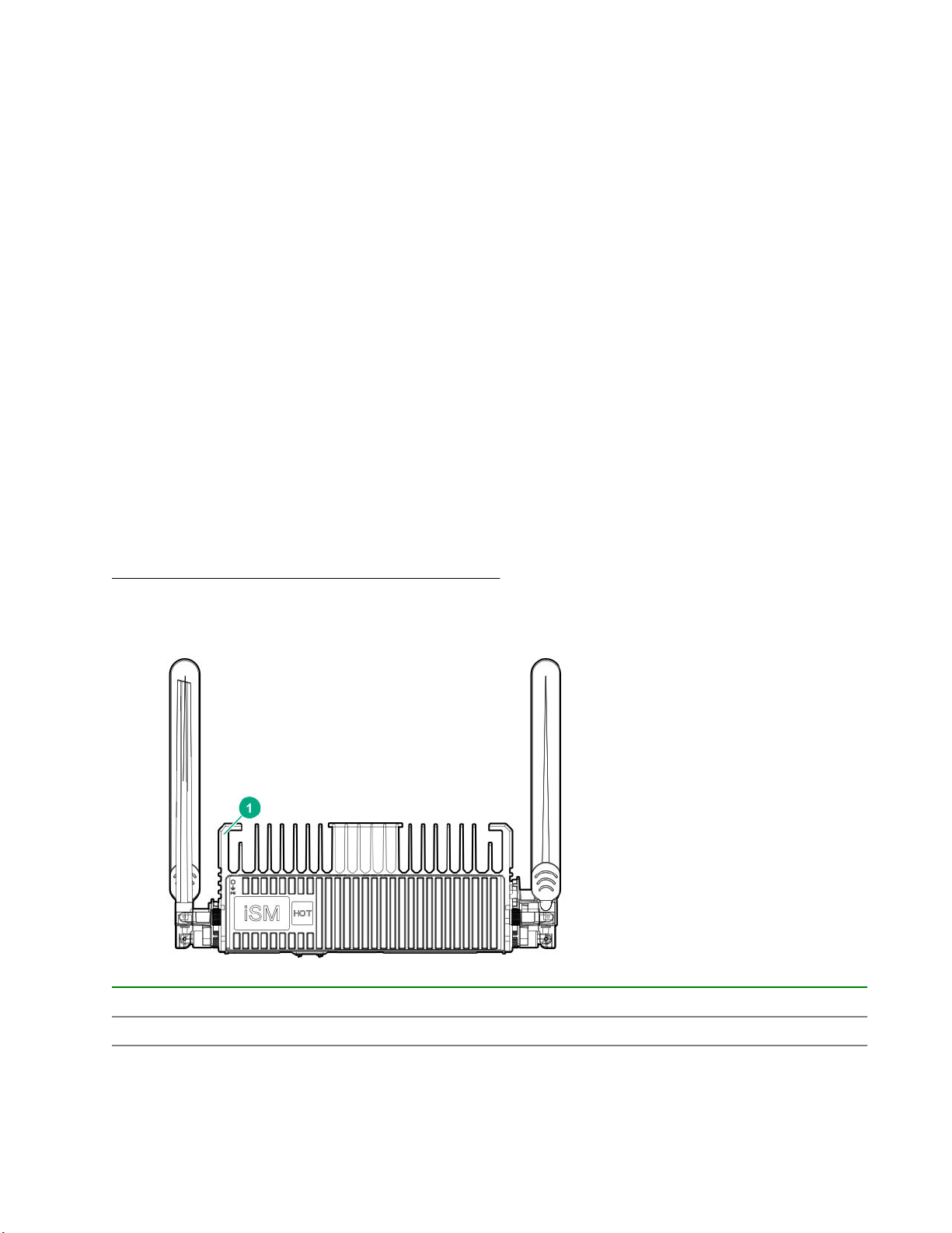
Front panel component
Item Description
1 Top cover
10 Components and site requirements
Page 11
Rear panel components
The is available in different configurations. Depending on the daughter card installed in the system, the rear
panel components for the system will change.
For rear panel component identification, see the following:
• Rear panel components when no daughter card is installed
• Rear panel components when 4 ports 1GBE Ethernet with TSN support daughter card is installed
• Rear panel components when 2 ports RS232/422/485 opto Isolated daughter card is installed
• Rear panel components when 2 ports CAN Bus A/B/FD 2.0 opto isolated daughter card is installed
• Rear panel components when 8 Bits Configurable GPIO daughter card is installed
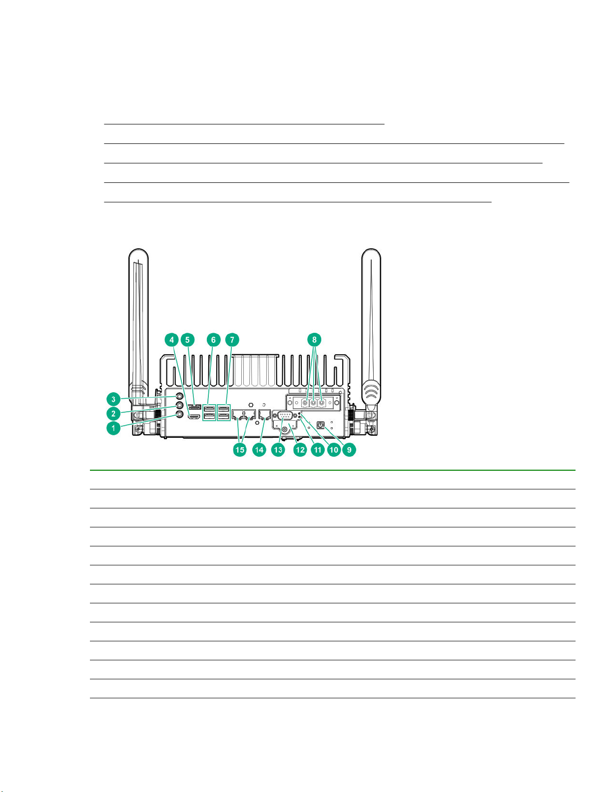
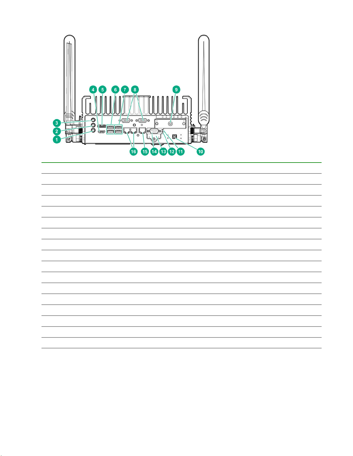
No daughter card configuration
Item Description
1 Mic
2 Line out
3 Line in
4 HDMI port
5 Display port
6 USB 3.0 ports
7 USB 2.0 ports
8 Power connectors
9 Power on button
10 iSM Reset
11 CPU Reset
Table Continued
Components and site requirements 11
Page 12
Item Description
12 SD card slot
13 Serial port
14 RJ–45/iSM/LAN management port
15 RJ–45 ports
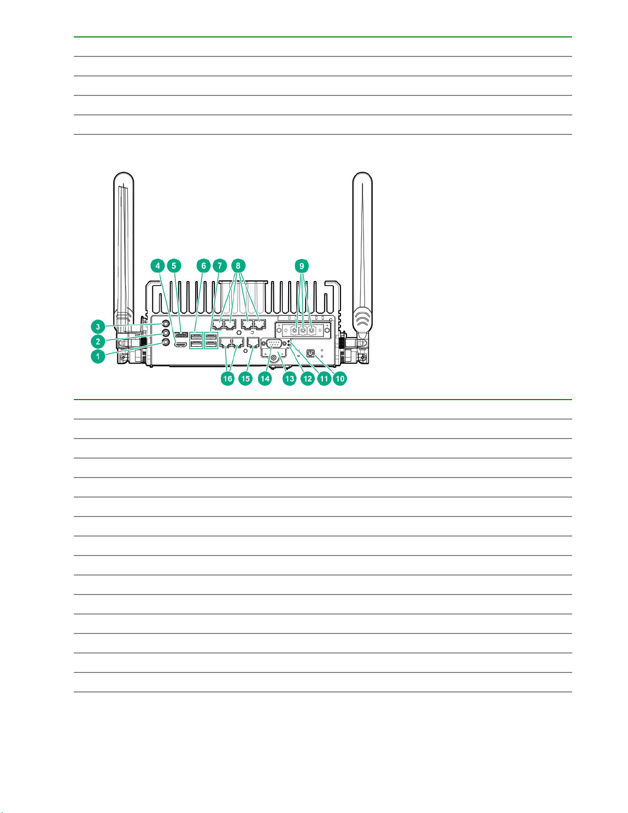
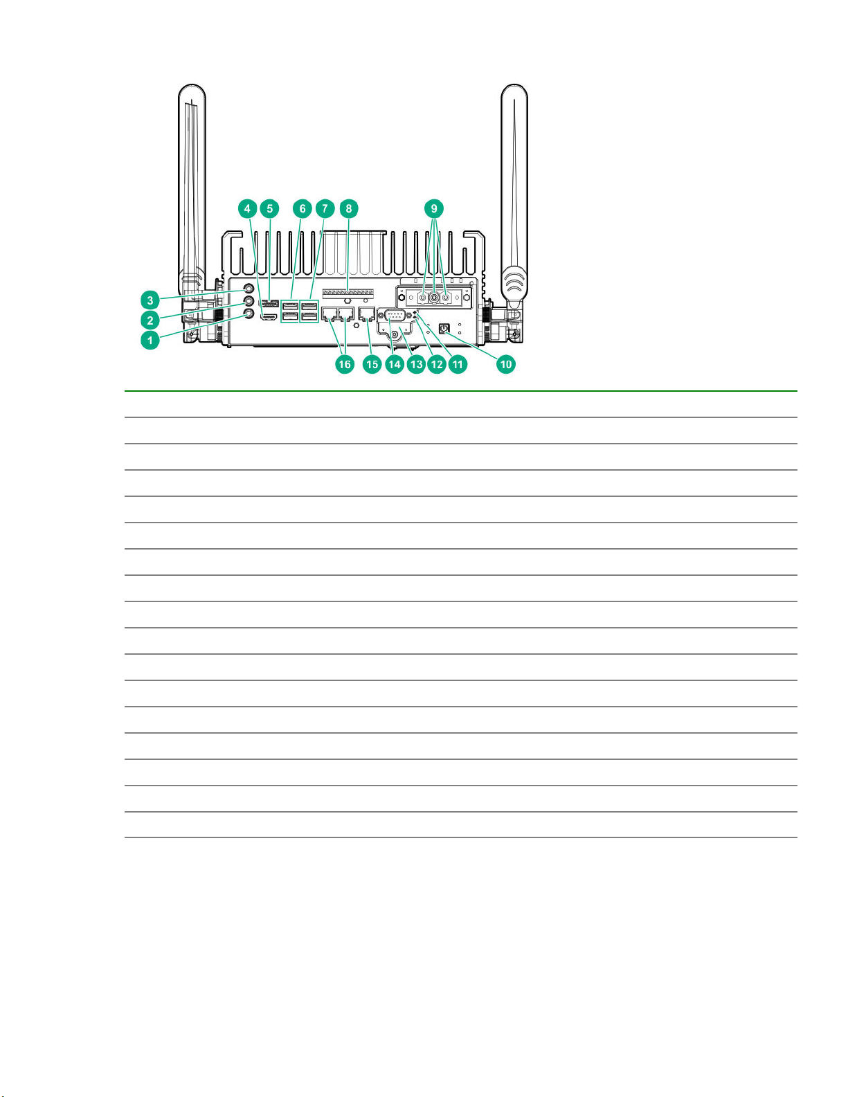
4 ports 1GBE Ethernet with TSN support daughter card configuration
Item Description
1 Mic
2 Line out
3 Line in
4 HDMI port
5 Display port
6 USB 3.0 ports
7 USB 2.0 ports
8 TSN daughter card ports
9 Power connectors
10 Power on button
11 iSM Reset
12 CPU Reset
13 SD card slot
14 Serial port
Table Continued
12 Components and site requirements
Page 13
Item Description
15 RJ–45/iSM/LAN management port
16 RJ–45 ports
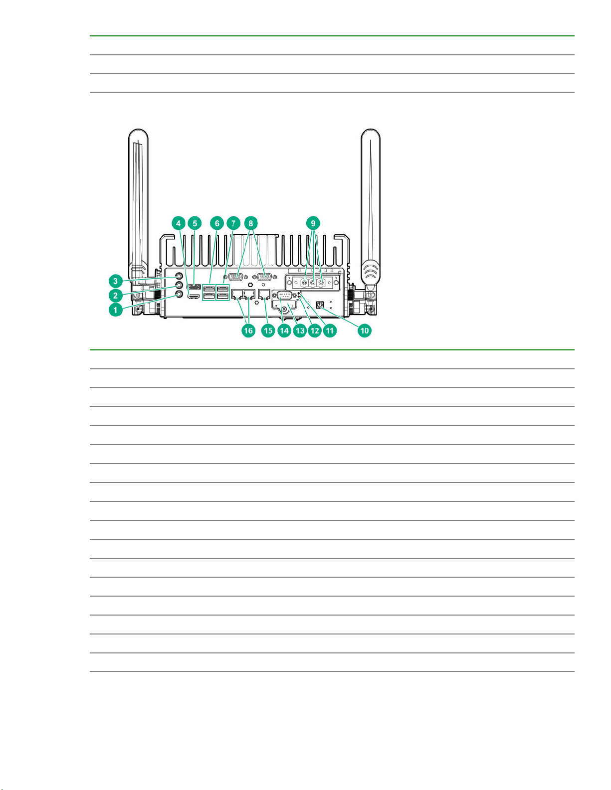
2 ports RS232/422/485 opto isolated daughter card configuration
Item Description
1 Mic
2 Line out
3 Line in
4 HDMI port
5 Display port
6 USB 3.0 ports
7 USB 2.0 ports
8 Serial daughter card ports
9 Power connectors
10 Power on button
11 iSM Reset
12 CPU Reset
13 SD card slot
14 Serial port
15 RJ–45/iSM/LAN management port
16 RJ–45 ports
Components and site requirements 13
Page 14
2 ports CAN Bus A/B/FD 2.0 opto isolated daughter card configuration
Item Description
1 Mic
2 Line out
3 Line in
4 HDMI port
5 Display port
6 USB 3.0 ports
7 USB 2.0 ports
8 CANBUS card ports
9 Power connectors
10 Power on button
11 iSM Reset
12 CPU Reset
13 SD card slot
14 Serial port
15 RJ–45/iSM/LAN management port
16 RJ–45 ports
14 Components and site requirements
Page 15
8 Bits Configurable GPIO daughter card configuration
Item Description
1 Mic
2 Line out
3 Line in
4 HDMI port
5 Display port
6 USB 3.0 ports
7 USB 2.0 ports
8 DIO daughter card port
9 Power connectors
10 Power on button
11 iSM Reset
12 CPU Reset
13 SD card slot
14 Serial port
15 RJ–45/iSM/LAN management port
16 RJ–45 ports
Components and site requirements 15
Page 16
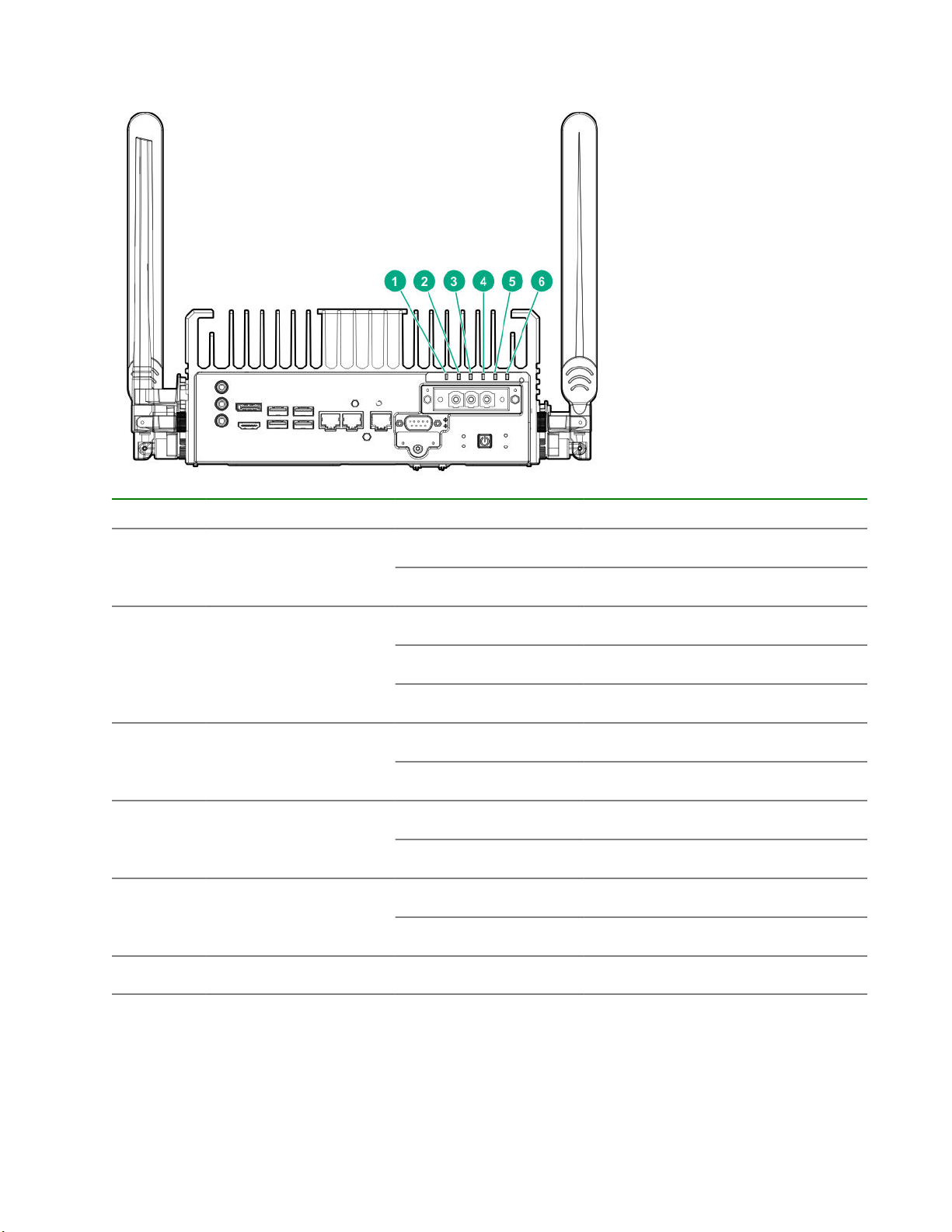
Rear panel LEDs
Item LED Status Definition
1
2
3
4
5
6
Power supply Solid green Normal operation
Amber Standby mode
Health Solid green Normal operation
Amber Degraded condition
Red Critical condition
UID Solid blue Activated
Flashing blue Active firmware update in progress
1
SSD1
Solid green Drive activity
Off No drive activity
2
SSD2
Solid green Drive activity
Off No drive activity
Wireless White Wireless network enabled
1
This LED indicates activity for M.2 SATA SSD that is installed under the top cover.
2
This LED indicates activity for PCIe NVMe SSD.
16 Components and site requirements
Page 17
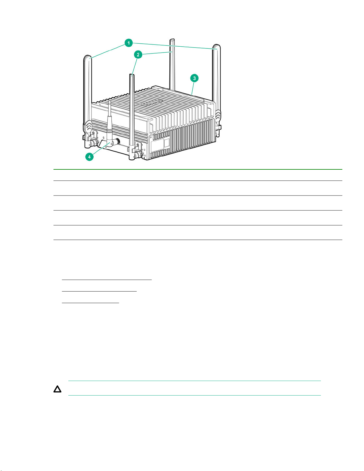
Antenna connector locations
Item Description
1
2
3
4
LTE antenna (optional)
WiFi antenna (optional
Antenna port
iSM antenna (Management)
System installation site requirements
Before installing the system, verify that the following site requirements are met:
•
Space and airflow requirements
• Temperature requirements
• Power requirements
HPE recommends that you install or position the system in a location with restricted access, where the access
is secured and controlled. The users/technicians handling the system should be informed about the
restrictions applied and precautions to be taken.
Space and airflow requirements
To allow for servicing and adequate airflow
, observe the following space and airflow requirements:
Leave a minimum 20 cm (7.9 in) clearance space at the top, bottom, and front of the system.
CAUTION: To prevent improper cooling and damage to the equipment, do not cover the system.
Components and site requirements 17
Page 18

Temperature requirements
To ensure continued safe and reliable equipment operation, install or position the system in a well-ventilated,
climate-controlled environment.
Configuration T
EL 300 System -30°C to 70°C (158°F) Operating temperature
Power requirements
Installation of this equipment must comply with local and regional electrical regulations governing the
installation of information technology equipment by licensed electricians. This equipment is designed to
operate in installations covered by NFPA 70, 1999 Edition (National Electric Code) and NFP
for Protection of Electronic Computer/Data Processing Equipment). For electrical power ratings on options,
see the product rating label or the user documentation supplied with that option.
emperature
A-75, 1992 (code
18 Components and site requirements
Page 19
Hardware options installation
This chapter provides detailed instructions on how to install hardware options.
For more information on supported options, see the product QuickSpecs on the website at:
http://www.hpe.com/info/qs
To view the warranty for your server and supported options, see Warranty information on page 76.
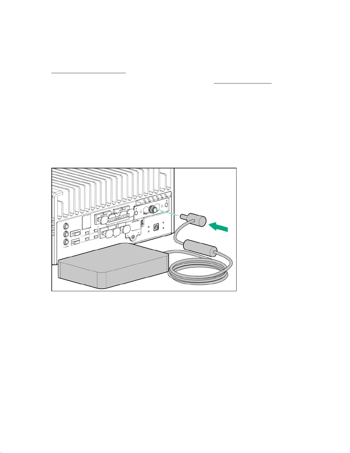
Power adapter option
The HPE Edgeline EL300 Converged Edge System supports the HPE EL300 80W 12 VDC power adapter
option. This option is supported only when the system is installed with the HPE EL300 12V DC Transfer
board.
Installing the power adapter option
Procedure
Connect the power adapter to the EL300 system.
The installation is complete.
SD card option kit
The system supports installation of an 8 GB SD card.
Installing the SD card option
Prerequisites
Before you perform this procedure, make sure that you have the T-10 screwdriver available.
Procedure
1. Remove the SD port cover from the rear panel of the system.
Hardware options installation 19
Page 20
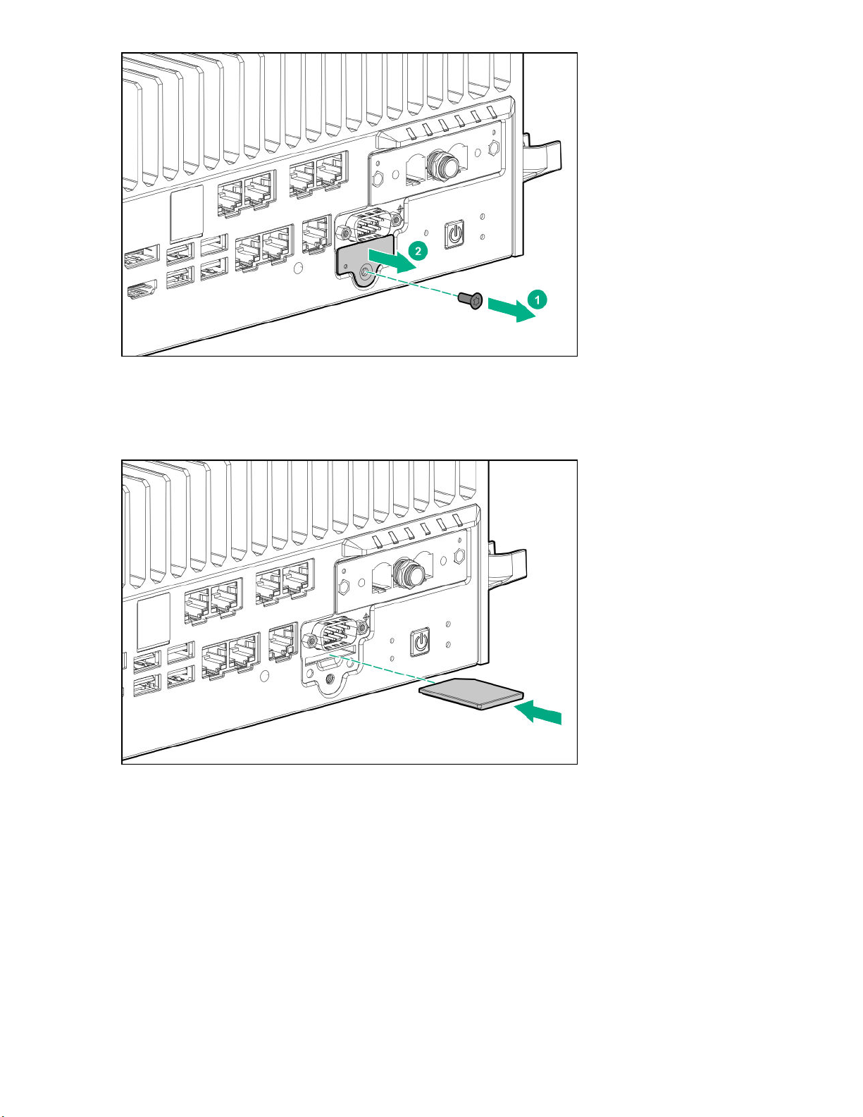
2. If installed, remove the serial port connector.
3. Insert the SD card in the slot.
Make sure to insert the card with the label side downwards.
4. If removed, install the serial port connector
5. Reinstall the SD port cover.
20 Hardware options installation
Page 21
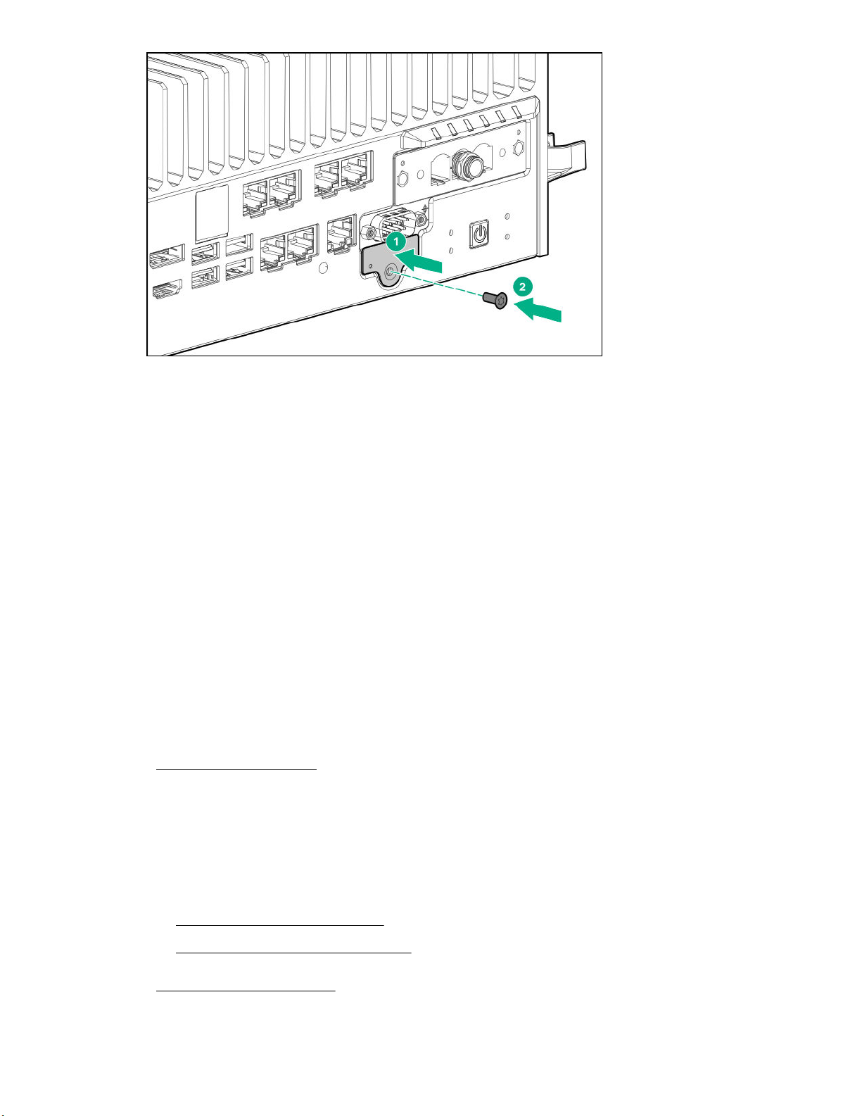
The installation is complete.
SFF to M.2 adapter option
The SFF to M.2 adapter option is required for installing an additional SAT
EL300 Converged Edge System.
Installing the SFF to M.2 adapter option
Prerequisites
Before you perform this procedure, make sure that you have the following items available:
-15 security screwdriver
• T
• Phillips screwdriver
• M.2 SSD module
• Hex nut screwdriver
Procedure
1. Power down the system.
2. Remove all power:
a. Disconnect the power cord from the power source.
b. Disconnect the power cord from the system.
A M.2 SSD in the HPE Edgeline
3. Depending on the surface the system is installed on, do one of the following:
a. Dismount the system from wall.
b. Dismount the system from the rails.
4. Remove the security cover.
Hardware options installation 21
Page 22
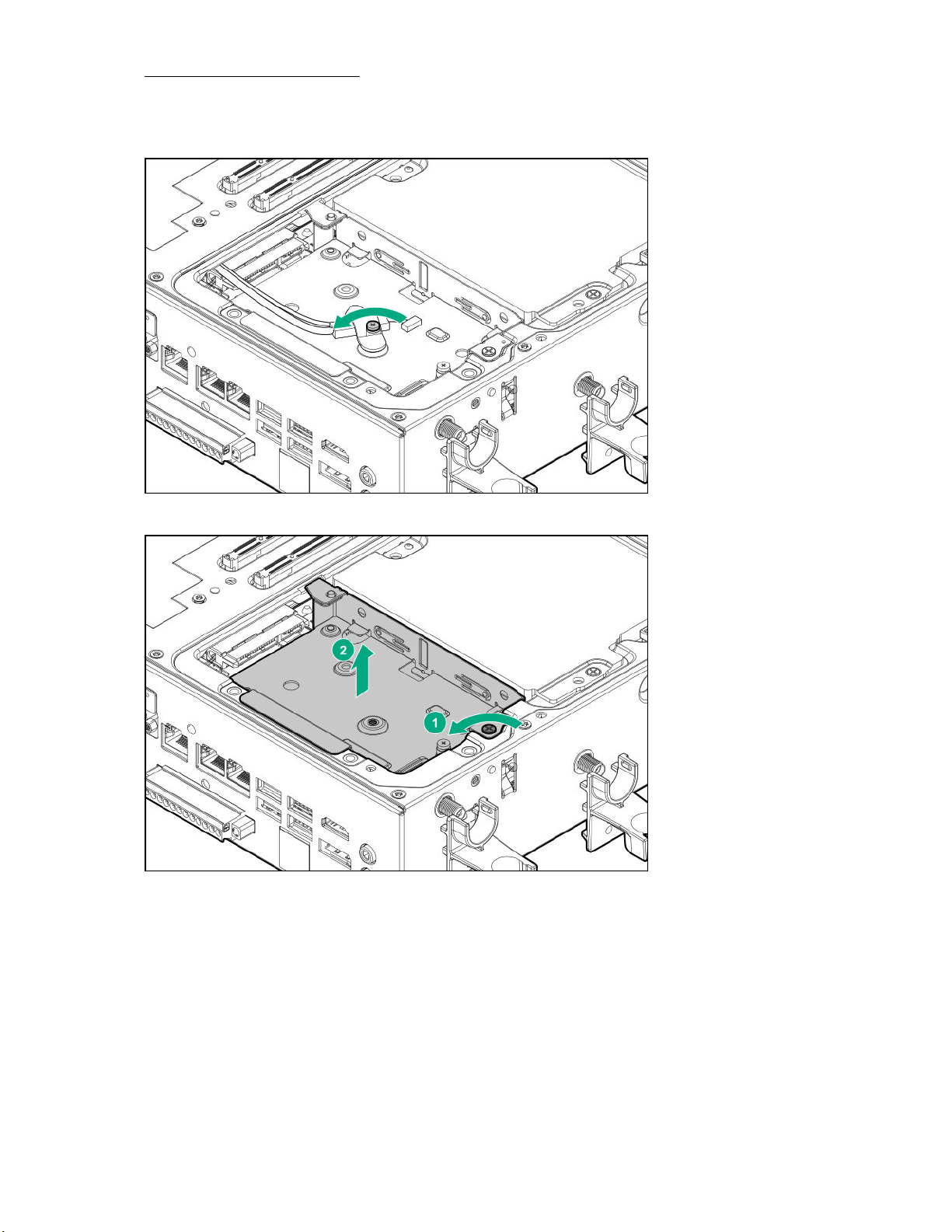
5. Remove the drive cage cover.
6. Remove the standoff (Hex nut) screw securing the SA
Retain the standoff (Hex nut) for installing the M.2 adapter board.
7. Remove the SFF drive cage.
TA cable and I2C cable.
8. Install the M.2 adapter board on the drive cage.
22 Hardware options installation
Page 23
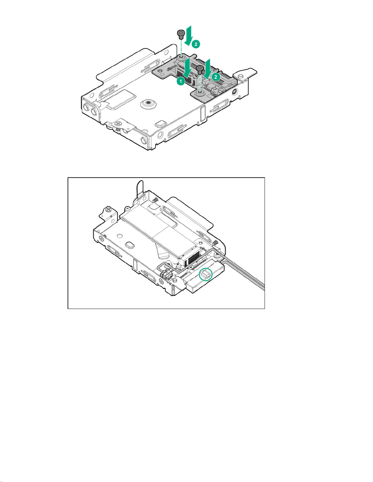
9. Connect the SAT
the connector is in upward direction.
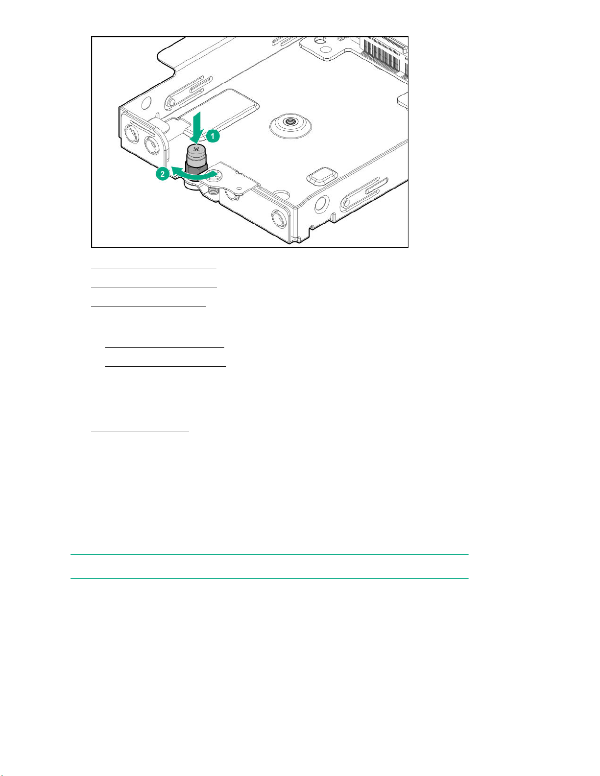
10. Install the stand off nut on the drive cage.
A cable and the I2C cable on the drive cage. Ensure that the I2C clip holder installed on
Hardware options installation 23
Page 24
11. Install the M.2 SSD module.
12. Install the drive cage cover.
13. Install the security cover.
14. Do one of the following:
• Mount the system on wall.
• Mount the system on rails.
15. Connect the power cord to the system.
16. Connect the power cord to the power source.
17. Power up the system.
The installation is complete.
M.2 SSD module option
The first M.2 SSD module is preinstalled in the HPE EL300 Edgeline Converged Edge System. Additional M.2
SAT
A SSD can be installed using the SFF to M.2 adapter.
Installing the M.2 SSD module
NOTE: The M.2 SSD installed on the drive cage does not have any activity LED associated.
Prerequisites
Before you perform this procedure, make sure that you have the following items available:
• M.2 SSD module
Hex nut screwdriver
•
24 Hardware options installation
Page 25
• T-15 security screwdriver
• Phillips screwdriver
Procedure
1. Power down the system.
2. Remove all power:
a. Disconnect the power cord from the power source.
b. Disconnect the power cord from the system.
3. Depending on the surface the system is installed on, do one of the following:
a. Dismount the system from wall.
b. Dismount the system from the rails.
4. Remove the security cover.
5. Remove the drive cage cover.
6. Install the M.2 adapter on the drive cage.
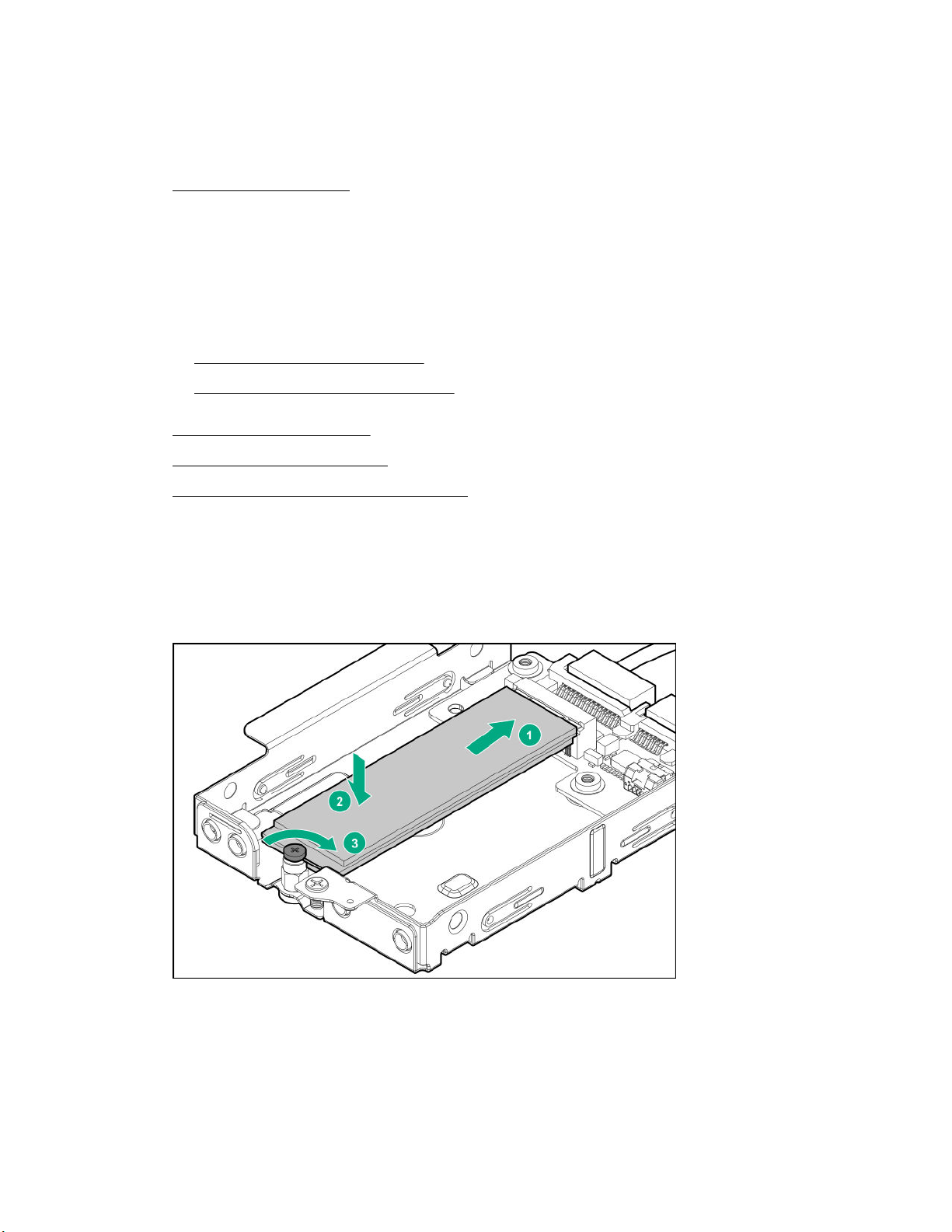
7. Install the M.2 SSD on the drive cage and secure it with the standoff screw:
a. Insert the SSD into the slot.
b. Press down the SSD in horizontal direction.
c. Install the SSD mounting screw to secure the SSD.
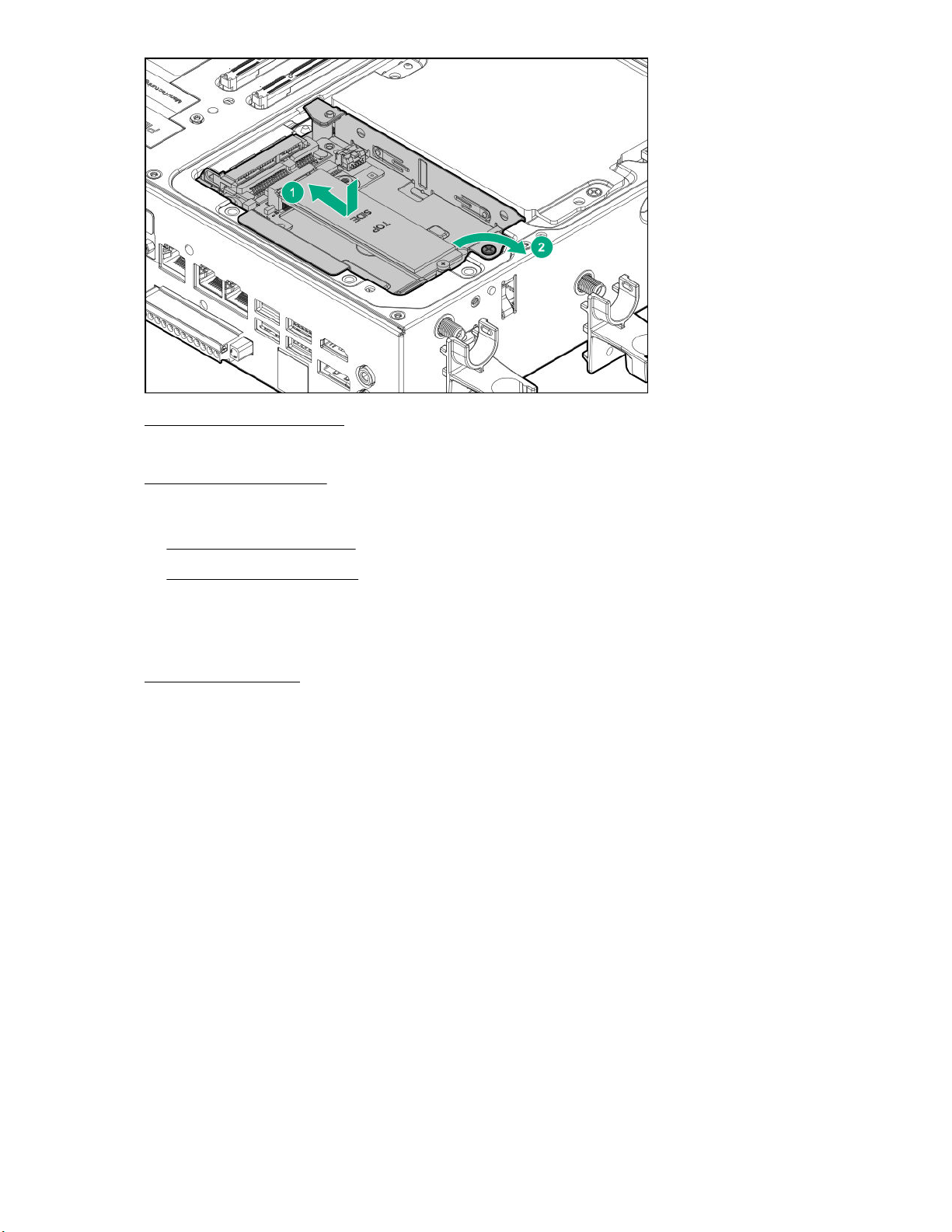
8. Install the drive cage:
a. Insert the drive cage in the slot.
b. Secure it with screw.
Hardware options installation 25
Page 26
9. Install the drive cage cover.
Make sure to remove the gap pad liner from the drive cage cover, before installing.
10. Install the security cover.
11. Do one of the following:
• Mount the system on wall.
• Mount the system on rails.
12. Connect the power cord to the system.
13. Connect the power cord to the power source.
14. Power up the system.
The installation is complete.
26 Hardware options installation
Page 27

Wireless network kit and antenna installation
The HPE Edgeline EL300 Converged Edge System supports remote management over wireless networks.
This allows the system to be deployed anywhere that is covered by WiFi or cellular signal.
Install the network cards first, then install the associated antennas. The system includes attachment points for
two types of antennas. Install one or both types depending on your configuration:
• HPE EL Network WiFi option kit
• HPE EL Network LTE option kit
HPE Edgeline WiFi/Bluetooth Intel AC9260 option kit
This option enables WiFi connectivity for the HPE Edgeline EL300 Converged Edge System. This option kit
comprises of WiFi network card and WiFi antennas.
Installing the WiFi card
Prerequisites
Before you perform this procedure, make sure that you have the following items available:
-15 security screwdriver
• T
• Phillips screwdriver
Procedure
1. Power down the system.
2. Remove all power:
a. Disconnect the power cord from the power source.
b. Disconnect the power cord from the system.
3. Depending on the surface the system is installed on, do one of the following:
a. Dismount the system from wall.
b. Dismount the system from the rails.
4. Remove the security cover.
5. Remove the drive cage cover.
6. Remove the heat spreader.
7. Remove the gap pad liner for the WiFi card from the heat spreader.
8. Install the WiFi card.
Wireless network kit and antenna installation 27
Page 28

9. Connect the WiFi antenna cables.
CAUTION: The connectors on the card are fragile, take utmost care when connecting the antenna
cables.
10. Install the heat spreader.
11. Install the drive cage cover.
12. Install the security cover.
13. Install the preferred bracket option.
14. Install the WiFi antennas.
15. Do one of the following:
28 Wireless network kit and antenna installation
Page 29

• Mount the system on wall.
• Mount the system on rails.
16. Connect the power cord to the system.
17. Connect the power cord to the power source.
18. Power up the system.
The installation is complete.
Installing the WiFi antennas
Prerequisites
Before you perform this procedure:
• Make sure that the bracket option is installed on the HPE Edgeline EL300 system.
.
• Make sure that you have the T
Procedure
1. Locate the correct antenna slot.
-15 security screwdriver available.
2. Install the antenna.
The antenna shown in the image might be different from your system.
Wireless network kit and antenna installation 29
Page 30

3. Install the antenna holders.
HPE Edgeline Wireless WAN 4G/LTE EM7565 Wide Temperature option kit
The HPE Edgeline EL300 Converged Edge System is designed to operate in remote or isolated locations.
When installed in such environments, the L
This option enables 4G/LTE network connectivity for the HPE Edgeline EL300 system. The HPE Edgeline
Wireless WAN 4G/LTE EM7565 Wide Temperature option kit comprises of LTE network card and LTE
antennas.
Installing the LTE network card
Prerequisites
Before you perform this procedure, make sure that you have the following items available:
•
-15 security screwdriver
T
• Phillips screwdriver
30 Wireless network kit and antenna installation
TE module supports remote management of the EL300 system.
Page 31

Procedure
1. Power down the system.
2. Remove all power:
a. Disconnect the power cord from the power source.
b. Disconnect the power cord from the system.
3. Depending on the surface the system is installed on, do one of the following:
a. Dismount the system from wall.
b. Dismount the system from the rails.
4. Remove the security cover.
5. Remove the drive cage cover.
6. Remove the heat spreader.
7. Install the LTE card.
8. Connect the LTE antenna cables.
CAUTION: The connectors on the card are fragile, take utmost care when connecting the antenna
cables.
Wireless network kit and antenna installation 31
Page 32

9. Optional: Install the SIM card.
10. Remove the LTE gap pad liner from the heat spreader
11.
Install the heat spreader.
12. Install the drive cage cover.
13. Install the security cover.
14. Install the preferred bracket option.
15. Install the LTE antennas.
16. Do one of the following:
• Mount the system on wall.
• Mount the system on rails.
17. Connect the power cord to the system.
18. Connect the power cord to the power source.
19. Power up the system.
The installation is complete.
Installing the SIM card
.
IMPORTANT: The SIM cards are supplied by your preferred mobile broadband provider, and cannot be
ordered from HPE. The SIM cards must be nano-SIM form factor
The EL300 system supports installation of two SIM cards. The first SIM card must be installed in the primary
slot location only.
32 Wireless network kit and antenna installation
.
Page 33

Item Description
1 Secondary slot
2 Primary slot
Prerequisites
Before performing this procedure:
Make sure that the LTE network card is installed.
Procedure
1. Install the SIM card in primary slot location.
2. Optional: Install a secondary SIM card.
3. Install the heat spreader.
Make sure to remove the gap pad liner from the heat spreader.
Wireless network kit and antenna installation 33
Page 34

4. Install the drive cage cover.
5. Install the security cover.
6. Install the LTE antennas.
7. Do one of the following:
• Mount the system on wall.
• Mount the system on rails.
8. Connect the power cord to the system.
9. Connect the power cord to the power source.
10. Power up the system.
Installing the LTE antennas
Prerequisites
Before you perform this procedure:
• Make sure that the bracket option is installed on the HPE Edgeline EL300 system.
.
• Make sure that you have the T
Procedure
1. Locate the correct antenna slot.
-15 security screwdriver available.
2. Install the antenna.
The antenna shown in the image might be different from your system.
34 Wireless network kit and antenna installation
Page 35

3. Install the antenna holders.
Wireless network kit and antenna installation 35
Page 36

System mount options
The HPE Edgeline EL300 Converged Edge System requires to be mounted on a vertical surface. There are
two mounting options available for the system:
• Wall mounting option
• DIN rail mounting option
The EL300 system also supports bracket options that assist in the mounting of the system.
This chapter provides instructions for mounting the HPE Edgeline EL300 Converged Edge System.
Bracket option kits
The EL300 system supports two bracket option kits:
• Base only bracket option
• Standard bracket option
Depending on the hardware configuration selected, any one of the bracket options can be installed on the
HPE Edgeline EL300 Converged Edge System.
Base only bracket option kit
The base only bracket option offers installation support for the EL300 base system only
does not support expansion unit installation.
The following components are available with the option kit:
• Base bracket panels (2)
• T-15 screws
• Cable management bracket
• Reusable cable ties and Velcro
Installing the base only bracket option
Prerequisites
Before you perform this procedure, make sure that you have the T-15 security screwdriver available.
Procedure
1. Place the system on a flat level surface.
2. Attach the brackets on the system:
a. Place the brackets on the side of the system.
. This bracket option
b. Secure the brackets with T-15 screws.
36 System mount options
Page 37

3. Install the cable management bracket.
The installation is complete.
Standard bracket option kit
The HPE Edgeline EL300 Converged Edge System can be connected to additional expansion units for
increased functionality and connectivity options. The standard bracket option is installed when additional
expansion board support is required.
The standard bracket option can be installed to support the following hardware configurations:
• HPE Edgeline EL300 base unit
•
HPE Edgeline EL300 base unit + 1 expansion unit
• HPE Edgeline EL300 base unit + 2 expansion units
The following components are available with the option kit:
• Standard bracket panels (2)
• T-15 screws
• Bracket handles
• Cable management bracket
• Reusable cable ties and velcro
System mount options 37
Page 38

Installing the standard bracket option
Prerequisites
Before you perform this procedure, make sure that you have the T-15 security screwdriver available.
Procedure
1. Attach the bracket handles to the bracket panels.
2. Place the system on a flat level surface.
3. Attach the brackets on the system:
a. Place the brackets on the side of the system.
b. Secure the brackets with T-15 screws.
4. Install the cable management bracket.
38 System mount options
Page 39

The installation is complete.
Wall mounting option kit
The wall mounting option kit is required when mounting the system on a wall.
Installing the wall mounting kit
Prerequisites
Before you perform this procedure:
• Make sure that the preferred bracket option is installed on the HPE Edgeline EL300 system.
• Make sure that you have the following items available:
Combo screws and wall anchors
◦
◦ Phillips screwdriver
◦ Drilling machine
◦ 5/6 inch drill bit
Procedure
1. For hollow wall - Install the wall mounting base panel:
a. Identify the location for installing the mounting panel.
b. Place the wall mount base panel on the selected position on the wall and mark the screw locations.
NOTE:
c. Drill pilot holes on the marked screw locations and install the wall anchors.
Wall anchors are not required for holes aligned on the internal wall stud.
d. Install the top two screws halfway and hang the base panel.
e. Secure the base panel by tightening all the screws.
Align minimum one column, out of the three middle panels, to the internal wall stud.
System mount options 39
Page 40

2. For brick and concrete wall - Install the wall mounting base panel:
a. Identify the location for installing the mounting panel.
b. Place the wall mount base panel on the selected location one the wall and mark the position of all the
screw mounting holes.
c. Drill pilot holes on the marked screw locations and install the wall anchors.
d. Install the top two screws halfway and hang the wall mount
e. Secure the base panel by tightening all the screws.
3. Install the system on the wall mount base panel:
a. Align the system mounted on brackets with the spools of the base panel.
b. Secure the system with screws.
40 System mount options
Page 41

The installation is complete.
DIN rail mounting panel option kit
The DIN rail mounting panel option is required when mounting the system on a DIN rail.
Installing the rail mounting kit
Prerequisites
Before you perform this procedure:
• Make sure that the preferred bracket option is installed on the HPE Edgeline EL300 system.
• Make sure that you have the T
Procedure
1. Attach the DIN rail clips to the DIN mounting panel:
a. Align the rail clips to the DIN panel.
b. Install the screws.
For two-rail option loosely install the clips for the lower rail.
• Single rail
-15 security screwdriver available.
System mount options 41
Page 42

• Dual rails
2. Install the mounting panel on the rails:
a. Slide up the base of the rail clip.
b. Install the bottom screw.
When installing two rails, the distance between the rails should be 178.8mm.
Single rail
•
42 System mount options
Page 43

• Dual rails
3. Secure the rails installed by tightening the screws on the rail clips.
• Single rail
System mount options 43
Page 44

• Dual rails
4. Install the system on the rail-mounted panel:
a. Align the system mounted on brackets with the spools of the base panel.
b. Secure the system with screws.
44 System mount options
Page 45

The installation is complete.
System mount options 45
Page 46

Associated hardware procedures
This chapter describes the hardware operations carried out prior to and after installing or removing a
hardware option, or performing system maintenance or troubleshooting.
Before performing these hardware operations, review and observe system warnings and cautions.
Installing the power supply
Procedure
1. Connect the power cord to the power connector at the rear of the system.
2. Power up the system.
Powering up the system
If the system is connected to a power source, it powers up automatically. It needs to be powered up only after
a manual shutdown or after autopower of
To power up the system, press the Power On/Standby button.
Powering down the system
f.
Before powering down the
system data and programs.
Use one of the following methods to power down the
• Press and release the Power On/Standby button.
This method initiates a controlled shutdown of applications and the OS before the system enters standby
mode.
• Press and hold the Power On/Standby button for more than 4 seconds to force the system to power down.
This method forces the system to power down without properly exiting applications and the OS. If an
application stops responding, you can use this method to force a shutdown.
Before proceeding, you must ensure that the system is in standby mode by verifying that the system power
LED is off.
system for any upgrade or maintenance procedures, you must back up critical
Mounting the system
The following kits are available to mount your system:
• Wall mounting kit
• Rail mounting kit
Before mounting the system, make sure that you do the following:
system:
• Read the site requirements for the
System installation site requirements on page 17
• Read the safety and compliance information on the
http://www.hpe.com/support/safety-compliance-enterpriseproducts
46 Associated hardware procedures
system:
HPE website:
Page 47

Dismounting the system
Depending on the selected mounting option:
• Dismount the system from a wall mount
• Dismount the system from a rail mount
Dismount the system from a wall mount panel
Prerequisites
Before you perform this procedure, make sure that you have the T-15 security screwdriver available.
Procedure
1. Power down the system.
2. Disconnect all cables connected to the system.
3. Remove the system from the wall mounting panel.
Dismount the system from a rail mount panel
Prerequisites
Before you perform this procedure, make sure that you have the T-15 security screwdriver available.
Procedure
1. Power down the system.
2. Disconnect all cables connected to the system.
3. Remove the system from the rail-mounted base panel.
Associated hardware procedures 47
Page 48

Removing the antenna
Procedure
1. Power down the system.
2. Remove all power :
a. Disconnect the power cord from the power source.
b. Disconnect the power cord from the system.
3. Depending on the surface the system is installed on, do one of the following:
a. Dismount the system from wall.
b. Dismount the system from the rails.
4. Place the system on a flat, level surface.
5. Locate the correct antenna slot.
6. Remove the antenna.
The antenna shown in the image may be different from your system.
48 Associated hardware procedures
Page 49

Removing the brackets
Prerequisites
Before performing this procedure, make sure that you have the T-15 security screwdriver available.
Procedure
1. Power down the system.
2. Remove all power:
a. Disconnect the power cord from the power source.
b. Disconnect the power cord from the system.
3. Depending on the surface the system is installed on, do one of the following:
a. Dismount the system from wall.
b. Dismount the system from the rails.
4. Remove all the cables routed through the cable management bracket.
5. Place the system on a flat, level surface.
6. Remove the cable management arm.
Associated hardware procedures 49
Page 50

7. Remove the installed bracket panels:
• Base only bracket
• Standard bracket
Removing the security cover
Prerequisites
Before you perform this procedure, make sure that you have the following items available:
50 Associated hardware procedures
Page 51

• T-15 security screwdriver
• Phillips screwdriver
Procedure
1. Power down the system.
2. Remove all power:
a. Disconnect the power cord from the power source.
b. Disconnect the power cord from the system.
3. Depending on the surface the system is installed on, do one of the following:
a. Dismount the system from wall.
b. Dismount the system from the rails.
4. Place the server on a flat, level surface with the top cover facing down.
5. Remove the antennas on the system.
6. Remove the installed bracket option.
7. Remove the security cover:
a. Remove the screws securing the security cover.
b. Detach the pins of the security cover from the system, and then remove the security cover.
Installing the security cover
Prerequisites
Before you perform this procedure, make sure that you have the Phillips screwdriver available.
Associated hardware procedures 51
Page 52

Procedure
1. Install the security cover:
a. Align the pins on the security cover with the openings on the system.
b. Install the screws on the security cover and secure it to the system.
2. Install the preferred bracket option.
3. Install the antennas.
4. Do one of the following:
• Mount the system on wall.
• Mount the system on rails.
5. Connect the power cord to the system.
52 Associated hardware procedures
Page 53

6. Connect the power cord to the power source.
7. Power up the system.
Removing the drive cage cover
Prerequisites
Before you perform this procedure, make sure that you have the following items available:
-15 security screwdriver
• T
• Phillips screwdriver
Procedure
1. Power down the system.
2. Remove all power:
a. Disconnect the power cord from the power source.
b. Disconnect the power cord from the system.
3. Depending on the surface the system is installed on, do one of the following:
a. Dismount the system from wall.
b. Dismount the system from the rails.
4. Place the system on a flat, level surface with the top cover facing down.
5. Remove the antennas on the system.
6. Remove the installed bracket option.
7. Remove the security cover.
8. Remove the drive cage cover using the Philips screwdriver.
Associated hardware procedures 53
Page 54

Installing the drive cage cover
Prerequisites
Before you perform this procedure, make sure that you have the Phillips screwdriver available.
Procedure
1. Install the drive cage cover, using the Phillips screwdriver
2. Install the security cover
3. Install the preferred bracket option.
4. Install the antennas.
.
5. Do one of the following:
• Mount the system on wall.
• Mount the system on rails.
6. Connect the power cord to the system.
7. Connect the power cord to the power source.
8. Power up the system.
Removing the heatspreader
Prerequisites
Before you perform this procedure, make sure that you have the following items available:
-15 security screwdriver
• T
• Phillips screwdriver
54 Associated hardware procedures
Page 55

Procedure
1. Power down the system.
2. Remove all power:
a. Disconnect the power cord from the power source.
b. Disconnect the power cord from the system.
3. Depending on the surface the system is installed on, do one of the following:
a. Dismount the system from wall.
b. Dismount the system from the rails.
4. Remove the antennas on the system.
5. Remove the installed bracket option.
6. Remove the security cover.
7. Remove the drive cage cover.
8. Remove the heat spreader.
Installing the heatspreader
Prerequisites
Before you perform this procedure, make sure that you have the following items available:
-15 security screwdriver
• T
• Phillips screwdriver
Procedure
1. Install the heat spreader.
Associated hardware procedures 55
Page 56

2. Install the drive cage cover.
3. Install the security cover
4. Install the preferred bracket option.
5. Install the antennas
6. Do one of the following:
• Mount the system on wall.
• Mount the system on rails.
7. Connect the power cord to the system.
8. Connect the power cord to the power source.
9. Power up the system.
56 Associated hardware procedures
Page 57

Configuration
Quick task: Be prepared
“What do I need to know before I start configuring my
HPE EL300?”
TIP: Gather all the materials and information
you need before getting started, and double
check that your chosen OS is compatible with
your HPE EL300.
Decide on the type
of media from
which to install your
OS and prepare it.
Prepare for configuration
Prepare to configure your new system by completing the tasks below.
1.
Verify operating system support
For information about supported operating systems, see the Supported Operating Systems for Edgeline,
Moonshot, and IoT Gateway Systems at
2. Gather operating system installation media and product key (Windows, Linux)
Operating system installation can be performed using a network share (PXE boot), USB, SD card, or
virtual media. Be sure to have installation keys for operating systems that require them, and read any
implementation notices that accompany the OS. For portable media, the drive must have enough space to
store a complete OS image, with enough space left over for OS reporting files. HPE recommends that
portable media have a minimum of 32GB of space before storing installation images.
NOTE:
An iSM Advanced license is required to use virtual media.
Make sure you can
get an Internet
connection and a
business network
connection.
www.hpe.com/support/edgeline-moonshot-IoT-OS.pdf.
Not using DHCP? Plan your network
addressing scheme before starting to
configure the system.
3. Verify network connectivity
Ensure that the network connection is active, if needed.
erify Internet connectivity
4. V
Verify Internet access from your business network. Make a note of the gateway IP address, you may need
it later.
5. Plan for the network address
If you do not have DHCP enabled on the network, you must have networking details ready: An IP address
to assign, subnet mask, gateway address, and DNS name. For initial setup, it is faster to allow automatic
assignment of these details by connecting your system to a DHCP enabled network.
Connecting to HPE iSM the first time
HPE Edgeline Integrated System Manager (iSM) is a remote management tool embedded in the HPE
Edgeline EL300 Converged Edge System. iSM allows system administrators to remotely configure, update,
Configuration 57
Page 58

and monitor system health and activity. The embedded iSM management module has its own network
connection and IP address to which administrators connect on their dedicated management network, even
when the system is powered down. Depending on hardware configuration, Edgeline systems with iSM can be
connected to a management network using Ethernet or a wireless Wi-Fi, 3G, 4G, or LTE connection. iSM
fers a Web-based console (iSM GUI), a command line interface (iSM CLI), and is accessible using the
of
REST API.
Once the system is unboxed, connected to your management network, and powered up, there are a few
options for accessing iSM the first time. You can initially configure iSM by:
• Connecting to the iSM web interface using the WiFI access point (WiFi AP).
• Connecting to the iSM web interface through the management network.
• Connecting to the iSM CLI using a DB9 null modem serial cable and retrieving the DHCP assigned IP
address.
Connecting to the iSM web interface using the WiFi Access Point
HPE recommends this method for initial configuration.
Prerequisites
• System hardware unboxed and powered up, and WiFi antenna connected
Username and password noted from the chassis tag
•
• WiFi-enabled laptop or mobile device
Procedure
1. Search for available WiFi connections on your device.
The WiFi SSID starts with iSM, following by a dash, and up to 12 letters and numbers. For example,
iSM-813d2g5144fd.
2. Select the WiFi connection and then enter the password.
3. Open a browser window to 192.168.0.1.
The login page for iSM is displayed. Log in with the credentials printed on the chassis tag.
Connecting to the iSM web interface using Ethernet
When your setup devices are not WiFi-enabled, acquire the IP address through your management network.
Prerequisites
• System hardware unboxed and powered up
Username and password noted from the chassis tag
•
• Ethernet cable
• DHCP enabled management network
58 Configuration
Page 59

Procedure
1. Connect an Ethernet cable between the MGMT port on the system chassis and your management
network.
2. Wait for the hostname of your new system to propagate onto your network through DDNS and have an IP
address assigned through DHCP
Once propagated, acquire the IP address of the new system using standard network administrator tools
such as ICMP ping.
3. Access the iSM web interface by entering the IP address in a browser window on a separate computer.
Log in with the default credentials listed on the system chassis tag.
4. Optional: Some management networks disable ICMP ping or other tools administrators might use to find
the IP address. In the absence of these normal tools, use a null modem serial cable and serial session to
retrieve the IP address.
.
Connecting to the iSM CLI in a serial session
If ICMP ping or other tools are disabled on your management network, retrieve the IP address in a serial
session.
Prerequisites
• System hardware unboxed and powered up
Username and password noted from the chassis tag
•
• Null modem serial cable
• DHCP enabled management network
Procedure
1. Connect a null modem serial cable to the serial port on the system. Connect the other end to the system
you are using to configure.
NOTE: If your system was shipped with an HPE Edgeline Dual Serial Port daughter card, do not use serial
daughter ports for initial configuration of the system.
2. Start a terminal SSH session using a standard SSH tool like PuTTY. Use the following settings:
Specification V
Baud rate 115200
Data bits 8
Parity None
Stop bit 1 (8 N1)
Flow control XON/XOFF
alue
3. Log in by entering the default credentials shown on the chassis tag at the prompt.
4. Enter the relevant commands for showing or setting the network configuration.
Configuration 59
Page 60

iSM web interface
Use the iSM web interface to manage your HPE ProLiant EL300. Y
Browser requirements
The iSM
• JavaScript—The iSM web interface uses client-side JavaScript extensively.
• Cookies—Cookies must be enabled for certain features to function correctly.
• Pop-up windows—Pop-up windows must be enabled for certain features to function correctly. Verify that
• TLS—To access the iSM web interface, you must enable TLS 1.0 or later in your browser.
Supported browsers
iSM
• Microsoft Edge
• Mozilla Firefox
• Google Chrome mobile and desktop
web interface requires a browser that meets the following requirements:
This setting is not enabled by default in all versions of Internet Explorer. To check or change this setting,
see
Configuring the Internet Explorer JavaScript setting on page
pop-up blockers are disabled.
supports the latest versions of the following browsers:
ou can also use the iSM CLI.
60.
• Microsoft Internet Explorer 11
Configuring the Internet Explorer JavaScript setting
Some versions of Internet Explorer have JavaScript disabled by default. Use the following procedure to
enable JavaScript.
Procedure
1. Start Internet Explorer.
2. Select
3. Click Security.
4. Click Custom level.
5. In the Scripting section, set Active scripting to Enable.
6. Click OK.
7. Refresh your browser window.
Tools > Internet options.
Logging in to the iSM web interface
Procedure
1. Enter https://<iSM host name or IP address>
60 Configuration
Page 61

When you access the iSM web interface, you must use HTTPS (HTTP exchanged over an SSL encrypted
session).
The iSM login page opens. If a login security banner is configured, the banner text is displayed above the
login section.
2. Enter a local account Username and Password
TIP: When logging in to the iSM web interface for the first time:
• The default username is iot
• The default password is printed on the label attached to the chassis.
. The username is case sensitive.
About the iSM web interface controls
The left pane of the iSM web interface can be hidden from view at any time. Hiding the left pane gives more
space for the main pages to be displayed, but hides the navigation tree.
T
o hide the left pane, click X or click
•
o show the left pane, click
• T
Logout, lock, and help
There are three icons shown at the bottom of the left pane when the pane is open:
•
—This icon shows the currently logged-in username and a Logout option. Clicking Logout closes
your web interface session and returns to the login screen.
.
, and then click Log In.
.
•
• —This icon displays the online help for the iSM web interface.
Confirmation, status, and error messages
Some pages of the iSM
an Apply button. Confirmation, status and error messages display at the top of the page, so remember to
scroll back up to the top of the page after clicking Apply.
—This icon locks iSM and prevents configuration changes in the web interface. Clicking the icon
opens a confirmation dialog. Click Lock System or No, Go Back. Y
second time.
IMPORTANT: A license that supports this feature must be installed.
web interface require you to scroll down to see all the options available, or to reach
ou are asked to verify your choice a
Configuration 61
Page 62

Quick task: Configure the network connection and install an operating system
TIP: Verify your completed checklist!
Make sure you have everything from the
configuration preparation section of the
“I just purchased my first HPE EL300 system and
need to put it into production”
setup checklist before continuing.
Configure your
preferred network
connection and
settings in iSM.
Click here for detailed instructions.
Use iSM to update
the firmware.
Set the boot order to start from your
OS installation media and reboot the
host.
Complete the network configuration using Integrated System Manager and install an operating system
Complete the configuration by performing the following tasks.
The details for these tasks can be found in the HPE Integrated System Manager User Guide at
www.hpe.com/support/EL300-iSM-UG-en.
NOTE: iSM communicates with Remote Console over a private 16.x.x.x subnet. Do not connect the MGMT
port, and by extension iSM, to a subnet that has the same address space or network errors will occur.
1. Configure all iSM network connection settings that you intend to use on the Wired and W
pages:
• Enable and configure the WiFI access point on the WiFi AP page. This method of access can only be
used for initial setup.
• Configure a WiFi network connection on the WiFi page.
ireless Network
• Enable and configure cellular access on the LTE page.
• Configure the Host Name Settings on the General page.
• Choose and configure LAN addressing on the IPv4 or IPv6 pages.
Click here for detailed instructions about configuring network settings.
2. Update firmware or add files to the repository on the Firmware pages. Download firmware updates from
the HPE Support Center at http://www.hpe.com/support/hpesc.
Click here for detailed instructions about updating the firmware.
3. Store an operating system image on your chosen installation media. You can install an operating system
from a USB drive, virtual USB (virtual media), SD card, or PXE.
NOTE:
changing the host boot order. An iSM Advanced license is required to use virtual media and the remote
console. For detailed information about the iSM Advanced license, see the HPE Edgeline Converged Edge
System Licensing Guide at
62 Configuration
If you plan to use virtual media, mount the media before starting a remote console session or
http://www.hpe.com/support/EL-Converged-Edge-System-Licensing-en.
Page 63

4. Update the host boot order in BIOS, iSM GUI, or by using the iSM CLI so that the next reboot of the host
system checks your chosen installation media first.
NOTE: HPE recommends setting the boot order on the iSM GUI Boot Order page. Use remote console
(iSM Advanced license required) to update the boot order in BIOS, or connect a keyboard, monitor, and
mouse directly to the system. T
session to the IP address of iSM.
For the specific commands required to set boot order, see the HPE Integrated Service Manager User
Guide on the HPE Information Library at
Click here for detailed instructions about modifying the boot order.
5. Restart the host system and following the onscreen instructions to install the operating system.
Click here for detailed instructions about managing the system power.
o update the boot order using the iSM CLI, open an SSH command-line
http://www.hpe.com/info/EIL.
6. Immediately after installing the OS, unmount the virtual media and then move SAT
boot order (depending on where you installed the OS).
Click here for detailed instructions about modifying the boot order.
7. Register the product.
iSM Network Port-Network Summary
provides the following options for network connection:
iSM
To access the network settings, view or edit the network settings on the following pages:
•
Summary
• General
• IPv4
• IPv6
• WiFi
• WiFi AP
• LTE
A or NVMe to the top of
Viewing the network configuration summary
Procedure
Click Wired and W
The Summary tab is displayed.
Network configuration summary details
• Name—The name of the active iSM network interface.
• Host Name—The name assigned to the iSM subsystem. By default, the host name is iSM, followed by the
system serial number. This value is used for the network name and must be unique.
NOTE: You can configure the iSM host name on the General
ireless Network in the navigation tree.
page.
Configuration 63
Page 64

• MAC Address—The MAC address of the iSM network interface.
• Permanent MAC Address—The unchangeable MAC address of the iSM network interface.
• FQDN
• IPv6 Default Gateway— When IPv6 is enabled, the gateway is the default IP address iSM uses to access
• Speed (Mbps)—The speed of the wired network, measured in megabits per second.
• WiFi Network—The SSID of the WiFi network (if connected).
• Cellular Network—The broadband wireless provider.
— The fully qualified domain name of the system.
the network. When not enabled, this entry is blank.
IPv4 Summary details
• Address—The IPv4 address currently in use. If the value is 0.0.0.0, the IPv4 address is not configured.
• Address Origin—Indicates whether the address was supplied automatically by DHCP or is static.
• Gateway—The gateway address in use for the IPv4 protocol. If the value is 0.0.0.0, the gateway is not
configured.
• Subnet Mask—The subnet mask of the IPv4 address currently in use. If the value is 0.0.0.0, no
address is configured.
IPv6 Summary details
• Address—The IPv6 address currently in use. If the value is blank, the IPv6 address is not configured.
• Address State—Indicates whether the address was supplied automatically or is static.
• Gateway—The gateway address in use for the IPv6 protocol. If the value is blank, the gateway is not
configured.
• Prefix Length—The subnet mask of the IPv6 address currently in use.
• Link Local Address—The IPv6 address for the network segment.
• Link Local Gateway—The IPv6 address of the local network segment gateway. If the value is blank, the
gateway is not configured.
• Prefix Length—The subnet mask of the IPv6 link-local address.
IPv6 Address Policy table
This table shows whether IPv6 or IPv4 addresses are preferred.
WiFi Summary details
• SSID—The service set identifier which provides the name of the wireless network.
• Strength—A measure of how powerful the signal strength of the connection is to the WiFi network.
• Status—The status of the WiFi connection, connected or not connected.
• Security—The type of security in use on the WiFi connection.
64 Configuration
Page 65

LTE Summary details
• Enabled—Indicates whether LTE is enabled (True or False).
• APN—The access point name, which may or may not include an operator identifier.
• Status—Indicates the state of the connection.
Configuring iSM Host Name Settings
Use the iSM General page to configure the iSM Host Name and domain name. The host name and the
domain name together constitute the fully qualified domain name.
Procedure
1. Click Wired and W
2. Enter the iSM Subsystem Name (Host name).
The host name is the DNS name of the iSM subsystem. This name can be used only if DHCP and DNS
are configured to connect to the iSM subsystem name instead of the IP address.
3. Enter the iSM Domain Name if DHCP is not configured.
4. Click Apply.
ireless Network in the navigation tree, and then click the General tab.
iSM host name and domain name limitations
The Subsystem Name (Host name) is initially set at the factory, and is listed on the chassis tag. This default
host name is a combination of iSM
When reconfiguring the Host Name Settings, note the following:
• Name service limitations—The subsystem name is used as part of the DNS name.
◦ DNS allows alphanumeric characters and hyphens.
◦ Always start the hostname with a letter, and not with a number or a hyphen. Any combination of letters,
numbers, and the hyphen can be used after the first letter.
◦ Name service limitations also apply to the Domain Name.
• Namespace issues—To avoid these issues:
followed by the system serial number.
◦ Do not use the underscore character.
◦ Limit subsystem names to 15 characters.
◦ Verify that you can ping the iSM processor by IP address and by DNS name.
◦ Verify that NSLOOKUP resolves the iSM network address correctly and that no namespace conflicts
exist.
◦ Flush the DNS name if you make any namespace changes.
Configuring IPv4 settings
Prerequisites
Admin privilege
iSM
Configuration 65
Page 66

Procedure
1. Click Wired and W
2. Configure the DHCPv4 Configuration setting.
3. Configure the IPv4 Address Configuration settings.
4. Configure the DNS Configuration settings.
5. To save the changes you made on the IPv4 Settings page, click Apply.
6. When you are finished configuring the iSM network settings on the Wired and Wireless Network tabs,
restart the iSM system.
It might take several minutes before you can re-establish a connection.
ireless Network in the navigation tree, and then click the IPV4 tab.
DHCPv4 Configuration setting
The DHCPv4 setting is enabled by default.
Enable DHCPv4
Enables iSM to obtain an IP address (and other network specific address settings) from a DHCP server.
NOTE: When DHCPv4 is enabled, the IPv4 Address Configuration section and DNS Configuration
section are automatically assigned. When the system is rebooted, these automatic assignments might
change.
Static IPv4 Address Configuration settings
IPv4 Address
The iSM IP address. The IP address is supplied automatically when DHCP is enabled. When DHCP is not
enabled, enter a static IP address.
IPv4 Subnet Mask
The subnet mask of the IP network. The subnet mask is supplied automatically when DHCP is enabled.
When DHCP is not enabled, enter a subnet mask for the network.
IPv4 Gateway
The iSM gateway IP address. The iSM gateway IP address is supplied automatically when DHCP is
enabled. When DHCP is not enabled, enter an IP address for the gateway.
IPv4 DNS Configuration settings
Primary DNS Server
This value is supplied automatically when DHCP is enabled. If you are using a static IP address, no name
servers are used.
Secondary DNS Server
This value is supplied automatically when DHCP is enabled. If you are using a static IP address, no name
servers are used.
Tertiary DNS Server
This value is supplied automatically when DHCP is enabled. If you are using a static IP address, no name
servers are used.
66 Configuration
Page 67

Configuring IPv6 settings
Prerequisites
iSM Admin privilege
Procedure
1. Click Wired and W
2. Click the IPv6 tab.
3. Configure the Global IPv6 Configuration setting.
4. Configure the IPv6 Configuration settings.
5. Configure the DNS Configuration settings.
6. To save the changes you made on the IPv6 Settings page, click Apply.
7. If you are finished configuring the iSM network settings, restart iSM.
It might take several minutes before you can re-establish a connection.
ireless Network in the navigation tree.
IPv6 Configuration settings
Global IPv6 Configuration
iSM Client Applications use IPv6 first
When both IPv4 and IPv6 service addresses are configured for iSM client applications, this option
specifies which protocol
lists of addresses received from the name resolver when using FQDNs to configure NTP.
• Enable this option if you want iSM to use IPv6 first.
iSM tries first when it accesses a client application. This setting also applies to
• Disable this option if you want iSM to use IPv4 first.
If communication fails using the first protocol, iSM automatically tries the second protocol.
This option is enabled by default.
IPv6 Configuration
Enable IPv6 in Auto Mode
Enable this option to configure iSM to use an IPv6 DHCP server (if found). If no IPv6 DHCP server is
available, IPv6 automatically falls back to using SLAAC. This option is enabled by default.
iSM creates its own link-local address even when this option is not enabled.
NOTE:
IPv6, and no IPv6 addresses can be used. The link-local address is disabled when IPv6 is disabled.
For more information about CLI commands, see the iSM Command Line Guide in the HPE Information
Library at
IPv6StaticAddress
When assigning static IPv6 addresses, enter the main IP address here.
IPv6StaticAddress PrefixLength
When assigning static IPv6 addresses, enter the prefix length here.
Entering the command set network6 off at the Integrated System Manager CLI disables
http://www.hpe.com/info/EIL.
Configuration 67
Page 68

IPv6DefaultGateway
When assigning static IPv6 addresses, enter the default IPv6 gateway here.
DNS Configuration
When assigning static IPv6 addresses, enter the Primary, Secondary, and Tertiary DNS Server addresses.
Configuring WiFi settings
A WiFi connection presents an alternative when a wired connection is not feasible.
Prerequisites
iSM Admin privilege
Procedure
1. Click Wired and W
The iSM scans for WiFi signals and displays any SSIDs that are in range. The system will continue to scan
until a SSID is found.
2. Click a SSID.
The credentials page displays.
NOTE: Hewlett Packard Enterprise strongly recommends only connecting to secure networks.
3. Enter the password, and modify other settings as needed.
4. To activate the WiFi connection, select Enable.
5. Click
6. Optional: To force a new check for available WiFi networks, click Scan.
7. Optional: To manually add a nonbroadcasting SSID, click Add WiFi.
Apply.
The iSM connects to the WiFi.
ireless Network in the configuration tree, and then click the WiFi tab.
Configuring WiFi Access Point settings
Prerequisites
iSM Admin privilege
Procedure
1. Click Wired and W
The WiFi Access Point page appears.
2. Use Enable/Disable to control the state of the WiFi access point.
3. Enter a SSID.
4. Click Apply.
68 Configuration
ireless Network in the navigation tree, and then click the WiFi AP tab.
Page 69

NOTE:
• When connecting to the access point, you will be required to enter your iSM credentials. Credentials
are case sensitive.
The use of the WiFi AP is used only for initial configuration of iSM.
•
• Enabling or disabling the access point may cause iSM network connections to become unresponsive
for 10 seconds.
Configuring LTE settings
iSM can connect to an LTE network to provide cellular data access to the user interface.
NOTE
: When disabling and then re-enabling the APN, there is a delay before the settings are restored and
appear on the page. Wait until the settings reappear before continuing.
Procedure
1. Enable the APN.
2. Enter the APN (Access Point Name) to present to the carrier.
3. Enter the
4. Enter the IMSI (International Mobile Subscriber Identity).
5. Enter IP.
The default bearer unique IP address for the APN can be an IPv4 or IPv6 address.
IMEI (International Mobile Equipment Identity).
Finding the wireless broadband modem (LTE) settings in Microsoft Windows
If you need to find the settings to complete the LTE Configuration in iSM, follow this procedure.
Prerequisites
• HPE Edgeline Wireless W
• SIM card installed
• Windows installed on host
• LTE drivers downloaded and available
Procedure
1. If needed, open a Remote Console session to the Windows host OS.
2. In the host Windows OS, navigate to the driver setup file and Run as administrator.
AN 4G/LTE EM7565 Wide Temperature option kit installed
This enumerates the driver in Windows Device Manager.
3. Open
4. Right click the Sierra modem entry and select Properties.
5. Click the Modem tab in the Properties window and note the COM port.
Windows Device Manager and verify the Sierra Wireless card is shown in the Modems section.
Configuration 69
Page 70

NOTE: This port may change when the host system is rebooted.
6. Using a terminal program, connect to the COM port found in the previous step, in a serial session. Set the
serial session configuration to 115200n8.
7. In the terminal session, enter the command ati1
completing the LTE configuration in iSM.
The settings you will need include:
• APN
• IMEI
• IMSI
• IP
and record the results to get the settings relevant to
Connecting the system to a cellular network in Microsoft Windows
Prerequisites
• HPE Edgeline Wireless W
• SIM card installed
• Windows installed on host
Procedure
1. If needed, open a Remote Console session to the Microsoft Windows host OS.
AN 4G/LTE EM7565 Wide Temperature option kit installed
2. In the host Microsoft Windows OS, navigate to the network connections.
3. Right click the Cellular connection and select Connect/Disconnect.
A page displays showing the connection options for the cellular modem. Connect automatically is
selected by default. The system is now connected to cellular broadband.
4. Verify the connection by pinging a responsive server
.
Viewing installed firmware information
Procedure
Click Firmware in the navigation tree.
The
Firmware page displays firmware information for various system components. If the system is powered
off, the information on this page is current as of the last power off. Firmware information is updated only when
the system is powered on and POST is complete.
Firmware types
The firmware types listed on the Firmware page vary based on the system configuration.
For most configurations, the system BIOS, CPLD, and iSM firmware and base image are listed.
70 Configuration
Page 71

Firmware details
The Firmware page displays the following information for each listed firmware type:
• Firmware name -The category name of the firmware.
• Firmware version -The currently installed version number of the firmware.
Updating firmware
While firmware can be updated using components uploaded to the iSM Repository
firmware directly.
Prerequisites
iSM Admin privilege.
Procedure
1. Click Firmware in the navigation tree, and then click Update Firmware in the right pane.
2. Select the Local file or Remote file option.
3. Depending on the option you selected, do one of the following:
a. In the File box, click Browse
specify the location of the firmware component.
b. In the URL box, enter the URL for a firmware component on an accessible web server.
4. Click Flash.
The firmware update status will be visible in the event log.
(Internet Explorer, Edge, or Firefox) or Choose File (Chrome), and then
Adding components to the iSM Repository
, you can also update
Procedure
1. Click Firmware in the navigation tree, and then click Upload to Repository in the right pane.
2. Select the Local file or Remote file option.
3. Depending on the option you selected, do one of the following:
a. In the File box, click Browse (Internet Explorer, Edge, or Firefox) or
specify the location of the firmware component.
b. In the URL box, enter the URL for a firmware component on an accessible web server.
4. Click Upload.
The file is uploaded to the repository and displayed in the repository contents list.
Installing a component from the iSM Repository
You can install new firmware from the
iSM Repository page.
Choose File (Chrome), and then
Configuration 71
Page 72

Procedure
1. Click Firmware in the navigation tree, and then click Repository
2. Click the install component icon
3. Click Yes, install now.
The update begins immediately.
next to the component you want to install.
Boot order
The System Boot Order feature enables you to set the system boot device priority.
Changes made to the boot order might require a system reset.
An error occurs if you try to change the system boot order when the system is in POST. Y
the boot order during POST. If this error occurs, wait for POST to finish, and then try again.
Configuring the system boot order
Procedure
1. Click Administration in the navigation tree, and then click the Boot Order tab.
2. (Optional) Use the controls to add or remove Devices Supported to or from the Boot Order list.
a. To add a boot device to the Boot Order list, select a boot device in the Devices Supported list and
then click Select.
.
ou cannot modify
b. To remove an item from the Boot Order list, select a boot device and then click Remove.
3. To move a device up or down in the boot order, select the device in the Boot Order list, and then click Up
or Down.
4. Click Apply.
The system confirms that the boot order was updated successfully.
NOTE: Any applied changes to the boot order require two system reboots to become active.
Managing the system power
The Virtual Power Button section on the System Power
well as options for remotely controlling system power. System Power indicates the state of the system power
when the page is first opened. The system power state can be ON, OFF, or Reset. Use the browser refresh
feature to view the current system power state. The system is rarely in the Reset state.
Procedure
1. Click Power and Thermal in the navigation tree.
The page opens with the System Power tab selected.
2. Click one of the following buttons:
page displays the current system power state, as
72 Configuration
Page 73

• Graceful Power Off
• Force Power Off
• Force System Reset
The buttons for Force Power Off and Force System Reset are not available when the system is powered
f.
of
3. When prompted to confirm the request, click OK.
Virtual Power Button options
• Momentary Press—The same as pressing the physical power button. If the system is powered off, a
momentary press will turn on the system power
Some operating systems might be configured to initiate a graceful shutdown after a momentary press, or
to ignore this event. Hewlett Packard Enterprise recommends using system commands to complete a
graceful operating system shutdown before you attempt to shut down by using the Virtual Power button.
• Press and Hold—The same as pressing the physical power button for 5 seconds and then releasing it.
The system is powered off as a result of this operation. Using this option might circumvent the graceful
shutdown features of the operating system.
This option provides the ACPI functionality that some operating systems implement. These operating
systems behave differently depending on a short press or long press.
.
• Reset—Forces the server to warm-boot: CPUs and I/O resources are reset. Using this option circumvents
the graceful shutdown features of the operating system.
Prepare the system for daily use after installing an operating system
Prepare your new system for service by completing the following tasks after installing an operating system.
See the detailed steps for these tasks in the HPE Integrated Service Manager User Guide on the HPE
Information Library at www.hpe.com/support/EL300-iSM-UG-en.
• Access iSM from practically anywhere, or access the host operating system using Remote Console (after
acquiring a license).
NOTE: To enable Remote Console, Virtual Media, Configuration Lock, and the Disable function, you must
have an iSM Advanced license.
• Add authorized user accounts in iSM on the User Administration page. Remove the default user ID and
password.
• Add SSH keys for each user on the Security
• Replace the default self-signed certificate and create a trusted SSL certificate for iSM on the SSL
Certificate page.
page.
• Configure option cards as needed on the Option Card page.
• Control the system and chassis power, and view temperatures, from the Power and Thermal pages.
• Back up the iSM configuration on the Backup & Restore page.
Configuration 73
Page 74

• To decommission the system, use the Secure Erase function.
• If you become concerned about system tampering, disable the system on the Disable
Advanced license is required to disable a system.
• Troubleshoot system issues by viewing the Health and Event logs on the Logs page.
iSM licensing
Edgeline iSM standard features are included with every HPE Edgeline EL300 Converged Edge System to
simplify system setup and to help monitor health, power, and thermal control.
The iSM Advanced license activates four advanced features of the interface:
System Lock
•
• Remote Console
• Virtual Media
• System Disable
For detailed information about licensing, see the HPE Edgeline Converged Edge System Licensing Guide at
http://www.hpe.com/support/EL-Converged-Edge-System-Licensing-en .
Why register your iSM Advanced license?
page. An iSM
• Registration activates a unique HPE Support Agreement ID (SAID). Your SAID identifies you and the
products you use.
•
You can obtain quicker HPE Support Services by using your SAID.
• Obtain access to the HPE Support Center.
• Obtain access to software updates in the HPE Update Center.
• Receive important product alerts.
• Track your HPE product license keys in one place through the HPE licensing portal.
How do I register my iSM Advanced license?
Procedure
1. Locate the Entitlement Order Number (EON) on your License Entitlement Certificate or Licensing
Confirmation Email.
2. Enter the EON in the HPE Licensing Portal.
Registering the product
T
o experience quicker service and more ef
Enterprise Product Registration website.
ficient support, register the product at the
Hewlett Packard
74 Configuration
Page 75

Troubleshooting
HPE Edgeline Troubleshooting Guide
The HPE Edgeline System Troubleshooting Guide provides procedures for resolving common problems and
comprehensive courses of action for fault isolation and identification, issue resolution, and software
maintenance on the Edgeline System. The document is available in the Hewlett Packard Enterprise
Information Library.
Troubleshooting 75
Page 76

Warranty and regulatory information
Warranty information
To view the warranty information for your product, see the links provided below:
HPE ProLiant and IA-32 Servers and Options
www.hpe.com/support/ProLiantServers-Warranties
HPE Enterprise and Cloudline Servers
www.hpe.com/support/EnterpriseServers-Warranties
HPE Storage Products
www.hpe.com/support/Storage-Warranties
HPE Networking Products
www.hpe.com/support/Networking-Warranties
Regulatory information
To view the regulatory information for your product, view the Safety and Compliance Information for Server
Storage, Power, Networking, and Rack Products, available at the Hewlett Packard Enterprise Support Center:
www.hpe.com/support/Safety-Compliance-EnterpriseProducts
Additional regulatory information
Hewlett Packard Enterprise is committed to providing our customers with information about the chemical
substances in our products as needed to comply with legal requirements such as REACH (Regulation EC No
1907/2006 of the European Parliament and the Council). A chemical information report for this product can be
found at:
www.hpe.com/info/reach
For Hewlett Packard Enterprise product environmental and safety information and compliance data, including
RoHS and REACH, see:
www.hpe.com/info/ecodata
For Hewlett Packard Enterprise environmental information, including company programs, product recycling,
and energy efficiency
www.hpe.com/info/environment
, see:
Belarus Kazakhstan Russia marking
,
Manufacturer and Local Representative Information
Manufacturer information:
Hewlett Packard Enterprise Company, 3000 Hanover Street, Palo Alto, CA 94304 U.S.
Local representative information Russian:
•
Russia:
76 Warranty and regulatory information
Page 77

• Belarus:
• Kazakhstan:
Local representative information Kazakh:
• Russia:
• Belarus:
• Kazakhstan:
Manufacturing date:
The manufacturing date is defined by the serial number.
CCSYWWZZZZ (serial number format for this product)
alid date formats include:
V
• YWW, where Y indicates the year counting from within each new decade, with 2000 as the starting point;
for example, 238: 2 for 2002 and 38 for the week of September 9. In addition, 2010 is indicated by 0, 2011
by 1, 2012 by 2, 2013 by 3, and so forth.
• YYWW, where YY indicates the year, using a base year of 2000; for example, 0238: 02 for 2002 and 38 for
the week of September 9.
Turkey RoHS material content declaration
Warranty and regulatory information 77
Page 78

Ukraine RoHS material content declaration
Federal Communications Commission notice for Class B equipment
This device complies with part 15 of the FCC Rules. Operation is subject to the following conditions:
• This device may not cause harmful interference.
•
This device must accept any interference received, including interference that may cause undesired
operation.
This equipment has been tested and found to comply with the limits for a Class B digital device, pursuant to
part 15 of the FCC Rules. These limits are designed to provide reasonable protection against harmful
interference in a residential installation. This equipment generates, uses and can radiate radio frequency
energy and, if not installed and used in accordance with the instructions, may cause harmful interference to
radio communications. However, there is no guarantee that interference will not occur in a particular
installation. If this equipment does cause harmful interference to radio or television reception, which can be
determined by turning the equipment off and on, the user is encouraged to try to correct the interference by
one or more of the following measures:
• Reorient or relocate the receiving antenna.
• Increase the separation between equipment and receiver.
• Connect the equipment into an outlet on a circuit different from that to which the receiver is connected.
• Consult the dealer or an experienced radio/ TV technician for help.
This equipment complies with radio frequency (RF) exposure limits adopted by the Federal Communications
Commission for an uncontrolled environment. This equipment should be installed and operated with a
minimum distance of 20 cm between the radiator and your body.
Changes or modifications not expressly approved by the party responsible for compliance could void the
authority of the user to operate the equipment.
European Union (CE) compliance
Table 1: Intel AC 9260 module
Operating frequency band Maximum radio frequency (RF) power transmitted
Bluetooth 9.5
BLE 5.5
WLAN 2.4 GHz 20
(dBm, EIRP)
WLAN 5 GHz 23
78 Warranty and regulatory information
Page 79

Table 2: EM7565 module
Operating frequency band Maximum radio frequency (RF) power transmitted
(dBm, conducted)
LTE bands
Bands 1, 2, 3, 4, 5, 8, 9, 12, 13, 18, 19, 20, 26, 28, 66 24
Bands 7, 41, 42, 43, 23.8
Band 30 23
UMTS bands
Band 1 (IMT 2100 12.2 kbps) 24
Band 2 (UMT 1900 12.2 kbps) 24
Band 3 (UMT 1800 12.2 kbps) 24
Band 4 (AWS 1700/2100 12.2 kbps) 24
Band 5 (UMT 850 12.2 kbps) 24
Band 6 (UMT 800 12.2 kbps) 24
Band 8 (UMT 900 12.2 kbps) 24
Band 9 (UMT 1700 12.2 kbps) 24
Band 19 (UMT 800 12.2 kbps) 24
WARNING: Risk of explosion if a battery is replaced by an incorrect type. Dispose of used batteries
according to the instructions.
RF exposure information (MPE)
This device meets the EU requirements and the International Commission on Non-Ionizing Radiation
Protection (ICNIRP) on the limitation of exposure of the general public to electromagnetic fields by way of
health protection. This equipment should be installed and operated to ensure a minimum of 20 cm spacing to
any person at all times.
Hereby, Hewlett Packard Enterprise declares that the radio equipment type used in the
compliance with Directive 2014/53/EU. The full text of the EU declaration of conformity is available at the
following internet address:
www.address.com/DoC.pdf
The European Union WEEE Directive Page is available at: http://h20564.www2.hpe.com/portal/site/hpesc/
public/kb/docDisplay/?docId=c03471072.
Waste Electrical and Electronic Equipment (WEEE)
This symbol means that according to local laws and regulations your product and/or its
battery shall be disposed of separately from household waste. When this product reaches its
end of life, take it to a collection point designated by local authorities. Proper recycling of your
product will protect human health and the environment.
system is in
Canada, Industry Canada (IC) Notices
Class B digital circuitry of this device complies with Canadian ICES-3( B )/NMB-3( B ).
Warranty and regulatory information 79
Page 80

This device complies with Industry Canada license-exempt RSS standards. Operation is subject to the
following conditions:
1. This device may not cause interference.
2. This device must accept any interference, including interference that may cause undesired operation of the
device.
Under Industry Canada regulations, the radio transmitters in this device may only operate using an antenna of
a type and maximum (or lesser) gain approved for the transmitter by Industry Canada. To reduce potential
radio interference to other users, the antenna type and its gain should be so chosen that the equivalent
isotropically radiated power (e.i.r
WARNING:
1. The device for operation in the band 5,150 MHz to 5,250 MHz is only for indoor use to reduce the
potential for harmful interference to cochannel mobile satellite systems.
2. The maximum antenna gain permitted for devices in the bands 5,250 MHz to 5,350 MHz and 5,470
MHz to 5,725 MHz shall comply with the e.i.r.p. limit.
3. The maximum antenna gain permitted for devices in the band 5,725 MHz to 5,825 MHz shall comply
with the e.i.r
4. Users should also be advised that high-power radars are allocated as primary users (that is, priority
users) of the bands 5,250 MHz to 5,350 MHz and 5650-5850 MHz and that these radars could cause
interference and damage to LE-LAN devices, or both.
.p. limits specified for point-to-point and non point-to-point operation as appropriate.
.p.) is not more than what is necessary for successful communication.
Radio Frequency (RF) Exposure Information
This equipment complies with IC RSS-102 radiation exposure limits set forth for an uncontrolled environment.
This equipment should be installed and operated with a minimum distance of 20 cm between the radiator and
your body.
This device and its antennas must not be colocated or operating in conjunction with any other antenna or
transmitter
This device has been certified for use in Canada. Status of the listing in the Industry Canada REL (Radio
Equipment List) can be found at the following website:
http://www.ic.gc.ca/app/sitt/reltel/srch/nwRdSrch.do?lang=eng
Additional Canadian information on RF exposure can also be found at the following website:
http://www.ic.gc.ca/eic/site/smt-gst.nsf/eng/sf08792.html
Canada, avis d'Industry Canada (IC)
La circuiterie numérique de Classe B cet appareil est conforme à la norme canadienne ICES-3( B )/
NMB-3( B ).
Cet appareil est conforme aux normes d'exemption de licence RSS d'Industry Canada.
Son fonctionnement est soumis aux deux conditions suivantes:
1. Cet appareil ne doit pas causer d'interférence.
2. Cet appareil doit accepter toute interférence, notamment les interférences qui peuvent affecter son
fonctionnement.
.
Conformément aux réglementations d'Industry Canada, les émetteurs radio de cet appareil ne peuvent
fonctionner qu'à l'aide d'une antenne dont le type et le gain maximal (ou minimal) pour ces émetteurs -
80 Warranty and regulatory information
Page 81

transmetteurs sont approuvés par Industry Canada. Pour réduire le risque d'interférence éventuelle pour les
autres utilisateurs, le type et le gain de l'antenne doivent être choisis de manière à ce que la puissance
isotrope rayonnée é quivalente (p.i.r.e.) minimale nécessaire à une bonne communication soit fournie.
WARNING:
1. Les dispositifs fonctionnant dans la bande 5 150 MHz - 5 250 MHz sont réservés uniquement pour
une utilisation à l'intérieur afin de réduire les risques de brouillage préjudiciable aux systèmes de
satellites mobiles utilisant les mêmes canaux
2. Le gain maximal d'antenne permis pour les dispositifs utilisant les bandes 5 250 MHz - 5 350 MHz et
5 470-5 725 MHz doit se conformer à la limite de p.i.r.e.
3. Le gain maximal d'antenne permis (pour les dispositifs utilisant la bande 5 725 MHz -5 825 MHz) doit
se conformer à la limite de p.i.r
le cas.
4. Les utilisateurs devraient aussi être avisés que les utilisateurs de radars de haute puissance sont
désignés utilisateurs principaux (c.-à-d., qu'ils ont la priorité) pour les bandes 5 250-5 350 MHz et 5
650-5 850 MHz et que ces radars pourraient causer du brouillage et/ou des dommages aux
dispositifs LAN-EL.
Informations sur l'exposition à la fréquence radio (FR)
Cet équipement est conforme aux limites d'exposition aux rayonnements IC établies pour un environnement
non contrôlé. Cet équipement doit être installé et utilisé avec un minimum de 20 cm de distance entre la
source de rayonnement et votre corps.
.e. spécifiée pour l'exploitation point à point et non point à point, selon
Cet appareil est homologué pour l'utilisation au Canada. Pour consulter l'entrée correspondant à l'appareil
dans la liste d'équipement radio (REL - Radio Equipment List) d'Industry Canada, rendez-vous sur:
http://www.ic.gc.ca/app/sitt/reltel/srch/nwRdSrch.do?lang=eng
Pour des informations canadiennes supplémentaires sur l'exposition FR, rendez-vous sur:
http://www.ic.gc.ca/eic/site/smt-gst.nsf/eng/sf08792.html
Japanese certification mark for 3G module
People's Republic of China power input cord
CAUTION: The input cable is not supplied with this equipment; please contact your supplier. For all
other cases, please use an input cable that matches the DC voltage and current rating which complies
with the safety standard of your particular country/region.
Warranty and regulatory information 81
Page 82

Electrostatic discharge
Preventing electrostatic discharge
To prevent damaging the system, be aware of the precautions you must follow when setting up the system or
handling parts. A discharge of static electricity from a finger or other conductor may damage system boards or
other static-sensitive devices. This type of damage may reduce the life expectancy of the device.
Procedure
void hand contact by transporting and storing products in static-safe containers.
• A
• Keep electrostatic-sensitive parts in their containers until they arrive at static-free workstations.
• Place parts on a grounded surface before removing them from their containers.
• Avoid touching pins, leads, or circuitry.
• Always be properly grounded when touching a static-sensitive component or assembly.
Grounding methods to prevent electrostatic discharge
Several methods are used for grounding. Use one or more of the following methods when handling or
installing electrostatic-sensitive parts:
Use a wrist strap connected by a ground cord to a grounded workstation or computer chassis. Wrist straps
•
are flexible straps with a minimum of 1 megohm
proper ground, wear the strap snug against the skin.
• Use heel straps, toe straps, or boot straps at standing workstations. Wear the straps on both feet when
standing on conductive floors or dissipating floor mats.
• Use conductive field service tools.
• Use a portable field service kit with a folding static-dissipating work mat.
If you do not have any of the suggested equipment for proper grounding, have an authorized reseller install
the part.
For more information on static electricity or assistance with product installation, contact the
Enterprise Support Center.
±10 percent resistance in the ground cords. To provide
Hewlett Packard
82 Electrostatic discharge
Page 83

Specifications
Product QuickSpecs
For more information about product features, specifications, options, configurations, and compatibility, see the
product QuickSpecs on the Hewlett Packard Enterprise
Environmental specifications
Specification Value
Temperature range
1
website (
—
http://www.hpe.com/info/qs).
Operating
Non-operating -40°C to 85°C (-40°F to 185°F)
Relative humidity (noncondensing) 95% relative humidity at 40°C
1
All temperature ratings shown are for sea level. An altitude derating of 1.0°C per 304.8 m (1.8°F per 1000 ft) to 3048 m
(10,000 ft) is applicable. No direct sunlight allowed. Maximum rate of change is 20°C per hour (36°F per hour).
Mechanical specifications
Specification Value
Length 23.2 cm (9.13 in)
Depth 8.6 cm (3.38 in)
Width 20.5 cm (8.07 in)
Weight 2.72 kg ( 5.99 lb)
-30°C to 70°C (-22°F to 158°F) with 0.7 m/s air flow
with extended temperature components
0°C to 45°C (32°F to 1
commercial grade components
13°F) with 0.7 m/s air flow with
Power supply specifications
Specification Value
Rated input voltage 9 to 36 VDC (1.5 KV isolated)
Rated input frequency >10.9V for full power
Rated input current ~18 A (@ 12 VDC)
Power Adapter output
Rated output voltage 12 VDC
Rated output current 8 A
Specifications 83
Page 84

Power consumption specifications
Specification Value
Typical 70 W
Maximum 160 W with full load
Battery specifications
Feature Specification
Type CR2450 RTC batteries with a rating of 550 mAh
Power
Battery RTC circuitry draws:
• 10.9uA when in storage (system on, top cover closed)
6.1uA when in use (system on, top cover closed)
•
Maximum Battery Life
Cycle
Maximum Battery Life
Cycle under Storage
Mode
Maximum Battery Life
Cycle under
Operation Mode
550 mAh/10.9 uA = 50458 hours
550 mAh/6.1 uA = 90163 hours
50458 hours/(365 x 24) = 5.76 years
(Battery in Storage Mode - System Powered Off all day, RTC battery is in use)
90163 hours/(365 x 24) = 10.29 years
(Battery in Operation Mode - System Power On, RTC circuitry does not use battery
power when system is on)
84 Specifications
Page 85

Websites
General websites
Hewlett Packard Enterprise Information Library
www.hpe.com/info/EIL
Hewlett Packard Enterprise Edgeline Documentation
www.hpe.com/info/edgeline-docs
Hewlett Packard Enterprise Edgeline Information
www.hpe.com/info/edgeline
Websites 85
Page 86

Support and other resources
Optional service
Delivered by experienced, certified engineers, Hewlett Packard Enterprise
your system up and running with support packages tailored specifically for HPE Converged Edgeline systems.
Hewlett Packard Enterprise support services let you integrate both hardware and software support into a
single package. A number of service level options are available to meet your business and IT needs.
Hewlett Packard Enterprise support services offer upgraded service levels to expand the standard product
warranty with easy-to-buy, easy-to-use support packages that will help you make the most of your server
investments. Some of the Hewlett Packard Enterprise support services for hardware, software or both are:
• Foundation Care – Keep systems running.
◦ 6-Hour Call-to-Repair
◦ 4-Hour 24x7
◦ Next Business Day
• Proactive Care – Help prevent service incidents and get you to technical experts when there is one.
◦ 6-Hour Call-to-Repair
◦ 4-Hour 24x7
◦ Next Business Day
• Deployment service for both hardware and software
• Hewlett Packard Enterprise Education Services – Help train your IT staff.
1
1
support services help you keep
1
The time commitment for this repair service might vary depending on the site's geographical region. For
more service information available in your site, contact your local
center.
For more information on Hewlett Packard Enterprise
website.
support services, see the
Hewlett Packard Enterprise support
Hewlett Packard Enterprise
Accessing Hewlett Packard Enterprise Support
For live assistance, go to the Contact Hewlett Packard Enterprise Worldwide website:
•
http://www.hpe.com/assistance
o access documentation and support services, go to the Hewlett Packard Enterprise Support Center
• T
website:
http://www.hpe.com/support/hpesc
Information to collect
echnical support registration number (if applicable)
• T
• Product name, model or version, and serial number
• Operating system name and version
• Firmware version
86 Support and other resources
Page 87

• Error messages
• Product-specific reports and logs
Add-on products or components
•
• Third-party products or components
Accessing updates
• Some software products provide a mechanism for accessing software updates through the product
interface. Review your product documentation to identify the recommended software update method.
To download product updates:
•
Hewlett Packard Enterprise Support Center
www.hpe.com/support/hpesc
Hewlett Packard Enterprise Support Center: Software downloads
www.hpe.com/support/downloads
Software Depot
www.hpe.com/support/softwaredepot
o subscribe to eNewsletters and alerts:
• T
www.hpe.com/support/e-updates
o view and update your entitlements, and to link your contracts and warranties with your profile, go to the
• T
Hewlett Packard Enterprise Support Center More Information on Access to Support Materials page:
www.hpe.com/support/AccessToSupportMaterials
IMPORTANT: Access to some updates might require product entitlement when accessed through the
Hewlett Packard Enterprise Support Center. Y
entitlements.
Customer self repair
Hewlett Packard Enterprise customer self repair (CSR) programs allow you to repair your product. If a CSR
part needs to be replaced, it will be shipped directly to you so that you can install it at your convenience.
Some parts do not qualify for CSR. Y
determine whether a repair can be accomplished by CSR.
For more information about CSR, contact your local service provider or go to the CSR website:
http://www.hpe.com/support/selfrepair
ou must have an HPE Passport set up with relevant
our Hewlett Packard Enterprise authorized service provider will
Support and other resources 87
Page 88

Acronyms and abbreviations
ACPI
Advanced Configuration and Power Interface
iSM
Integrated System Manager
LTE
long-term evolution
NVMe
nonvolatile memory express
PCIe
Peripheral Component Interconnect Express
PXE
preboot execution environment
SD
secure digital
SA
TA
serial ATA
SFF
small form factor
SIM
subscriber identification module
SSD
solid state device
UID
unit identification
WiFi
wireless fidelity
WLAN
wireless local area network
WWAN
wireless wide area network
88 Acronyms and abbreviations
Page 89

Documentation feedback
Hewlett Packard Enterprise is committed to providing documentation that meets your needs. To help us
improve the documentation, send any errors, suggestions, or comments to Documentation Feedback
(docsfeedback@hpe.com). When submitting your feedback, include the document title, part number, edition,
and publication date located on the front cover of the document. For online help content, include the product
name, product version, help edition, and publication date located on the legal notices page.
Documentation feedback 89
 Loading...