

Page 1
Aruba 60/61
60
61
Wireless Access Point
Installation Guide
TM
Page 2

Copyright
Copyright © 2004 Aruba Wireless Networks, Inc. All rights reserved.
Specifications in this manual are subject to change without notice.
Originated in the USA.
Trademarks
Aruba AP60, Aruba AP61, Aruba 5000, Aruba 2400, Aruba 800, and AirOS are trademarks of Aruba
Wireless Networks in the United States and certain other countries.
The K & Lock design is a registered trademark of the Kensington Technology Group in the United States
and certain other countries.
Any other trademarks appearing in this manual are owned by their respective companies.
ii Aruba 60/61 Part 0500034-05
Installation Guide October 2004
Page 3

Contents
Chapter 1 Introduction . . . . . . . . . . . . . . . . . . . 1
Front View
Back View
The Aruba AP Setup Process
. . . . . . . . . . . . . . . . . . . . . 2
. . . . . . . . . . . . . . . . . . . . . 4
. . . . . . . . . . . . . . 5
Chapter 2
Chapter 3
Provisioning Access Points . . . . . . . 7
Aruba Discovery Protocol
AP Reprovisioning
AP Provisioning
Manual Provisioning
Requirements
Connecting the Console Terminal
Console Access to the AP
Setting Aruba 60/61 Parameters
. . . . . . . . . . . . . . . . . . . . 10
. . . . . . . . . . . . . . . . . . . 14
. . . . . . . . . . . . . . . . 8
. . . . . . . . . . . . . . . . . 9
. . . . . . . . . . . . . . . . . . 14
. . . . . . . . . . . . 15
. . . . . . . . . . . . . . 15
. . . . . . . . . . . . 18
AP Deployment . . . . . . . . . . . . . . . 23
Mounting the Aruba 60/61
Aruba AP 60 Detachable Antennas
Free-Standing Placement
Using the Built-In Mounting Slots
Using the Optional Mounting Kits
Connecting Required Cables
Selecting an FE Cable
Connecting Cables & Power
. . . . . . . . . . . . . . . 23
. . . . . . . . . 24
. . . . . . . . . . . . . . 26
. . . . . . . . . 28
. . . . . . . . . 29
. . . . . . . . . . . . . . 30
. . . . . . . . . . . . . . . 30
. . . . . . . . . . . . 31
Contents iii
Page 4

Appendix A Port Specifications . . . . . . . . . . . . . 33
FE Port
Serial Breakout Adapter
. . . . . . . . . . . . . . . . . . . . . . . . 33
. . . . . . . . . . . . . . . . 34
DB-9 Specification
“To AP” Specifications
“To Network” Specifications
. . . . . . . . . . . . . . . . . 35
. . . . . . . . . . . . . . . 35
. . . . . . . . . . . . 35
Appendix B
Appendix C
Troubleshooting . . . . . . . . . . . . . . . 37
Accessing the AP Support Prompt
Direct SPOE Connection to WLAN Switch
Direct Terminal Connection
Remote Telnet Connection
AP Support
Access Levels
User Commands
Privileged Commands
. . . . . . . . . . . . . . . . . . . . . . 40
. . . . . . . . . . . . . . . . . . . 40
. . . . . . . . . . . . . . . . . . 40
. . . . . . . . . . . . . . . 40
. . . . . . . . . . . 37
. . . . . 37
. . . . . . . . . . . . 38
. . . . . . . . . . . . . 39
Product Specifications . . . . . . . . . . 41
Compliance
Certifications
Product Features
Ethernet Compatibility
Radio Characteristics
Power Over Ethernet
Physical Description
Package Contents
Optional Items
Aruba AP-60 Access Point
Aruba AP-61 Access Point
Related Documents
Text Conventions
Contacting Aruba Wireless Networks
. . . . . . . . . . . . . . . . . . . . . . 41
. . . . . . . . . . . . . . . . . . . . . . 43
. . . . . . . . . . . . . . . . . . . . 44
. . . . . . . . . . . . . . . 44
. . . . . . . . . . . . . . . . 44
. . . . . . . . . . . . . . . . 45
. . . . . . . . . . . . . . . . . . 45
. . . . . . . . . . . . . . . . . . 45
. . . . . . . . . . . . . . . . . . . 45
. . . . . . . . . . . . . . . 46
. . . . . . . . . . . . . . . 52
. . . . . . . . . . . . . . . . . . . 58
. . . . . . . . . . . . . . . . . . . 59
. . . . . . . . . . 60
Notes . . . . . . . . . . . . . . . . . . . . . . . 61
iv Aruba 60/61 Part 0500034-05
Installation Guide October 2004
Page 5

CHAPTER 1
Introduction
The Aruba 60/61 (also known as the AP 60/61) is part of a comprehensive wireless network
solution. The device works in conjunction with the Aruba WLAN Switch and can act as a
wireless access point or air monitor.
As a wireless Access Point (AP), the Aruba 60/61 provides transparent, secure, high-speed
data communications between wireless network devices (fixed, portable, or mobile computers
with IEEE 802.11a or IEEE 802.11b/g wireless adapters) and the wired LAN.
As a wireless Air Monitor (AM), a feature unique to Aruba products, the Aruba 60/61
enhances wireless networks by collecting statistics, monitoring traffic, detecting intrusions,
enforcing security policies, balancing wireless traffic load, self-healing coverage gaps, and
more.
Note Installing the AP 60/61 requires setting the antenna power, which requires profes-
sional training. The AP60/61 installer must be trained to perform this configuration.
Introduction 1
Chapter 1
Page 6
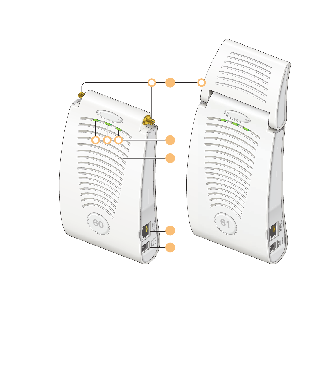
Front View
A B
CBA
1
2
3
4
5
FIGURE 1-1 Aruba 60/61 Front View
2Aruba60/61 Part 0500034-05
Installation Guide October 2004
Page 7

Antenna fixtures for Wireless Communications
1
Depending on the model, the AP will have one of the following:
A
Aruba AP60–Two Reverse Polarity SMA (RP-SMA) connectors for attaching separate
antennas (not included). For details, see “Aruba AP 60 Detachable Antennas” on page 24.
B
Aruba AP61–Built-in swivel array with dual, tri-band, omnidirectional antennas
2
Indicator LEDs
During operation, the Aruba 60/61 LEDs provide the following information:
TABLE 1-1 Aruba 60/61 LEDs
LED State Description
A
PWR Off The device is off - no power.
Green-Solid The device is powered and operating.
B
ENET Off No link on the FE port. No connection to the network.
Green-Solid Ethernet link detected on the FE port.
Green-Flashing Transmitting or receiving data across the FE port.
Flashing rate is proportional to network activity.
C
WLAN Off The wireless interface is disabled or down.
Green-Solid The wireless interface is enabled and functioning as an
Access Point.
Green-Flashing The wireless interface is enabled and functioning as an
Air Monitor.
Note LEDs on the Aruba WLAN Switch provide additional status and security informa-
tion about connected APs.See the Aruba AirOS User Guide for more information.
3
Air Vents
These vents promote proper air circulation for cooling the device. Do not allow these vents to
be obstructed by mounting equipment, network cables, or any other material.
4
FE Port
This port attaches the Aruba 60/61 to a 10Base-T/100Base-TX (twisted-pair) Ethernet LAN
segment. This port also supports Serial and Power Over Ethernet (SPOE).
See Appendix A for port and cable specifications.
Introduction 3
Chapter 1
Page 8
DC Power Socket
5
This socket is used to connect the optional AC power adapter (not included). If POE is being
used to supply power to the Aruba 60/61, the power adapter is not necessary.
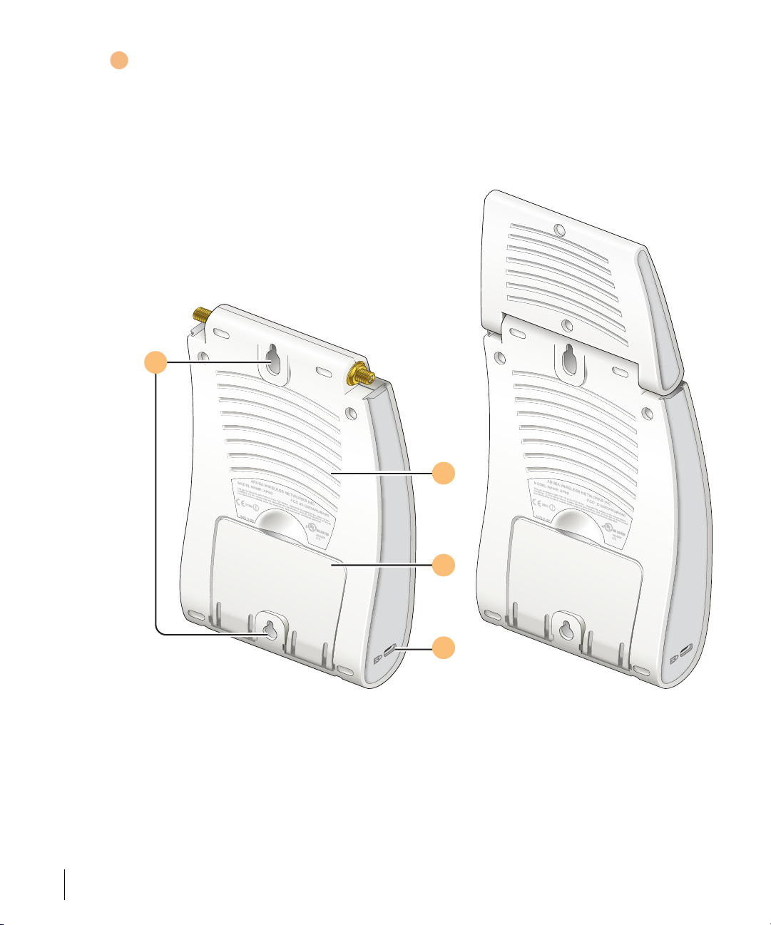
Back View
1
2
3
4
FIGURE 1-2 Aruba 60/61 Back View
4Aruba60/61 Part 0500034-05
Installation Guide October 2004
Page 9

Mounting Slots
1
The keyhole-shaped slots on the back of the chassis are used for mounting the Aruba 60/61.
2
Air Vents
These vents promote proper air circulation for cooling the device. Do not allow these vents to
be obstructed by mounting equipment, network cables, or any other material.
3
Fold-Out Stand
This fold-out stand allows the Aruba 60/61 to be stood upright on a table or shelf.
4
Kensington Security Slot
This slot is compatible with a Kensington MicroSaver Security Cable (not included) which
can be used to prevent the unauthorized removal of the Aruba 60/61 from its installed
location. To secure the Aruba 60/61, wrap a security cable around an immovable object, insert
the cable’s lock into the Kensington Security Slot, and turn the key.
Note The serial number and model number are on the bottom of the unit.
The Aruba AP Setup Process
Setting up an Aruba AP typically consists of four stages:
1 WLAN Planning—The administrator determines how many Aruba APs will be needed
for their wireless network strategy and where they will be deployed. This can be easily
accomplished using Aruba’s automated RF Plan site-survey software (available
separately).
2 AP Provisioning—Provisioning provides each Aruba AP with initial settings that allow it
to locate the host Aruba WLAN Switch. Depending on the network topology and
services, AP provisioning can be performed manually for each AP or plug-and-play for
batches of APs.
AP provisioning is discussed in Chapter 2.
3 AP Deployment—Once provisioned, the AP can be physically installed at its intended
place of operation.
AP deployment is covered in Chapter 3.
Introduction 5
Chapter 1
Page 10

4 AP Configuration—The administrator defines the operational behavior for each Aruba
AP, such as RF characteristics and security features.
For AP configuration information, refer to the Aruba AirOS User Guide.
6Aruba60/61 Part 0500034-05
Installation Guide October 2004
Page 11

CHAPTER 2
Provisioning Access
Points
Access Points are radio broadcast devices and as such are subject to governmental regulation.
Network administrators responsible for the configuration and operation of Access Points must
comply with local broadcast regulations. Specifically, Access Points must use channel
assignment and antenna gain settings (for detachable antennas) appropriate to the location in
which the Access Point will be used. Aruba Networks, in compliance with governmental
requirements, has designed the AP60 and AP61 such that only authorized network
administrators can change these settings. For more information on Access Point configuration,
refer to the AirOS User Guide.
Provisioning provides the AP with initial network settings that allow it to locate the host Aruba
WLAN Switch. The following provisioning methods (listed in the order of preference
recommended by Aruba Networks) are available:
z Plug and Play—Also known as the Aruba Discovery Protocol. This is the easiest method
for AP provisioning. With plug and play, Aruba APs can be connected to the network and
brought into operation automatically. Although plug and play requires no manual
intervention for the APs, this method does require specific services to be configured on
your network in advance.
z AP Provisioning—Using this AP programming mode, AP configuration parameters are
defined on the WLAN switch (using the CLI or Web interface) and then uploaded to the
APs.
This method can be used for adding Aruba APs to a highly customized network, or
greatly simplified for the most common provisioning.
Provisioning Access Points 7
Chapter 2
Page 12

z Manual Provisioning—APs can be individually provisioned using a serial console terminal
connected to the AP. Although this method is complex and requires considerable care,
manual provisioning can be used in almost any scenario, with or without access to the
WLAN switch.
Note Manual provisioning is intended for use when no Aruba WLAN Switch
is available, and is not generally recommended as the primary
method of AP provisioning. Plug and play or AP programming mode
are the preferred provisioning methods.
Each of these three methods is explained in the following sections. Use these procedures for
initial provisioning of APs. To change the configuration for APs that have already been
provisioned, go to Maintenance > Program AP > Re-Provision. See the AirOS User Guide for
more information on reprovisioning existing APs.
CAUTION—When an AP60 powers up for the first time, the WLAN switch
will recognize that it is detachable-antennas capable. The network
administrator must set the antenna gain manually before the AP60 can
function as an Access Point. Until the antenna gain is set, the AP60 with
detachable antennas will function as an Air Monitor but will not process
wireless packets as an Access Point. Refer to the AirOS User Guide for
instructions on manually setting antenna gain.
Aruba Discovery Protocol
Aruba Discovery Protocol (ADP) is a plug and play provisioning tool for AP60/61 Access
Points. ADP performs two tasks:
z Obtains the IP address of the TFTP server from which it downloads the AP boot image
z It discovers the IP address of the master Aruba WLAN switch in the network from which
the AP can download its configuration.
The address of the TFTP server that ADP discovers is the equivalent of the BOOTROM
environment variable serverip. The IP address of the Aruba master switch is the equivalent of
the environment variable master.
ADP can discover these values using DHCP or by discovery. In the case of DHCP, ADP relies
on a DHCP server which is configured to return the IP address of the Master switch using the
Vendor Specific Options in DHCP. To facilitate ADP, Aruba APs include this Vendor Specific
8Aruba60/61 Part 0500034-05
Installation Guide October 2004
Page 13

Option in the requested Option list, and if the DHCP server is configured to return the IP
address of the Master switch, the IP address will be a part of the DHCP response. This is used
by the AP to get its image as well as its configuration.
Discovery of the serverip and master variables is necessary when the DHCP response does not
include the Vendor Specific option. The AP attempts to discover an Aruba Master switch by
sending multicast packets and broadcast packets on its subnet. To use the ADP discovery
method, the ADP discovery mechanism needs to be enabled on the Aruba Master Switch
(using the adp discovery enable command).
If multicast routing is enabled in the IP network between the AP and the Master switch
(which can be any one or more Aruba WLAN switches in the network), the IGMP-Join option
should be enabled on the Aruba WLAN switch (using the adp igmp-join enable
command). If multicast routing is not enabled on the network, the Aruba WLAN switches
need to be on the same broadcast domain as the AP or an “IP Helper” must be configured to
direct the broadcast ADP packets to the Aruba WLAN switch.
Once these discovery prerequisites are met, the switch will respond to APs with the IP address
of the Master Aruba switch. The APs can then obtain their image and configuration.
To enable ADP on an Aruba WLAN switch, enter:
(A5000) (config) #adp discovery enable
To enable IGMP-Join on an ADP multicast group on an Aruba WLAN switch, enter:
(A5000) (config) #adp igmp-join enable
Note If you have location-specific configurations for your Access Points, you will
need to apply this configuration information using AP Reprovisioning.
Refer to the AirOS User Guide for details on AP Reprovisioning and see
the feature description below.
AP Reprovisioning
AP Reprovisioning is the process by which APs are assigned, for example, location codes.
Location codes are important for recalibration and triangulation. For details on AP
Reprovisioning, see the AirOS User Guide.
Provisioning Access Points 9
Chapter 2
Page 14

AP Provisioning
AP Provisioning is useful for brand new APs with default configurations. To perform AP
Provisioning from the GUI:
1Go to
Maintenance > Program AP.
On this window, there are two tabs:
tab is selected by default.
Provisioning and Reprovisioning. The Provisioning
FIGURE 2-1 Provisioning Tab
2 Configure the APs Subnet and Netmask.
This is the subnet from which the AP gets an IP during provisioning. (This is not the IP
address the AP will use when deployed.)
10 Aruba 60/61 Part 0500034-05
Installation Guide October 2004
Page 15

3 Select the Port or Port range for provisioning.
To set the Port Range, select the first and the last ports of your range. All the ports in
between are automatically selected. (Ports have to be sequentially assigned.)
4 Enter the required information and click
Enable.The Port Range screen displays.
FIGURE 2-2 Port Range Screen
5 Specify the AP 60/61-specific parameters.
Configure the gain value appropriate for the location in which this AP will be deployed.
(See Ta b l e 3 - 1 for appropriate antenna gain values.) Complete specifying Master
Discovery and IP Settings and click
Apply.
Provisioning Access Points 11
Chapter 2
Page 16

6 Plug the AP into one of the ports configured for provisioning.
If your AP is already plugged into the port, unplug it and plug it in again.
If AP is connected through POE, enter (in interface mode) no poe followed by poe.
The AP will come up with an IP from the provisioning subnet
After the AP comes up it should be in the provisioning list. Provisioning list shows the list
of APs which are plugged into the provisioning ports.
7Click the Refresh link (not the browser Refresh option) to see if the AP entry has
displayed.(This might take a moment.)
If you cannot see the entry after 1-2 minutes, click Refresh again.
The Clear Table button appears after an entry in the list appears.
To erase all the table entries, click Clear Table. (You cannot clear selected entries.) If a
number of APs are provisioned and you click Clear Table, only the entries which come
up afterwards can be provisioned.
If the entry does not show up in the AP list, check network connectivity. Go to the AP
console and verify if the AP has come up with the IP from the provisioning subnet.
8 After the entry shows up on the page, configure the location, Host IP/Name, Master
IP address.
If AP is going to be assigned a static IP, click Use the following IP Address and enter
the IP address, Netmask, Gateway IP.
If the AP is going to obtain an IP address using DHCP, click Use IP Address Using
DHCP.
9 After configuring the required parameters, select the entry from the list (AP to which the
configuration has to be applied) and click Apply.
The State field changes from U (Unprovisioned) to In Progress.
10 After a few seconds, click the Refresh link again and the State will have changed to P
(Provisioned).
Note Check that the configured parameters are reflected in the AP list entry.
Note Aruba Networks recommends that you provision each AP for a unique
location as suggested by site-survey planning. Label each AP with this
location information and place the AP in its proper location. Failure to
place APs in the location for which they were provisioned will reduce the
effectiveness of such RF features as triangulation.
12 Aruba 60/61 Part 0500034-05
Installation Guide October 2004
Page 17

11 Click Back to go into the previous page
We can see that the Subnet is still configured and Port/s are selected.
12 When finished provisioning APs, click Disable to disable AP Provisioning.
Note Disable AP Provisioning after all the required APs are provisioned. Ports
that are enabled for provisioning do not handle traffic. Therefore plugging
an already provisioned AP into a port still set to provisioning mode will prevent that AP from functioning.
Now the AP is configured with the Parameters given
13 Reboot the AP so the AP will come up with the new configured parameters.
Use the Reprovisioning tab for APs which are already deployed but need to be reconfigured.
See the AirOS User Guide for information on reprovisioning.
Provisioning Access Points 13
Chapter 2
Page 18

Manual Provisioning
Requirements
z A console terminal (or workstation with terminal emulation software) with an available
serial communications port using a DB-9 male connector.
z An Aruba serial breakout adapter kit, Part Number CA-SPOE-ADAPT-3, (not included).
(See “Connecting the Console Terminal” on page 15.)
z Access to the Aruba 60/61 FE port through one of the following:
z Direct contact with the AP, or
z If the AP is already deployed, you must have access to the end of the FE cable that leads
directly to the AP with no intervening hubs, routers, or other networking equipment.
The cable must be an 8-conductor, Category 5 UTP, straight-through FE cable with
RJ-45 connectors.
z A power source for the Aruba 60/61. Use one of the following:
z An optional AC power adapter (not included) and an AC power outlet rated at
100~240 V, 50~60 Hz, or
z The Aruba 60/61 FE port connected to an Aruba 800, 2400, or 5000 WLAN switch
that supports IEEE 802.3af Power Over Ethernet (POE) via a 4- or 8-conductor,
Category 5 UTP, straight-through FE cable.
1
Note Only IEEE 802.3af Power Over Ethernet is supported for manual
provisioning. “Inline” or “midspan” POE devices requires Aruba serial
breakout adapter, Part Number CA-SPOE-ADAPT-4.
1.IEEE 802.3af-complaint devices like the AP60 and AP61 use the same wire pairs for data versus
for power. Within the 802.3af standard, there are two sub-specifications on how wire pairs are assigned. Aruba conforms to 802.3af, subparagraph a. If your POE installation uses all-Aruba equipment, you are assured proper operation. However, if you use non-Aruba POE equipment, make
sure it conforms to the same standard that Aruba uses. Using POE equipment using IEEE 802.3af
subparagraph b wiring assignments, or POE equipment not conforming to the 803.2af standard
may result in damaged equipment.
14 Aruba 60/61 Part 0500034-05
Installation Guide October 2004
Page 19

Connecting the Console Terminal
Manual provisioning requires this procedure. You must use the serial console breakout adapter
cable to be able to access the serial console interface to the AP60/61 while allowing the device
to be powered by the AC adapter or POE (from an Aruba WLAN switch).
#ONSOLE#ONNECTION
VIADIRECTACCESSTO!0
#ONSOLE#ONNECTION
VIANETWORKINGCLOSET
$EPLOYED
,OCATION
3ERIAL
#ONSOLE
4ERMINAL
,!.
!RUBA!0 !RUBA!0
"REAKOUT
3ERIAL
"REAKOUT
#ONSOLE
4ERMINAL
FIGURE 2-3 Aruba 60/61 Console Topologies
Note The LAN connections are optional unless POE is used to power the AP.
Console Access to the AP
DB-9 Connector
2
to Console Terminal
"T o AP" Connector
1
to AP FE Port
"To Network" Connector
to FE Coupler
3
to LAN FE Cable
To LAN
FIGURE 2-4 Connecting Directly to the AP
1 Connect the adapter’s “To AP” RJ-45 connector to the Aruba 60/61 FE Port.
2 Connect the adapter’s DB-9 connector to the serial port on the console terminal.
3 Connect the adapter’s “To Network” RJ-45 connector to the LAN.
The LAN connection is optional unless POE is being used to power the AP. For
convenience, the adapter kit includes an FE coupler to connect RJ-45 cable ends together.
Provisioning Access Points 15
Chapter 2
Page 20

4 Connect power to the Aruba 60/61.
CAUTION—Be sure to comply with electrical grounding standards during
all phases of installation and operation of the AP. Do not allow the
Aruba 60/61 or optional power adapter (if used) to be connected to or make
contact with metal or power outlets on a different electrical ground than the
device to which it is connected. Also, never connect the AP to external
storm grounding sources.
The Aruba 60/61 can receive electrical power using the following options:
z POE–If connecting the Aruba 60/61 to a device that supplies IEEE 802.3af compliant
POE, no additional power connection is necessary.
z Power Outlet
Note When the Aruba 60/61 is installed in an air-handling space, as
described in NEC (2002) Article 300.22(C), POE must be used
instead of a power outlet.
If local regulations and practices permit, connect the optional AC power adapter (not
included) to the DC power socket on the rear panel of the Aruba 60/61 and plug it into an
appropriate power outlet.
CAUTION—To prevent personal injury or damage to equipment, use
only the AC power adapter certified for this device in the country where
it is used.
Note The indicator LEDs on the Aruba 60/61 will remain dark during this proce-
dure.
5 Set your local terminal to use the following communications:
TABLE 2-1 Console Terminal Settings
Baud Rate Data Bits Parity Stop Bits Flow Control
9600 8 None 1 None
6 Establish console communication.
Press <Enter> a few times to establish communication between the Aruba 60/61 and
terminal.
16 Aruba 60/61 Part 0500034-05
Installation Guide October 2004
Page 21

7 From the Aruba 60/61 console, access the apboot prompt.
Depending on the Aruba 60/61 status, you will see one of the following on your terminal:
z Autoboot countdown—The countdown prompt allows you to interrupt the normal
startup process and access the apboot prompt where provisioning is performed.
APBoot 1.2.1 (Apr 7 2004 - 08:54: 57)
CPU: AR2313 MIPS-32 at 180 MHz: 16 kB I-Ca che 16 kB D-Cache
Board: Merlot Local Bus at 90 MHz
DRAM: 32 MB
POST: passed
FLASH: 4 MB
Net: en0 lo0
Hit any key to stop autoboot: 0
To access the apboot prompt, press any key (such as <Enter>) before the timer expires.
If the countdown expires before you can interrupt it, turn the device off and then back on.
z TFTP time out—If the Aruba 60/61 cannot locate an Aruba WLAN Switch on its
network port, the following type of output is repeatedly displayed:
Loading FLASH image...
Verifying checksum... failed!
BOOTP broadcast 1
DHCP IP address: 10.1.2.250
DHCP subnet mask: 255.255.255.0
DHCP def gateway: 10.1.2.1
DHCP DNS server: 10.1.1.2
DHCP DNS domain: arubanetworks.c om
DHCP Aruba server: 10.1.2.11
Loading elf file: 10.1.2.11:mips.a ri
Loading: T T T T T T T T T
Retry count exceeded; starting again
Press <Control-C> to interrupt this process and access the apboot prompt.
Once the apboot prompt is displayed, perform provisioning as described in the next section.
Provisioning Access Points 17
Chapter 2
Page 22

Setting Aruba 60/61 Parameters
1From the apboot prompt, configure the host information, if necessary.
In order to provide centralized management of the APs, each Aruba AP downloads its
software image and configuration files from a master Aruba WLAN Switch.
Setting the correct host information depends on the following:
z Does your network use direct IP addresses or DNS with host names?
z If using host names, is aruba-master acceptable for the master WLAN switch, or do
you need to define a different name?
Depending on your answers, select one of the following steps:
z My network uses DNS and the aruba-master host name is acceptable.
This is the default. It requires your DNS to be configured to resolve “aruba-master” to the IP address of the master Aruba WLAN Switch. Unless your system has
been previously configured for different settings, you can skip to Step 2.
Otherwise, if your system was previously configured for a different setup, manually
set the servername environment variable to the default host name:
apboot> setenv servername aruba-master
Note The master and serverip environment variables also affect how
AP source files are selected and should be cleared when using this
approach. To clear a variable, enter the setenv variable command
with no host name or address value:
apboot> setenv master
apboot> setenv serverip
When finished, proceed to Step 2.
z My network uses DNS, but I will use a different host name for the WLAN
switch.
This requires that the servername variable be configured with your chosen host
name for the master Aruba WLAN Switch. It also requires that your DNS be configured to resolve the specified host name to the IP address of the master Aruba WLAN
Switch.
To manually set the host name, use the following command:
apboot> setenv servername
18 Aruba 60/61 Part 0500034-05
Installation Guide October 2004
<WLAN switch host name>
Page 23

Note The master and serverip environment variables also affect how
source files are selected and should be cleared when using this
approach. To clear a variable, enter the setenv variable command
with no host or address value.
When finished, proceed to Step 2.
z My network uses direct IP addresses instead of DNS.
If using direct IP addresses in your network, use the following commands:
apboot> setenv serverip
apboot> setenv master
<WLAN switch IP address>
<WLAN switch IP address>
Note If the servername variable is configured in this scenario, it will be
ignored.
2 Specify an IP address for a specific AP, if necessary.
If using DHCP, the AP will obtain its IP address automatically and you can skip this step.
Otherwise, configure the AP with a static IP address using the following commands:
apboot> setenv ipaddr
apboot> setenv netmask
apboot> setenv gatewayip
<static IP address for the AP>
<static IP address mask>
<default gateway IP address>
3 Set the location for the specific AP, if necessary.
Location settings depend on how much control you want over configuring logical groups
of APs in the future.
z Default Locations
If you wish all APs treated as a single entity for configuration and accounting purposes, you can use the default location profile (255.255.65535) and skip to Step 5.
Provisioning Access Points 19
Chapter 2
Page 24

Note If using default locations during initial provisioning, you can later
reconfigure the APs to use specific location IDs using the Aruba
WLAN Switch management tools.
z Specific Locations
By setting specific location IDs for each AP, you can later apply configuration changes
or collect statistics and information for specific groups of APs (for example, all APs on
a particular floor in a particular building).
To set a specific location for an individual AP, the following command is used:
setenv location <building number>.<floor number>.<device number>
where the following fields are required:
Building Number A unique number (1-254) is required for each building in your
campus.
Floor Number Within any building, a unique number (1-254) is required for each
floor.
Device Number Within any floor, a unique number (1-65534) is required for each
access point or air monitor.
If you performed the recommended site survey using the Aruba RF Plan tool, the
location data for all access points and air monitors can be found on the tool’s deployment page (see the Aruba RF Plan User’s Guide).
If you prefer to enter the location data manually, record the location ID you set for
each access point and air monitor along with the following:
20 Aruba 60/61 Part 0500034-05
Installation Guide October 2004
Page 25

Device Description Note the intended function of the device (access point or dedicated
air monitor) and a brief description of its service location.
X, Y Coordinates For each access point and air monitor, measure its X and Y position
(in feet) relative to the bottom-left corner of the building plan as
seen from overhead. For example:
Y
262 ft.
98
0,0 126
X
418 ft.
Use the same fixed point and orientation for all floors in a building.
4 Save the configuration and reboot the Aruba 60/61.
apboot> save
apboot> boot
Once the Aruba 60/61 boots, disconnect it and mount it in its intended service location (see
Provisioning Access Points on page 23).
Provisioning Access Points 21
Chapter 2
Page 26

22 Aruba 60/61 Part 0500034-05
Installation Guide October 2004
Page 27

CHAPTER 3
AP Deployment
This chapter covers the following topics:
z Physical mounting of the Aruba 60/61
z Connecting the required cables
Mounting the Aruba 60/61
When provisioning is complete, mount the Aruba 60/61 at its intended service location.
The Aruba 60/61 Access Points with or without external antennas are intended only for
installation in Environment A as defined in IEEE 802.3.af. All interconnected equipment
must be contained within the same building, including the interconnected equipment's
associated LAN connections. (When using an external antenna, 5.150 to 5.250 MHz are
blocked.)
Select a location as close as possible to the center of the intended coverage area. If necessary,
use the Aruba RF Plan site survey tool to determine the optimum locations for your access
points and air monitors.
The service location should be free from obstructions or obvious sources of interference.
Normally, the higher you place an access point or air monitor, the better its performance.
If external antennas are used, make sure that they and their associated wiring are located
entirely indoors. TheAruba 60/61 and any optional external antennas are not suitable for
outside use.
AP Deployment 23
Chapter 3
Page 28

The Aruba 60/61 can be mounted on a wall or suspended from above (not shown) using
one of the optional mounting kits (dimensions vary) in the following ways:
1 2
FIGURE 3-1 Aruba 60/61 Mounting Options
3
Note For dimensions, see “Product Specifications”. Allow 5 cm (2")
additional space on the right-hand side for cables. Measurements for
the Aruba AP 60 depend on attached antennas, which vary.
Aruba AP 60 Detachable Antennas
Before deploying the Aruba AP 60, attach the appropriate antennas (not included). The
antenna connections should be tightened by hand to avoid overtightening.
The Aruba AP 60 has dual Reverse Polarity SMA (RP-SMA) female antenna connectors that
accept a variety of high-gain detachable antennas. See Ta b l e 3 - 1 for the list of FCC approved
antennas tested for use with the AP 60.
Make sure that all external antennas and their associated wiring are located entirely indoors. The
Aruba AP 60 Access Points and their optional external antennas are not suitable for outside use.
24 Aruba 60/61 Part 0500034-05
Installation Guide October 2004
Page 29

FCC-Approved Detachable Antennas
The following table lists the antennas which are approved for use with the AP 60.
TABLE 3-1 FCC-Approved Detachable Antennas
Aruba Part # Description
MULTI-BAND ANTENNA
AP-ANT-1 Tri-Band, High-Gain,
Omni-Directional
Antenna (Indoor)
(Swivel Connector)
2.4Ghz (802.11B/G)
AP-ANT-2 High-Gain,
Omni-Directional
Cylindrical (Indoor)
with RP-SMA
Connector
AP-ANT-3 High-Gain,
Bi-Directional Patch
Antenna (Indoor) with
RP-SMA Connector
AP-ANT-4 High-Gain,
Directional Patch
Antenna (Indoor) with
RP-SMA Connector
Gain
dbi
Manufacturer Man. Part #
5 Nearson T614AH-2.45/
5.X-S
6 Centurion IG2450-RPSM
A
5 Centurion IB2450-RPSM
A
9 Centurion ID240-RPSM
A/CAF94379
AP-ANT-5 Down-Tilt,
Omni-Directional
Patch Antenna
(Indoor) with
RP-SMA Connector
AP-ANT-7 High-Gain Directional
Patch Antenna (Indoor
/ Outdoor) with
RP-SMA Connector
3.5 Cushcraft SQ2403PG36R
SM
11.5 HD Comms. Corp PCW24-08012AFL/HD1965
6
AP Deployment 25
Chapter 3
Page 30

TABLE 3-1 FCC-Approved Detachable Antennas (Continued)
AP-ANT-8 High-Gain,
Omni-Directional
Cylindrical (Indoor /
Outdoor) with
RP-SMA Connector
5Ghz (802.11A)
AP-ANT-10 High-Gain,
Omni-Directional
Cylindrical (Indoor /
Outdoor) with
RP-SMA Connector
AP-ANT-11 Down-Tilt,
Omni-Directional
Patch Antenna
(Indoor) with
RP-SMA Connector
AP-ANT-12 High-Gain,
Directional Patch
Antenna (Indoor /
Outdoor) with
RP-SMA Connector
5 Cushcraft S2403BPX36R
SM
5.5 Cushcraft S5153WBPX3
6RSM
3.5 Cushcraft SQ5153WP36
RSM
14 Cushcraft S52514WP36R
SM
Free-Standing Placement
To place the Aruba 60/61 indoors on a flat table or shelf:
26 Aruba 60/61 Part 0500034-05
Installation Guide October 2004
Page 31

1 Flip open the stand located on the back of the Aruba 60/61:
FIGURE 3-2 Aruba 60/61Fold-Out Stand
2 Place the device on a sturdy table or shelf.
CAUTION—Do not place the Aruba 60/61 in any place where it could fall
on people or equipment. For more secure installation, use one of the
optional mounting kits.
3 Orient the antennas.
For best performance, swivel the individual antennas (Aruba AP 60) or antenna array (Aruba
AP61) so that they are oriented vertically. Once mounting is complete, connect the required
cables (see instructions on page 30).
AP Deployment 27
Chapter 3
Page 32

Using the Built-In Mounting Slots
The keyhole-shaped slots on the back of the Aruba 60/61 can be used to attach the device
upright to an indoor wall or shelf.
CAUTION—Do not use the mounting slots to hang the Aruba 60/61 from
the ceiling, sideways, or in any place where it could fall on people or equipment. For more secure installation, use one of the optional mounting kits.
To hang the Aruba 60/61 upright using the mounting slots, perform the following steps.
1 Install two screws in the wall or shelf as shown in Figure 3-3:
Screw/Nail Positions
(fastened to wall or shelf)
12.7 cm
(5.00")
Screw/Nail Dimensions
Maximum Minimum
7.0 mm
3.0 mm
0.27"
0.12"
2.0 mm
3.8 mm
clearance
from surface
0.08"
0.15"
clearance
from surface
5.8 mm
0.23"
1.3 mm
clearnace
from surface
0.05"
clearance
from surface
FIGURE 3-3 Mounting Screw Specifications
If attaching the device to drywall, we recommend using appropriate wall anchors (not
included) as shown in Figure 3-4 on page 29.
28 Aruba 60/61 Part 0500034-05
Installation Guide October 2004
 Loading...