

Page 1

Aruba 2920 Management and
Configuration Guide for ArubaOSSwitch 16.05
Part Number: 5200-4205a
Published: April 2018
Edition: 2
Page 2

©
Copyright 2017 Hewlett Packard Enterprise
Notices
The information contained herein is subject to change without notice. The only warranties for Hewlett Packard
Enterprise products and services are set forth in the express warranty statements accompanying such products
and services. Nothing herein should be construed as constituting an additional warranty. Hewlett Packard
Enterprise shall not be liable for technical or editorial errors or omissions contained herein.
Confidential computer software. Valid license from Hewlett Packard Enterprise required for possession, use, or
copying. Consistent with FAR 12.211 and 12.212, Commercial Computer Software, Computer Software
Documentation, and Technical Data for Commercial Items are licensed to the U.S. Government under vendor's
standard commercial license.
Links to third-party websites take you outside the Hewlett Packard Enterprise website. Hewlett Packard Enterprise
has no control over and is not responsible for information outside the Hewlett Packard Enterprise website.
Acknowledgments
Intel®, Itanium®, Pentium®, Intel Inside®, and the Intel Inside logo are trademarks of Intel Corporation in the United
States and other countries.
Microsoft® and Windows® are either registered trademarks or trademarks of Microsoft Corporation in the United
States and/or other countries.
Adobe® and Acrobat® are trademarks of Adobe Systems Incorporated.
Java® and Oracle® are registered trademarks of Oracle and/or its affiliates.
UNIX® is a registered trademark of The Open Group.
Page 3

Contents
Chapter 1 About this guide........................................................................... 24
Applicable products..................................................................................................................................24
Switch prompts used in this guide........................................................................................................... 24
Chapter 2 Time Protocols..............................................................................25
General steps for running a time protocol on the switch..........................................................................25
TimeP time synchronization.......................................................................................................... 25
SNTP time synchronization...........................................................................................................25
NTP time synchronization............................................................................................................. 26
timesync Command................................................................................................................... 26
Selecting a time synchronization protocol................................................................................................26
Disabling time synchronization................................................................................................................ 27
SNTP: Selecting and configuring............................................................................................................. 27
Viewing and configuring SNTP (Menu)......................................................................................... 28
Viewing and configuring SNTP (CLI).............................................................................................30
Configuring (enabling or disabling) the SNTP mode.......................................................... 31
SNTP client authentication............................................................................................................37
Requirements..................................................................................................................... 37
Configuring the key-identifier, authentication mode, and key-value (CLI)..........................37
Configuring a trusted key................................................................................................... 38
Associating a key with an SNTP server (CLI).................................................................... 39
Enabling SNTP client authentication.................................................................................. 39
Configuring unicast and broadcast mode for authentication.............................................. 40
Viewing SNTP authentication configuration information (CLI)............................................40
Saving configuration files and the include-credentials command.......................................41
TimeP: Selecting and configuring............................................................................................................ 43
Viewing, enabling, and modifying the TimeP protocol (Menu)...................................................... 44
Viewing the current TimeP configuration (CLI)..............................................................................45
Configuring (enabling or disabling) the TimeP mode......................................................... 46
SNTP unicast time polling with multiple SNTP servers............................................................................49
Displaying all SNTP server addresses configured on the switch (CLI)......................................... 50
Adding and deleting SNTP server addresses............................................................................... 50
Adding addresses...............................................................................................................50
Deleting addresses.............................................................................................................50
Operating with multiple SNTP server addresses configured (Menu)....................................................... 51
SNTP messages in the Event Log........................................................................................................... 51
Network Time Protocol (NTP).................................................................................................................. 51
Commands....................................................................................................................................51
timesync ntp....................................................................................................................... 51
ntp...................................................................................................................................... 52
[no] ntp............................................................................................................................... 52
ntp enable...........................................................................................................................53
ntp authentication............................................................................................................... 53
ntp authentication key-id ................................................................................................... 54
ntp max-association........................................................................................................... 54
ntp server........................................................................................................................... 55
ntp server key-id.................................................................................................................57
ntp ipv6-multicast............................................................................................................... 57
debug ntp........................................................................................................................... 58
Contents 3
Page 4

ntp trap............................................................................................................................... 58
show ntp statistics.............................................................................................................. 59
show ntp status.................................................................................................................. 60
show ntp associations........................................................................................................ 60
show ntp authentication......................................................................................................61
Validation rules................................................................................................................... 62
Event log messages........................................................................................................... 64
Monitoring resources............................................................................................................................... 65
Displaying current resource usage................................................................................................65
Viewing information on resource usage........................................................................................ 66
Policy enforcement engine................................................................................................. 66
Usage notes for show resources output.............................................................................67
When insufficient resources are available.....................................................................................68
Chapter 3 Port Status and Configuration.....................................................69
Viewing port status and configuring port parameters...............................................................................69
Connecting transceivers to fixed-configuration devices................................................................ 69
Viewing port configuration (Menu).................................................................................................71
Configuring ports (Menu)....................................................................................................72
Viewing port status and configuration (CLI).................................................................................. 73
Dynamically updating the show interfaces command (CLI/Menu)..................................... 74
Customizing the show interfaces command (CLI).........................................................................74
Error messages associated with the show interfaces command........................................76
Viewing port utilization statistics (CLI)...........................................................................................76
Operating notes for viewing port utilization statistics..........................................................77
Viewing transceiver status (CLI)....................................................................................................77
Operating Notes................................................................................................................. 77
Enabling or disabling ports and configuring port mode (CLI)........................................................ 78
Enabling or disabling flow control (CLI).........................................................................................79
Port shutdown with broadcast storm............................................................................................. 81
Viewing broadcast storm.................................................................................................... 81
SNMP MIB..........................................................................................................................82
Configuring auto-MDIX..................................................................................................................85
Manual override..................................................................................................................85
Configuring auto-MDIX (CLI)..............................................................................................86
Using friendly (optional) port names........................................................................................................ 87
Configuring and operating rules for friendly port names............................................................... 87
Configuring friendly port names (CLI)........................................................................................... 87
Configuring a single port name (CLI)................................................................................. 88
Configuring the same name for multiple ports (CLI)...........................................................88
Displaying friendly port names with other port data (CLI)............................................................. 88
Listing all ports or selected ports with their friendly port names (CLI)................................89
Including friendly port names in per-port statistics listings (CLI)........................................ 90
Searching the configuration for ports with friendly port names (CLI)................................. 90
Uni-directional link detection (UDLD).......................................................................................................91
Configuring UDLD......................................................................................................................... 92
Configuring uni-directional link detection (UDLD) (CLI)..................................................... 92
Enabling UDLD (CLI)..........................................................................................................93
Changing the keepalive interval (CLI)................................................................................ 93
Changing the keepalive retries (CLI)..................................................................................93
Configuring UDLD for tagged ports.................................................................................... 93
Viewing UDLD information (CLI)................................................................................................... 94
Viewing summary information on all UDLD-enabled ports (CLI)........................................94
Viewing detailed UDLD information for specific ports (CLI)................................................95
Clearing UDLD statistics (CLI)........................................................................................... 95
4 Aruba 2920 Management and Configuration Guide for
ArubaOS-Switch 16.05
Page 5

Uplink failure detection.............................................................................................................................96
Configuration guidelines for UFD.................................................................................................. 98
UFD enable/disable.......................................................................................................................98
UFD track data configuration........................................................................................................ 98
UFD minimum uplink threshold configuration............................................................................... 99
show uplink-failure-detection.........................................................................................................99
UFD operating notes................................................................................................................... 100
Error log...................................................................................................................................... 100
Invalid port error messages.........................................................................................................100
Chapter 4 Power Over Ethernet (PoE/PoE+) Operation............................101
Introduction to PoE................................................................................................................................ 101
PoE terminology..........................................................................................................................101
Planning and implementing a PoE configuration................................................................................... 101
Power requirements.................................................................................................................... 101
Assigning PoE ports to VLANs....................................................................................................102
Applying security features to PoE configurations........................................................................102
Assigning priority policies to PoE traffic...................................................................................... 102
PoE operation........................................................................................................................................ 102
Configuration options.................................................................................................................. 103
PD support.................................................................................................................................. 103
Power priority operation.............................................................................................................. 104
When is power allocation prioritized?...............................................................................104
How is power allocation prioritized?................................................................................. 104
Configuring PoE operation.....................................................................................................................104
Disabling or re-enabling PoE port operation............................................................................... 104
Enabling support for pre-standard devices................................................................................. 105
Configuring the PoE port priority................................................................................................. 105
Controlling PoE allocation........................................................................................................... 105
Manually configuring PoE power levels...................................................................................... 106
Configuring PoE redundancy...................................................................................................... 107
Changing the threshold for generating a power notice............................................................... 108
PoE/PoE+ allocation using LLDP information........................................................................................109
LLDP with PoE............................................................................................................................ 109
Enabling or disabling ports for allocating power using LLDP........................................... 110
Enabling PoE detection via LLDP TLV advertisement......................................................110
LLDP with PoE+.......................................................................................................................... 110
Overview...........................................................................................................................110
PoE allocation...................................................................................................................110
Viewing PoE when using LLDP information......................................................................111
Operating note..................................................................................................................113
Viewing the global PoE power status of the switch................................................................................113
Viewing PoE status on all ports...................................................................................................114
Viewing the PoE status on specific ports.....................................................................................116
Using the HPE 2920 Switch with an external power supply...................................................................118
Overview......................................................................................................................................118
Supported PSUs..........................................................................................................................118
Using the XPS for additional PoE power.....................................................................................119
Determining the maximum available PoE power..............................................................119
Operating rules.................................................................................................................121
Using redundant (N+1) power.......................................................................................... 122
Providing non-PoE redundant power.......................................................................................... 122
Configuring the HPE 2920 PoE switches to use the XPS...........................................................123
Enabling and disabling power from the XPS.................................................................... 123
Configuring auto-recovery................................................................................................ 123
Contents 5
Page 6

Restoring the default external power supply settings.......................................................124
Distributing power to specified ports................................................................................ 125
Example: of the power-share option.................................................................................125
Example: of adding a switch.............................................................................................125
Example: of using the force option................................................................................... 125
Reducing allocated external power.................................................................................. 126
Example: configurations..............................................................................................................126
Non-PoE configuration..................................................................................................... 127
PoE configuration for full PoE power to one XPS port..................................................... 128
PoE configuration for multiple switches............................................................................129
Viewing power information.......................................................................................................... 131
Examples for show external-power-supply.......................................................................132
Examples for show power-over-ethernet commands....................................................... 135
Example: for show running-config command................................................................... 136
PoE Event Log messages......................................................................................................................137
Chapter 5 Port Trunking.............................................................................. 138
Overview of port trunking....................................................................................................................... 138
Port connections and configuration.............................................................................................138
Port trunk features and operation.......................................................................................................... 139
Fault tolerance ........................................................................................................................... 139
Trunk configuration methods..................................................................................................................139
Dynamic LACP trunk...................................................................................................................139
Using keys to control dynamic LACP trunk configuration.................................................140
Static trunk.................................................................................................................................. 140
Viewing and configuring a static trunk group (Menu).............................................................................144
Viewing and configuring port trunk groups (CLI)....................................................................................146
Viewing static trunk type and group for all ports or for selected ports.........................................146
Viewing static LACP and dynamic LACP trunk data................................................................... 147
Dynamic LACP Standby Links.................................................................................................... 147
Configuring a static trunk or static LACP trunk group................................................................. 148
Removing ports from a static trunk group................................................................................... 148
Enabling a dynamic LACP trunk group....................................................................................... 149
Removing ports from a dynamic LACP trunk group....................................................................149
Viewing existing port trunk groups (WebAgent).....................................................................................150
Trunk group operation using LACP........................................................................................................150
Default port operation..................................................................................................................152
LACP notes and restrictions........................................................................................................153
802.1X (Port-based access control) configured on a port................................................ 154
Port security configured on a port.................................................................................... 154
Changing trunking methods............................................................................................. 154
Static LACP trunks........................................................................................................... 154
Dynamic LACP trunks...................................................................................................... 154
VLANs and dynamic LACP.............................................................................................. 154
Blocked ports with older devices...................................................................................... 155
Spanning Tree and IGMP.................................................................................................155
Half-duplex, different port speeds, or both not allowed in LACP trunks........................... 156
Dynamic/static LACP interoperation.................................................................................156
Trunk group operation using the "trunk" option......................................................................................156
How the switch lists trunk data...............................................................................................................156
Outbound traffic distribution across trunked links.................................................................................. 157
Trunk load balancing using port layers.................................................................................................. 158
Enabling trunk load balancing..................................................................................................... 159
6 Aruba 2920 Management and Configuration Guide for
ArubaOS-Switch 16.05
Page 7

Chapter 6 Port Traffic Controls................................................................... 161
Rate-limiting........................................................................................................................................... 161
All traffic rate-limiting...................................................................................................................161
Configuring in/out rate-limiting..........................................................................................161
Displaying the current rate-limit configuration.................................................................. 162
Operating notes for rate-limiting....................................................................................... 164
ICMP rate-limiting.................................................................................................................................. 165
Guidelines for configuring ICMP rate-limiting..............................................................................166
Configuring ICMP rate-limiting.................................................................................................... 166
Using both ICMP rate-limiting and all-traffic rate-limiting on the same interface.........................167
Viewing the current ICMP rate-limit configuration....................................................................... 168
Operating notes for ICMP rate-limiting........................................................................................168
Notes on testing ICMP rate-limiting..................................................................................169
ICMP rate-limiting trap and Event Log messages.......................................................................170
Determining the switch port number used in ICMP port reset commands....................... 170
Configuring inbound rate-limiting for broadcast and multicast traffic.......................................... 171
Operating Notes............................................................................................................... 172
Configuring egress per-queue rate-limiting (2920 and 5400R switches only)....................................... 173
Overview..................................................................................................................................... 173
Restrictions.......................................................................................................................173
Configuration commands............................................................................................................ 173
Rate-limit queues out command.......................................................................................174
Show commands..............................................................................................................174
show rate-limit queues..................................................................................................... 175
Rate-limiting Unknown Unicast Traffic........................................................................................ 176
rate-limit unknown-unicast in percent..........................................................176
rate-limit unknown-unicast in kbps................................................................ 177
show rate-limit unknown-unicast.......................................................................178
Rate-limiting Unknown Unicast Traffic................................................................................................... 179
rate-limit unknown-unicast in percent.................................................................... 179
rate-limit unknown-unicast in kbps...........................................................................180
show rate-limit unknown-unicast................................................................................. 181
Guaranteed minimum bandwidth (GMB)............................................................................................... 182
GMB operation............................................................................................................................ 182
Impacts of QoS queue configuration on GMB operation..................................................183
Configuring GMB for outbound traffic...............................................................................184
Viewing the current GMB configuration............................................................................186
GMB operating notes.................................................................................................................. 187
Impact of QoS queue configuration on GMB commands................................................. 187
Jumbo frames........................................................................................................................................ 187
Operating rules............................................................................................................................187
Jumbo traffic-handling...................................................................................................... 188
Configuring jumbo frame operation.............................................................................................189
Overview.......................................................................................................................... 189
Viewing the current jumbo configuration.......................................................................... 189
Enabling or disabling jumbo traffic on a VLAN................................................................. 191
Configuring a maximum frame size.............................................................................................191
Configuring IP MTU..........................................................................................................192
SNMP implementation......................................................................................................192
Displaying the maximum frame size.................................................................................192
Operating notes for maximum frame size........................................................................ 192
Troubleshooting...........................................................................................................................193
A VLAN is configured to allow jumbo frames, but one or more ports drops all inbound
jumbo frames....................................................................................................................193
Contents 7
Page 8

A non-jumbo port is generating "Excessive undersize/giant frames" messages in the
Event Log......................................................................................................................... 193
Chapter 7 Fault-Finder port-level link-flap................................................. 194
Overview................................................................................................................................................ 194
Fault-finder link-flap .............................................................................................................................. 194
Show fault-finder link-flap.......................................................................................................................196
Event Log...............................................................................................................................................197
Restrictions............................................................................................................................................ 197
Chapter 8 Configuring for Network Management Applications...............198
Using SNMP tools to manage the switch...............................................................................................198
SNMP management features......................................................................................................198
SNMPv1 and v2c access to the switch....................................................................................... 199
SNMPv3 access to the switch.....................................................................................................199
Enabling and disabling switch for access from SNMPv3 agents......................................200
Enabling or disabling restrictions to access from only SNMPv3 agents...........................200
Enabling or disabling restrictions from all non-SNMPv3 agents to read-only access...... 200
Viewing the operating status of SNMPv3......................................................................... 200
Viewing status of message reception of non-SNMPv3 messages................................... 200
Viewing status of write messages of non-SNMPv3 messages.........................................200
Enabling SNMPv3............................................................................................................ 200
SNMPv3 users................................................................................................................. 201
Group access levels......................................................................................................... 204
SNMPv3 communities...................................................................................................... 205
Viewing and configuring non-version-3 SNMP communities (Menu)............................... 206
Listing community names and values (CLI)..................................................................... 207
SNMP notifications......................................................................................................................208
Supported Notifications.................................................................................................... 209
General steps for configuring SNMP notifications............................................................209
SNMPv1 and SNMPv2c Traps......................................................................................... 209
SNMP trap receivers........................................................................................................ 210
SNMP trap when MAC address table changes................................................................ 211
SNMPv2c informs.............................................................................................................212
Configuring SNMPv3 notifications (CLI)...........................................................................213
Network security notifications...........................................................................................216
Enabling Link-Change Traps (CLI)...................................................................................218
Source IP address for SNMP notifications....................................................................... 219
Viewing SNMP notification configuration (CLI).................................................................221
Configuring the MAC address count option................................................................................ 221
Displaying information about the mac-count-notify option................................................222
Advanced management: RMON................................................................................................. 223
CLI-configured sFlow with multiple instances............................................................................. 224
Configuring sFlow (CLI)....................................................................................................224
Viewing sFlow Configuration and Status (CLI).................................................................225
Configuring UDLD Verify before forwarding...........................................................................................227
UDLD time delay......................................................................................................................... 227
Restrictions.......................................................................................................................228
UDLD configuration commands.................................................................................................. 228
Show commands.........................................................................................................................229
RMON generated when user changes UDLD mode................................................................... 229
LLDP...................................................................................................................................................... 229
General LLDP operation............................................................................................................. 230
LLDP-MED....................................................................................................................... 230
8 Aruba 2920 Management and Configuration Guide for
ArubaOS-Switch 16.05
Page 9

Packet boundaries in a network topology................................................................................... 230
LLDP operation configuration options......................................................................................... 230
Enable or disable LLDP on the switch..............................................................................231
Enable or disable LLDP-MED.......................................................................................... 231
Change the frequency of LLDP packet transmission to neighbor devices....................... 231
Change the Time-To-Live for LLDP packets sent to neighbors........................................ 231
Transmit and receive mode..............................................................................................231
SNMP notification.............................................................................................................231
Per-port (outbound) data options..................................................................................... 231
Remote management address......................................................................................... 233
Debug logging.................................................................................................................. 233
Options for reading LLDP information collected by the switch....................................................233
LLDP and LLDP-MED standards compatibility........................................................................... 233
LLDP operating rules.................................................................................................................. 234
Port trunking..................................................................................................................... 234
IP address advertisements...............................................................................................234
Spanning-tree blocking.....................................................................................................234
802.1X blocking................................................................................................................234
Configuring LLDP operation........................................................................................................234
Displaying the global LLDP, port admin, and SNMP notification status (CLI).................. 234
Configuring Global LLDP Packet Controls....................................................................... 236
Configuring SNMP notification support............................................................................ 239
Configuring per-port transmit and receive modes (CLI)................................................... 240
Basic LLDP per-port advertisement content.....................................................................240
Support for port speed and duplex advertisements..........................................................242
Port VLAN ID TLV support on LLDP........................................................................................... 243
Configuring the VLAN ID TLV...........................................................................................243
Viewing the TLVs advertised............................................................................................ 243
SNMP support.................................................................................................................. 244
LLDP-MED (media-endpoint-discovery)..................................................................................... 245
LLDP-MED endpoint support........................................................................................... 246
LLDP-MED endpoint device classes................................................................................ 246
LLDP-MED operational support....................................................................................... 246
LLDP-MED fast start control.............................................................................................247
Advertising device capability, network policy, PoE status and location data.................... 247
Location data for LLDP-MED devices.............................................................................. 250
Viewing switch information available for outbound advertisements............................................ 254
Displaying the current port speed and duplex configuration on a switch port.................. 255
Viewing advertisements currently in the neighbors MIB...................................................256
Displaying LLDP statistics................................................................................................ 257
LLDP over OOBM....................................................................................................................... 259
LLDP over OOBM commands..........................................................................................259
LLDP Operating Notes................................................................................................................ 264
Neighbor maximum.......................................................................................................... 264
LLDP packet forwarding................................................................................................... 264
One IP address advertisement per port........................................................................... 264
802.1Q VLAN Information................................................................................................ 264
Effect of 802.1X Operation............................................................................................... 265
Neighbor data can remain in the neighbor database after the neighbor is
disconnected.................................................................................................................... 265
Mandatory TLVs............................................................................................................... 265
LLDP and CDP data management..............................................................................................265
LLDP and CDP neighbor data..........................................................................................265
CDP operation and commands........................................................................................ 266
Viewing the current CDP configuration of the switch........................................................266
Viewing the current CDP neighbors table of the switch....................................................267
Enabling and Disabling CDP Operation........................................................................... 268
Contents 9
Page 10

Enabling or disabling CDP operation on individual ports................................................. 268
Configuring CDPv2 for voice transmission..................................................................................268
Filtering CDP information............................................................................................................ 270
Configuring the switch to filter untagged traffic.................................................................271
Displaying the configuration............................................................................................. 271
Filtering PVID mismatch log messages...................................................................................... 272
DHCPv4 server...................................................................................................................................... 272
Introduction to DHCPv4.............................................................................................................. 272
IP pools....................................................................................................................................... 272
DHCP options............................................................................................................................. 272
BootP support............................................................................................................................. 273
Authoritative server and support for DHCP inform packets........................................................ 273
Authoritative pools.......................................................................................................................273
Authoritative dummy pools..........................................................................................................273
Change in server behavior.......................................................................................................... 274
DHCPv4 configuration commands.............................................................................................. 274
Enable/disable the DHCPv4 server..................................................................................274
Configuring the DHCP address pool name...................................................................... 274
Authoritative..................................................................................................................... 276
Specify a boot file for the DHCP client ............................................................................ 276
Configure a default router for a DHCP client....................................................................276
Configure the DNS IP servers ......................................................................................... 276
Configure a domain name................................................................................................ 277
Configure lease time........................................................................................................ 277
Configure the NetBIOS WINS servers............................................................................. 277
Configure the NetBIOS node type....................................................................................277
Configure subnet and mask ............................................................................................ 278
Configure DHCP server options....................................................................................... 278
Configure the range of IP address................................................................................... 278
Configure the static binding information........................................................................... 279
Configure the TFTP server domain name........................................................................ 279
Configure the TFTP server address................................................................................. 279
Change the number of ping packets................................................................................ 280
Change the amount of time.............................................................................................. 280
Configure DHCP Server to save automatic bindings....................................................... 280
Configure a DHCP server to send SNMP notifications.................................................... 281
Enable conflict logging on a DHCP server....................................................................... 281
Enable the DHCP server on a VLAN................................................................................281
Clear commands.............................................................................................................. 281
Reset all DHCP server and BOOTP counters..................................................................282
Delete an automatic address binding............................................................................... 282
Show commands.........................................................................................................................282
Display the DHCPv4 server address bindings................................................................. 282
Display address conflicts..................................................................................................282
Display DHCPv4 server database agent..........................................................................282
Display DHCPv4 server statistics.....................................................................................283
Display the DHCPv4 server IP pool information...............................................................283
Display DHCPv4 server global configuration information.................................................283
Event log..................................................................................................................................... 283
Event Log Messages........................................................................................................284
LLDP Management TLV Transmission disablement..............................................................................286
Overview..................................................................................................................................... 286
Commands..................................................................................................................................286
[no] lldp config basicTlvEnable management_addr..........................................................286
lldp config......................................................................................................................... 287
Show commands.........................................................................................................................287
10 Aruba 2920 Management and Configuration Guide for
ArubaOS-Switch 16.05
Page 11

Chapter 9 Captive Portal for ClearPass..................................................... 289
Requirements.........................................................................................................................................289
Best Practices........................................................................................................................................ 290
Limitations..............................................................................................................................................290
Features.................................................................................................................................................290
High Availability...........................................................................................................................290
Load balancing and redundancy................................................................................................. 290
Captive Portal when disabled................................................................................................................ 291
Disabling Captive Portal..............................................................................................................291
Configuring Captive Portal on CPPM.....................................................................................................291
Import the HP RADIUS dictionary............................................................................................... 291
Create enforcement profiles........................................................................................................292
Create a ClearPass guest self-registration................................................................................. 293
Configure the login delay ........................................................................................................... 294
Configuring the switch............................................................................................................................294
Configure the URL key................................................................................................................295
Configuring a certificate for Captive Portal usage..................................................................................295
Display Captive Portal configuration...................................................................................................... 295
Show certificate information...................................................................................................................296
Troubleshooting..................................................................................................................................... 296
Event Timestamp not working.....................................................................................................296
Cannot enable Captive Portal..................................................................................................... 296
Unable to enable feature.............................................................................................................297
Authenticated user redirected to login page ...............................................................................297
Unable to configure a URL hash key.......................................................................................... 298
authentication command............................................................................................................. 298
show command........................................................................................................................... 298
Debug command.........................................................................................................................299
Chapter 10 Zero Touch Provisioning with AirWave and Central............. 300
Zero Touch Provisioning........................................................................................................................ 300
ZTP with AirWave.................................................................................................................................. 300
DHCP-based ZTP with AirWave................................................................................................. 300
Configuring DHCP-based ZTP with AirWave................................................................... 300
Limitations................................................................................................................................... 302
Best Practices............................................................................................................................. 302
Configure AirWave details in DHCP (preferred method).............................................................302
Configure AirWave details in DHCP (alternative method)...........................................................307
Configure AirWave details manually........................................................................................... 314
amp-server....................................................................................................................... 315
debug ztp..........................................................................................................................316
Stacking support......................................................................................................................... 316
Disabling ZTP..............................................................................................................................316
Image Upgrade........................................................................................................................... 317
Troubleshooting...........................................................................................................................317
AMP server messages..................................................................................................... 317
Activate based ZTP with AirWave...............................................................................................317
Configuring Activate-based ZTP with AirWave.................................................................317
IPsec for AirWave Connectivity..............................................................................................................318
Overview..................................................................................................................................... 318
IPsec for Management Traffic.......................................................................................... 318
IPsec Tunnel Establishment.............................................................................................319
IPsec Tunnel Failures.......................................................................................................319
Contents 11
Page 12

AirWave IP after discovery............................................................................................... 319
Configuring the Aruba controller.......................................................................................319
AirWave Controller IP configuration commands..........................................................................320
aruba-vpn type................................................................................................................. 320
Show commands.........................................................................................................................321
show aruba-vpn................................................................................................................321
show ip route.................................................................................................................... 322
show interfaces tunnel aruba-vpn.................................................................................... 322
show crypto-ipsec sa........................................................................................................323
show running-configuration.............................................................................................. 324
ZTP with Aruba Central..........................................................................................................................324
LED Blink feature........................................................................................................................ 326
Aruba Central Configuration manually........................................................................................ 326
aruba-central.................................................................................................................... 326
aruba-central support-mode................................................................................. 327
Activating ArubaOS-Switch Firmware Integration............................................................ 327
activate software-update enable...................................................................................... 328
activate software-update check........................................................................................328
activate software-update update...................................................................................... 328
show activate software-update.........................................................................................329
Troubleshooting...........................................................................................................................329
show aruba-central...........................................................................................................329
debug ztp..........................................................................................................................330
Stacking support......................................................................................................................... 330
Chapter 11 Auto configuration upon Aruba AP detection........................331
Auto device detection and configuration................................................................................................ 331
Requirements..............................................................................................................................331
Limitations................................................................................................................................... 331
Feature Interactions.................................................................................................................... 331
Profile Manager and 802.1X.............................................................................................332
Profile Manager and LMA/WMA/MAC-AUTH...................................................................332
Profile manager and Private VLANs.................................................................................332
Procedure for creating a device identity and associating a device type......................................332
device-profile name.....................................................................................................................333
device-profile type....................................................................................................................... 334
Rogue AP Isolation................................................................................................................................ 335
Limitations................................................................................................................................... 335
Feature Interactions.................................................................................................................... 336
MAC lockout and lockdown ............................................................................................. 336
LMA/WMA/802.1X/Port-Security...................................................................................... 336
L3 MAC............................................................................................................................ 337
Using the Rogue AP Isolation feature......................................................................................... 337
rogue-ap-isolation....................................................................................................................... 338
rogue-ap-isolation action.............................................................................................................338
rogue-ap-isolation whitelist..........................................................................................................339
clear rogue-ap-isolation...............................................................................................................339
Troubleshooting..................................................................................................................................... 340
Dynamic configuration not displayed when using “show running-config”....................................340
Switch does not detect the rogue AP TLVs.................................................................................340
The show run command displays non-numerical value for untagged-vlan...............................340
Show commands.........................................................................................................................341
Validation Rules...........................................................................................................................341
12 Aruba 2920 Management and Configuration Guide for
ArubaOS-Switch 16.05
Page 13

Chapter 12 Device Profile for custom device types..................................344
Procedure for creating a device identity and associating a device type................................................ 344
Chapter 13 Dynamically detecting LLDP device profiles......................... 345
device-profile.................................................................................................................................345
device-profile type-device...................................................................................................................... 345
device-profile device-type enable........................................................................................346
Associating a profile with a device......................................................................................................... 347
device-profile device-type associate.......................................................................347
show device-profile status.......................................................................................................347
show device-profile config......................................................................................................................348
show device-identity....................................................................................................................349
Chapter 14 LACP-MAD.................................................................................351
LACP-MAD commands..........................................................................................................................351
Configuration command.............................................................................................................. 351
show commands......................................................................................................................... 351
clear command............................................................................................................................351
LACP-MAD overview............................................................................................................................. 351
Chapter 15 Scalability IP Address VLAN and Routing Maximum Values
....................................................................................................................... 353
Chapter 16 Static IP Visibility......................................................................355
IP client-tracker...................................................................................................................................... 355
Chapter 17 File Transfers............................................................................ 358
Overview................................................................................................................................................ 358
Downloading switch software.................................................................................................................358
General software download rules................................................................................................358
Using TFTP to download software from a server........................................................................358
Downloading from a server to primary flash using TFTP (Menu).....................................359
Troubleshooting TFTP download failures.........................................................................361
Downloading from a server to flash using TFTP (CLI)..................................................... 362
Enabling TFTP (CLI)........................................................................................................ 363
Configuring the switch to download software automatically from a TFTP server using
auto-TFTP (CLI)............................................................................................................... 363
Using SCP and SFTP................................................................................................................. 364
Enabling SCP and SFTP.............................................................................................................365
Disabling TFTP and auto-TFTP for enhanced security.................................................... 365
Enabling SSH V2 (required for SFTP)..............................................................................367
Authentication...................................................................................................................367
SCP/SFTP operating notes.............................................................................................. 368
Troubleshooting SSH, SFTP, and SCP operations.......................................................... 369
Using Xmodem to download switch software from a PC or UNIX workstation........................... 370
Downloading to primary flash using Xmodem (Menu)......................................................370
Downloading to primary or secondary flash using Xmodem and a terminal emulator
(CLI)................................................................................................................................. 371
Contents 13
Page 14

Using USB to transfer files to and from the switch......................................................................372
Downloading switch software using USB (CLI)................................................................ 372
Switch-to-switch download..........................................................................................................374
Switch-to-switch download to primary flash (Menu)......................................................... 374
Downloading the OS from another switch (CLI)............................................................... 374
Using AirWave to update switch software...................................................................................375
Using IMC to update switch software..........................................................................................375
Copying software images.......................................................................................................................376
TFTP: Copying a software image to a remote host (CLI)............................................................376
Xmodem: Copying a software image from the switch to a serially connected PC or UNIX
workstation (CLI)......................................................................................................................... 376
USB: Copying a software image to a USB device (CLI)............................................................. 376
Transferring switch configurations......................................................................................................... 377
TFTP: Copying a configuration file to a remote host (CLI)..........................................................377
TFTP: Copying a configuration file from a remote host (CLI)......................................................377
TFTP: Copying a customized command file to a switch (CLI).................................................... 378
Xmodem: Copying a configuration file to a serially connected PC or UNIX workstation (CLI)....378
Xmodem: Copying a configuration file from a serially connected PC or UNIX workstation
(CLI)............................................................................................................................................ 379
USB: Copying a configuration file to a USB device (CLI)............................................................380
USB: Copying a configuration file from a USB device (CLI)....................................................... 380
Transferring ACL command files............................................................................................................381
TFTP: Uploading an ACL command file from a TFTP server (CLI)............................................ 381
Xmodem: Uploading an ACL command file from a serially connected PC or UNIX
workstation (CLI)......................................................................................................................... 382
Single copy command............................................................................................................................383
Single copy command.................................................................................................................383
Multiple management switches................................................................................................... 386
Stacking switches........................................................................................................................387
Standalone switches................................................................................................................... 387
Crash file options........................................................................................................................ 387
USB: Uploading an ACL command file from a USB device (CLI).......................................................... 388
Copying diagnostic data to a remote host, USB device, PC or UNIX workstation ................................389
Copying command output to a destination device (CLI)............................................................. 390
Copying Event Log output to a destination device (CLI)............................................................. 390
Copying Command Log output to a destination device (CLI)......................................................391
Copying crash data content to a destination device (CLI)...........................................................391
Flight Data Recorder (FDR)................................................................................................................... 392
Chapter 18 Monitoring and Analyzing Switch Operation......................... 393
Overview................................................................................................................................................ 393
Accessing port and trunk group statistics.............................................................................................. 393
show interfaces........................................................................................................................... 393
Reset port counters.....................................................................................................................393
clear statistics...................................................................................................................394
Accessing port and trunk statistics (Menu)................................................................................. 395
MAC address tables...............................................................................................................................395
MAC address views and searches..............................................................................................395
show mac-add detail................................................................................................ 396
show mac-address <MAC-ADDRESS> detail..........................................................397
show mac-address.......................................................................................................397
Using the menu to view and search MAC addresses.......................................................398
Finding the port connection for a specific device on a VLAN........................................... 399
Viewing and searching port-level MAC addresses...........................................................399
Determining whether a specific device is connected to the selected port........................ 400
14 Aruba 2920 Management and Configuration Guide for
ArubaOS-Switch 16.05
Page 15

MSTP data............................................................................................................................................. 400
show spanning-tree.....................................................................................................................400
IP IGMP status.......................................................................................................................................401
show ip igmp............................................................................................................................... 401
VLAN information...................................................................................................................................403
show vlan.................................................................................................................................... 403
Configuring a source switch in a local mirroring session....................................................................... 404
Selecting all traffic on a port interface for mirroring according to traffic direction...................................405
Viewing all mirroring sessions configured on the switch........................................................................406
Viewing the mirroring configuration for a specific session..................................................................... 407
Using the Menu to configure local mirroring.......................................................................................... 408
Menu and WebAgent limits......................................................................................................... 408
High-level overview of the mirror configuration process........................................................................ 408
Determine the mirroring session and destination........................................................................408
For a local mirroring session............................................................................................ 408
Configure the monitored traffic in a mirror session...........................................................408
Classifier-based mirroring configuration................................................................................................ 408
Classifier-based mirroring restrictions.........................................................................................410
Mirroring configuration examples................................................................................................ 411
Maximum supported frame size.............................................................................................................412
Enabling jumbo frames to increase the mirroring path MTU.......................................................412
Effect of downstream VLAN tagging on untagged, mirrored traffic........................................................413
Operating notes for traffic mirroring.............................................................................................414
Troubleshooting traffic mirroring............................................................................................................ 416
Interface monitoring features................................................................................................................. 416
Configuring port and static trunk monitoring (Menu)................................................................... 416
Configuring port and static trunk monitoring (CLI)...................................................................... 417
Displaying the monitoring configuration........................................................................... 417
Configuring the monitor port.............................................................................................418
Selecting or removing monitoring source interfaces........................................................ 418
Chapter 19 Fans........................................................................................... 420
show system ......................................................................................................................................... 420
show system fans.............................................................................................................................421
show system power-supply....................................................................................................................423
Fan failures and SNMP traps.................................................................................................................427
Chapter 20 Troubleshooting........................................................................428
Overview................................................................................................................................................ 428
Troubleshooting approaches..................................................................................................................428
Browser or Telnet access problems....................................................................................................... 429
Cannot access the WebAgent.....................................................................................................429
Cannot Telnet into the switch console from a station on the network......................................... 429
Unusual network activity........................................................................................................................ 430
General problems........................................................................................................................430
The network runs slow; processes fail; users cannot access servers or other devices... 430
Duplicate IP addresses.................................................................................................... 430
Duplicate IP addresses in a DHCP network.....................................................................431
The switch has been configured for DHCP/Bootp operation, but has not received a
DHCP or Bootp reply........................................................................................................431
802.1Q Prioritization problems....................................................................................................431
Ports configured for non-default prioritization (level 1 to 7) are not performing the
specified action.................................................................................................................431
Addressing ACL problems.......................................................................................................... 431
Contents 15
Page 16

ACLs are properly configured and assigned to VLANs, but the switch is not using the
ACLs to filter IP layer 3 packets....................................................................................... 431
The switch does not allow management access from a device on the same VLAN........ 432
Error (Invalid input) when entering an IP address............................................................ 432
Apparent failure to log all "deny" matches........................................................................433
The switch does not allow any routed access from a specific host, group of hosts, or
subnet...............................................................................................................................433
The switch is not performing routing functions on a VLAN...............................................433
Routing through a gateway on the switch fails................................................................. 433
IGMP-related problems............................................................................................................... 434
IP multicast (IGMP) traffic that is directed by IGMP does not reach IGMP hosts or a
multicast router connected to a port................................................................................. 435
IP multicast traffic floods out all ports; IGMP does not appear to filter traffic................... 435
LACP-related problems...............................................................................................................435
Unable to enable LACP on a port with the interface <port-number> lacp
command .........................................................................................................................435
Port-based access control (802.1X)-related problems................................................................435
The switch does not receive a response to RADIUS authentication requests................. 435
The switch does not authenticate a client even though the RADIUS server is properly
configured and providing a response to the authentication request.................................436
During RADIUS-authenticated client sessions, access to a VLAN on the port used for
the client sessions is lost..................................................................................................436
The switch appears to be properly configured as a supplicant, but cannot gain access
to the intended authenticator port on the switch to which it is connected........................ 436
The supplicant statistics listing shows multiple ports with the same authenticator MAC
address.............................................................................................................................436
The show port-access authenticator <port-list> command shows one
or more ports remain open after they have been configured with control
unauthorized ...............................................................................................................436
RADIUS server fails to respond to a request for service, even though the server's IP
address is correctly configured in the switch....................................................................437
The authorized MAC address on a port that is configured for both 802.1X and port
security either changes or is re-acquired after execution of aaa port-access
authenticator <port-list> initialize ..........................................................437
A trunked port configured for 802.1X is blocked.............................................................. 437
QoS-related problems................................................................................................................. 437
Loss of communication when using VLAN-tagged traffic................................................. 438
Radius-related problems............................................................................................................. 438
The switch does not receive a response to RADIUS authentication requests................. 438
RADIUS server fails to respond to a request for service, even though the server's IP
address is correctly configured in the switch....................................................................438
MSTP and fast-uplink problems.................................................................................................. 439
Broadcast storms appearing in the network..................................................................... 439
STP blocks a link in a VLAN even though there are no redundant links in that VLAN.....439
Fast-uplink troubleshooting.............................................................................................. 439
SSH-related problems.................................................................................................................439
Switch access refused to a client..................................................................................... 439
Executing IP SSH does not enable SSH on the switch....................................................440
Switch does not detect a client's public key that does appear in the switch's public
key file (show ip client-public-key) ....................................................................440
An attempt to copy a client public-key file into the switch has failed and the switch
lists one of the following messages..................................................................................440
Client ceases to respond ("hangs") during connection phase..........................................440
TACACS-related problems..........................................................................................................440
Event Log......................................................................................................................... 440
All users are locked out of access to the switch...............................................................440
16 Aruba 2920 Management and Configuration Guide for
ArubaOS-Switch 16.05
Page 17

No communication between the switch and the TACACS+ server application................ 441
Access is denied even though the username/password pair is correct............................441
Unknown users allowed to login to the switch..................................................................441
System allows fewer login attempts than specified in the switch configuration................442
TimeP, SNTP, or Gateway problems........................................................................................... 442
The switch cannot find the time server or the configured gateway.................................. 442
VLAN-related problems...............................................................................................................442
Monitor port...................................................................................................................... 442
None of the devices assigned to one or more VLANs on an 802.1Q-compliant switch
are being recognized........................................................................................................442
Link configured for multiple VLANs does not support traffic for one or more VLANs.......442
Duplicate MAC addresses across VLANs........................................................................ 443
Disabled overlapping subnet configuration...................................................................... 443
Fan failure................................................................................................................................... 444
Mitigating flapping transceivers...................................................................................................444
Fault finder thresholds......................................................................................................446
Viewing transceiver information............................................................................................................. 450
Viewing information about transceivers (CLI)..............................................................................451
MIB support.................................................................................................................................451
Viewing transceiver information.................................................................................................. 451
Information displayed with the detail parameter...............................................................452
Viewing transceiver information for copper transceivers with VCT support................................ 456
Testing the Cable..............................................................................................................456
Using the Event Log for troubleshooting switch problems..................................................................... 458
Event Log entries........................................................................................................................ 459
Using the Menu........................................................................................................................... 470
Using the CLI.............................................................................................................................. 471
Clearing Event Log entries..........................................................................................................472
Turning event numbering on....................................................................................................... 472
Using log throttling to reduce duplicate Event Log and SNMP messages.................................. 472
Log throttle periods...........................................................................................................473
Example: of event counter operation................................................................................474
Reporting information about changes to the running configuration.............................................475
Debug/syslog operation......................................................................................................................... 475
Debug/syslog messaging............................................................................................................ 475
Hostname in syslog messages................................................................................................... 476
Logging origin-id...............................................................................................................476
Viewing the identification of the syslog message sender................................................. 478
SNMP MIB........................................................................................................................480
Debug/syslog destination devices...............................................................................................480
Debug/syslog configuration commands...................................................................................... 481
Configuring debug/syslog operation............................................................................................484
Viewing a debug/syslog configuration.............................................................................. 486
Debug command.........................................................................................................................488
Debug messages............................................................................................................. 488
Debug destinations...........................................................................................................490
Logging command.......................................................................................................................491
Configuring a syslog server..............................................................................................492
Adding a description for a Syslog server.....................................................................................494
Adding a priority description........................................................................................................495
Configuring the severity level for Event Log messages sent to a syslog server......................... 495
Configuring the system module used to select the Event Log messages sent to a
syslog server.................................................................................................................... 496
Enabling local command logging................................................................................................ 496
Operating notes for debug and Syslog........................................................................................497
Diagnostic tools......................................................................................................................................498
Port auto-negotiation...................................................................................................................498
Contents 17
Page 18

Ping and link tests....................................................................................................................... 498
Ping test........................................................................................................................... 498
Link test............................................................................................................................ 498
Executing ping or link tests (WebAgent)...........................................................................498
Testing the path between the switch and another device on an IP network..................... 499
Issuing single or multiple link tests................................................................................... 501
Tracing the route from the switch to a host address................................................................... 501
Halting an ongoing traceroute search.............................................................................. 503
A low maxttl causes traceroute to halt before reaching the destination address............. 503
If a network condition prevents traceroute from reaching the destination........................ 504
Viewing switch configuration and operation...........................................................................................504
Viewing the startup or running configuration file......................................................................... 504
Viewing the configuration file (WebAgent).................................................................................. 505
Viewing a summary of switch operational data........................................................................... 505
Saving show tech command output to a text file.............................................................. 506
Customizing show tech command output.........................................................................507
Viewing more information on switch operation............................................................................509
Searching for text using pattern matching with show command...................................... 510
Displaying the information you need to diagnose problems........................................................512
Restoring the factory-default configuration............................................................................................ 513
Resetting to the factory-default configuration..............................................................................513
Using the CLI....................................................................................................................513
Using Clear/Reset............................................................................................................ 513
Restoring a flash image......................................................................................................................... 514
Recovering from an empty or corrupted flash state.................................................................... 514
DNS resolver..........................................................................................................................................516
Basic operation........................................................................................................................... 516
Configuring and using DNS resolution with DNS-compatible commands...................................517
Configuring a DNS entry............................................................................................................. 517
Using DNS names with ping and traceroute: Example:.............................................................. 518
Viewing the current DNS configuration....................................................................................... 520
Operating notes...........................................................................................................................520
Event Log messages...................................................................................................................521
Locating a switch (Locator LED)............................................................................................................ 521
Chapter 21 Job Scheduler........................................................................... 522
Job Scheduler........................................................................................................................................ 522
Commands.............................................................................................................................................522
Job at | delay | enable | disable ...........................................................................522
Show job..................................................................................................................................... 523
Show job <Name>.......................................................................................................................523
Chapter 22 Configuration backup and restore without reboot................ 525
Overview................................................................................................................................................ 525
Benefits of configuration restore without reboot..........................................................................525
Recommended scenarios...................................................................................................................... 525
Use cases.............................................................................................................................................. 525
Switching to a new configuration.................................................................................................526
Rolling back to a stable configuration using job scheduler......................................................... 527
Commands used in switch configuration restore without reboot............................................................528
Configuration backup............................................................................................................................. 528
cfg-backup...............................................................................................................................529
show config files................................................................................................................529
Configuration restore without reboot .....................................................................................................531
18 Aruba 2920 Management and Configuration Guide for
ArubaOS-Switch 16.05
Page 19

cfg-restore.............................................................................................................................531
Force configuration restore.............................................................................................. 533
cfg-restore non-blocking......................................................................................534
cfg-restore recovery-mode................................................................................... 535
cfg-restore verbose................................................................................................ 537
cfg-restore config_bkp..........................................................................................538
Configuration restore with force option....................................................................................... 539
System reboot commands................................................................................................540
Configuration restore without force option.................................................................................. 541
show cfg-restore status...................................................................................................541
Viewing the differences between a running configuration and a backup configuration...............543
Show commands to show the SHA of a configuration........................................................................... 545
show hash.................................................................................................................................545
Scenarios that block the configuration restoration process................................................................... 546
Limitations..............................................................................................................................................546
Blocking of configuration from other sessions.............................................................................546
Troubleshooting and support................................................................................................................. 547
debug cfg-restore................................................................................................................547
Chapter 23 Virtual Technician..................................................................... 548
Cisco Discovery Protocol (CDP)............................................................................................................ 548
Show cdp traffic...........................................................................................................................548
Clear cdp counters...................................................................................................................... 548
Enable/Disable debug tracing for MOCANA code................................................................................. 549
Debug security ........................................................................................................................... 549
User diagnostic crash via Front Panel Security (FPS) button................................................................549
Front panel security password-clear........................................................................................... 549
Front-panel-security diagnostic-reset..........................................................................................550
[no] front-panel-security diagnostic-reset.................................................................................... 550
Front-panel-security diagnostic-reset clear-button......................................................................551
[No] front-panel-security diagnostic-reset clear-button............................................................... 551
Show front-panel-security........................................................................................................... 552
Diagnostic table...........................................................................................................................552
Validation rules............................................................................................................................553
FPS Error Log............................................................................................................................. 554
User initiated diagnostic crash via the serial console............................................................................ 555
Front-panel-security diagnostic-reset serial-console...................................................................555
[No] front-panel-security diagnostic-reset serial-console............................................................ 555
Serial console error messages....................................................................................................556
Chapter 24 IP Service Level Agreement.....................................................557
Overview................................................................................................................................................ 557
How IP SLA works................................................................................................................................. 559
Configuration commands....................................................................................................................... 559
[no] ip-sla <ID>............................................................................................................................559
ip-sla <ID> clear.......................................................................................................................... 560
[no] ip-sla <ID> history-size ........................................................................................................561
[no] ip-sla <ID> icmp-echo.......................................................................................................... 561
[no] ip-sla <ID> udp-echo............................................................................................................561
[no] ip-sla <ID> tcp-connect........................................................................................................ 561
[no] ip-sla <ID> monitor threshold-config.................................................................................... 561
[no] ip-sla <ID> monitor packet-loss............................................................................................562
[no] ip-sla <ID> monitor test-completion..................................................................................... 562
[no] ip-sla <ID> schedule............................................................................................................ 563
Contents 19
Page 20

[no] ip-sla <ID> tos...................................................................................................................... 563
[no] ip-sla responder................................................................................................................... 563
[no] ip-sla <ID> udp-jitter ............................................................................................................563
[no] ip-sla <ID> udp-jitter-voip .................................................................................................... 564
Show commands................................................................................................................................... 564
show ip-sla <ID>......................................................................................................................... 564
show ip-sla <ID> history..............................................................................................................565
show ip-sla <ID> message-statistics...........................................................................................565
show ip-sla <ID> results .............................................................................................................566
show ip-sla <ID> aggregated-results.......................................................................................... 567
show ip-sla responder................................................................................................................. 568
show ip-sla responder statistics.................................................................................................. 568
show tech ip-sla.......................................................................................................................... 569
clear ip-sla responder statistics........................................................................................571
Validation rules.......................................................................................................................................572
Event log messages...............................................................................................................................574
Interoperability....................................................................................................................................... 575
IP SLA UDP Jitter and Jitter for VoIP ....................................................................................................575
Overview..................................................................................................................................... 575
Significance of jitter..................................................................................................................... 576
Solution components...................................................................................................................576
SLA Measurements.....................................................................................................................577
Chapter 25 Easing Wired/Wireless Deployment feature integration....... 579
Overview................................................................................................................................................ 579
Configuration commands....................................................................................................................... 579
allow-jumbo-frames.....................................................................................................................579
Validation rules................................................................................................................. 580
Default AP Profile........................................................................................................................580
device-profile...............................................................................................................................580
Associating a device with a profile.............................................................................................. 581
device-profile type....................................................................................................................... 581
Configuring the rogue-ap-isolation command............................................................................. 582
rogue-ap-isolation....................................................................................................................... 582
VXLAN show commands....................................................................................................................... 583
show device-profile..................................................................................................................... 583
show command device-profile status.......................................................................................... 584
Show rogue-ap-isolation............................................................................................................. 584
Chapter 26 Local user roles........................................................................ 586
Overview................................................................................................................................................ 586
Captive-portal commands...................................................................................................................... 588
Overview..................................................................................................................................... 588
[no] aaa authentication captive-portal profile.............................................................................. 588
Validation rules................................................................................................................. 589
Policy commands...................................................................................................................................590
Overview..................................................................................................................................... 590
policy user................................................................................................................................... 590
[no] policy user............................................................................................................................ 590
policy resequence....................................................................................................................... 591
Commands in the policy-user context......................................................................................... 591
(policy-user)# class.......................................................................................................... 591
User role configuration...........................................................................................................................592
aaa authorization user-role......................................................................................................... 592
20 Aruba 2920 Management and Configuration Guide for
ArubaOS-Switch 16.05
Page 21

Error log............................................................................................................................593
captive-portal-profile....................................................................................................................594
policy........................................................................................................................................... 594
reauth-period...............................................................................................................................594
Validation rules................................................................................................................. 595
VLAN commands........................................................................................................................ 595
vlan-id...............................................................................................................................595
vlan-name.........................................................................................................................595
VLAN range commands.........................................................................................................................596
Applying a UDR..................................................................................................................................... 597
aaa port-access local-mac apply user-role................................................................................. 597
VXLAN show commands....................................................................................................................... 597
show captive-portal profile.......................................................................................................... 597
show user-role.............................................................................................................................598
show port-access clients............................................................................................................. 599
Chapter 27 Port QoS Trust Mode................................................................ 601
Overview................................................................................................................................................ 601
Configuration commands....................................................................................................................... 601
qos trust...................................................................................................................................... 601
qos dscp-map..............................................................................................................................602
Show commands................................................................................................................................... 602
show qos trust............................................................................................................................. 602
Validation rules ......................................................................................................................................604
Chapter 28 Tunneled node...........................................................................605
Overview................................................................................................................................................ 605
Operating notes...........................................................................................................................605
Protocol Application Programming Interface (PAPI)....................................................................606
Configuration commands....................................................................................................................... 606
tunneled-node-server.................................................................................................................. 606
Validation rules................................................................................................................. 606
tunneled-node-server.................................................................................................................. 607
Validation rules................................................................................................................. 607
tunneled-node-server.................................................................................................................. 609
interface tunneled-node-server................................................................................................... 610
controller-ip................................................................................................................................. 610
keepalive..................................................................................................................................... 610
backup-controller-ip.....................................................................................................................610
fallback-local-switching................................................................................................................611
VLAN show commands..........................................................................................................................611
show tunneled-node-server.........................................................................................................611
Validation rules................................................................................................................. 612
show tunneled-node-server state................................................................................................612
show tunneled-node-server.........................................................................................................612
clear statistics tunneled-node-server.......................................................................................... 613
Interaction table..................................................................................................................................... 613
Restrictions............................................................................................................................................ 614
PAPI security..........................................................................................................................................615
Protocol Application Programming Interface (PAPI)....................................................................615
PAPI configurable secret key...................................................................................................... 616
papi-security........................................................................................................................ 616
Preventing double tunneling of Aruba Access Points............................................................................ 618
Preventing double tunneling using device profile parameter...................................................... 618
Contents 21
Page 22

device-profile name................................................................................................ 618
Chapter 29 Time Domain Reflectometry.................................................... 622
Virtual cable testing................................................................................................................................622
Test cable-diagnostics............................................................................................................................622
show cable-diagnostics..........................................................................................................................625
clear cable-diagnostics.......................................................................................................................... 625
Limitations..............................................................................................................................................625
Chapter 30 Link Layer Discovery Protocol bypass authentication......... 627
Overview................................................................................................................................................ 627
Configuration commands....................................................................................................................... 627
aaa port-access lldp-bypass....................................................................................................... 627
Validation rules................................................................................................................. 628
Show commands................................................................................................................................... 629
show port-access lldp-bypass clients..........................................................................................629
show port-access lldp-bypass config.......................................................................................... 630
Error Log................................................................................................................................................ 631
Debug log...............................................................................................................................................632
Chapter 31 Net-destination and Net-service..............................................633
Net-service Overview.............................................................................................................................633
netservice [tcp | udp | port].....................................................................................................................633
Net-destination overview........................................................................................................................634
net-destination host |position | network..................................................................................................635
show net-destination.............................................................................................................................. 636
Chapter 32 Websites.................................................................................... 637
Chapter 33 Support and other resources.................................................. 638
Accessing Hewlett Packard Enterprise Support.................................................................................... 638
Accessing updates.................................................................................................................................638
Customer self repair...............................................................................................................................639
Remote support..................................................................................................................................... 639
Warranty information..............................................................................................................................639
Regulatory information...........................................................................................................................640
Documentation feedback....................................................................................................................... 640
Remote Device Deployment (TR-069).........................................................641
Introduction............................................................................................................................................ 641
Advantages of TR-069................................................................................................................ 642
Zero-touch configuration process................................................................................................643
Zero-touch configuration setup and execution............................................................................ 646
CLI commands.......................................................................................................................................646
Configuration setup..................................................................................................................... 646
ACS password configuration.......................................................................................................647
When encrypt-credentials is off........................................................................................ 647
When encrypt-credentials is on........................................................................................ 648
ACS URL configuration .............................................................................................................. 648
ACS username configuration...................................................................................................... 648
22 Aruba 2920 Management and Configuration Guide for
ArubaOS-Switch 16.05
Page 23

CPE configuration....................................................................................................................... 648
CPE password configuration.......................................................................................................649
When encrypt-credentials is on........................................................................................ 649
When encrypt-credentials is off........................................................................................ 649
CPE username configuration...................................................................................................... 649
Enable/disable CWMP................................................................................................................ 650
Show commands.........................................................................................................................650
CWMP configuration and status query.............................................................................650
Event logging......................................................................................................................................... 651
System logging............................................................................................................................651
Status/control commands............................................................................................................652
Network Out-of-Band Management (OOBM)..............................................654
Concepts................................................................................................................................................654
Example:..................................................................................................................................... 655
OOBM and switch applications................................................................................................... 656
OOBM configuration.............................................................................................................................. 656
Entering the OOBM configuration context from the general configuration context..................... 656
Enabling and disabling OOBM.................................................................................................... 657
Enabling and disabling the OOBM port.......................................................................................657
Setting the OOBM port speed..................................................................................................... 658
Configuring an OOBM IPv4 address...........................................................................................658
Configuring an OOBM IPv4 default gateway.............................................................................. 659
Configuring an IPv6 default gateway for OOBM devices............................................................ 659
oobm ipv6 default-gateway................................................................................... 659
oobm member ipv6 default-gateway.................................................................... 660
IPv6 default router preferences..............................................................................................................660
ipv6 nd ra router-preference........................................................................................660
OOBM show commands .......................................................................................................................661
Showing the global OOBM and OOBM port configuration.......................................................... 661
Showing OOBM IP configuration................................................................................................ 662
Showing OOBM ARP information............................................................................................... 662
show oobm ipv6...................................................................................................................... 662
show oobm ipv6 (for stacked switches)...................................................................................... 663
show oobm ip detail (for stacked switches).................................................................................663
Application server commands................................................................................................................664
Application client commands................................................................................................................. 665
Configuration backup and restore without reboot....................................668
Glossary........................................................................................................ 670
Contents 23
Page 24

Chapter 1
About this guide
This guide provides information on how to configure, manage, and monitor basic switch operation.
Applicable products
This guide applies to these products:
Aruba 2920 Switch Series (J9726A, J9727A, J9728A, J9729A, J9836A)
Switch prompts used in this guide
Examples in this guide are representative and may not match your particular switch/environment. Examples use
simplified prompts as follows:
Prompt Explanation
switch#
switch>
switch(config)#
switch(vlan-x)#
switch(eth-x)#
switch-Stack#
switch-Stack(config)#
switch-Stack(stacking)#
switch-Stack(vlan-x)#
switch-Stack(eth-x/y)#
# indicates manager context (authority).
> indicates operator context (authority).
(config) indicates the config context.
(vlan-x) indicates the vlan context of config, where x
represents the VLAN ID. For example:
switch(vlan-128)#.
(eth-x) indicates the interface context of config,
where x represents the interface. For example:
switch(eth-48)#.
Stack indicates that stacking is enabled.
Stack(config) indicates the config context while
stacking is enabled.
Stack(stacking) indicates the stacking context of
config while stacking is enabled.
Stack(vlan-x) indicates the vlan context of config
while stacking is enabled, where x represents the
VLAN ID. For example: switch-
Stack(vlan-128)#.
Stack(eth-x/y) indicates the interface context of
config, in the form (eth-<member-in-stack>/
<interface>). For example: switch(eth-1/48)#
24 Aruba 2920 Management and Configuration Guide for
ArubaOS-Switch 16.05
Page 25

Chapter 2
Time Protocols
NOTE:
For successful time protocol setup and specific configuration details, you may need to contact your
system administrator regarding your local configuration.
General steps for running a time protocol on the switch
Using time synchronization ensures a uniform time among interoperating devices. This helps you to manage and
troubleshoot switch operation by attaching meaningful time data to event and error messages.
The switch offers TimeP, SNTP (Simple Network Time Protocol), NTP, and a timesync command for changing
the time protocol selection (or turning off time protocol operation).
NOTE: Although you can create and save configurations for all time protocols without conflicts, the
switch allows only one active time protocol at any time.
In the factory-default configuration, time synchronization is disabled by default.
NOTE: Because the Aruba 2920 Switch Series does not contain an RTC (real time clock) chip,
Hewlett Packard Enterprise recommends configuring one of the time synchronization protocols
supported. Failure to do so could result in the switch time being reset to the factory default of
01/01/1990 00:00:00 in the case of a switch reload, software upgrade, or power cycle.
TimeP time synchronization
You can either manually assign the switch to use a TimeP server or use DHCP to assign the TimeP server. In
either case, the switch can get its time synchronization updates from only one designated TimeP server. This
option enhances security by specifying which time server to use.
SNTP time synchronization
SNTP provides three operating modes:
• Broadcast mode
The switch acquires time updates by accepting the time value from the first SNTP time broadcast detected. (In
this case, the SNTP server must be configured to broadcast time updates to the network broadcast address;
see the documentation provided with your SNTP server application.) Once the switch detects a particular
server, it ignores time broadcasts from other SNTP servers unless the configurable Poll Interval expires three
consecutive times without an update received from the first-detected server.
NOTE: To use Broadcast mode, the switch and the SNTP server must be in the same subnet.
• DHCP mode
DHCP mode is enabled by default. In DHCP mode, the SNTP server address and the timezone are provided in
the DHCP address reply.
• Unicast mode
Chapter 2 Time Protocols 25
Page 26

The switch requests a time update from the configured SNTP server. (You can configure one server using the
menu interface, or up to three servers using the CLI sntp server command.) This option provides increased
security over the Broadcast mode by specifying which time server to use instead of using the first one detected
through a broadcast.
NTP time synchronization
The Network Time Protocol (NTP) synchronizes the time of day among a set of distributed time servers and
clients in order to correlate events when receiving system logs and other time-specific events from multiple
network devices. NTP uses the User Datagram Protocol (UDP) as its transport protocol.
timesync Command
This command is used to configure the protocol used for network time synchronization.
Syntax
[no] timesync { timep | sntp | timep-or-sntp | ntp }
Options
no
Deletes all timesync configurations on the device.
timep
Updates the system clock using TIMEP.
sntp
Updates the system clock using SNTP.
timep-or-sntp
Updates the system clock using TIMEP or SNTP (default).
ntp
Updates the system clock using NTP
Example
switch(config)# timesync
sntp Update the system clock using SNTP.
timep Update the system clock using TIMEP.
timep-or-sntp Update the system clock using TIMEP or SNTP.
ntp Update the system clock using NTP.
Selecting a time synchronization protocol
Procedure
1. Select the time synchronization protocol: TimeP, SNTP, or NTP.
2. Enable the protocol; the choices are:
26 Aruba 2920 Management and Configuration Guide for
ArubaOS-Switch 16.05
Page 27

a. TimeP: DHCP or Manual
b. SNTP: Broadcast or Unicast
c. NTP: Broadcast or Unicast
3. Configure the remaining parameters for the time protocol you selected.
The switch retains the parameter settings for both time protocols even if you change from one protocol to the
other. Thus, if you select a time protocol, the switch uses the parameters you last configured for the selected
protocol.
Simply selecting a time synchronization protocol does not enable that protocol on the switch unless you also
enable the protocol itself (step 2, above). For example, in the factory-default configuration, TimeP is the selected
time synchronization method. However, because TimeP is disabled in the factory-default configuration, no time
synchronization protocol is running.
Disabling time synchronization
You can use either of the following methods to disable time synchronization without changing the TimeP, SNTP, or
NTP configuration:
• Global config level of the CLI
Execute no timesync.
• System Information screen of the Menu interface
1. Set the Time Synch Method parameter to None.
2. Press [Enter] , then [S] (for Save ).
SNTP: Selecting and configuring
The following table shows the SNTP parameters and their operations.
Table 1: SNTP parameters
SNTP parameter Operation
Time Sync Method Used to select either SNTP, TIMEP, NTP, or None as the time synchronization method.
SNTP Mode
Disabled
Unicast
The Default. SNTP does not operate, even if specified by the Menu interface Time Sync
Method parameter or the CLI timesync command.
Directs the switch to poll a specific server for SNTP time synchronization. Requires at
least one server address.
Table Continued
Chapter 2 Time Protocols 27
Page 28
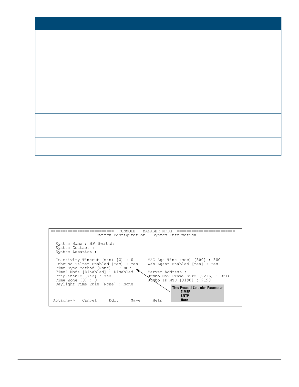
SNTP parameter Operation
Broadcast
Poll Interval
(seconds)
Server Address Used only when the SNTP Mode is set to Unicast. Specifies the IP address of the SNTP
Server Version Specifies the SNTP software version to use and is assigned on a per-server basis. The
Priority Specifies the order in which the configured servers are polled for getting the time. Value is
Directs the switch to acquire its time synchronization from data broadcast by any SNTP
server to the network broadcast address. The switch uses the first server detected and
ignores any others. However, if the Poll Interval expires three times without the switch
detecting a time update from the original server, the switch accepts a broadcast time
update from the next server it detects.
In Unicast Mode: Specifies how often the switch polls the designated SNTP server for a
time update.In Broadcast Mode: Specifies how often the switch polls the network
broadcast address for a time update.Value is between 30 to 720 seconds.
server that the switch accesses for time synchronization updates. You can configure up to
three servers; one using the menu or CLI, and two more using the CLI.
version setting is backwards-compatible. For example, using version 3 means that the
switch accepts versions 1 through 3. Default: 3; range: 1 to 7.
between 1 and 3.
Viewing and configuring SNTP (Menu)
Procedure
1. From the Main Menu, select:
a. 2. Switch Configuration…
b. 1. System Information
Figure 1: System Information screen (default values)
2. Press [E] (for Edit ).
Move the cursor to the System Name field.
3. Use the Space bar to move the cursor to the Time Sync Method field.
4. Use the Space bar to select SNTP, then move to the SNTP Mode field.
28 Aruba 2920 Management and Configuration Guide for
ArubaOS-Switch 16.05
Page 29
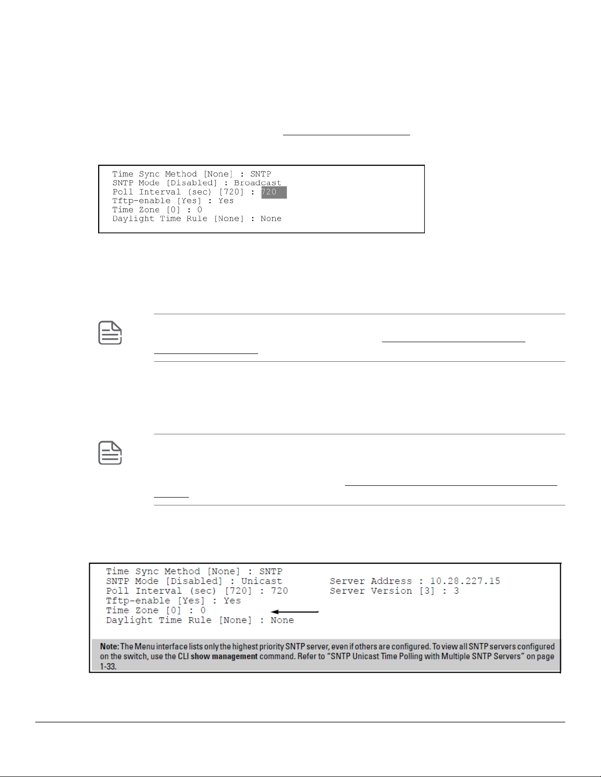
5. Complete one of the following options.
Option 1
a. Use the Space bar to select the Broadcast mode.
b. Move the cursor to the Poll Interval field.
c. Go to 6. (For Broadcast mode details, see SNTP time synchronization)
Figure 2: Time configuration fields for SNTP with broadcast mode
Option 2
d. Use the Space bar to select the Unicast mode.
e. Move the cursor to the Server Address field.
f. Enter the IP address of the SNTP server you want the switch to use for time synchronization.
NOTE: This step replaces any previously configured server IP address. If you will be using
backup SNTP servers (requires use of the CLI), see SNTP unicast time polling with
multiple SNTP servers.
g. Move the cursor to the Server Version field. Enter the value that matches the SNTP server version running
on the device you specified in the preceding step.
If you are unsure which version to use, Hewlett Packard Enterprise recommends leaving this value at the
default setting of 3 and testing SNTP operation to determine whether any change is necessary.
NOTE: Using the menu to enter the IP address for an SNTP server when the switch already
has one or more SNTP servers configured, the switch deletes the primary SNTP server from
the server list. The switch then selects a new primary SNTP server from the IP addresses in
the updated list. For more on this topic, see SNTP unicast time polling with multiple SNTP
servers.
h. Move the cursor to the Poll Interval field, then go to step 6.
Figure 3: SNTP configuration fields for SNTP configured with unicast mode
6. In the Poll Interval field, enter the time in seconds that you want for a Poll Interval.
Chapter 2 Time Protocols 29
Page 30

(For Poll Interval operation, see SNTP parameters)
7. Press Enter to return to the Actions line, then S (for Save) to enter the new time protocol configuration in both
the startup-config and running-config files.
Viewing and configuring SNTP (CLI)
Syntax:
show sntp
Lists both the time synchronization method (TimeP, SNTP, or None) and the SNTP configuration, even if SNTP is
not the selected time protocol.
If you configure the switch with SNTP as the time synchronization method, then enable SNTP in broadcast mode
with the default poll interval, show sntp lists the following:
SNTP configuration when SNTP is the selected time synchronization method
switch(config)# show sntp
SNTP Configuration
Time Sync Mode: Sntp
SNTP Mode : Unicast
Poll Interval (sec) [720] : 719
Priority SNTP Server Address Protocol Version
-------- ------------------------------ ----------------
1 2001:db8::215:60ff:fe79:8980 7
2 10.255.5.24 3
3 fe80::123%vlan10 3
In the factory-default configuration (where TimeP is the selected time synchronization method), show sntp still
lists the SNTP configuration, even though it is not currently in use. In
the selected time synchronization method on page 30, even though TimeP is the current time synchronous
method, the switch maintains the SNTP configuration.
SNTP configuration when SNTP is not the selected time synchronization method
switch(config)# show sntp
SNTP Configuration
Time Sync Mode: Timep
SNTP Mode : Unicast
Poll Interval (sec) [720] : 719
Priority SNTP Server Address Protocol Version
-------- ------------------------------ ----------------
1 2001:db8::215:60ff:fe79:8980 7
2 10.255.5.24 3
3 fe80::123%vlan10 3
SNTP configuration when SNTP is not
Syntax:
show management
30 Aruba 2920 Management and Configuration Guide for
ArubaOS-Switch 16.05
Page 31

This command can help you to easily examine and compare the IP addressing on the switch. It lists the IP
addresses for all time servers configured on the switch, plus the IP addresses and default gateway for all VLANs
configured on the switch.
Display showing IP addressing for all configured time servers and VLANs
switch(config)# show management
Status and Counters - Management Address Information
Time Server Address : fe80::215:60ff:fe7a:adc0%vlan10
Priority SNTP Server Address Protocol Version
--------- ------------------------------ ----------------
1 2001:db8::215:60ff:fe79:8980 7
2 10.255.5.24 3
3 fe80::123%vlan10 3
Default Gateway :10.0.9.80
VLAN Name MAC Address | IP address
------------ --------------- + ---------------
DEFAULT_VLAN 001279-88a100 | Disabled
VLAN10 001279-88a100 | 10.0.10.17
Configuring (enabling or disabling) the SNTP mode
Enabling the SNTP mode means to configure it for either broadcast or unicast mode. Remember that to run SNTP
as the switch's time synchronization protocol, you must also select SNTP as the time synchronization method by
using the CLI timesync command (or the menu interface Time Sync Method parameter.)
Syntax:
timesync sntp
Selects SNTP as the time protocol.
sntp {<broadcast | unicast>}
Enables the SNTP mode.
Syntax:
sntp server <ip-addr>
Required only for unicast mode.
Syntax:
sntp server priority <1-3>
Specifies the order in which the configured servers are polled for getting the time. Value is between 1 and 3.
Syntax:
sntp <30-720>
Configures the amount of time between updates of the system clock via SNTP.
Chapter 2 Time Protocols 31
Page 32

Default: 720 seconds
Enabling SNTP in Broadcast Mode
Because the switch provides an SNTP polling interval (default: 720 seconds), you need only these two commands
for minimal SNTP broadcast configuration:
Syntax:
timesync sntp
Selects SNTP as the time synchronization method.
Syntax:
sntp broadcast
Configures broadcast as the SNTP mode.
Example:
Suppose that time synchronization is in the factory-default configuration (TimeP is the currently selected time
synchronization method.) Complete the following:
Procedure
1. View the current time synchronization.
2. Select SNTP as the time synchronization mode.
3. Enable SNTP for Broadcast mode.
4. View the SNTP configuration again to verify the configuration.
32 Aruba 2920 Management and Configuration Guide for
ArubaOS-Switch 16.05
Page 33

The commands and output would appear as follows:
Figure 4: Enabling SNTP operation in Broadcast Mode
switch(config)# show sntp
1
SNTP Configuration
Time Sync Mode: Timep
SNTP Mode : disabled
Poll Interval (sec) [720] :720
switch(config)# timesync sntp
switch(config)# sntp broadcast
switch(config)# show sntp
2
SNTP Configuration
Time Sync Mode: Sntp
SNTP Mode : Broadcast
Poll Interval (sec) [720] :720
•1show sntp displays the SNTP configuration and also shows that TimeP is the currently
active time synchronization mode.
•2show sntp again displays the SNTP configuration and shows that SNTP is now the
currently active time synchronization mode and is configured for broadcast operation.
Enabling SNTP in unicast mode (CLI)
Like broadcast mode, configuring SNTP for unicast mode enables SNTP. However, for unicast operation, you
must also specify the IP address of at least one SNTP server. The switch allows up to three unicast servers. You
can use the Menu interface or the CLI to configure one server or to replace an existing unicast server with
another. To add a second or third server, you must use the CLI. For more on SNTP operation with multiple
servers, see SNTP unicast time polling with multiple SNTP servers on page 49
Syntax:
timesync sntp
Selects SNTP as the time synchronization method.
Syntax:
sntp unicast
Configures the SNTP mode for unicast operation.
Syntax:
[no] sntp server priority < 1-3 > < ip-address > [version]
Use the no version of the command to disable SNTP.
priority
Specifies the order in which the configured SNTP servers are polled for the time.
Chapter 2 Time Protocols 33
Page 34

ip-address
An IPv4 or IPv6 address of an SNTP server.
version
The protocol version of the SNTP server. Allowable values are 1 through 7; default is 3.
Syntax:
no sntp server priority <1-3> <ip-addr>
Deletes the specified SNTP server.
NOTE:
priority <1-3>
value must match what server is configured with. Deleting an SNTP server when only one is
configured disables SNTP unicast operation.
Example:
To select SNTP and configure it with unicast mode and an SNTP server at 10.28.227.141 with the default server
version (3) and default poll interval (720 seconds):
switch(config)# timesync sntp
Selects SNTP.
switch(config)# sntp unicast
Activates SNTP in unicast mode.
switch(config)# sntp server priority 1 10.28.227.141
Specifies the SNTP server and accepts the current SNTP server version (default: 3).
Configuring SNTP for unicast operation
switch(config)# show sntp
SNTP Configuration
Time Sync Mode: Sntp
SNTP Mode : Unicast
Poll Interval (sec) [720] : 720
Priority SNTP Server Address Protocol Version
-------- ---------------------------------------------- ----------------
1 2001:db8::215:60ff:fe79:8980 7
2 10.255.5.24 3
3 fe80::123%vlan10 3
In this Example:, the Poll Interval and the Protocol Version appear at their default settings.
Both IPv4 and IPv6 addresses are displayed.
Note: Protocol Version appears only when there is an IP address configured for an SNTP server.
If the SNTP server you specify uses SNTP v4 or later, use the sntp server command to specify the correct
version number. For example, suppose you learned that SNTP v4 was in use on the server you specified above
34 Aruba 2920 Management and Configuration Guide for
ArubaOS-Switch 16.05
Page 35

(IP address 10.28.227.141). You would use the following commands to delete the server IP address , re-enter it
with the correct version number for that server.
Specifying the SNTP protocol version number
switch(config)# no sntp server 10.28.227.141
switch(config)# sntp server 10.28.227.141 4
1
2
switch(config)# show sntp
SNTP Configuration
Time Sync Mode: Sntp
SNTP Mode : Broadcast
Poll Interval (sec) [720] : 600
IP Address Protocol Version
------------- -----------------
10.28.227.141 4
3
•1Deletes unicast SNTP server entry.
•2Re-enters the unicast server with a non-default protocol version.
•3show sntp displays the result.
Changing the SNTP poll interval (CLI)
Syntax:
sntp <30..720>
Specifies the amount of time between updates of the system clock via SNTP. The default is 720 seconds and the
range is 30 to 720 seconds. (This parameter is separate from the poll interval parameter used for Timep
operation.)
Example:
To change the poll interval to 300 seconds:
switch(config)# sntp 300
Changing the SNTP server priority (CLI)
You can choose the order in which configured servers are polled for getting the time by setting the server priority.
Syntax:
sntp server priority <1-3> <ip-address>
Specifies the order in which the configured servers are polled for getting the time Value is between 1 and 3.
NOTE: You can enter both IPv4 and IPv6 addresses. For more information about IPv6 addresses,
see the IPv6 configuration guide for your switch.
Example:
To set one server to priority 1 and another to priority 2:
switch(config)# sntp server priority 1 10.28.22.141
Chapter 2 Time Protocols 35
Page 36

switch(config)# sntp server priority 2
2001:db8::215:60ff:fe79:8980
Disabling time synchronization without changing the SNTP configuration (CLI)
The recommended method for disabling time synchronization is to use the timesync command.
Syntax:
no timesync
Halts time synchronization without changing your SNTP configuration.
Example:
Suppose SNTP is running as the switch's time synchronization protocol, with broadcast as the SNTP mode and
the factory-default polling interval. You would halt time synchronization with this command:
switch(config)# no timesync
If you then viewed the SNTP configuration, you would see the following:
SNTP with time synchronization disabled
switch(config)# show sntp
SNTP Configuration
Time Sync Mode: Disabled
SNTP Mode : Broadcast
Poll Interval (sec) [720] : 720
Disabling the SNTP Mode
If you want to prevent SNTP from being used even if it is selected by timesync (or the Menu interface's Time
Sync Method parameter), configure the SNTP mode as disabled.
Syntax:
no sntp
Disables SNTP by changing the SNTP mode configuration to Disabled.
Example:
If the switch is running SNTP in unicast mode with an SNTP server at 10.28.227.141 and a server version of 3
(the default), no sntp changes the SNTP configuration as shown below and disables time synchronization on
the switch.
Disabling time synchronization by disabling the SNTP mode
switch(config)# no sntp
switch(config)# show sntp
SNTP Configuration
Time Sync Mode: Sntp
SNTP Mode : disabled
Poll Interval (sec) [720] : 600
IP Address Protocol Version
------------- -----------------
10.28.227.141 3
36 Aruba 2920 Management and Configuration Guide for
ArubaOS-Switch 16.05
Page 37

Note that even though the Time Sync Mode is set to Sntp, time synchronization is disabled because no sntp
has disabled the SNTP Mode parameter.
SNTP client authentication
Enabling SNTP authentication allows network devices such as HPE switches to validate the SNTP messages
received from an NTP or SNTP server before updating the network time. NTP or SNTP servers and clients must
be configured with the same set of authentication keys so that the servers can authenticate the messages they
send and clients (switches) can validate the received messages before updating the time.
This feature provides support for SNTP client authentication on switches, which addresses security
considerations when deploying SNTP in a network.
Requirements
You must configure the following to enable SNTP client authentication on the switch.
SNTP client authentication support
• Timesync mode must be SNTP. Use the timesync sntp command. (SNTP is disabled by default).
• SNTP must be in unicast or broadcast mode. See
authentication on page 40.
• The MD5 authentication mode must be selected.
• An SNTP authentication key-identifier (key-id) must be configured on the switch and a value (key-value)
must be provided for the authentication key. A maximum of 8 sets of key-id and key-value can be
configured on the switch.
• Among the keys that have been configured, one key or a set of keys must be configured as trusted. Only
trusted keys are used for SNTP authentication.
• If the SNTP server requires authentication, one of the trusted keys has to be associated with the SNTP server.
• SNTP client authentication must be enabled on the HPE Switch. If client authentication is disabled, packets
are processed without authentication.
All of the above steps are necessary to enable authentication on the client.
SNTP server authentication support
NOTE:
SNTP server is not supported on Switch products.
You must perform the following on the SNTP server:
Configuring unicast and broadcast mode for
• The same authentication key-identifier, trusted key, authentication mode and key-value that were configured
on the SNTP client must also be configured on the SNTP server.
• SNTP server authentication must be enabled on the server.
If any of the parameters on the server are changed, the parameters have to be changed on all the SNTP clients in
the network as well. The authentication check fails on the clients otherwise, and the SNTP packets are dropped.
Configuring the key-identifier, authentication mode, and key-value (CLI)
This command configures the key-id, authentication-mode, and key-value, which are required for
authentication. It is executed in the global configuration context.
Chapter 2 Time Protocols 37
Page 38

Syntax:
sntp authentication key-id <key-id> authentication-mode <md5> key-value <key-string> [trusted]
no sntp authentication key-id <key-id>
Configures a key-id, authentication-mode (MD5 only), and key-value, which are required for authentication.
The no version of the command deletes the authentication key.
Default: No default keys are configured on the switch.
key-id
A numeric key identifier in the range of 1-4,294,967,295 (232) that identifies the unique key value. It is sent in
the SNTP packet.
key-value <key-string>
The secret key that is used to generate the message digest. Up to 32 characters are allowed for keystring .
encrypted-key <<key-string>>
Set the SNTP authentication key value using a base64–encoded aes-256 encrypted string.
Setting parameters for SNTP authentication
switch(config)# sntp authentication key-id 55 authentication-mode md5
key-value secretkey1
Configuring a trusted key
Trusted keys are used in SNTP authentication. In unicast mode, you must associate a trusted key with a
specific NTP/SNTP server. That key is used for authenticating the SNTP packet.
In unicast mode, a specific server is configured on the switch so that the SNTP client communicates with the
specified server to get the date and time.
In broadcast mode, the SNTP client switch checks the size of the received packet to determine if it is
authenticated. If the broadcast packet is authenticated, the key-id value is checked to see if the same key-id value
is configured on the SNTP client switch. If the switch is configured with the same key-id value, and the key-id
value is configured as "trusted," the authentication succeeds. Only trusted key-id value information is used for
SNTP authentication. For information about configuring these modes, see Configuring unicast and broadcast
mode for authentication on page 40.
If the packet contains key-id value information that is not configured on the SNTP client switch, or if the received
packet contains no authentication information, it is discarded. The SNTP client switch expects packets to be
authenticated if SNTP authentication is enabled.
When authentication succeeds, the time in the packet is used to update the time on the switch.
Configuring a key-id as trusted (CLI)
Enter the following command to configure a key-id as trusted.
Syntax:
sntp authentication key-id <key-id> trusted
no sntp authentication key-id <key-id> trusted
38 Aruba 2920 Management and Configuration Guide for
ArubaOS-Switch 16.05
Page 39

Trusted keys are used during the authentication process. You can configure the switch with up to eight sets of
key-id/key-value pairs. One specific set must selected for authentication; this is done by configuring the set as
trusted.
The key-id itself must already be configured on the switch. To enable authentication, at least one key-id must
be configured as trusted.
The no version of the command indicates the key is unreliable (not trusted).
Default: No key is trusted by default.
For detailed information about trusted keys, see
Configuring a trusted key on page 38
Associating a key with an SNTP server (CLI)
Syntax:
[no] sntp server priority <1-3> {< ip-address | ipv6-address >} <version-num> [key-id <1-4,294,967,295>]
Configures a key-id to be associated with a specific server. The key itself must already be configured on the
switch.
The no version of the command disassociates the key from the server. This does not remove the authentication
key.
Default: No key is associated with any server by default.
priority
Specifies the order in which the configured servers are polled for getting the time.
version-num
Specifies the SNTP software version to use and is assigned on a per-server basis. The version setting is
backwards-compatible. For example, using version 3 means that the switch accepts versions 1 through 3.
Default: 3; range: 1 - 7.
key-id
Optional command. The key identifier sent in the SNTP packet. This key-id is associated with the SNTP
server specified in the command.
Associating a key-id with a specific server
switch(config)# sntp server priority 1 10.10.19.5 2 key-id 55
Enabling SNTP client authentication
The sntp authentication command enables SNTP client authentication on the switch. If SNTP
authentication is not enabled, SNTP packets are not authenticated.
Syntax:
[no] sntp authentication
Enables the SNTP client authentication.
The no version of the command disables authentication.
Default: SNTP client authentication is disabled.
Chapter 2 Time Protocols 39
Page 40

Configuring unicast and broadcast mode for authentication
To enable authentication, you must configure either unicast or broadcast mode. When authentication is enabled,
changing the mode from unicast to broadcast or vice versa is not allowed; you must disable authentication and
then change the mode.
To set the SNTP mode or change from one mode to the other, enter the appropriate command.
Syntax:
sntp unicast
sntp broadcast
Enables SNTP for either broadcast or unicast mode.
Default: SNTP mode is disabled by default. SNTP does not operate even if specified by the CLI timesync
command or by the menu interface Time Sync Method parameter.
Unicast
Broadcast
Directs the switch to poll a specific server periodically for SNTP time synchronization.The
default value between each polling request is 720 seconds, but can be configured.At least one
manually configured server IP address is required.
NOTE:
At least one key-id must be configured as trusted, and it must be associated with one of the
SNTP servers. To edit or remove the associated key-id information or SNTP server information,
SNTP authentication must be disabled.
Directs the switch to acquire its time synchronization from data broadcast by any SNTP server
to the network broadcast address. The switch uses the first server detected and ignores any
others. However, if the Poll Interval (configurable up to 720 seconds) expires three times
without the switch detecting a time update from the original server, the switch accepts a
broadcast time update from the next server it detects.
Viewing SNTP authentication configuration information (CLI)
The show sntp command displays SNTP configuration information, including any SNTP authentication keys that
have been configured on the switch.
SNTP configuration information
switch(config)# show sntp
SNTP Configuration
SNTP Authentication : Enabled
Time Sync Mode: Sntp
SNTP Mode : Unicast
Poll Interval (sec) [720] : 720
Priority SNTP Server Address Protocol Version KeyId
-------- ------------------------------------ ---------------- -----
1 10.10.10.2 3 55
2 fe80::200:24ff:fec8:4ca8 3 55
40 Aruba 2920 Management and Configuration Guide for
ArubaOS-Switch 16.05
Page 41

Viewing all SNTP authentication keys that have been configured on the switch (CLI)
Enter the show sntp authentication command, as shown in Show sntp authentication command output
on page 41.
Show sntp authentication command output
switch(config)# show sntp authentication
SNTP Authentication Information
SNTP Authentication : Enabled
Key-ID Auth Mode Trusted
------- ---------- --------
55 MD5 Yes
10 MD5 No
Viewing statistical information for each SNTP server (CLI)
To display the statistical information for each SNTP server, enter the show sntp statistics command.
The number of SNTP packets that have failed authentication is displayed for each SNTP server address, as
shown in SNTP authentication statistical information on page 41.
SNTP authentication statistical information
switch(config)# show sntp statistics
SNTP Statistics
Received Packets : 0
Sent Packets : 3
Dropped Packets : 0
SNTP Server Address Auth Failed Pkts
--------------------------------------- ----------------
10.10.10.1 0
fe80::200:24ff:fec8:4ca8 0
Saving configuration files and the include-credentials command
You can use the include-credentials command to store security information in the running-config file. This
allows you to upload the file to a TFTP server and then later download the file to the HPE switches on which you
want to use the same settings. For more information about the include-credentials command, see
"Configuring Username and Password Security" in the access security guide for your switch.
The authentication key values are shown in the output of the show running-config and show config
commands only if the include-credentials command was executed.
When SNTP authentication is configured and include-credentials has not been executed, the SNTP
authentication configuration is not saved.
Configuration file with SNTP authentication information
switch(config) # show config
Startup configuration:
.
.
.
timesync sntp
Chapter 2 Time Protocols 41
Page 42

sntp broadcast
sntp 50
sntp authentication
sntp server priority 1 10.10.10.2.3 key-id 55
sntp server priority 2 fe80::200:24ff:fec8:4ca8 4 key-id 55
NOTE:
SNTP authentication has been enabled and a key-id of 55 has been created.
In this Example:, the include-credentials command has not been executed and is not present in the
configuration file. The configuration file is subsequently saved to a TFTP server for later use. The SNTP
authentication information is not saved and is not present in the retrieved configuration files, as shown in the
following Example:.
Retrieved configuration file when include credentials is not configured
switch(config) # copy tftp startup-config 10.2.3.44 config1
.
.
.
Switch reboots ...
.
Startup configuration
.
.
.
timesync sntp
sntp broadcast
sntp 50 sntp server priority 1 10.10.10.2.3
sntp server priority 2 fe80::200:24ff:fec8:4ca8 4
.
.
.
NOTE:
The SNTP authentication line and the Key-ids are not displayed. You must reconfigure SNTP
authentication.
42 Aruba 2920 Management and Configuration Guide for
ArubaOS-Switch 16.05
Page 43

If include-credentials is configured, the SNTP authentication configuration is saved in the configuration file.
When the show config command is entered, all of the information that has been configured for SNTP
authentication displays, including the key-values.
Figure 5: Saved SNTP Authentication information when include-credentials is configured
TimeP: Selecting and configuring
The following table shows TimeP parameters and their operations.
Table 2: TimeP parameters
TimeP
parameter
Time Sync
Method
TimeP Mode
Disabled TimeP does not operate, even if specified by the Menu interface Time Sync Method
DHCP When TimeP is selected as the time synchronization method, the switch attempts to acquire a
Manual When TimeP is selected as the time synchronization method, the switch attempts to poll the
Operation
Used to select either TIMEP, SNTP, NTP, or None as the time synchronization method.
parameter or the CLI timesync command.
TimeP server IP address via DHCP. If the switch receives a server address, it polls the server
for updates according to the TimeP poll interval. If the switch does not receive a TimeP server
IP address, it cannot perform time synchronization updates.
specified server for updates according to the TimeP poll interval. If the switch fails to receive
updates from the server, time synchronization updates do not occur.
Server
Address
Chapter 2 Time Protocols 43
Used only when the TimeP Mode is set to Manual. Specifies the IP address of the TimeP
server that the switch accesses for time synchronization updates. You can configure one
server.
Page 44

Viewing, enabling, and modifying the TimeP protocol (Menu)
Procedure
1. From the Main Menu, select:
2. Switch Configuration
1. System Information
Figure 6: System Information screen (default values)
2. Press [E] (for Edit).
The cursor moves to the System Name field.
3. Move the cursor to the Time Sync Method field.
4. If TIMEP is not already selected, use the Space bar to select TIMEP, then move to the TIMEP Mode field.
5. Do one of the following:
• Use the Space bar to select the DHCP mode.
◦ Move the cursor to the Poll Interval field.
◦ Go to step 6.
Enabling TIMEP or DHCP
Time Sync Method [None] : TIMEP
TimeP Mode [Disabled] : DHCP
Poll Interval (min) [720] : 720
Time Zone [0] : 0
Daylight Time Rule [None] : None
• Use the Spacebar to select the Manual mode.
44 Aruba 2920 Management and Configuration Guide for
ArubaOS-Switch 16.05
Page 45

◦ Move the cursor to the Server Address field.
◦ Enter the IP address of the TimeP server you want the switch to use for time synchronization.
NOTE: This step replaces any previously configured TimeP server IP address.
◦ Move the cursor to the Poll Interval field, then go to step 6.
6. In the Poll Interval field, enter the time in minutes that you want for a TimeP Poll Interval.
7. Select [Enter] to return to the Actions line, then select [S] (for Save) to enter the new time protocol
configuration in both the startup-config and running-config files.
Viewing the current TimeP configuration (CLI)
Using different show commands, you can display either the full TimeP configuration or a combined listing of all
TimeP, SNTP, and VLAN IP addresses configured on the switch.
Syntax:
show timep
Lists both the time synchronization method (TimeP, SNTP, or None) and the TimeP configuration, even if SNTP is
not the selected time protocol. (If the TimeP Mode is set to Disabled or DHCP, the Server field does not appear.)
If you configure the switch with TimeP as the time synchronization method, then enable TimeP in DHCP mode
with the default poll interval, show timep lists the following:
TimeP configuration when TimeP is the selected Time synchronization method
switch(config)# show timep
Timep Configuration
Time Sync Mode: Timep
TimeP Mode [Disabled] : DHCP Server Address : 10.10.28.103
Poll Interval (min) [720] : 720
If SNTP is the selected time synchronization method, show timep still lists the TimeP configuration even though
it is not currently in use. Even though, in this Example:, SNTP is the current time synchronization method, the
switch maintains the TimeP configuration:
TimeP configuration when TimeP is not the selected time synchronization method
switch(config)# show timep
Timep Configuration
Time Sync Mode: Sntp
TimeP Mode [Disabled] : Manual Server Address : 10.10.28.100
Poll Interval (min) [720] : 720
Syntax:
show management
Chapter 2 Time Protocols 45
Page 46

Helps you to easily examine and compare the IP addressing on the switch. It lists the IP addresses for all time
servers configured on the switch plus the IP addresses and default gateway for all VLANs configured on the
switch.
Display showing IP addressing for all configured time servers and VLANs
switch(config)# show management
Status and Counters - Management Address Information
Time Server Address : 10.10.28.100
Priority SNTP Server Address Protocol Version
-------- ---------------------------------------------- ----------------
1 10.10..28.101 3
2 10.255.5.24 3
3 fe80::123%vlan10 3
Default Gateway : 10.0.9.80
VLAN Name MAC Address | IP Address
------------ ------------------- + -------------------
DEFAULT_VLAN 001279-88a100 | 10.30.248.184
VLAN10 001279-88a100 | 10.0.10.17
Configuring (enabling or disabling) the TimeP mode
Enabling the TimeP mode means to configure it for either broadcast or unicast mode. Remember to run TimeP as
the switch's time synchronization protocol, you must also select TimeP as the time synchronization method by
using the CLI timesync command (or the menu interface Time Sync Method parameter.
Syntax:
timesync timep
Selects TimeP as the time synchronization method.
Syntax:
ip timep {<dhcp | manual>}
Enables the selected TimeP mode.
Syntax:
[no] ip timep
Disables the TimeP mode.
Syntax:
[no] timesync
Disables the time protocol.
Enabling TimeP in manual mode (CLI)
Like DHCP mode, configuring TimeP for manual mode enables TimeP. However, for manual operation, you must
also specify the IP address of the TimeP server. (The switch allows only one TimeP server.)
46 Aruba 2920 Management and Configuration Guide for
ArubaOS-Switch 16.05
Page 47

Syntax:
timesync timep
Selects TimeP.
Syntax:
ip timep manual <ip-addr>
Activates TimeP in manual mode with a specified TimeP server.
Syntax:
no ip timep
Disables TimeP.
Enabling TimeP in DHCP Mode
Because the switch provides a TimeP polling interval (default:720 minutes), you need only these two commands
for a minimal TimeP DHCP configuration:
Syntax:
timesync timep
Selects TimeP as the time synchronization method.
Syntax:
ip timep dhcp
Configures DHCP as the TimeP mode.
For example, suppose:
• Time Synchronization is configured for SNTP.
• You want to:
◦ View the current time synchronization.
◦ Select TimeP as the synchronization mode.
◦ Enable TimeP for DHCP mode.
◦ View the TimeP configuration.
Enabling TimeP in Manual Mode
Like DHCP mode, configuring TimeP for Manual Mode enables TimeP. However, for manual operation, you must
also specify the IP address of the TimeP server. (The switch allows only one TimeP server.) To enable the TimeP
protocol:
Syntax:
timesync timep
Selects TimeP.
Chapter 2 Time Protocols 47
Page 48

Syntax:
ip timep manual <ip-addr>
Activates TimeP in manual mode with a specified TimeP server.
Syntax:
[no] ip timep
Disables TimeP.
NOTE:
To change from one TimeP server to another, you must use the no ip timep command to disable
TimeP mode, the reconfigure TimeP in manual mode with the new server IP address.
Example:
To select TimeP and configure it for manual operation using a TimeP server address of 10.28.227.141 and the
default poll interval (720 minutes, assuming the TimeP poll interval is already set to the default):
switch(config)# timesync time
Selects TimeP.
switch(config)# ip timep manual 10.28.227.141
Activates TimeP in Manual mode.
Configuring TimeP for manual operation
switch(config)# timesync timep
switch(config)# ip timep manual 10.28.227.141
switch(config)# show timep
Timep Configuration
Time Sync Mode: Timep
TimeP Mode : Manual Server Address : 10.28.227.141
Poll Interval (min) : 720
Changing from one TimeP server to another (CLI)
Procedure
1. Use the no ip timep command to disable TimeP mode.
2. Reconfigure TimeP in Manual mode with the new server IP address.
Changing the TimeP poll interval (CLI)
Syntax:
ip timep {< dhcp | manual >} interval <1-9999>
Specifies how long the switch waits between time polling intervals. The default is 720 minutes and the range is 1
to 9999 minutes. (This parameter is separate from the poll interval parameter used for SNTP operation.)
Example:
To change the poll interval to 60 minutes:
48 Aruba 2920 Management and Configuration Guide for
ArubaOS-Switch 16.05
Page 49

switch(config)# ip timep interval 60
Disabling time synchronization without changing the TimeP configuration (CLI)
Syntax:
no timesync
Disables time synchronization by changing the Time Sync Mode configuration to Disabled. This halts time
synchronization without changing your TimeP configuration. The recommended method for disabling time
synchronization is to use the timesync command.
Example:
Suppose TimeP is running as the switch's time synchronization protocol, with DHCP as the TimeP mode, and the
factory-default polling interval. You would halt time synchronization with this command:
switch(config)# no timesync
If you then viewed the TimeP configuration, you would see the following:
TimeP with time synchronization disabled
switch(config)# show timep
Timep Configuration
Time Sync Mode: Disabled
TimeP Mode : DHCP Poll Interval (min): 720
Disabling the TimeP mode
Syntax:
no ip timep
Disables TimeP by changing the TimeP mode configuration to Disabled and prevents the switch from using it as
the time synchronization protocol, even if it is the selected Time Sync Method option.
Example:
If the switch is running TimeP in DHCP mode, no ip timep changes the TimeP configuration as shown below
and disables time synchronization. Even though the TimeSync mode is set to TimeP, time synchronization is
disabled because no ip timep has disabled the TimeP mode parameter.
Disabling time synchronization by disabling the TimeP mode parameter
switch(config)# no ip timep
switch(config)# show timep
Timep Configuration
Time Sync Mode: Timep
TimeP Mode : Disabled
SNTP unicast time polling with multiple SNTP servers
When running SNTP unicast time polling as the time synchronization method, the switch requests a time update
from the server you configured with either the Server Address parameter in the menu interface, or the primary
server in a list of up to three SNTP servers configured using the CLI. If the switch does not receive a response
from the primary server after three consecutive polling intervals, the switch tries the next server (if any) in the list.
Chapter 2 Time Protocols 49
Page 50

If the switch tries all servers in the list without success, it sends an error message to the Event Log and
reschedules to try the address list again after the configured Poll Interval time has expired.
If there are already three SNTP server addresses configured on the switch, and you want to use the CLI to
replace one of the existing addresses with a new one, you must delete the unwanted address before you
configure the new one.
Displaying all SNTP server addresses configured on the switch (CLI)
The System Information screen in the menu interface displays only one SNTP server address, even if the switch
is configured for two or three servers. The CLI show management command displays all configured SNTP
servers on the switch.
How to list all SNTP servers configured on the switch
switch(config)# show management
Status and Counters - Management Address Information
Time Server Address : fe80::215:60ff:fe7a:adc0%vlan10
Priority SNTP Server Address Protocol Version
-------- ---------------------------------------------- ----------------
1 2001:db8::215:60ff:fe79:8980 7
2 10.255.5.24 3
3 fe80::123%vlan10 3
Default Gateway : 10.0.9.80
VLAN Name MAC Address | IP Address
------------ ------------------- + -------------------
DEFAULT_VLAN 001279-88a100 | Disabled
VLAN10 001279-88a100 | 10.0.10.17
Adding and deleting SNTP server addresses
Adding addresses
As mentioned earlier, you can configure one SNTP server address using either the Menu interface or the CLI. To
configure a second and third address, you must use the CLI. To configure the remaining two addresses, you
would do the following:
Creating additional SNTP server addresses with the CLI
switch(config)# sntp server priority <1-3> 2001:db8::215:60ff:fe79:8980
switch(config)# sntp server 10.255.5.24
NOTE: If there are already three SNTP server addresses configured on the switch, and you want to
use the CLI to replace one of the existing addresses with a new one, you must delete the unwanted
address before you configure the new one.
Deleting addresses
Syntax:
no sntp server <ip-addr>
50 Aruba 2920 Management and Configuration Guide for
ArubaOS-Switch 16.05
Page 51

Deletes a server address. If there are multiple addresses and you delete one of them, the switch re-orders the
address priority.
Example:
To delete the primary address in the above Example: and automatically convert the secondary address to primary:
switch(config)# no sntp server 10.28.227.141
Operating with multiple SNTP server addresses configured (Menu)
When you use the Menu interface to configure an SNTP server IP address, the new address writes over the
current primary address, if one is configured.
SNTP messages in the Event Log
If an SNTP time change of more than three seconds occurs, the switch's Event Log records the change. SNTP
time changes of less than three seconds do not appear in the Event Log.
Network Time Protocol (NTP)
All NTP communications use Coordinated Universal Time (UTC). An NTP server usually receives its time from an
authoritative time source, such as a radio clock or an atomic clock attached to a time server, and then distributes
this time across the network. NTP is extremely efficient; no more than one packet per minute is necessary to
synchronize two machines to within a millisecond of each other.
NTP uses a stratum to describe the distance between a network device and an authoritative time source:
• A stratum 1 time server is directly attached to an authoritative time source (such as a radio or atomic clock or a
GPS time source).
• A stratum 2 NTP server receives its time through NTP from a stratum 1 time server.
Before synchronizing, NTP compares the time reported by several network devices and does not synchronize
with one that is significantly different, even if it is a stratum 1.
The security features of NTP can be used to avoid the accidental or malicious setting of incorrect time. One such
mechanism is available: an encrypted authentication mechanism.
Though similar, the NTP algorithm is more complex and accurate than the Simple Network Time Protocol (SNTP).
IMPORTANT: Enabling this feature results in synchronizing the system clock; therefore, it may affect
all sub-systems that rely on system time.
Commands
The following commands allow the user to configure NTP or show NTP configurations.
timesync ntp
This command is used to update the system clock using NTP.
Syntax
timesync ntp
Description
Chapter 2 Time Protocols 51
Page 52

Update the system clock using NTP.
ntp
This command selects the operating mode of the NTP client.
Syntax
ntp [broadcast|unicast]
Options
broadcast
Sets ntp client to operate in broadcast mode.
unicast
Sets ntp client to operate in unicast mode.
Usage
The default mode is broadcast.
[no] ntp
This command disables NTP and removes all NTP configurations on the device.
Syntax
[no] ntp [authentication <key-id>
| broadcast | enable | max-association
<integer> | server
<IP-ADDR> | trap
<trap-name> | unicast]
Description
Disable NTP and removes the entire NTP configuration.
Options
authentication
Configure NTP authentication.
broadcast
Operate in broadcast mode.
enable
Enable/disable NTP.
max-association
Maximum number of Network Time Protocol (NTP) associations.
server
Configure a NTP server to poll for time synchronization.
trap
Enable/disable NTP traps.
unicast
Operate in unicast mode.
52 Aruba 2920 Management and Configuration Guide for
ArubaOS-Switch 16.05
Page 53

Example
switch(config)# no ntp
This will delete all NTP configurations on this device. Continue [y/n]?
ntp enable
This command is used to enable or disable NTP on the switch.
Syntax
ntp enable
Example
switch(config)# ntp
enable Enable/disable NTP.
Description
Enable or disable NTP. Use [no] to disable NTP.
Restrictions
Validation Error/Warning/Prompt
If timeSync is in SNTP or Timep when NTP is enabled.
When timesync is NTP and ntp is enabled and we try to
change timesync to SNTP.
Timesync is not configured to NTP.
Disable NTP before changing timesync to
SNTP or TIMEP
ntp authentication
This command is used for authentication of NTP server by the NTP client.
Syntax
ntp authentication key-id <KEY-ID> [authentication-mode <MODE> key-value <KEYSTRING>] [trusted]
Parameters/Options
key-id <id>
Sets the key-id for the authentication key.
Subcommands
authentication-mode
Sets the NTP authentication mode
key-value <KEY-STRING>
Sets the key-value for the authentication key.
[trusted]
Sets the authentication key as trusted.
Example
Switch(config)# ntp
Authentication Configure NTP authentication.
Chapter 2 Time Protocols 53
Page 54

Switch(config)# ntp authentication
key-id Set the key-id for this authentication key.
Switch(config)# ntp authentication key-id
<1-4294967295> Set the authentication key-id.
Switch(config)# ntp authentication key-id 1
authentication-mode Set the NTP authentication mode.
trusted Set this authentication key as trusted.
Switch(config)# ntp authentication key-id 1
authentication-mode|trusted md5
Authenticate using MD5.
Switch(config)# ntp authentication key-id 1
authentication-mode|trusted md5key-value Set the NTP authentication key.
Switch(config)# ntp authentication key-id 1
authentication-mode|trusted md5 key-value
KEY Enter a string to be set as the NTP authentication key.
ntp authentication key-id
Syntax
ntp authentication key-id
<key-id> [authentication-mode [md5 | sha1]
key-value <key-value>] [trusted]
Description
The NTP client authenticates the NTP server.
Options
authentication-mode
Set the NTP authentication mode.
• md5: Authenticate using MD5.
• sha1: Authenticate using SHA1.
trusted
Set this authentication key as trusted.
ntp max-association
This command is used to configure the maximum number of servers associated with this NTP client.
Syntax
ntp max-association
<number>
54 Aruba 2920 Management and Configuration Guide for
ArubaOS-Switch 16.05
Page 55

Options
max-association <number>
Sets the maximum number of NTP associations.
Description
Configure maximum number of servers associated with the client. Up to eight servers can be configured as the
maximum.
Restrictions
The range for a maximum number of NTP associations is 1–8.
Example
Switch(config)# ntp
max-associations Maximum number of NTP associations.
Switch(config)# ntp max-associations
<1-8> Enter the number.
Restrictions
Validation Error/Warning/Prompt
When the number of configured NTP servers is more
than the max-associations value.
When the max-associations value is less than the (n)
number of configured NTP servers.
The maximum number of NTP servers
allowed is <number>.
Max-associations value cannot be less
than the number of NTP servers
configured.
ntp server
This command is used to configure the NTP servers.
Syntax
[no] ntp server
ntp server <IP-ADDR|IPv6-ADDR> [key <key-id>] [oobm] [max-poll <max-poll-val>][min-poll <min-poll-val>][burst | iburst] [version <1-4>]
Parameters/Options
[no]
Removes the unicast NTP configurations on the device.
Subcommands
IP-ADDR
Sets the IPv4 address of the NTP server.
IPV6-ADDR
Sets the IPv6 address of the NTP server.
oobm
Specifies that the NTP Unicast server is accessible over an OOBM interface.
key <key-id>
Specifies the authentication key.
Chapter 2 Time Protocols 55
Page 56

max-poll <max-poll-val>
Configures the maximum time intervals in power of 2 seconds. Range is 4–17 (e.g., 5 would translate to 2 raised
to 5 or 32).
min-poll <min-poll-val>
Configures the minimum time intervals in seconds. Range is 4–17.
burst
Enables burst mode.
iburst
Enables initial burst mode.
version
Sets version 1–4.
Usage
A maximum of 8 NTP servers can be configured.
Example
switch(config)# ntp
server Allow the software clock to be synchronized by an NTP
time server.
broadcast Operate in broadcast mode.
unicast Operate in unicast mode.
switch(config)# ntp server
IP-ADDR IPv4 address of the NTP server.
IPV6-ADDR IPv6 address of the NTP server.
switch(config)# ntp server <IP-ADDR>
Key Specify the authentication key.
switch(config)# ntp server <IP-ADDR> key key-id
Max-poll Configure the maximum time intervals in seconds.
switch(config)# ntp server <IP-ADDR> key key-id max-poll
<4-17> Enter an integer number.
Switch(config)# ntp server <IP-ADDR> key key-id
Min-poll Configure the minimum time intervals in seconds.
switch(config)# ntp server <IP-ADDR> key key-id min-poll
<4-17> Enter an integer number.
switch(config)# ntp server <IP-ADDR> key key-id prefer max-poll
<max-poll-val> min-poll <min-poll-val>
iburst Enable initial burst (iburst) mode.
burst Enable burst mode.
56 Aruba 2920 Management and Configuration Guide for
ArubaOS-Switch 16.05
Page 57

Switch(config)# ntp server IP-ADDR key key-id prefer maxpoll <number>
minpoll <number> iburst
Restrictions
Validation Error/Warning/Prompt
If authentication key-id not configured
If Key-id is not marked as trusted
When min poll value is more than max poll value
Authentication key-id has not been
configured.
Key-id is not trusted.
NTP max poll value should be more than
min poll value.
ntp server key-id
Syntax
ntp server <IP-ADDR |IPV6-ADDR>
key—id <key-id> [max-poll
<max-poll-val>] [min-poll
<min-poll-val>] [burst | iburst]
Description
Configure the NTP server. <IP-ADDR> indicates the IPv4 address of the NTP server. <IPV6-ADDR> indicates the
IPv6 address of the NTP server.
Options
burst
Enables burst mode.
iburst
Enables initial burst (iburst) mode.
key-id
Set the authentication key to use for this server.
max-poll <max-poll-val>
Configure the maximum time intervals in seconds.
min-poll <min-poll-val>
Configure the minimum time intervals in seconds.
ntp ipv6-multicast
This command is used to configure NTP multicast on a VLAN interface.
Syntax
ntp ipv6-multicast
Description
Configure the interface to listen to the NTP multicast packets.
Example
Switch(vlan-2)# ntp
ipv6-multicast Configure the interface to listen to the NTP multicast packets.
Chapter 2 Time Protocols 57
Page 58

Restrictions
Validation Error/Warning/Prompt
If ipv6 is not enabled on vlan interface
IPv6 address not configured on the
VLAN.
debug ntp
This command is used to display debug messages for NTP.
Syntax
debug ntp <event |
packet>
Options
event
Displays event log messages related to NTP.
packets
Displays NTP packet messages.
Description
Enable debug logging. Use [no] to disable debug logging.
Example
Switch(config)# debug ntp
event Display event log messages related to NTP.
packet Display NTP packet messages.
ntp trap
This command is used to configure NTP traps.
Syntax
ntp trap <trap-name>
Description
Enable NTP traps. Use [no] to disable NTP traps.
Options
ntp-mode-change
Trap name resulting in send notification when the NTP entity changes mode, including
starting and stopping (if possible).
ntp-stratum-change
Trap name resulting in send notification when stratum level of NTP changes.
ntp-peer-change
Trap name resulting in send notification when a (new) syspeer has been selected.
ntp-new-association
Trap name resulting in send notification when a new association is mobilized.
58 Aruba 2920 Management and Configuration Guide for
ArubaOS-Switch 16.05
Page 59

ntp-remove-association
Trap name resulting in send notification when an association is demobilized.
ntp-config-change
Trap name resulting in send notification when the NTP configuration has changed.
ntp-leapsec-announced
Trap name resulting in send notification when a leap second has been announced.
ntp-alive-heartbeat
Trap name resulting in send notification periodically (as defined by
ntpEntHeartbeatInterval) to indicate that the NTP entity is still alive.
all
Enable all traps.
Usage
The traps defined below are generated as the result of finding an unusual condition while parsing an NTP packet
or a processing a timer event. Note that if more than one type of unusual condition is encountered while parsing
the packet or processing an event, only the first one will generate a trap. Possible trap names are:
- 'ntpEntNotifModeChange' The notification to be sent when the NTP entity changes
mode, including starting and stopping (if possible).
- 'ntpEntNotifStratumChange' The notification to be sent when stratum level of NTP
changes.
- 'ntpEntNotifSyspeerChanged' The notification to be sent when a (new) syspeer has
been selected.
- 'ntpEntNotifAddAssociation' The notification to be sent when a new association is
mobilized.
- 'ntpEntNotifRemoveAssociation' The notification to be sent when an association is
demobilized.
- 'ntpEntNotifConfigChanged' The notification to be sent when the NTP configuration
has changed.
- 'ntpEntNotifLeapSecondAnnounced' The notification to be sent when a leap second
has been announced.
- 'ntpEntNotifHeartbeat' The notification to be sent periodically (as defined by
ntpEntHeartbeatInterval) to indicate that the NTP entity is still alive.
- 'ntpEntNotifAll' The notification to be sent when all traps have been enabled
show ntp statistics
This command is used to show NTP statistics.
Syntax
show ntp statistics
Description
Show information about NTP packets.
Examples
Switch(config)# show ntp statistics
Chapter 2 Time Protocols 59
Page 60

NTP Global statistics information
NTP In Packets : 100
NTP Out Packets : 110
NTP Bad Version Packets : 4
NTP Protocol Error Packets : 0
switch(config)# show ntp statistics
NTP Global statistics information
NTP In Packets : 100
NTP Out Packets : 110
NTP Bad Version Packets : 4
NTP Protocol Error Packets : 0
show ntp status
Syntax
Description
Show the status of NTP.
show ntp status
Example
Switch(config)# show ntp status
NTP Status information
NTP Status : Disabled NTP Mode : Broadcast
Synchronization Status : Synchronized Peer Dispersion : 8.01 sec
Stratum Number : 2 Leap Direction : 1
Reference Assoc Id : 1 Clock Offset : 0.0000 sec
Reference : 192.0.2.1 Root Delay : 0.00 sec
Precision : 2**7 Root Dispersion : 15.91 sec
NTP Uptime : 01d 09h 15m Time Resolution : 1
Drift : 0.000000000 sec/sec
System Time : Tue Aug 25 04:59:11 2015
Reference Time : Mon Jan 1 00:00:00 1990
show ntp associations
Syntax
show ntp associations [detail
<IP-ADDR>]
Description
Show the status of configured NTP associations.
Options
detail
Show the detailed status of NTP associations configured for the system.
60 Aruba 2920 Management and Configuration Guide for
ArubaOS-Switch 16.05
Page 61

Switch(config)# show ntp associations
NTP Associations Entries
Address St T When Poll Reach Delay Offset Dispersion
-------------- --- -- ---- ----- ------ ------- ------- ----------
121.0.23.1 16 u - 1024 0 0.000 0.000 0.000
231.45.21.4 16 u - 1024 0 0.000 0.000 0.000
55.21.56.2 16 u - 1024 0 0.000 0.000 0.000
23.56.13.1 3 u 209 1024 377 54.936 -6.159 12.688
91.34.255.216 4 u 132 1024 377 1.391 0.978 3.860
Switch(config)# show ntp associations detail <IP ADDR>
NTP association information
IP address : 172.31.32.2 Peer Mode : Server
Status : Configured, Insane, Invalid Peer Poll Intvl : 64
Stratum : 5 Root Delay : 137.77 sec
Ref Assoc ID : 0 Root Dispersion : 142.75
Association Name : NTP Association 0 Reach : 376
Reference ID : 16.93.49.4 Delay : 4.23 sec
Our Mode : Client Offset : -8.587 sec
Our Poll Intvl : 1024 Precision : 2**19
Dispersion : 1.62 sec
Association In Packets : 60
Association Out Packets : 60
Association Error Packets : 0
Origin Time : Fri Jul 3 11:39:40 2015
Receive Time : Fri Jul 3 11:39:44 2015
Transmit Time : Fri Jul 3 11:39:44 2015
-----------------------------------------------------------------------------
Filter Delay = 4.23 4.14 2.41 5.95 2.37 2.33 4.26 4.33
Filter Offset = -8.59 -8.82 -9.91 -8.42 -10.51 -10.77 -10.13 -10.11
show ntp authentication
Syntax
Description
Show the authentication status and other information about the authentication key.
show ntp authentication
Switch(config)# show ntp authentication
NTP Authentication Information
Key-ID Auth Mode Trusted
-------- ---------- -------
67 md5 yes
7 md5 no
1 sha1 yes
2 sha1 no
Chapter 2 Time Protocols 61
Page 62

Validation rules
Validation Error/Warning/Prompt
If access-list name is not valid. Please enter a valid access-list name.
If the authentication method is being set to
two-factor authentication, various messages
display.
If the authentication method is set to twofactor while installing the public key, a
message displays.
If the username and the key installation user
for that privilege do not match, a message
displays and installation is not allowed.
If both the public key and username/password are not
configured: Public key and username/password should
be configured for a successful two-factor
authentication.
If public key is configured and username is not
configured:
Username and password should be configured for a
successful two-factor authentication.
If the username is configured and public key is not
configured:
Public key should be configured for a successful twofactor authentication.
If “ssh-server” certificate is not installed at the time of
enabling certificate-password authentication:
The “ssh-server” certificate should be installed for a
successful two-factor authentication.
The client public keys without username will not be
considered for the two-factor authentication for the SSH
session.
The username in the key being installed does not
match the username configured on the switch.
This will also happen when the
authentication method is set for two-factor.
If the maximum number of <username : TA
profile> associations is reached for a given
TA profile, a message displays.
If secondary authentication type for twofactor authentication chosen is not "none", a
message displays.
If the authentication method is anything other
than two-factor and the two-factor
authentication method options are set, a
message displays.
Maximum number of username associations with a TA
profile is 10.
Not legal combination of authentication methods.
Not legal combination of authentication methods.
Table Continued
62 Aruba 2920 Management and Configuration Guide for
ArubaOS-Switch 16.05
Page 63

Validation Error/Warning/Prompt
If two-factor authentication is set and user
tries to SSH into another system using ssh
<ip | hostname> command, a message
displays.
If timeSync is in SNTP or Timep when NTP
is enabled.
If timesync is NTP and NTP is enabled and
we try to change timesync to SNTP.
If we try to configure NTP servers more than
the configured max-associations value.
If we have ‘n’ NTP servers configured and
we try to configure a max-associations value
less than (n) number of NTP servers already
configured.
If authentication key-id is not configured. Authentication key-id %d has not been configured.
If key-id is not marked as trusted. Key-id %d is not trusted.
If min poll value is more than max poll value. NTP max poll value should be more than min poll
SSH client is not supported when the two-factor
authentication is enabled.
Timesync is not configured to NTP.
Disable NTP before changing timesync to SNTP or
TIMEP.
The maximum number of NTP servers allowed is 2.
Max-associations value cannot be less than the
number of NTP servers configured.
value.
If ipv6 is not enabled on vlan interface. IPv6 address not configured on the VLAN.
Chapter 2 Time Protocols 63
Page 64

Event log messages
Cause
Event Message
RMON_AUTH_TWO_FACTOR_AUTHEN_STATUS W 01/01/15 18:24:03 03397: auth: %s.
Examples:
W 01/01/15 18:24:03 03397: auth: Public key and
username/password should be configured for the
successful two-factor authentication.
W 01/01/15 18:24:03 03397: auth: Username and
password should be configured for the successful
two-factor authentication.
W 01/01/15 18:24:03 03397: auth: Public key should
be configured for the successful two-factor
authentication.
I 01/01/15 18:24:03 03397: auth: The validation of
certificate of SSH user ‘user1’ is successful.
RMON_SSH_KEY_TWO_FACTOR_EN W 01/01/15 18:24:03 03399: ssh: %s.
Examples:
W 01/01/15 18:24:03 03399: ssh: The client public
keys without username will not be considered for the
two-factor authentication for SSH session.
W 01/01/15 18:24:03 03399: ssh: The privilege level
for the user with the SSH key conflicts with the user
configured.
RMON_SSH_TWO_FACTOR_AUTH_FAIL W 01/01/15 18:24:03 03398: ssh: %s.
Examples:
W 01/01/15 18:24:03 03398: ssh: The two-factor
authentication for SSH session failed due to the
failure in public key authentication.
W 01/01/15 18:24:03 03398: ssh: The two-factor
authentication for SSH session failed due to the
failure in username/password authentication.
W 01/01/15 18:24:03 03398: ssh: The two-factor
authentication for SSH session failed due to the
failure in validating the client certificate.
W 01/01/15 18:24:03 03398: ssh: The two-factor
authentication for SSH session failed as “ssh-server”
certificate is not installed.
When NTP client enabled. NTP client is enabled.
When NTP client disabled. NTP client is disabled.
Table Continued
64 Aruba 2920 Management and Configuration Guide for
ArubaOS-Switch 16.05
Page 65

Event Message
When NTP found a new broadcast server. A new broadcast server at %s.
When system clock was updated with new time. The system clock time was changed by %ld sec %lu
nsec. The new time is %s.
When NTP stratum was updated. The NTP Stratum was changed from %d to %d.
When all NTP associations are cleared. All the NTP server associations are reset.
When server is not reachable. The NTP Server 10.1.1.2 is unreachable. (2 times in
60 seconds)
When MD5/SHA1 authentication failed. The MD5 authentication on the NTP packet failed.
The SHA1 authentication on the NTP packet failed.
Monitoring resources
Displaying current resource usage
To display current resource usage in the switch, enter the following command:
Syntax:
show {<qos | access-list | policy> resources}
Displays the resource usage of the policy enforcement engine on the switch by software feature. For each type of
resource, the amount still available and the amount used by each software feature is shown.
show resources
qosaccess-listopenflowpolicy
Displaying current resource usage shows the resource usage on a switch configured for ACLs, QoS, RADIUSbased authentication, and other features:
The "Rules Used" columns show that ACLs, VT, mirroring, and other features (For example, Management VLAN)
have been configured globally or per-VLAN, because identical resource consumption is displayed for each port
range in the switch. If ACLs were configured per-port, the number of rules used in each port range would be
different.
This output allows you to view current resource usage and, if
necessary, prioritize and reconfigure software features to free
resources reserved for less important features.
Display the same command output and provide different ways to
access task-specific information.
See “Viewing OpenFlow Resources” in the OpenFlow
administrators guide for your switch.
Displaying current resource usage
switch(config)# show access-list resources
Resource usage in Policy Enforcement Engine
Chapter 2 Time Protocols 65
Page 66

| Rules | Rules Used
Ports | Available | ACL | QoS | IDM | Other |
------+-------------+-----+-----+-----+-------|
1-48 | 2006 | 10 | 5 | 0 | 6 |
| Meters | Meters Used
Ports | Available | ACL | QoS | IDM | Other |
------+-------------+-----+-----+-----+-------|
1-48 | 255 | | 5 | | 0 |
| Application |
| Port Ranges | Application Port Ranges Used
Ports | Available | ACL | QoS | IDM | Other |
------+-------------+-----+-----+-----+-------|
1-48 | 31 | 1 | 0 | 0 | 0 |
2 of 16 Policy Engine management resources used.
Key:
ACL = Access Control Lists
QoS = Device & Application Port Priority
IDM = Identity Driven Management
Other = Management VLAN, DHCP Snooping, ARP Protection, RA Guard.
Resource usage includes resources actually in use, or reserved for future
use by the listed feature. Internal dedicated-purpose resources, such as
port bandwidth limits or VLAN QoS priority, are not included.
Viewing information on resource usage
The switch allows you to view information about the current usage and availability of resources in the Policy
Enforcement engine, including the following software features:
• Access control lists (ACL)
• Quality-of-service (QoS), including device and application port priority, ICMP rate-limiting, and QoS policies
• Dynamic assignment of per-port or per-user ACLs and QoS through RADIUS authentication designated as
“IDM”.
• Virus throttling (VT) using connection-rate filtering
• Mirroring policies, including switch configuration as an endpoint for remote intelligent mirroring
• Other features, including:
◦ Management VLAN
◦ DHCP snooping
◦ Dynamic ARP protection
◦ Jumbo IP-MTU
Policy enforcement engine
The policy enforcement engine is thehardware element in the switch that manages QoS, mirroring, and ACL
policies, as well as other software features, using the rules that you configure. Resource usage in the policy
enforcement engine is based on how these features are configured on the switch:
66 Aruba 2920 Management and Configuration Guide for
ArubaOS-Switch 16.05
Page 67

• Resource usage by dynamic port ACLs is determined as follows:
Dynamic port ACLs configured by a RADIUS server for an authenticated client determine the current resource
consumption for this feature on a specified slot. When a client session ends, the resources in use for that client
become available for other uses.
• When the following features are configured globally or per-VLAN, resource usage is applied across all port
groups or all slots with installed modules:
◦ ACLs
◦ QoS configurations that use the following commands:
– QoS device priority (IP address) through the CLI using the qos device-priority command
– QoS application port through the CLI using qos tcp-port or qos udp-port
– VLAN QoS policies through the CLI using service-policy
◦ Management VLAN configuration
◦ DHCP snooping
◦ Dynamic ARP protection
◦ Remote mirroring endpoint configuration
◦ Mirror policies per VLAN through the CLI using monitor service
◦ Jumbo IP-MTU
• When the following features are configured per-port, resource usage is applied only to the slot or port group on
which the feature is configured:
◦ ACLs or QoS applied per-port or per-user through RADIUS authentication
◦ ACLs applied per-port through the CLI using the ip access-group or ipv6 traffic-filter
commands
◦ QoS policies applied per port through the CLI using the service-policy command
◦ Mirror policies applied per-port through the CLI using the monitor all service and service-
policycommands
◦ ICMP rate-limiting through the CLI using the rate-limit icmp command
Usage notes for show resources output
• A 1:1 mapping of internal rules to configured policies in the switch does not necessarily exist. As a result,
displaying current resource usage is the most reliable method for keeping track of available resources. Also,
because some internal resources are used by multiple features, deleting a feature configuration may not
increase the amount of available resources.
• Resource usage includes resources actually in use or reserved for future use by the listed features.
• "Internal dedicated-purpose resources" include the following features:
Chapter 2 Time Protocols 67
Page 68

◦ Per-port ingress and egress rate limiting through the CLI using rate-limit in/out
◦ Per-port or per-VLAN priority or DSCP through the CLI using qos priority or qos dscp
◦ Per protocol priority through the CLI using qos protocol
• The "Available" columns display the resources available for additional feature use.
• The "IDM" column shows the resources used for RADIUS-based authentication.
• "Meters" are used when applying either ICMP rate-limiting or a QoS policy with a rate-limit class action.
When insufficient resources are available
The switch has ample resources for configuring features and supporting RADIUS-authenticated clients (with or
without the optional IDMapplication).
If the resources supporting these features become fully subscribed:
• The current feature configuration, RADIUS-authenticated client sessions, and VT instances continue to
operate normally.
• The switch generates anevent log notice to say that current resources are fully subscribed.
• Currently engaged resources must be released before any of the following actions are supported:
◦ Modifying currently configured ACLs, IDM, VT, and other software features, such as Management VLAN,
DHCP snooping, and dynamic ARP protection.You can modify currently configured classifier-base QoS and
mirroring policies if a policy has not been applied to an interface. However, sufficient resources must be
available when you apply a configured policy to an interface.
◦ Acceptance of new RADIUS-based client authentication requests (displayed as a new resource entry for
IDM).Failure to authenticate a client that presents valid credentials may indicate that insufficient resources
are available for the features configured for the client in the RADIUS server. To troubleshoot, check the
event log.
◦ Throttling or blocking of newly detected clients with high rate-of-connection requests (as defined by the
current VT configuration).The switch continues to generate Event Log notifications (and SNMP trap
notification, if configured) for new instances of high-connection-rate behavior detected by the VT feature.
68 Aruba 2920 Management and Configuration Guide for
ArubaOS-Switch 16.05
Page 69

Chapter 3
Port Status and Configuration
Viewing port status and configuring port parameters
Connecting transceivers to fixed-configuration devices
If the switch either fails to show a link between an installed transceiver and another device or demonstrates errors
or other unexpected behavior on the link, check the port configuration on both devices for a speed and/or duplex
(mode) mismatch.
• To check the mode setting for a port on the switch, use either the Port Status screen in the menu interface or
show interfaces brief in the CLI (see Viewing port status and configuration (CLI)).
• To display information about the transceivers installed on a switch, enter the show tech receivers
command in the CLI (The show tech transceivers command on page 77).
Table 3: Status and parameters for each port type
Status or
parameter
Enabled Yes (default): The port is ready for a network connection.
Status (read-only) Up: The port senses a link beat.
Description
No: The port will not operate, even if properly connected in a network. Use this setting, For
example, if the port needs to be shut down for diagnostic purposes or while you are making
topology changes.
Down: The port is not enabled, has no cables connected, or is experiencing a network error.
For troubleshooting information, see the installation and getting started guide you received
with the switch. See also to Appendix C, "Troubleshooting" (in this manual).
Table Continued
Chapter 3 Port Status and Configuration 69
Page 70

Status or
parameter
Mode The port's speed and duplex (data transfer operation) setting.10/100/1000Base-T
Description
Ports:
• Auto-MDIX (default): Senses speed and negotiates with the port at the other end of the
link for port operation (MDI-X or MDI).To see what the switch negotiates for the auto
setting, use the CLI show interfaces brief command or the 3. Port Status
option under 1. Status and Counters in the menu interface.
• MDI: Sets the port to connect with a PC using a crossover cable (manual mode—applies
only to copper port switches using twisted-pair copper Ethernet cables)
• MDIX: Sets the port to connect with a PC using a straight-through cable (manual mode—
applies only to copper port switches using twisted-pair copper Ethernet cables)
• Auto-10: Allows the port to negotiate between half-duplex (HDx) and full-duplex (FDx)
while keeping speed at 10 Mbps. Also negotiates flow control (enabled or disabled).
Hewlett Packard Enterprise recommends auto-10 for links between 10/100 auto-sensing
ports connected with Cat 3 cabling. (Cat 5 cabling is required for 100 Mbps links.).
• 10HDx:10 Mbps, half-duplex
• 10FDx: 10 Mbps, full-duplex
• Auto-100: Uses 100 Mbps and negotiates with the port at the other end of the link for
other port operation features.
• Auto-10-100: Allows the port to establish a link with the port at the other end at either
10 Mbps or 100 Mbps, using the highest mutual speed and duplex mode available. Only
these speeds are allowed with this setting.
• Auto-1000: Uses 1000 Mbps and negotiates with the port at the other end of the link for
other port operation features.
• 100Hdx: Uses 100 Mbps, half-duplex.
• 100Fdx: Uses 100 Mbps, full-duplex
Gigabit Fiber-Optic Ports (Gigabit-SX, Gigabit-LX, and Gigabit-LH):
• 1000FDx: 1000 Mbps (1 Gbps), full-duplex only
• Auto (default): The port operates at 1000FDx and auto-negotiates flow control with the
device connected to the port.
Gigabit Copper Ports:
• 1000FDx: 1000 Mbps (1 Gbps), full-duplex only
• Auto (default): The port operates at 1000FDx and auto-negotiates flow control with the
device connected to the port.
Table Continued
70 Aruba 2920 Management and Configuration Guide for
ArubaOS-Switch 16.05
Page 71

Status or
parameter
Auto-MDIX The switch supports Auto-MDIX on 10Mb, 100Mb, and 1 Gb T/TX (copper) ports. (Fiber
Description
10-Gigabit CX4 Copper Ports:
Auto: The port operates at 10 gigabits FDx and negotiates flow control. Lower speed
settings or half-duplex are not allowed.
10-Gigabit SC Fiber-Optic Ports (10-GbE SR, 10-GbE LR, 10-GbE ER):
Auto: The port operates at 10 gigabits FDx and negotiates flow control. Lower speed
settings or half-duplex are not allowed.
NOTE: Conditioning patch cord cables are not supported on 10-GbE.
ports and 10-gigabit ports do not use this feature.)
• Automdix: Configures the port for automatic detection of the cable type (straightthrough or crossover).
• MDI: Configures the port to connect to a switch, hub, or other MDI-X device with a
straight-through cable.
• MDIX: Configures the port to connect to a PC or other MDI device with a straight-through
cable.
Flow control
Broadcast limit Specifies the percentage of the theoretical maximum network bandwidth that can be used
• Disabled (default): The port does not generate flow control packets, and drops any flow
control packets it receives.
• Enabled: The port uses 802.3x link layer flow control, generates flow-control packets,
and processes received flow-control packets.
With the port mode set to Auto (the default) and flow control enabled, the switch negotiates
flow control on the indicated port. If the port mode is not set to Auto, or if flow control is
disabled on the port, flow control is not used. Note that flow control must be enabled on both
ends of a link.
for broadcast traffic. Any broadcast traffic exceeding that limit will be dropped. Zero (0)
means the feature is disabled.
The broadcast-limit command operates at the port context level to set the broadcast limit for
a port on the switch.
NOTE: This feature is not appropriate for networks that require high levels of
IPX or RIP broadcast traffic.
Viewing port configuration (Menu)
The menu interface displays the configuration for ports and (if configured) any trunk groups.
Chapter 3 Port Status and Configuration 71
Page 72

From the Main Menu, select:
1. Status and Counters 4. Port Status
A switch port status screen
==========================- CONSOLE - MANAGER MODE -==========================
Status and Counters - Port Status
Intrusion MDI Flow Bcast
Port Type Alert Enabled Status Mode Mode Ctrl Limit
----- --------- --------- ------- ------ ---------- ----- ----- ----- 1 100/1000T No Yes Down 100FDx Auto off 0
2 100/1000T No Yes Down 1000FDx Auto off 0
3 100/1000T No Yes Down 1000FDx Auto off 0
4 100/1000T No Yes Down 1000FDx Auto off 0
5 100/1000T No Yes Down 1000FDx Auto off 0
6 100/1000T No Yes Down 1000FDx Auto off 0
7 100/1000T No Yes Down 1000FDx Auto off 0
8 100/1000T No Yes Down 1000FDx Auto off 0
9 100/1000T No Yes Down 1000FDx Auto off 0
10 100/1000T No Yes Down 1000FDx Auto off 0
11 100/1000T No Yes Down 1000FDx Auto off 0
Actions-> Back Intrusion log Help
Return to previous screen.
Use up/down arrow keys to scroll to other entries, left/right arrow keys to
change action selection, and <Enter> to execute action.
Configuring ports (Menu)
The menu interface uses the same screen for configuring both individual ports and port trunk groups. For
information on port trunk groups, see the chapter on "Port Trunking".
Procedure
1. From the Main Menu, select:
2. Switch Configuration…
2. Port/Trunk Settings
Port/trunk settings with a trunk group configured
=====================- TELNET - MANAGER MODE -=====================
Switch Configuration - Port/Trunk Settings
Port Type Enabled Mode Flow Ctrl Group Type
---- -------- + -------- ----------- --------- ----- ---- A1 1000T | Yes Auto-10-100 Disable
A2 1000T | Yes Auto-10-100 Disable
A3 1000T | Yes Auto Disable
A3 1000T | Yes Auto Disable
A4 1000T | Yes Auto Disable
A5 1000T | Yes Auto Disable
A6 1000T | Yes Auto Disable
A7 1000T | Yes Auto Disable Trk1 Trunk
A8 1000T | Yes Auto Disable Trk2 Trunk
Actions-> Cancel Edit Save Help
72 Aruba 2920 Management and Configuration Guide for
ArubaOS-Switch 16.05
Page 73

Cancel changes and return to previous screen.
Use arrow keys to change action selection and <Enter> to execute
action.
2. Press [E] (for Edit).
The cursor moves to the Enabled field for the first port.
For further information on configuration options for these features, see the online help provided with this
screen.
3. When you have finished making changes to the above parameters, press [Enter], then press [S] (for
Save).
Viewing port status and configuration (CLI)
Use the following commands to display port status and configuration data.
Syntax:
show interfaces [brief | config | < port-list >]
brief
Lists the current operating status for all ports on the switch.
config
Lists a subset of configuration data for all ports on the switch; that is, for each port, the display shows whether
the port is enabled, the operating mode, and whether it is configured for flow control.
<port-list>
Shows a summary of network traffic handled by the specified ports.
The show interfaces brief command listing
switch(config)# show interfaces brief
Status and Counters - Port Status
| Intrusion MDI Flow Bcast
Port Type | Alert Enabled Status Mode Mode Ctrl Limit
----- --------- + --------- ------- ------ ---------- ----- ----- ------
B1 100/1000T | No Yes Down Auto-10-100 Auto off 0
B2 100/1000T | No Yes Down 1000FDx Auto off 0
B3 100/1000T | No Yes Down 1000FDx Auto off 0
B4 100/1000T | No Yes Down 1000FDx Auto off 0
B5 100/1000T | No Yes Down 1000FDx Auto off 0
B6 100/1000T | No Yes Down 1000FDx Auto off 0
The show interfaces config command listing
switch(config)# show interfaces config
Port Settings
Port Type | Enabled Mode Flow Ctrl MDI
----- --------- + ------- ------------ --------- ----
B1 100/1000T | Yes Auto-10-100 Disable Auto
B2 100/1000T | Yes Auto Disable Auto
B3 100/1000T | Yes Auto Disable Auto
Chapter 3 Port Status and Configuration 73
Page 74

B4 100/1000T | Yes Auto Disable Auto
B5 100/1000T | Yes Auto Disable Auto
B6 100/1000T | Yes Auto Disable Auto
Dynamically updating the show interfaces command (CLI/Menu)
Syntax:
show interfaces display
Uses the display option to initiate the dynamic update of the show interfaces command, with the output
being the same as the show interfaces command.
NOTE: Select Back to exit the display.
Example:
switch# show interfaces display
When using the display option in the CLI, the information stays on the screen and is updated every 3 seconds, as
occurs with the display using the menu feature. The update is terminated with Cntl-C.
You can use the arrow keys to scroll through the screen when the output does not fit in one screen.
Figure 7: show interfaces display command with dynamically updating output
Customizing the show interfaces command (CLI)
You can create show commands displaying the information that you want to see in any order you want by using
the custom option.
Syntax:
show interfaces custom [port-list] column-list
Select the information that you want to display. Supported columns are shown in the table below.
74 Aruba 2920 Management and Configuration Guide for
ArubaOS-Switch 16.05
Page 75

Table 4: Supported columns, what they display, and examples:
Parameter column Displays Examples
port Port identifier A2
type Port type 100/1000T
status Port status up or down
speed Connection speed and duplex 1000FDX
mode Configured mode auto, auto-100, 100FDX
mdi MDI mode auto, MDIX
flow Flow control on or off
name Friendly port name
vlanid The vlan id this port belongs to, or "tagged" if it
belongs to more than one vlan
enabled port is or is not enabled yes or nointrusion
intrusion Intrusion alert status no
bcast Broadcast limit 0
The custom show interfaces command
switch(config)# show int custom 1-4 port name:4 type vlan intrusion speed enabled mdi
Status and Counters - Custom Port Status
Intrusion
Port Name Type VLAN Alert Speed Enabled MDI-mode
---- ---------- ---------- ----- --------- ------- ------- --------
1 Acco 100/1000T 1 No 1000FDx Yes Auto
2 Huma 100/1000T 1 No 1000FDx Yes Auto
3 Deve 100/1000T 1 No 1000FDx Yes Auto
4 Lab1 100/1000T 1 No 1000FDx Yes Auto
You can specify the column width by entering a colon after the column name, then indicating the number of
characters to display. In the above example, the Name column displays only the first four characters of the name.
All remaining characters are truncated.
4tagged
NOTE: Each field has a fixed minimum width to be displayed. If you specify a field width smaller than
the minimum width, the information is displayed at the minimum width. For example, if the minimum
width for the Name field is 4 characters and you specify Name:2, the Name field displays 4
characters.
You can enter parameters in any order. There is a limit of 80 characters per line; if you exceed this limit an error
displays.
Chapter 3 Port Status and Configuration 75
Page 76

Error messages associated with the show interfaces command
The following table provides information on error messages associated with the show interfaces custom
command.
Error Error message
Requesting too many fields (total characters exceeds
80)
Field name is misspelled Invalid input: <input>
Mistake in specifying the port list Module not present for port or invalid port: <input>
The port list is not specified Incomplete input: custom
Total length of selected data exceeds one line
Note on using pattern matching with the show interfaces custom command
If you have included a pattern matching command to search for a field in the output of the show int custom
command, and the show int custom command produces an error, the error message may not be visible and
the output is empty. For example, if you enter a command that produces an error (such as vlan is misspelled) with
the pattern matching include option, the output may be empty:
HP Switch(config)# show int custom 1-3 name vlun | include vlan1
It is advisable to try the show int custom command first to ensure there is output, and then enter the
command again with the pattern matching option.
Note that in the above command, you can substitute int for interface; that is: show int custom.
Viewing port utilization statistics (CLI)
Use the show interface port-utilization command to view a real-time rate display for all ports on the
switch. The example below shows a sample output from this command.
A show interface port-utilization command listing
switch(config)# show interfaces port-utilization
Status and Counters - Port Utilization
Rx Tx
Port Mode | -------------------------- | ------------------------- | Kbits/sec Pkts/sec Util | Kbits/sec Pkts/sec Util
----- -------- + ---------- --------- ----- + ---------- --------- -----
B1 1000FDx | 0 0 0 | 0 0 0
B2 1000FDx | 0 0 0 | 0 0 0
B3 1000FDx | 0 0 0 | 0 0 0
B4 1000FDx | 0 0 0 | 0 0 0
B5 1000FDx | 0 0 0 | 0 0 0
B6 1000FDx | 0 0 0 | 0 0 0
B7 100FDx | 624 86 00.62 | 496 0 00.49
76 Aruba 2920 Management and Configuration Guide for
ArubaOS-Switch 16.05
Page 77

Operating notes for viewing port utilization statistics
• For each port on the switch, the command provides a real-time display of the rate at which data is received
(Rx) and transmitted (Tx) in terms of kilobits per second (KBits/s), number of packets per second (Pkts/s), and
utilization (Util) expressed as a percentage of the total bandwidth available.
• The show interfaces <port-list> command can be used to display the current link status and the port
rate average over a 5 minute period. Port rates are shown in bits per second (bps) for ports up to 1 Gigabit; for
10 Gigabit ports, port rates are shown in kilobits per second (Kbps).
Viewing transceiver status (CLI)
The show interfaces transceivers command allows you to:
• Remotely identify transceiver type and revision number without having to physically remove an installed
transceiver from its slot.
• Display real-timestatus information about all installed transceivers, including non-operational transceivers.
The example shows sample output from the show tech transceivers command.
NOTE: Part # column below enables you to determine the manufacturer for a specified transceiver
and revision number.
The show tech transceivers command
switch# show tech transceivers
Transceiver Technical Information:
Port # | Type | Prod # | Serial # | Part #
-------+-----------+--------+------------------+----------
21 | 1000SX | J4858B | CN605MP23K |
22 | 1000LX | J4859C | H11E7X | 2157-2345
23 | ?? | ?? | non operational |
25 | 10GbE-CX4 | J8440A | US509RU079 |
26 | 10GbE-CX4 | J8440A | US540RU002 |
27 | 10GbE-LR | J8437B | PPA02-2904:0017 | 2157-2345
28 | 10GbE-SR | J8436B | 01591602 | 2158-1000
29 | 10GbE-ER | J8438A | PPA03-2905:0001 |
The following transceivers may not function correctly:
Port # Message
-------- ------------------------
Port 23 Self test failure.
Operating Notes
The following information is displayed for each installed transceiver:
• Port number on which transceiver is installed.
• Type of transceiver.
• Product number — Includes revision letter, such as A, B, or C. If no revision letter follows a product number,
this means that no revision is available for the transceiver.
• Part number — Allows you to determine the manufacturer for a specified transceiver and revision number.
Chapter 3 Port Status and Configuration 77
Page 78

• For a non-HPE switches installed transceiver (see line 23 of "The show tech transceivers command"
example), no transceiver type, product number, or part information is displayed. In the Serial Number field,
non-operational is displayed instead of a serial number.
• The following error messages may be displayed for a non-operational transceiver:
◦ Unsupported Transceiver. (SelfTest Err#060)
◦ This switch only supports revision B and above transceivers.
◦ Self test failure.
◦ Transceiver type not supported in this port.
◦ Transceiver type not supported in this software version.
◦ Not an HPE Switch Transceiver.
Enabling or disabling ports and configuring port mode (CLI)
You can configure one or more of the following port parameters.
See Status and parameters for each port type.
Syntax:
[no] interface <port-list> [<disable|enable>]
Disables or enables the port for network traffic. Does not use the no form of the command. (Default: enable.)
speed-duplex [<auto-10|10-full|10-half|100-full|100-half|auto|auto-100|1000-full>]
Note that in the above Syntax:, you can substitute int for interface (for example, int <port-list> ).
Specifies the port's data transfer speed and mode. Does not use the no form of the command. (Default: auto.)
The 10/100 auto-negotiation feature allows a port to establish a link with a port at the other end at either 10 Mbps
or 100 Mbps, using the highest mutual speed and duplex mode available. Only these speeds are allowed with this
setting.
Examples:
To configure port C5 for auto-10-100, enter this command:
switch(config)# int c5 speed-duplex auto-10-100
To configure ports C1 through C3 and port C6 for 100Mbps full-duplex, enter these commands:
switch(config)# int c1-c3,c6 speed-duplex 100-full
Similarly, to configure a single port with the above command settings, you could either enter the same command
with only the one port identified or go to the context level for that port and then enter the command. For example,
to enter the context level for port C6 and then configure that port for 100FDx:
switch(config)# int e c6
switch(eth-C6)# speed-duplex 100-full
78 Aruba 2920 Management and Configuration Guide for
ArubaOS-Switch 16.05
Page 79

If port C8 was disabled, and you wanted to enable it and configure it for 100FDx with flow-control active, you
could do so with either of the following command sets:
Figure 8: Two methods for changing a port configuration
For more on flow control, see Enabling or disabling flow control (CLI) on page 79.
Enabling or disabling flow control (CLI)
NOTE: You must enable flow control on both ports in a given link. Otherwise, flow control does not
operate on the link and appears as Off in the show interfaces brief port listing, even if flow
control is configured as enabled on the port in the switch. (See The show interfaces brief
command listing example.) Also, the port (speed-duplex) mode must be set to Auto (the default).
To disable flow control on some ports, while leaving it enabled on other ports, just disable it on the individual ports
you want to exclude.
(You can find more information on flow control in the Status and parameters for each port type table.)
Syntax:
[no] interface <port-list> flow-control
Enables or disables flow control packets on the port. The no form of the command disables flow control on the
individual ports. (Default: Disabled.)
Examples:
Suppose that:
1. You want to enable flow control on ports A1-A6.
2. Later, you decide to disable flow control on ports A5 and A6.
3. As a final step, you want to disable flow control on all ports.
Chapter 3 Port Status and Configuration 79
Page 80

Assuming that flow control is currently disabled on the switch, you would use these commands:
Figure 9: Configuring flow control for a series of ports
switch(config)# int a1-a6 flow-control
switch(config)# show interfaces brief
Status and Counters - Port Status
| Intrusion MDI Flow Bcast
Port Type | Alert Enabled Status Mode Mode Ctrl Limit
------ --------- + --------- ------- ------ ---------- ---- ---- -----
A1 10GbE-T | No Yes Up 1000FDx NA on 0
A2 10GbE-T | No Yes Up 10GigFD NA on 0
A3 10GbE-T | No Yes Up 10GigFD NA on 0
A4 10GbE-T | No Yes Up 10GigFD NA on 0
A5 10GbE-T | No Yes Up 10GigFD NA on 0
A6 10GbE-T | No Yes Up 10GigFD NA on 0
A7 10GbE-T | No Yes Down 10GigFD NA off 0
A8 10GbE-T | No Yes Up 10GigFD NA off 0
switch(config)# no int a5-a6 flow-control
switch(config)# show interfaces brief
Status and Counters - Port Status
| Intrusion MDI Flow Bcast
Port Type | Alert Enabled Status Mode Mode Ctrl Limit
------ --------- + --------- ------- ------ ---------- ---- ---- -----
A1 10GbE-T | No Yes Up 1000FDx NA on 0
A2 10GbE-T | No Yes Down 10GigFD NA on 0
A3 10GbE-T | No Yes Down 10GigFD NA on 0
A4 10GbE-T | No Yes Down 10GigFD NA on 0
A5 10GbE-T | No Yes Down 10GigFD NA off 0
A6 10GbE-T | No Yes Down 10GigFD NA off 0
A7 10GbE-T | No Yes Down 10GigFD NA off 0
A8 10GbE-T | No Yes Down 10GigFD NA off 0
switch(config)# no int a1-a4 flow-control
switch(config)# show interfaces brief
Status and Counters - Port Status
| Intrusion MDI Flow Bcast
Port Type | Alert Enabled Status Mode Mode Ctrl Limit
------ --------- + --------- ------- ------ ---------- ---- ---- -----
A1 10GbE-T | No Yes Down 1000FDx NA off 0
A2 10GbE-T | No Yes Down 10GigFD NA off 0
A3 10GbE-T | No Yes Down 10GigFD NA off 0
A4 10GbE-T | No Yes Down 10GigFD NA off 0
A5 10GbE-T | No Yes Down 10GigFD NA off 0
A6 10GbE-T | No Yes Down 10GigFD NA off 0
A7 10GbE-T | No Yes Down 10GigFD NA off 0
A8 10GbE-T | No Yes Down 10GigFD NA off 0
80 Aruba 2920 Management and Configuration Guide for
ArubaOS-Switch 16.05
Page 81

Port shutdown with broadcast storm
A LAN broadcast storm arises when an excessively high rate of broadcast packets flood the LAN. Occurrence of
LAN broadcast storm disrupts traffic and degrades network performance. To prevent LAN traffic from being
disrupted, an enhancement of fault-finder commands adds new options, and the corresponding MIBs, that trigger
a port disablement when a broadcast storm is detected on that port.
Under this enhancement, the CLI commands given only supports broadcast traffic and not multicast and unicast
types of traffic.
The waiting period range for re-enabling ports is 0 to 604800 seconds. The default waiting period to re-enable a
port is zero which prevents the port from automatic re-enabling.
NOTE: Avoid port flapping when choosing the waiting period by considering the time to re-enable
carefully.
Use the following commands to configure the broadcast-storm on a port.
Syntax:
[no] fault-finder broadcast-storm [ethernet] <port-list> action [warn|warn-and-disable <seconds>] [percent <percent>|pps <rate>]
To remove the current configuration of broadcast-storm on a port, use:
Syntax:
no fault-finder broadcast-storm [ethernet] <port-list>
broadcast-storm
Configure broadcast storm control.
pps
Rising threshold level in number of broadcast packets per second.
percent
Rising threshold level as a percentage of bandwidth of the port. The percentage is calculated on 64 byte
packet size.
warn
Log the event only.
warn-and-disable
Log the event and disable the port.
seconds
Re-enable the port after waiting for the specified number of seconds. Default is not to re-enable.
Configuration examples:
switch(config)# fault-finder broadcast-storm [ethernet] <A1> action [warn-and-disable <65535>]< percent 10>
switch(config)# fault-finder broadcast-storm [ethernet] <A2> action [warn-and-disable <pps 100>
switch(config)# fault-finder broadcast-storm [ethernet] <A22> action [warn] <pps 100>
Viewing broadcast storm
Use the following command to display the broadcast-storm-control configuration.
Chapter 3 Port Status and Configuration 81
Page 82

Syntax:
show fault-finder broadcast-storm [[ethernet] port-list]
Examples:
switch# show fault-finder broadcast-storm [A1]
Port Bcast Storm Port Status Rising
Threshold
A1 Yes Down 10% warn-and-
switch (config)# show fault-finder broadcast-storm
Port Bcast Storm Port Status Rising
Threshold
A1 Yes Down 200 pps warn-and-
switch (config)# show fault-finder broadcast-storm A1
Port Bcast Storm Port Status Rising
Threshold
A1 No Up — none — —
switch (config)# show fault-finder broadcast-storm
Action Disable
Timer
65535 —
disable
Action Disable
Timer
10 9
disable
Action Disable
Timer
Disable
Timer Left
Disable
Timer Left
Disable
Timer Left
Port Bcast Storm Port Status Rising
Threshold
A1 Yes Up 75% warn — —
Action Disable
Timer
Disable
Timer Left
SNMP MIB
SNMP support will be provided through the following MIB objects:
hpicfFfBcastStormControlPortConfig OBJECT IDENTIFIER
:: = { hpicfFaultFinder 5 }
hpicfFfBcastStormControlPortConfigTable OBJECT-TYPE
• syntax sequence: HpicfFfBcastStormControlPortConfigEntry
• max-access: not-accessible
• status: current
• description: This table provides information about broadcast storm control configuration of all ports.::=
{hpicfFfBcastStormControlPortConfig 1}
hpicfFfBcastStormControlPortConfigEntry OBJECT-TYPE
82 Aruba 2920 Management and Configuration Guide for
ArubaOS-Switch 16.05
Page 83

• syntax HpicfFfBcastStormControlPortConfigEntry
• max-access: not-accessible
• status: current
• description: This object provides information about broadcast storm control configuration of each port.
• index: {hpicfffbcaststormcontrolportindex}::= {hpicfFfBcastStormControlPortConfigTable 1}
hpicfFfBcastStormControlPortConfigEntry ::=
Syntax sequence:hpicfFfBcastStormControlPortIndex InterfaceIndex,
hpicfFfBcastStormControlMode Integer,
hpicfFfBcastStormControlRisingpercent Integer32,
hpicfFfBcastStormControlRisingpps Integer32,
hpicfFfBcastStormControlAction Integer,
hpicfFfBcastStormControlPortDisableTimer Unsigned32
hpicfFfBcastStormControlPortIndex OBJECT-TYPE
• Syntax: Interfaceindex
• max-access: not-accessible
• status: current
• description: The Index Value Which Uniquely Identifies A Row In The Interfaces Table.
::= {hpicfFfBcastStormControlPortConfigEntry 1}
hpicfFfBcastStormControlMode OBJECT-TYPE
• Syntax Integer: disabled(1), Bcastrisinglevelpercent(2), Bcastrisinglevelpps(3)
• max-access: read-write
• status: current
• description: The broadcast storm control mode of a port. A value of disable (1) indicates that no rising
threshold value is set for broadcast storm traffic on this port. A value of bcastrisinglevelpercent (2) indicates
that the rising threshold rate for broadcast storm traffic is configured in percentage of port bandwidth. A value
of bcastrisinglevelpps (3) indicates that the rising threshold rate for broadcast storm traffic is configured in
packets per second.
• DEFVAL: disabled
::= {hpicfFfBcastStormControlPortConfigEntry 2}
hpicfFfBcastStormControlRisingpercent OBJECT-TYPE
• Syntax Integer32 (1..100)
• max-access: read-write
Chapter 3 Port Status and Configuration 83
Page 84

• status: current
• description: This Is The Rising Threshold Level in percent of bandwidth of the port.
hpicfFfBcastStormControlAction occurs when broadcast traffic reaches this level.
::= {hpicfFfBcastStormControlPortConfigEntry 3}
hpicfFfBcastStormControlRisingpps OBJECT-TYPE
• Syntax Integer32 (1..10000000)
• max-access: read-write
• status: current
• description: This object indicates the rising threshold for broadcast storm control. This value is in packets-persecond of received broadcast traffic. hpicfffbcaststormcontrolaction object takes action when broadcast
traffic reaches this level.
::= {hpicfFfBcastStormControlPortConfigEntry 4}
hpicfFfBcastStormControlAction OBJECT-TYPE
• Syntax integer: none(1), warn(2), warnanddisable(3)
• max-access: read-write
• status: current
• Description: This object defines the action taken by the switch when a broadcast storm occurs on a port. A
value of none (1) indicates that no action is performed. A value of warn (2) indicates that an event is logged
when broadcast traffic crosses the threshold value set on that port. A value of warn-and-disable (3) indicates
that the port is disabled and an event is logged as soon as the broadcast traffic reaches the threshold value
set on that port.
• DEFVAL: none
::= {hpicfFfBcastStormControlPortConfigEntry 5}
hpicfFfBcastStormControlPortDisableTimer OBJECT-TYPE
• Syntax Unsigned32 (0..604800)
• Units: seconds
• max-access: read-write
• status: current
• Description: This object specifies the time period for which the port remains in disabled state. A port is disabled
when broadcast traffic reaches the threshold value set on that port. This time period is specified in seconds.
The default value is zero which means that the port remains disabled and is not enabled again.
• DEFVAL {0}
::= {hpicfFfBcastStormControlPortConfigEntry 6}
84 Aruba 2920 Management and Configuration Guide for
ArubaOS-Switch 16.05
Page 85

Configuring auto-MDIX
Copper ports on the switch can automatically detect the type of cable configuration (MDI or MDI-X) on a
connected device and adjust to operate appropriately.
This means you can use a "straight-through" twisted-pair cable or a "crossover" twisted-pair cable for any of the
connections—the port makes the necessary adjustments to accommodate either one for correct operation. The
following port types on your switch support the IEEE 802.3ab standard, which includes the "Auto MDI/MDI-X"
feature:
• 10/100-TX xl module ports
• 100/1000-T xl module ports
• 10/100/1000-T xl module ports
Using the above ports:
• If you connect a copper port using a straight-through cable on a switch to a port on another switch or hub that
uses MDI-X ports, the switch port automatically operates as an MDI port.
• If you connect a copper port using a straight-through cable on a switch to a port on an end node—such as a
server or PC—that uses MDI ports, the switch port automatically operates as an MDI-X port.
Auto-MDIX was developed for auto-negotiating devices, and was shared with the IEEE for the development of the
IEEE 802.3ab standard. Auto-MDIX and the IEEE 802.3ab Auto MDI/MID-X feature are completely compatible.
Additionally, Auto-MDIX supports operation in forced speed and duplex modes.
For more information on this subject, see the IEEE 802.3ab standard reference. For more information on MDI-X,
the installation and getting started guide for your switch.
Manual override
If you require control over the MDI/MDI-X feature, you can set the switch to either of these non-default modes:
• Manual MDI
• Manual MDI-X
The table below shows the cabling requirements for the MDI/MDI-X settings.
Table 5: Cable types for auto and manual MDI/MDI-X settings
Setting MDI/MDI-X device type
PC or other MDI device type Switch, hub, or other MDI-X device
Manual MDI Crossover cable Straight-through cable
Manual MDI-X Straight-through cable Crossover cable
Auto-MDI-X (the default) Either crossover or straight-through cable
The AutoMDIX features apply only to copper port switches using twisted-pair copper Ethernet cables.
Chapter 3 Port Status and Configuration 85
Page 86

Configuring auto-MDIX (CLI)
The auto-MDIX features apply only to copper port switches using twisted-pair copper Ethernet cables. For
information about auto-MDIX, see Configuring auto-MDIX on page 85.
Syntax:
interface <port-list> mdix-mode < {auto-mdix | mdi | mdix>}
auto-mdix
mdi
mdix
Syntax:
show interfaces config
Lists the current per-port Auto/MDI/MDI-X configuration.
Syntax:
show interfaces brief
• Where a port is linked to another device, this command lists the MDI mode the port is currently using.
• In the case of ports configured for Auto ( auto-mdix), the MDI mode appears as either MDI or MDIX,
depending upon which option the port has negotiated with the device on the other end of the link.
The automatic,default setting. This configures the port for automatic detection of the cable
(either straight-through or crossover).
The manual mode setting that configures the port for connecting to either a PC or other MDI
device with a crossover cable, or to a switch, hub, or other MDI-X device with a straightthrough cable.
The manual mode setting that configures the port for connecting to either a switch, hub, or
other MDI-X device with a crossover cable, or to a PC or other MDI device with a straightthrough cable.
• In the case of ports configured for MDI or MDIX, the mode listed in this display matches the configured setting.
• If the link to another device was up, but has gone down, this command shows the last operating MDI mode the
port was using.
• If a port on a given switch has not detected a link to another device since the last reboot, this command lists
the MDI mode to which the port is currently configured.
The show interfaces config displays the following data when port A1 is configured for auto-mdix, port A2
is configured for mdi, and port A3 is configured for mdix:
Displaying the current MDI configuration
switch(config)# show interfaces config
Port Settings
Port Type | Enabled Mode Flow Ctrl MDI
------ --------- + ------- ------------ --------- ----
A1 10GbE-T | Yes Auto Disable Auto
A2 10GbE-T | Yes Auto Disable MDI
A3 10GbE-T | Yes Auto Disable MDIX
A4 10GbE-T | Yes Auto Disable Auto
86 Aruba 2920 Management and Configuration Guide for
ArubaOS-Switch 16.05
Page 87

A5 10GbE-T | Yes Auto Disable Auto
A6 10GbE-T | Yes Auto Disable Auto
A7 10GbE-T | Yes Auto Disable Auto
A8 10GbE-T | Yes Auto Disable Auto
Displaying the current MDI operating mode
switch(config)# show interfaces brief
Status and Counters - Port Status
| Intrusion MDI Flow Bcast
Port Type | Alert Enabled Status Mode Mode Ctrl Limit
------ --------- + --------- ------- ------ ---------- ---- ---- -----
A1 10GbE-T | No Yes Up 1000FDx MDIX off 0
A2 10GbE-T | No Yes Down 10GigFD MDI off 0
A3 10GbE-T | No Yes Down 10GigFD MDIX off 0
A4 10GbE-T | No Yes Down 10GigFD Auto off 0
A5 10GbE-T | No Yes Down 10GigFD Auto off 0
A6 10GbE-T | No Yes Down 10GigFD Auto off 0
A7 10GbE-T | No Yes Down 10GigFD Auto off 0
A8 10GbE-T | No Yes Down 10GigFD Auto off 0
Using friendly (optional) port names
This feature enables you to assign alphanumeric port names of your choosing to augment automatically assigned
numeric port names. This means you can configure meaningful port names to make it easier to identify the source
of information listed by some show commands. (Note that this feature augments port numbering, but does not
replace it.)
Configuring and operating rules for friendly port names
• At either the global or context configuration level, you can assign a unique name to a port. You can also assign
the same name to multiple ports.
• The friendly port names you configure appear in the output of the show name [port-list], show config, and
show interface <port-number > commands. They do not appear in the output of other show
commands or in Menu interface screens. (See
page 88.)
• Friendly port names are not a substitute for port numbers in CLI commands or Menu displays.
• Trunking ports together does not affect friendly naming for the individual ports. (If you want the same name for
all ports in a trunk, you must individually assign the name to each port.)
• A friendly port name can have up to 64 contiguous alphanumeric characters.
• Blank spaces within friendly port names are not allowed, and if used, cause an invalid input error. (The switch
interprets a blank space as a name terminator.)
• In a port listing, not assigned indicates that the port does not have a name assignment other than its fixed
port number.
• To retain friendly port names across reboots, you must save the current running-configuration to the startupconfig file after entering the friendly port names. (In the CLI, use the write memory command.)
Displaying friendly port names with other port data (CLI) on
Configuring friendly port names (CLI)
For detailed information about friendly port names, see Using friendly (optional) port names on page 87.
Chapter 3 Port Status and Configuration 87
Page 88

Syntax:
interface <port-list> name <port-name-string>
Assigns a port name to port-list.
Syntax:
no interface <port-list> name
Deletes the port name from <port-list>.
Configuring a single port name (CLI)
Suppose that you have connected port A3 on the switch to Bill Smith's workstation, and want to assign Bill's name
and workstation IP address (10.25.101.73) as a port name for port A3:
Configuring a friendly port name
switch(config)# int A3 name
Bill_Smith@10.25.101.73
switch(config)# write mem
switch(config)# show name A3
Port Names
Port : A3
Type : 10/100TX
Configuring the same name for multiple ports (CLI)
Suppose that you want to use ports A5 through A8 as a trunked link to a server used by a drafting group. In this
case you might configure ports A5 through A8 with the name "Draft-Server:Trunk."
Configuring one friendly port name on multiple ports
switch(config)# int a5-a8 name Draft-Server:Trunk
switch(config)# write mem
switch(config)# show name a5-a8
Port Names
Port : A5
Type : 10GbE-T
Name : Draft-Server:Trunk
Port : A6
Type : 10GbE-T
Name : Draft-Server:Trunk
Port : A7
Type : 10GbE-T
Name : Draft-Server:Trunk
Port : A8
Type : 10GbE-T
Name : Draft-Server:Trunk
Displaying friendly port names with other port data (CLI)
You can display friendly port name data in the following combinations:
88 Aruba 2920 Management and Configuration Guide for
ArubaOS-Switch 16.05
Page 89

Syntax:
show name
Displays a listing of port numbers with their corresponding friendly port names and also quickly shows you which
ports do not have friendly name assignments. (show name data comes from the running-config file.)
Syntax:
show interface <port-number>
Displays the friendly port name, if any, along with the traffic statistics for that port. (The friendly port name data
comes from the running-config file.)
Syntax:
show config
Includes friendly port names in the per-port data of the resulting configuration listing. (show config data comes
from the startup-config file.)
Listing all ports or selected ports with their friendly port names (CLI)
Syntax:
show name [port-list]
Lists the friendly port name with its corresponding port number and port type. The show name command without
a port list shows this data for all ports on the switch.
Friendly port name data for all ports on the switch
switch(config)# show name
Port Names
Port Type Name
------ --------- ----------------------------
A1 10GbE-T
A2 10GbE-T
A3 10GbE-T Bill_Smith@10.25.101.73
A4 10GbE-T
A5 10GbE-T Draft-Server:Trunk
A6 10GbE-T Draft-Server:Trunk
A7 10GbE-T Draft-Server:Trunk
A8 10GbE-T Draft-Server:Trunk
Friendly port name data for specific ports on the switch
switch(config)# show name A3-A5
Port Names
Port : A3
Type : 10GbE-T
Name : Bill_Smith@10.25.101.73
Port : A4
Type : 10GbE-T
Name :
Port : A5
Type : 10GbE-T
Name : Draft-Server:Trunk
Chapter 3 Port Status and Configuration 89
Page 90

Including friendly port names in per-port statistics listings (CLI)
Syntax:
show interface <port-number>
Includes the friendly port name with the port's traffic statistics listing. A friendly port name configured to a port is
automatically included when you display the port's statistics output.
If you configure port A1 with the name "O'Connor_10.25.101.43," the show interface output for this port
appears similar to the following:
A friendly port name in a per-port statistics listing
switch(config)# show interface a1
Status and Counters - Port Counters for port A1
Name : O’Connor@10.25.101.43
MAC Address : 001871-b995ff
Link Status : Up
Totals (Since boot or last clear) :
Bytes Rx : 2,763,197 Bytes Tx : 22,972
Unicast Rx : 2044 Unicast Tx : 128
Bcast/Mcast Rx : 23,456 Bcast/Mcast Tx : 26
Errors (Since boot or last clear) :
FCS Rx : 0 Drops Tx : 0
Alignment Rx : 0 Collisions Tx : 0
Runts Rx : 0 Late Colln Tx : 0
Giants Rx : 0 Excessive Colln : 0
Total Rx Errors : 0 Deferred Tx : 0
Others (Since boot or last clear) :
Discard Rx : 0 Out Queue Len : 0
Unknown Protos : 0
Rates (5 minute weighted average) :
Total Rx (bps) : 3,028,168 Total Tx (bps) : 1,918,384
Unicast Rx (Pkts/sec) : 5 Unicast Tx (Pkts/sec) : 0
B/Mcast Rx (Pkts/sec) : 71 B/Mcast Tx (Pkts/sec) : 0
Utilization Rx : 00.30 % Utilization Tx : 00.19 %
For a given port, if a friendly port name does not exist in the running-config file, the Name line in the above
command output appears as:
Name :
Searching the configuration for ports with friendly port names (CLI)
This option tells you which friendly port names have been saved to the startup-config file. (show config does
not include ports that have only default settings in the startup-config file.)
Syntax:
show config
Includes friendly port names in a listing of all interfaces (ports) configured with non-default settings. Excludes
ports that have neither a friendly port name nor any other non-default configuration settings.
See Listing of the startup-config file with a friendly port name configured (and saved) on page 91 to
configure port A1 with a friendly port name. Notice that the command sequence saves the friendly port name for
port A1 in the startup-config file. The name entered for port A2 is not saved because it was executed after write
memory.
90 Aruba 2920 Management and Configuration Guide for
ArubaOS-Switch 16.05
Page 91

Listing of the startup-config file with a friendly port name configured (and saved)
switch(config)# int A1 name Print_Server@10.25.101.43
switch(config)# write mem
switch(config)# int A2 name Herbert's_PC
switch(config)# show config
Startup configuration:
; J9091A Configuration Editor; Created on release xx.15.05.xxxx
hostname "HPSwitch"
interface AQ
name "Print_Server@10.25.101.43
exit
snmp-server community "public" Unrestricted
.
.
.
Uni-directional link detection (UDLD)
Uni-directional link detection (UDLD) monitors a link between two switches and blocks the ports on both ends of
the link if the link fails at any point between the two devices. This feature is particularly useful for detecting failures
in fiber links and trunks. Figure 10: UDLD Example: on page 91 shows an Example:.
Figure 10: UDLD Example:
In this Example:, each switch load balances traffic across two ports in a trunk group. Without the UDLD feature, a
link failure on a link that is not directly attached to one of the HPE switches remains undetected. As a result, each
switch continue to send traffic on the ports connected to the failed link. When UDLD is enabled on the trunk ports
on each switch, the switches detect the failed link, block the ports connected to the failed link, and use the
remaining ports in the trunk group to forward the traffic.
Similarly, UDLD is effective for monitoring fiber optic links that use two uni-direction fibers to transmit and receive
packets. Without UDLD, if a fiber breaks in one direction, a fiber port may assume the link is still good (because
the other direction is operating normally) and continue to send traffic on the connected ports. UDLD-enabled
ports; however, will prevent traffic from being sent across a bad link by blocking the ports in the event that either
the individual transmitter or receiver for that connection fails.
Chapter 3 Port Status and Configuration 91
Page 92

Ports enabled for UDLD exchange health-check packets once every five seconds (the link-keepalive interval). If a
port does not receive a health-check packet from the port at the other end of the link within the keepalive interval,
the port waits for four more intervals. If the port still does not receive a health-check packet after waiting for five
intervals, the port concludes that the link has failed and blocks the UDLD-enabled port.
When a port is blocked by UDLD, the event is recorded in the switch log or via an SNMP trap (if configured); and
other port blocking protocols, like spanning tree or meshing, will not use the bad link to load balance packets. The
port will remain blocked until the link is unplugged, disabled, or fixed. The port can also be unblocked by disabling
UDLD on the port.
Configuring UDLD
When configuring UDLD, keep the following considerations in mind:
• UDLD is configured on a per-port basis and must be enabled at both ends of the link. See the note below for a
list of switches that support UDLD.
• To configure UDLD on a trunk group, you must configure the feature on each port of the group individually.
Configuring UDLD on a trunk group's primary port enables the feature on that port only.
• Dynamic trunking is not supported. If you want to configure a trunk group that contains ports on which UDLD is
enabled, you must remove the UDLD configuration from the ports. After you create the trunk group, you can
re-add the UDLD configuration.
Configuring uni-directional link detection (UDLD) (CLI)
For detailed information about UDLD, see Uni-directional link detection (UDLD) on page 91.
Syntax:
[no] interface <port-list> link-keepalive
Enables UDLD on a port or range of ports.
To disable this feature, enter the no form of the command.
Default: UDLD disabled
Syntax:
link-keepalive interval <interval>
Determines the time interval to send UDLD control packets. The interval parameter specifies how often the ports
send a UDLD packet. You can specify from 10 to 100, in 100-ms increments, where 10 is 1 second, 11 is 1.1
seconds, and so on.
Default: 50 (5 seconds)
Syntax:
link-keepalive retries <num>
Determines the maximum number of retries to send UDLD control packets. The num parameter specifies the
maximum number of times the port will try the health check. You can specify a value from 3 to 10.
Default: 5
Syntax:
[no] interface <port-list> link-keepalive vlan <vid>
92 Aruba 2920 Management and Configuration Guide for
ArubaOS-Switch 16.05
Page 93

Assigns a VLAN ID to a UDLD-enabled port for sending tagged UDLD control packets.Under default settings,
untagged UDLD packets can still be transmitted and received on tagged only ports; however, a warning message
is logged.
The no form of the command disables UDLD on the specified ports.
Default: UDLD packets are untagged; tagged-only ports transmit and receive untagged UDLD control packets
Enabling UDLD (CLI)
UDLD is enabled on a per-port basis.
Example:
To enable UDLD on port a1, enter:
switch(config)#interface al link-keepalive
To enable the feature on a trunk group, enter the appropriate port range. For example:
switch(config)#interface al-a4 link-keepalive
NOTE:
When at least one port is UDLD-enabled, the switch will forward out UDLD packets that arrive on
non-UDLD-configured ports out of all other non-UDLDconfigured ports in the same vlan. That is,
UDLD control packets will “pass through” a port that is not configured for UDLD. However, UDLD
packets will be dropped on any blocked ports that are not configured for UDLD.
Changing the keepalive interval (CLI)
By default, ports enabled for UDLD send a link health-check packet once every 5 seconds. You can change the
interval to a value from 10 to 100 deciseconds, where 10 is 1 second, 11 is 1.1 seconds, and so on.
Example:
To change the packet interval to seven seconds, enter the following command at the global configuration level:
switch(config)# link-keepalive interval 70
Changing the keepalive retries (CLI)
By default, a port waits 5 seconds to receive a health-check reply packet from the port at the other end of the link.
If the port does not receive a reply, the port tries four more times by sending up to four more health-check
packets. If the port still does not receive a reply after the maximum number of retries, the port goes down.
You can change the maximum number of keepalive attempts to a value from 3 to 10.
Example:
To change the maximum number of attempts to four, enter the following command at the global configuration
level:
switch(config)# link-keepalive retries 4
Configuring UDLD for tagged ports
The default implementation of UDLD sends the UDLD control packets untagged, even across tagged ports. If an
untagged UDLD packet is received by a non-HPE switch, that switch may reject the packet. To avoid such an
occurrence, you can configure ports to send out UDLD control packets that are tagged with a specified VLAN.
Chapter 3 Port Status and Configuration 93
Page 94

To enable ports to receive and send UDLD control packets tagged with a specific VLAN ID, enter a command
such as the following at the interface configuration level:
switch(config)#interface link-keepalive vlan 22
NOTE:
• You must configure the same VLANs that will be used for UDLD on all devices across the
network; otherwise, the UDLD link cannot be maintained.
• If a VLAN ID is not specified, UDLD control packets are sent out of the port as untagged packets.
• To re-assign a VLAN ID, re-enter the command with the new VLAN ID number. The new
command overwrites the previous command setting.
• When configuring UDLD for tagged ports, you may receive a warning message if there are any
inconsistencies with the VLAN configuration of the port.
Viewing UDLD information (CLI)
Syntax:
show link-keepalive
Displays all the ports that are enabled for link-keepalive.
Syntax:
show link-keepalive statistics
Displays detailed statistics for the UDLD-enabled ports on the switch.
Syntax:
clear link-keepalive statistics
Clears UDLD statistics. This command clears the packets sent, packets received, and transitions counters in the
show link-keepalive statistics display.
Viewing summary information on all UDLD-enabled ports (CLI)
Enter the show link-keepalive command.
94 Aruba 2920 Management and Configuration Guide for
ArubaOS-Switch 16.05
Page 95

Example:
Figure 11: Example: of show link-keepalive command
Viewing detailed UDLD information for specific ports (CLI)
Enter the show link-keepalive statistics command.
Example:
Figure 12: Example: of show link-keepalive statistics command
Clearing UDLD statistics (CLI)
Enter the following command:
switch# clear link-keepalive statistics
Chapter 3 Port Status and Configuration 95
Page 96

This command clears the packets sent, packets received, and transitions counters in the show link
keepalive statistics display (see Figure 12: Example: of show link-keepalive statistics command on
page 95 for an Example:).
Uplink failure detection
Uplink Failure Detection (UFD) is a network path redundancy feature that works in conjunction with NIC teaming
functionality. UFD continuously monitors the link state of the ports configured as links-to-monitor (LtM), and when
these ports lose link with their partners, UFD will disable the set of ports configured as links-to-disable (LtD.)
When an uplink port goes down, UFD enables the switch to auto-disable the specific downlinks connected to the
NICs. This allows the NIC teaming software to detect link failure on the primary NIC port and fail over to the
secondary NIC in the team.
NIC teams must be configured for switch redundancy when used with UFD, that is, the team spans ports on both
Switch A and Switch B. The switch automatically enables the downlink ports when the uplink returns to service.
For an example of teamed NICs in conjunction with UFD, see Figure 13: Teamed NICs in conjunction with
UFD on page 97.) For an example of teamed NICs with a failed uplink, see Figure 14: Teamed NICs with a
failed uplink on page 97.
96 Aruba 2920 Management and Configuration Guide for
ArubaOS-Switch 16.05
Page 97

NOTE: For UFD functionality to work as expected, the NIC teaming must be in Network Fault
Tolerance (NFT) mode.
Figure 13: Teamed NICs in conjunction with UFD
Figure 14: Teamed NICs with a failed uplink
Chapter 3 Port Status and Configuration 97
Page 98

Configuration guidelines for UFD
Below is a list of configuration guidelines to be followed for UFD. These are applicable only to blade switches
where there is a clear distinction between downlink and uplink ports.
1. UFD is required only when uplink-path redundancy is not available on the blade switches.
2. An LtM can be either one or more uplink ports or one or more multi-link trunk group of uplink ports.
3. Ports that are already members of a trunk group are not allowed to be assigned to an LtM or LtD.
4. A trunk group configured as an LtM can contain multiple uplink ports, but no downlink ports or ISL (Inter-
Switch-Link) ports.
5. A port cannot be added to a trunk group if it already belongs to an LtM or LtD.
6. An LtD can contain one or more ports, and/or one or more trunks
7. A trunk group configured as an LtD can contain multiple downlink ports, but no uplink ports or ISL (Inter-
Switch-Link) ports.
A common API will be provided for higher layers, like CLI and SNMP, which will determine if a port-list can be an
LtM or LtD. The API will handle the platform specific details and ensure a uniform code flow for blade and other
switch families.
NOTE:
ProCurve and TOR switches do not have a clear distinction between uplink and downlink ports so
some of the points listed above may not be applicable.
UFD enable/disable
Syntax:
uplink-failure-detection
Used to globally enable UFD. The [no] option globally disables UFD.
UFD track data configuration
Syntax:
uplink-failure-detection-track <track-id> links-to-monitor <port-list> links-to-disable <port-list>
Used to configure ports given as LtM and ports given as LtD for track-id. This command will also accept trunk
interfaces.
Options
[no] ufd track-id <track-id>
From within track-id context:
[no] links-to-monitor <port-list>
[no] links-to-disable <port-list>
98 Aruba 2920 Management and Configuration Guide for
ArubaOS-Switch 16.05
Page 99

uplink-failure-detection-track
switch(config)# uplink-failure-detection-track 10 links-to-monitor 18,19,20 links-to-disable 1,2,3
The above command is used to configure ports 18,19,20 as LtM and ports 1,2,3 as LtD for track-id 10.
switch(config)# no uplink-failure-detection-track 10
This command will remove any track data associated with track-id 10.
switch(config)# no uplink-failure-detection-track 10 links-to-monitor 18 links-to-disable 1
This command will remove port 18 as LtM and port 1 as LtD from track-id 10. This command can be issued from
track-id context as well.
UFD minimum uplink threshold configuration
Syntax:
uplink-failure-detection-track <track-id> minimum-uplink-threshold <treshold value>
Configures the minimum uplink threshold value to a number which is the same as the number of LtM ports that
must fail to trigger the disabling of LtD ports. This number of LtM ports must be up to enable the LtD ports if in
disable state.
failure-count
Specify the number of monitored links that must fail before disabling links-to-disable ports.
all
Set the failure-count equal to the number of links-to-monitor ports configured. Default is all.
<NUMBER>
The number of ports to be set as links-to-monitor ports failure count.
Options
Inside a track-id context:
monitor-threshold treshold value | all
show uplink-failure-detection
Syntax:
show uplink-failure-detection
switch(config)# show uplink-failure-detection
Uplink Failure Detection Information
UFD Enabled : Yes
Track | Monitored Links to LtM LtD LtM LtD
ID | Links Disable State State Lacp Key Lacp Key
----- + ------------ ------------ ------ -------------- -------- -------1 | Dyn1 Dyn2 Up Up 100 200
2 | Down Auto-Disabled 300 400
3 | 1 D3 Up Up
Chapter 3 Port Status and Configuration 99
Page 100

10 | 2,3 D4,D5 Down Auto-Disabled
11 | Trk1 D6 Up Up
UFD operating notes
• A port cannot be added to a trunk group if it already belongs to an LtM or LtD.
• Ports that are already members of a trunk group cannot be assigned to an LtM or LtD.
• Trunks that are configured as LtM or LtD cannot be deleted.
Configuring ports as LtM and LtD for track 3
(HP_Switch_name#) uplink-failure-detection track 3 links-to-monitor 5,6,7
links-to-disable 8,9,10
Removing a LtM port and an LtD port for track 3
(HP_Switch_name#) no uplink-failure-detection track 3 links-to-monitor 5
links-to-disable 8
Error log
UFD will log messages in the following scenarios
• Admin status change.
• When an LtM looses link to its partner and as a result number of LtM ports down becomes equal or greater
then the LtM failure count, UFD will disable the LtD.
• When an LtM returns to service and as a result the number of LtM ports down becomes lesser than the LtM
failure count, UFD auto-enables the LtD.
Invalid port error messages
• When a user specifies an invalid LtM port, a message similar to the following is displayed.Invalid port(s)
specified as links-to-monitor.
• When a user specifies an invalid LtD port, a message similar to the following is displayed.Invalid port(s)
specified as links-to-disable.
• When user specifies an invalid threshold value an error message similar to the following is displayed.
Invalid threshold value.
• When user tries to configure threshold value greater then number of LtM ports configured an error message
similar to the following is displayed. Invalid port(s) specified as links-to-disable.
• When a user specifies an invalid LtD port an error message similar to the following is displayed.Invalid
port(s) specified as links-to-disable.
100 Aruba 2920 Management and Configuration Guide for
ArubaOS-Switch 16.05
 Loading...