

Page 1

Aruba 2530 Advanced Trac
Management Guide for ArubaOSSwitch 16.09
Part Number: 5200-5889a
Published: September 2019
Edition: 2
Page 2

©
Copyright 2019 Hewlett Packard Enterprise Development LP
Notices
The information contained herein is subject to change without notice. The only warranties for Hewlett
Packard Enterprise products and services are set forth in the express warranty statements accompanying
such products and services. Nothing herein should be construed as constituting an additional warranty.
Hewlett Packard Enterprise shall not be liable for technical or editorial errors or omissions contained herein.
Condential computer software. Valid license from Hewlett Packard Enterprise required for possession, use,
or copying. Consistent with FAR 12.211 and 12.212, Commercial Computer Software, Computer Software
Documentation, and Technical Data for Commercial Items are licensed to the U.S. Government under
vendor's standard commercial license.
Links to third-party websites take you outside the Hewlett Packard Enterprise website. Hewlett Packard
Enterprise has no control over and is not responsible for information outside the Hewlett Packard Enterprise
website.
Acknowledgments
Intel®, Itanium®, Optane®, Pentium®, Xeon®, Intel Inside®, and the Intel Inside logo are trademarks of Intel
Corporation in the U.S. and other countries.
Microsoft® and Windows® are either registered trademarks or trademarks of Microsoft Corporation in the
United States and/or other countries.
Adobe® and Acrobat® are trademarks of Adobe Systems Incorporated.
Java® and Oracle® are registered trademarks of Oracle and/or its
UNIX® is a registered trademark of The Open Group.
aliates.
Page 3

Contents
Chapter 1 About this guide.............................................................................12
Applicable products..................................................................................................................................... 12
Switch prompts used in this guide.............................................................................................................12
Chapter 2 VLANs............................................................................................... 13
Understanding VLANs .................................................................................................................................13
Static VLAN operation.................................................................................................................................. 14
VLAN environments.......................................................................................................................... 16
VLAN operation................................................................................................................................. 17
General VLAN operation....................................................................................................... 17
Types of static VLANs available in the switch..................................................................... 17
Multiple port-based VLANs...................................................................................................18
Protocol VLAN environment.................................................................................................19
Routing options for VLANs...............................................................................................................19
802.1Q VLAN tagging........................................................................................................................ 19
Introducing tagged VLANs into legacy networks running only untagged VLANs...........20
VLAN tagging rules.................................................................................................................21
Applying VLAN tagging.......................................................................................................... 23
Additional VLAN tagging considerations.............................................................................25
Multiple VLAN considerations......................................................................................................... 27
Single forwarding database operation................................................................................28
Switch performance is unreliable........................................................................................ 28
Connecting the Switch to another switch with a multiple forwarding database
(Example)................................................................................................................................ 29
Conguring VLANs........................................................................................................................................30
The number of VLANs allowed on a switch................................................................................... 30
Per-port static VLAN conguration options example................................................................... 31
Conguring port-based VLAN parameters.....................................................................................32
Using the CLI to congure port-based and protocol-based VLAN parameters.........................32
Creating a new static VLAN (port-based or protocol-based) (CLI) ...................................32
Conguring or changing static VLAN per-port settings (CLI)............................................ 34
Converting a dynamic VLAN to a static VLAN (CLI)............................................................ 35
Deleting a static VLAN (CLI)...................................................................................................36
Deleting multiple VLANs....................................................................................................... 36
Using IP enable/disable for all VLANs.............................................................................................37
Interaction with other features............................................................................................ 37
Interactions with DHCP......................................................................................................... 38
Changing the Primary VLAN (CLI).................................................................................................... 39
Conguring a secure Management VLAN (CLI)..............................................................................40
Preparation.............................................................................................................................40
Conguring an existing VLAN as the Management VLAN (CLI)........................................ 40
Obtaining an IP address using DHCP (CLI)..........................................................................41
Disabling the Management feature (CLI)............................................................................ 43
Changing the number of VLANs allowed on the switch (CLI).......................................................44
Displaying a switch VLAN conguration.................................................................................................... 44
Viewing the VLAN membership of one or more ports (CLI).........................................................45
Viewing the conguration for a particular VLAN (CLI).................................................................. 47
Customizing the show VLANs output (CLI).....................................................................................49
Using pattern matching with the show VLANs custom command.................................. 50
Contents 3
Page 4

Creating an alias for show VLAN commands (CLI)........................................................................ 51
Conguring a VLAN MAC address with heartbeat interval......................................................................51
Displaying a VLAN MAC address conguration (CLI).....................................................................51
Using voice VLANs........................................................................................................................................ 52
Operating rules for voice VLANs..................................................................................................... 52
Components of voice VLAN operation........................................................................................... 52
Voice VLAN access security.............................................................................................................. 52
Prioritizing voice VLAN QoS (Optional)........................................................................................... 52
Special VLAN types....................................................................................................................................... 53
VLAN support and the default VLAN.............................................................................................. 53
The primary VLAN............................................................................................................................. 53
The secure Management VLAN....................................................................................................... 54
Operating notes for Management VLANs......................................................................................55
VLAN operating notes.................................................................................................................................. 56
Eects of VLANs on other switch features................................................................................................ 57
Spanning Tree operation with VLANs............................................................................................. 57
Spanning Tree operates dierently in dierent devices.............................................................. 58
IP interfaces............................................................................................................................ 58
VLAN MAC address................................................................................................................ 58
Port trunks..............................................................................................................................58
Port monitoring......................................................................................................................58
Jumbo packet support...........................................................................................................58
VLAN restrictions...............................................................................................................................58
Migrating Layer 3 VLANs using VLAN MAC conguration....................................................................... 59
VLAN MAC address reconguration................................................................................................59
Handling incoming and outgoing VLAN Trac..............................................................................59
Incoming VLAN data packets and ARP requests................................................................59
Outgoing VLAN trac ...........................................................................................................60
Sending heartbeat packets with a congured MAC Address....................................................... 60
Displaying a VLAN MAC address conguration (CLI).....................................................................60
Chapter 3 GVRP..................................................................................................62
About GVRP................................................................................................................................................... 62
GVRP operational rules.................................................................................................................... 62
Example of GVRP operation................................................................................................. 62
Options for a GVRP-aware port receiving advertisements.......................................................... 63
Options for a port belonging to a Tagged or Untagged static VLAN...........................................63
IP addressing..................................................................................................................................... 63
Per-port options for handling GVRP "unknown VLANs"...............................................................64
Per-port options for dynamic VLAN advertising and joining....................................................... 64
Initiating advertisements...................................................................................................... 64
Enabling a port for dynamic joins........................................................................................65
Parameters for controlling VLAN propagation behavior.................................................. 65
GVRP and VLAN access control....................................................................................................... 67
Advertisements and dynamic joins..................................................................................... 67
Port-Leave from a dynamic VLAN........................................................................................ 68
Using GVRP....................................................................................................................................................68
Planning for GVRP operation...........................................................................................................69
Displaying switch current GVRP conguration (CLI)..................................................................... 69
Displaying switch current GVRP conguration (CLI)..................................................................... 70
Enabling and disabling GVRP on the switch (CLI)..................................................................................... 70
Controlling how individual ports handle advertisements for new VLANs (CLI)....................................71
Listing static and dynamic VLANs on a GVRP-enabled switch (CLI)........................................................72
Converting a Dynamic VLAN to a Static VLAN (CLI).................................................................................. 73
4 Aruba 2530 Advanced Trac Management Guide for
ArubaOS-Switch 16.09
Page 5

Chapter 4 Multiple VLAN Registration Protocol........................................ 74
Multiple VLAN Registration Protocol overview......................................................................................... 74
MVRP operating notes................................................................................................................................. 74
Listing static and dynamic VLANs on an MVRP-enabled switch............................................................. 75
Converting a dynamic VLAN to a static VLAN........................................................................................... 76
Viewing the current MVRP
show mvrp......................................................................................................................................... 76
show mvrp cong.................................................................................................................. 76
show mvrp state.................................................................................................................... 77
show mvrp statistics..............................................................................................................77
clear mvrp statistics.......................................................................................................................... 78
debug mvrp........................................................................................................................................78
Conguring MVRP........................................................................................................................................ 79
Enabling MVRP globally.................................................................................................................... 79
Enabling MVRP on an interface....................................................................................................... 79
MVRP timers..................................................................................................................................................80
Join Timer........................................................................................................................................... 80
mvrp join-timer...................................................................................................................... 80
Leave Timer........................................................................................................................................81
mvrp leave-timer....................................................................................................................81
LeaveAll Timer................................................................................................................................... 82
mvrp leaveall-timer................................................................................................................82
Periodic Timer................................................................................................................................... 83
mvrp periodic timer...............................................................................................................83
mvrp periodic-timer-enable................................................................................................. 83
MVRP registration modes............................................................................................................................84
mvrp registration...............................................................................................................................84
show tech mvrp ........................................................................................................................................... 84
MVRP limitations.......................................................................................................................................... 87
MVRP statistics..............................................................................................................................................88
conguration on a switch..............................................................................76
Chapter 5 Multimedia
Operation and features............................................................................................................................... 89
IGMP devices .....................................................................................................................................89
IGMP operating features..................................................................................................................90
CLI: Conguring and displaying IGMP........................................................................................................90
Web: Enabling and disabling IGMP............................................................................................................ 94
How IGMP operates..................................................................................................................................... 94
Message types................................................................................................................................... 94
IGMP multicasting............................................................................................................................. 94
Displaying IGMP data........................................................................................................................95
Supported standards and RFCs.......................................................................................................95
Operation with or without IP addressing ......................................................................................95
Automatic Fast-Leave IGMP............................................................................................................. 96
Using delayed group ush ...................................................................................................97
Forced Fast-Leave IGMP................................................................................................................... 98
Setting Fast-Leave and Forced Fast-Leave from the CLI................................................... 98
Setting Forced Fast-Leave using the MIB............................................................................ 98
Listing the MIB-Enabled Forced Fast-Leave conguration................................................99
Conguring per-port Forced Fast-Leave IGMP.................................................................100
Using the switch as querier.......................................................................................................................101
Querier operation........................................................................................................................... 101
Excluding multicast addresses from IP multicast ltering ................................................................... 101
trac control with IP multicast (IGMP).............89
Contents 5
Page 6

Chapter 6 Multiple instance spanning tree operation...........................103
Overview of MSTP...................................................................................................................................... 103
MSTP structure................................................................................................................................105
How MSTP operates........................................................................................................................105
802.1s Multiple Spanning Tree Protocol (MSTP).....................................................................................105
MST regions..................................................................................................................................... 106
How separate instances
Regions, legacy STP and RSTP switches, and the Common Spanning Tree (CST)................... 108
MSTP operation with 802.1Q VLANs.............................................................................................108
MSTP compatibility with RSTP or STP...................................................................................................... 109
Preconguring an MSTP regional topology.............................................................................................109
Preconguring VLANs in an MST instance................................................................................... 110
Conguring MSTP instances with the VLAN range option (Example).......................................111
Saving the current conguration before a software upgrade................................................... 112
Types of Multiple Spanning Tree Instances.............................................................................................113
Planning an MSTP application.................................................................................................................. 113
Conguring MSTP at a glance................................................................................................................... 114
Conguring MSTP operation mode and global settings........................................................................116
Selecting MSTP as the spanning tree mode................................................................................ 116
Clearing spanning tree debug counters.......................................................................................116
Resetting the
Designating the revision number of the MST region for a switch.............................................116
Setting the spanning tree compatibility mode............................................................................117
Setting the time interval between listening, learning, and forwarding states.........................117
Setting spanning tree to operate in 802.1D legacy mode..........................................................118
Setting spanning tree to operate with 802.1D legacy path cost values................................... 118
Specifying the time interval between BPDU transmissions.......................................................118
Setting the hop limit for BPDUs.................................................................................................... 118
Setting the maximum age of received STP information............................................................ 119
Manipulating the pending MSTP conguration.......................................................................... 119
Setting the bridge priority for a region and determining the root switch............................... 119
Enabling SNMP traps...................................................................................................................... 120
Conguring MSTP per-port parameters..................................................................................................120
Enabling immediate transition to forwarding on end nodes.................................................... 120
Identifying edge ports automatically............................................................................................121
Specifying the interval between BPDU transmissions............................................................... 121
Forcing a port to send RST/MST BPDUs....................................................................................... 122
Determining which ports are forwarding ports by assigning port cost................................... 122
Informing the switch of the device type to which a port connects ..........................................122
Determining which port to use for forwarding........................................................................... 122
Denying a port the role of root port............................................................................................. 123
Denying a port propagation change information.......................................................................123
Congure MST instance ports parameters............................................................................................. 124
Create a new instance or map VLAN(s) to an existing one................................................................... 124
Enable event logging..................................................................................................................................124
Deleting an instance.................................................................................................................................. 124
Congure an existent instance.................................................................................................................124
MSTP Cong example.....................................................................................................................125
Downgrading to lower version build........................................................................................................125
Operating notes for the VLAN conguration enhancement.................................................................125
Conguring MST instance parameters.................................................................................................... 126
Setting the bridge priority for an instance.............................................................................................. 126
Assigning a port cost for an MST instance.............................................................................................. 127
Setting the priority for a port in a specied MST instance....................................................................127
conguration name of the MST region in which a switch resides.................... 116
aect MSTP........................................................................................... 107
6 Aruba 2530 Advanced Trac Management Guide for
ArubaOS-Switch 16.09
Page 7

Setting the priority for specied ports for the IST..................................................................................128
Enabling or disabling spanning tree operation...................................................................................... 128
Enabling an entire MST region at once or exchanging one region conguration for
another.............................................................................................................................................129
Creating a pending MSTP conguration...................................................................................... 129
Viewing MSTP statistics..............................................................................................................................130
Viewing global MSTP status........................................................................................................... 130
Viewing detailed port information................................................................................................131
Viewing status for a specic MST instance.................................................................................. 132
Viewing the MSTP conguration...............................................................................................................133
Viewing the global MSTP conguration........................................................................................133
Viewing per-instance MSTP congurations................................................................................. 134
Viewing the region-level conguration......................................................................................... 135
Viewing the pending MSTP conguration....................................................................................136
MSTP operating rules.................................................................................................................................136
Troubleshooting an MSTP conguration.................................................................................................137
Viewing the change history of root bridges.................................................................................138
Enabling traps and viewing trap conguration........................................................................... 140
Viewing debug counters for all MST instances............................................................................140
Viewing debug counters for one MST instance ..........................................................................141
Viewing debug counters for ports in an MST instance...............................................................142
Field descriptions in MSTP debug command output................................................................. 143
Troubleshooting MSTP operation................................................................................................. 148
BPDU............................................................................................................................................................148
About BPDU protection..................................................................................................................148
Viewing BPDU protection status........................................................................................149
Conguring BPDU ltering.............................................................................................................150
Viewing BPDU ltering....................................................................................................................151
Conguring and managing BPDU protection.............................................................................. 151
Viewing BPDU protection status........................................................................................153
Re-enabling a port blocked by BPDU protection............................................................. 153
Enabling and disabling BPDU protection.....................................................................................153
Overview of MSTP BPDU throttling...............................................................................................154
Conguring MSTP BPDU throttling....................................................................................155
PVST............................................................................................................................................................. 156
PVST protection and ltering.........................................................................................................156
PVST protection....................................................................................................................156
PVST ltering........................................................................................................................ 157
Enabling and disabling PVST protection on ports.......................................................................157
Enabling and disabling PVST lters on ports............................................................................... 157
Re-enabling a port manually......................................................................................................... 158
Viewing ports congured with PVST protection and ltering....................................................158
Listing ports to see which have PVST protection or ltering enabled......................................158
Chapter 7 Loop protection............................................................................160
Conguring loop protection......................................................................................................................160
Enabling loop protection in port mode........................................................................................161
Enabling loop protection in VLAN mode......................................................................................162
Changing modes for loop protection........................................................................................... 162
Viewing loop protection status in port mode..............................................................................162
Viewing loop protection status in VLAN mode............................................................................163
STP loop guard................................................................................................................................ 163
Operating notes..........................................................................................................................................167
Contents 7
Page 8

Chapter 8 Quality of Service (QoS): Managing bandwidth eectively
.............................................................................................................................168
Introduction to Quality of Service (QoS)..................................................................................................168
Using QoS to classify and prioritize network trac....................................................................168
Applying QoS to inbound trac at the network edge.................................................... 169
Preserving QoS in outbound trac in a VLAN................................................................. 169
Using QoS to optimize existing network resources.........................................................169
Overview of QoS settings.......................................................................................................................... 170
Classiers for prioritizing outbound packets.............................................................................. 172
Packet classiers and evaluation order........................................................................................172
Preparation for conguring QoS.............................................................................................................. 173
Preserving 802.1p priority..............................................................................................................173
Steps for conguring QoS on the switch......................................................................................174
Using classiers to congure QoS for outbound trac........................................................................ 175
Viewing the QoS conguration......................................................................................................175
No override......................................................................................................................................176
Global TCP/UDP classier.............................................................................................................. 177
Global QoS classier precedence: 1.................................................................................. 177
Global IP-device classier...............................................................................................................183
Global QoS classier precedence: 2.................................................................................. 183
Options for assigning priority............................................................................................ 183
QoS IP Type-of-Service (ToS) policy and priority..........................................................................183
Global QoS classier precedence: 3.................................................................................. 183
Assigning an 802.1p priority to IPv4 packets on the basis of the ToS precedence
bits......................................................................................................................................... 184
Assigning an 802.1p priority to IPv4 packets on the basis of incoming DSCP............. 185
Assigning a DSCP policy on the basis of the DSCP in IPv4 packets received from
upstream devices.................................................................................................................187
Details of QoS IP ToS........................................................................................................... 189
Global Layer-3 protocol classier..................................................................................................192
Global QoS classier precedence: 4.................................................................................. 192
Assigning a priority for a global Layer-3 protocol classier............................................192
QoS VLAN-ID (VID) priority............................................................................................................. 193
Global QoS classier precedence: 5.................................................................................. 193
Options for assigning priority............................................................................................ 193
Assigning a priority based on VLAN-ID............................................................................. 193
Assigning a DSCP policy based on VLAN-ID......................................................................195
QoS source-port priority................................................................................................................ 196
Global QoS classier precedence: 6.................................................................................. 196
Options for assigning priority on the switch.................................................................... 196
Options for assigning priority from a RADIUS server......................................................197
Assigning a priority based on source-port........................................................................197
Assigning a DSCP policy based on the source-port.........................................................198
Dierentiated Services Codepoint (DSCP) mapping.............................................................................. 200
Default priority settings for selected codepoints........................................................................201
Quickly listing non-default codepoint settings.................................................................201
Note on changing a priority setting.............................................................................................. 202
Changing the priority setting on a policy when one or more classiers are
currently using the policy (example)................................................................................. 203
IP Multicast (IGMP) interaction with QoS................................................................................................ 203
Outbound queue monitor.........................................................................................................................204
Displaying per-queue counts....................................................................................................................204
Conguring trac templates....................................................................................................................204
Displaying trac template information....................................................................................... 205
8 Aruba 2530 Advanced Trac Management Guide for
ArubaOS-Switch 16.09
Page 9

Creating a trac template............................................................................................................. 205
Conguring trac groups within a trac template........................................................207
Moving a priority from one trac group to another.......................................................207
Applying a trac template.............................................................................................................208
Port QoS Trust Mode................................................................................................................................. 209
Conguration commands.............................................................................................................. 209
qos trust................................................................................................................................209
qos dscp-map.......................................................................................................................210
Show commands.............................................................................................................................210
show qos trust......................................................................................................................210
QoS queue conguration.......................................................................................................................... 211
Mapping of outbound port queues.............................................................................................. 212
Conguring the number of priority queues................................................................................ 212
Viewing the QoS queue conguration..........................................................................................213
QoS operating notes and restrictions......................................................................................................213
Chapter 9 Rapid per-VLAN spanning tree (RPVST+) operation.............215
Overview of RPVST+................................................................................................................................... 215
General steps for conguring RPVST+.....................................................................................................215
Conguring RPVST+ at a glance................................................................................................................216
Selecting RPVST+ as the spanning tree mode............................................................................. 217
Conguring global spanning tree..................................................................................................217
Conguring per-VLAN spanning tree............................................................................................218
Conguring per-port per-VLAN spanning tree............................................................................ 219
Conguring per-port spanning tree..............................................................................................220
Enabling or disabling RPVST+ spanning tree...............................................................................221
Allowing trac on VLAN ID (PVID) mismatched links............................................................................ 222
Conguring STP loop guard...................................................................................................................... 223
About RPVST+............................................................................................................................................. 226
Comparing spanning tree options................................................................................................226
Understanding how RPVST+ operates..........................................................................................227
Working with the default RPVST+ conguration..............................................................229
RPVST+ operating notes.................................................................................................................229
Viewing RPVST+ statistics and conguration.......................................................................................... 231
Viewing global and VLAN spanning tree status...........................................................................231
Viewing status for a specic VLAN................................................................................................ 231
Viewing status for a specic port list............................................................................................ 232
Viewing status per-port per-VLAN ................................................................................................233
Viewing the global RPVST+ conguration.................................................................................... 233
Viewing the global RPVST+ conguration per port..................................................................... 234
Viewing the global RPVST+ conguration per port per VLAN....................................................234
Viewing the global RPVST+ conguration per VLAN................................................................... 235
Viewing BPDU status and related information............................................................................236
Viewing RPVST+ VLAN and vPort system limits................................................................237
Troubleshooting an RPVST+ conguration..............................................................................................240
Viewing the change history of root bridges.................................................................................240
Enabling traps and Viewing trap conguration........................................................................... 241
Viewing debug counters for all VLAN instances..........................................................................242
Viewing debug counters per-VLAN............................................................................................... 242
Viewing debug counters per-port per-VLAN................................................................................243
Field descriptions for RPVST+ debug command output............................................................ 244
RPVST+ event log messages.......................................................................................................... 245
Using RPVST+ debug.......................................................................................................................246
Contents 9
Page 10

Chapter 10 Switch Stack Management......................................................248
Introduction to switch management....................................................................................................... 248
Conguring stack management............................................................................................................... 248
Options for conguring a commander and candidates.............................................................248
Creating a stack (Overview).......................................................................................................................250
Viewing stack status (CLI).......................................................................................................................... 251
Viewing the status of an individual switch.............................................................................................. 251
Viewing the status of candidates the Commander has detected (CLI)................................................251
Viewing the status of all stack-enabled switches discovered in the IP subnet (CLI)...........................252
Viewing the status of the Commander and current members of the Commander’s stack (CLI)..... 252
Conguring a Commander switch (CLI)...................................................................................................252
Making a switch a Commander (CLI)....................................................................................................... 253
Using a Member’s CLI to make the Member Commander of a new stack..........................................254
Adding to a stack, or moving switches between stacks (CLI)................................................................254
Using auto join on a Candidate (CLI)........................................................................................................256
Using a Candidate CLI to push the Candidate into a stack................................................................... 256
Using the destination Commander CLI to pull a member from another stack..................................257
Using a Member CLI to push the Member into another stack............................................................. 258
Converting a Commander to a Member of another stack (CLI)........................................................... 258
Removing a Member from a stack (CLI)...................................................................................................259
Removing a stack Member using the Commander’s CLI............................................................259
Removing a stack Member using the Member’s CLI...................................................................259
Accessing Member switches for
Disabling or re-enabling stacking (CLI).................................................................................................... 261
Setting the transmission interval (CLI).....................................................................................................261
Using the Commander to manage the stack.......................................................................................... 261
About stack management......................................................................................................................... 261
Components of Switch stack management.................................................................................262
General stacking operation............................................................................................................262
Interface options..................................................................................................................263
Operating rules for stacking.......................................................................................................... 263
General rules........................................................................................................................263
Specic rules for commander, candidate, and member switch.................................... 265
Stacking operation with multiple VLANs congured.................................................................. 266
Status messages..............................................................................................................................266
SNMP community operation in a stack........................................................................................267
Community Membership....................................................................................................267
SNMP management station access to members via the Commander......................... 268
conguration changes and trac monitoring (CLI)....................... 260
Chapter 11 BYOD-redirect.............................................................................269
Introduction to BYOD-redirect..................................................................................................................269
BYOD features............................................................................................................................................ 270
Interoperability with other switch features................................................................................. 271
Interoperability with other vendors.................................................................................. 272
Restrictions...................................................................................................................................... 272
Conguring BYOD...................................................................................................................................... 272
Creating a BYOD server..................................................................................................................272
Associating a BYOD server..................................................................................................272
Creating a BYOD ACL rule................................................................................................... 273
Implementing BYOD-redirect conguration.....................................................................274
Show commands.............................................................................................................................278
Show portal server.............................................................................................................. 278
Associating with the BYOD server on a specied VLAN............................................................. 280
10 Aruba 2530 Advanced Trac Management Guide for
ArubaOS-Switch 16.09
Page 11

Chapter 12 Smart link....................................................................................281
Overview of smart link...............................................................................................................................281
Smart link
Show smart link group...............................................................................................................................283
Show smart link ush-statistics................................................................................................................ 284
Show receive control..................................................................................................................................284
Show tech smart link..................................................................................................................................284
Clear command.......................................................................................................................................... 285
Event Log..................................................................................................................................................... 285
conguration commands....................................................................................................... 282
Create a smart link group.............................................................................................................. 282
Congure VLANs............................................................................................................................. 282
Enable debug...................................................................................................................................282
Conguration example...................................................................................................................283
Chapter 13 Websites...................................................................................... 286
Chapter 14 Support and other resources..................................................287
Accessing Hewlett Packard Enterprise Support..................................................................................... 287
Accessing updates......................................................................................................................................287
Customer self repair.................................................................................................................................. 288
Remote support......................................................................................................................................... 288
Warranty information................................................................................................................................288
Regulatory information............................................................................................................................. 289
Documentation feedback..........................................................................................................................289
Contents 11
Page 12

Chapter 1
About this guide
This guide provides information on how to congure trac management features.
Applicable products
This guide applies to these products:
Aruba 2530 Switch Series (J9772A, J9773A, J9774A, J9775A, J9776A, J9777A, J9778A, J9779A, J9780A, J9781A,
J9782A, J9783A, J9853A, J9854A, J9855A, J9856A, JL070A)
Switch prompts used in this guide
Examples in this guide are representative and may not match your particular switch/environment. Examples
use simplied prompts as follows:
Prompt Explanation
switch#
switch>
switch(config)#
switch(vlan-x)#
switch(eth-x)#
switch-Stack#
switch-Stack(config)#
switch-Stack(stacking)#
switch-Stack(vlan-x)#
switch-Stack(eth-x/y)#
# indicates manager context (authority).
> indicates operator context (authority).
(config) indicates the cong context.
(vlan-x) indicates the vlan context of cong,
where x represents the VLAN ID. For example:
switch(vlan-128)#.
(eth-x) indicates the interface context of cong,
where x represents the interface. For example:
switch(eth-48)#.
Stack indicates that stacking is enabled.
Stack(config) indicates the cong context while
stacking is enabled.
Stack(stacking) indicates the stacking context of
cong while stacking is enabled.
Stack(vlan-x) indicates the vlan context of cong
while stacking is enabled, where x represents the
VLAN ID. For example: switch-
Stack(vlan-128)#.
Stack(eth-x/y) indicates the interface context of
cong, in the form (eth-<member-in-stack>/
<interface>). For example: switch(eth-1/48)#
12 Aruba 2530 Advanced Trac Management Guide for
ArubaOS-Switch 16.09
Page 13

Chapter 2
VLANs
Understanding VLANs
Aruba-OS wired switches are 802.1Q VLAN-enabled. In the factory default state, the switch is enabled for up
to 256 VLANs. You can recongure the switch to support more VLANs. The maximum VLANs allowed varies
according to the switch series.
A group of networked ports assigned to a VLAN form a broadcast domain congured on the switch. On a
given switch, packets are bridged between source and destination ports that belong to the same VLAN.
VLANs enable grouping users by logical function not physical location. They manage bandwidth usage in
networks by:
• Enabling grouping high-bandwidth users on low-trac segments.
• Organizing users from dierent LAN segments according to their need for common resources and
individual protocols.
• Improving trac control at the edge of networks by separating trac of dierent protocol types.
• Enhancing network security by creating subnets to control in-band access to specic network resources.
• Cross-domain broadcast trac in the switch is eliminated and bandwidth saved by not allowing packets
to ood out all ports.
When conguring VLANs, you will need to plan your VLAN strategy as follows:
Procedure
1. Congure static VLANs with:
• a name
• VLAN ID number (VID)
• port members
2. Include port conguration planning to use dynamic VLANs.
3. Create a map of the logical topology.
4. Create a map of the physical topology.
5. Consider the interaction between VLANs and other features:
• Spanning Tree Protocol
• port trunking
• IGMP
6. Congure at least one VLAN in addition to the default VLAN.
7. Congure all ports that pass trac for a particular subnet address on the same VLAN.
Chapter 2 VLANs 13
Page 14

8. Assign the desired switch ports to the new VLANs.
9. Ensure that the VLAN through which you manage the switch has an IP address, if you are managing
VLANs with SNMP in an IP network.
For information on the restrictions when you congure an IP address on a VLAN interface, see the
"Comparing port based and protocol based VLAN" table in Static VLAN operation.
Static VLAN operation
Static VLANs are
GVRP. 802.1Q compatibility enables you to assign each switch port to multiple VLANs.
congured with a name, VLAN ID number (VID) and port members. For dynamic VLANs, see
14 Aruba 2530 Advanced Trac Management Guide for
ArubaOS-Switch 16.09
Page 15

Table 1: Port based and protocol based VLAN
Function Port-Based VLANs Protocol-Based VLANs
IP Addressing Usually congured with at least one
unique IP address.
A port-based VLAN can have no IP
address. However, this limits switch
features available to ports on that VLAN.
See "How IP addressing aects switch
operation" in the chapter "Conguring IP
Addressing" in the Basic Operation Guide
for the switch.
Multiple IP addresses allow multiple
subnets within the same VLAN. See the
chapter on "Conguring IP Addressing" in
the ArubaOS-Switch Basic Operation Guide
for the switch.
Untagged VLAN
Membership
A port can be a member of one untagged,
port-based VLAN. All other port-based
VLAN assignments for that port must be
tagged.
You can congure IP addresses on all
protocol VLANs, but IP addressing is used
only on IPv4 and IPv6 VLANs.
Restrictions:
Loopback interfaces share the same IP
address space with VLAN congurations.
The maximum number of IP addresses
supported on a switch is 2048; this
includes all IP addresses congured for
both VLANs and loopback interfaces
(except for the default loopback IP
address 127.0.0.1).
Each IP address congured on a VLAN
interface must be unique in the switch; it
cannot be used by a VLAN interface or
another loopback interface.
For more information, see the chapter on
"Conguring IP Addressing" in the
ArubaOS-Switch Basic Operation Guide.
A port can be an untagged member of
one protocol VLAN of a specic protocol
type, such as IPX or IPv6. If the same
protocol type is congured in multiple
protocol VLANs, then a port can be an
untagged member of only one of those.
For example, if you have two protocol
VLANs, 100 and 200 and both include IPX,
then a port can be an untagged member
of either VLAN 100 or VLAN 200, but not
both.
A port's untagged VLAN memberships
can include up to four dierent protocol
types. It can be an untagged member of
one of the following:
• Four single-protocol VLANs
• Two protocol VLANs where one VLAN
includes a single protocol and the
other includes up to three protocols
• One protocol VLAN where the VLAN
includes four protocols.
Table Continued
Chapter 2 VLANs 15
Page 16

Function Port-Based VLANs Protocol-Based VLANs
Tagged VLAN
Membership
Routing If the switch conguration enables IP
A port can be a tagged member of any
port-based VLAN.
routing, the switch can internally route IP
(IPv4) trac between port-based VLANs
and between port-based and IPv4
protocol-based VLANs.
If the switch is not congured to route
trac internally between port-based
VLANs, then an external router must be
used to move trac between VLANs.
A port can be a tagged member of any
protocol-based VLAN.
If the switch conguration enables IP
routing, the switch can internally route
IPv4 trac as follows:
• Between multiple IPv4 protocol-based
VLANs
• Between IPv4 protocol-based VLANs
and port-based VLANs.
Other protocol-based VLANs require an
external router for moving trac
between VLANs.
NOTE: NETbeui and SNA are
non-routable protocols. End
stations intended to receive
trac in these protocols
must be attached to the
same physical network.
Commands for
Conguring Static
VLANs
vlan <vid> {tagged | untagged
<port-list>}
vlan <vid> protocol {ipx | ipv4
| ipv6 | arp | appletalk | sna
| netbeui}
vlan <vid> {tagged | untagged
<port-list>}
VLAN environments
You can congure dierent VLAN types in any combination. The default VLAN will always be present. For
more on the default VLAN, see VLAN support and the default VLAN.
16 Aruba 2530 Advanced Trac Management Guide for
ArubaOS-Switch 16.09
Page 17

VLAN environment Elements
The default VLAN (portbased; VID of 1) only
Multiple VLAN environment In addition to the default VLAN, the conguration can include one or
In the default VLAN conguration, all ports belong to VLAN 1 as
untagged members.
VLAN 1 is a port-based VLAN.
more other port-based VLANs and one or more protocol VLANs.
The maximum VLANs allowed on a switch vary according to the
switch. For details on the maximum VLANs allowed for your switch,
see Changing the number of VLANs allowed on the switch (CLI)
on page 44.
UsingVLAN tagging, ports can belong to multiple VLANs of all
types.Enabling routing on the switch enables it to route IPv4 and IPv6
trac between port-based VLANs and between port-based VLANs
and IPv4 protocol VLANs. Routing other types of trac between
VLANs requires an external router capable of processing the
appropriate protocols.
VLAN operation
General VLAN operation
• A VLAN is composed of multiple ports operating as members of the same subnet or broadcast domain.
• Ports on multiple devices can belong to the same VLAN.
• Trac moving between ports in the same VLAN is bridged (or switched).
• Trac moving between dierent VLANs must be routed.
• A static VLAN is an 802.1Q-compliant VLAN, congured with one or more ports that remain members
regardless of trac usage.
• A dynamic VLAN is an 802.1Q-compliant VLAN membership that the switch temporarily creates on a port
to provide a link to another port either in the same VLAN on another device.
Types of static VLANs available in the switch
Port-based VLANs
This type of static VLAN creates a specic layer-2 broadcast domain comprised of member ports that bridge
trac among themselves. Port-Based VLAN trac is routable on the switches covered in this guide.
Protocol-based VLANs
This type of static VLAN creates a layer-3 broadcast domain for trac of a particular protocol and is
composed of member ports that bridge trac of the specied protocol type among themselves. Some
protocol types are routable on the switches covered in this guide.
Designated VLANs
The switch uses these static, port-based VLAN types to separate switch management trac from other
network trac. While these VLANs are not limited to management trac, they provide improved security
and availability.
Chapter 2 VLANs 17
Page 18
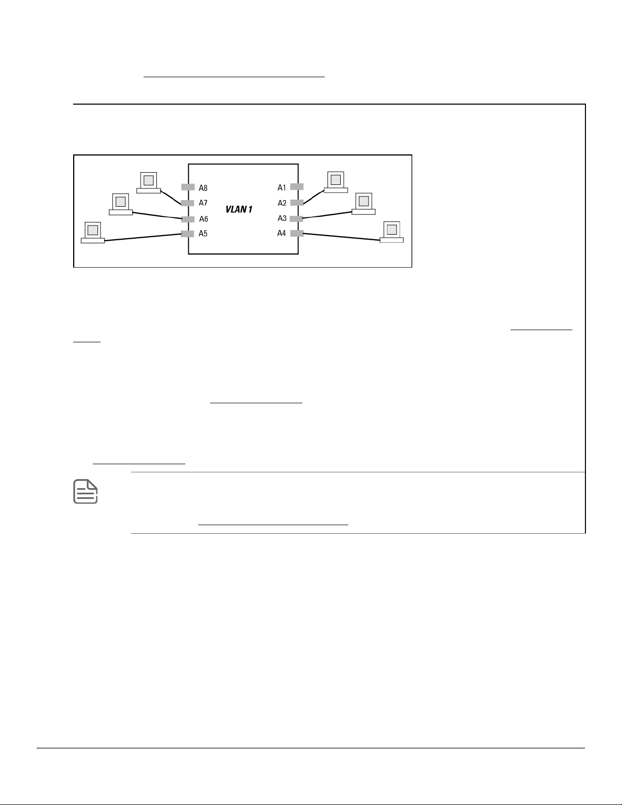
Default VLAN:
This port-based VLAN is always present in the switch and, in the default conguration, includes all ports as
members. See VLAN support and the default VLAN on page 53.
Except for an IP address and subnet, no conguration steps are needed.
A switch in the default VLAN conguration
In this example, devices connected to these ports are in the same broadcast domain.
Primary VLAN:
The switch uses this port-based VLAN to run certain features and management functions, including DHCP/
Bootp responses for switch management. In the default conguration, the Default VLAN is also the Primary
VLAN. However, any port-based, non-default VLAN can be designated the Primary VLAN. See The primary
VLAN on page 53.
Secure Management VLAN:
This optional, port-based VLAN establishes an isolated network for managing switches that support this
feature. Access to this VLAN and to the switch's management functions are available only through ports
congured as members. See The primary VLAN on page 53.
Voice VLANs:
This optional, port-based VLAN type enables separating, prioritizing, and authenticating voice trac moving
through your network, avoiding the possibility of broadcast storms aecting VoIP Voice-over-IP) operation.
See Using voice VLANs on page 52.
NOTE: In a multiple-VLAN environment that includes older switch models there may be
problems related to the same MAC address appearing on dierent ports and VLANs on the
same switch. In such cases, the solution is to impose cabling and VLAN restrictions. For more on
this topic, see Multiple VLAN considerations on page 27.
Multiple port-based VLANs
In the following example, routing within the switch is disabled (the default). Thus, communication between
any routable VLANs on the switch must go through the external router. In this case, VLANs W and X can
exchange trac through the external router, but trac in VLANs Y and Z is restricted to the respective
VLANs.
VLAN 1(the default) is present but not shown. The default VLAN cannot be deleted from the switch, but ports
assigned to other VLANs can be removed from the default VLAN. If internal (IP) routing is enabled on the
switch, then the external router is not needed for trac to move between port-based VLANs.
18 Aruba 2530 Advanced Trac Management Guide for
ArubaOS-Switch 16.09
Page 19
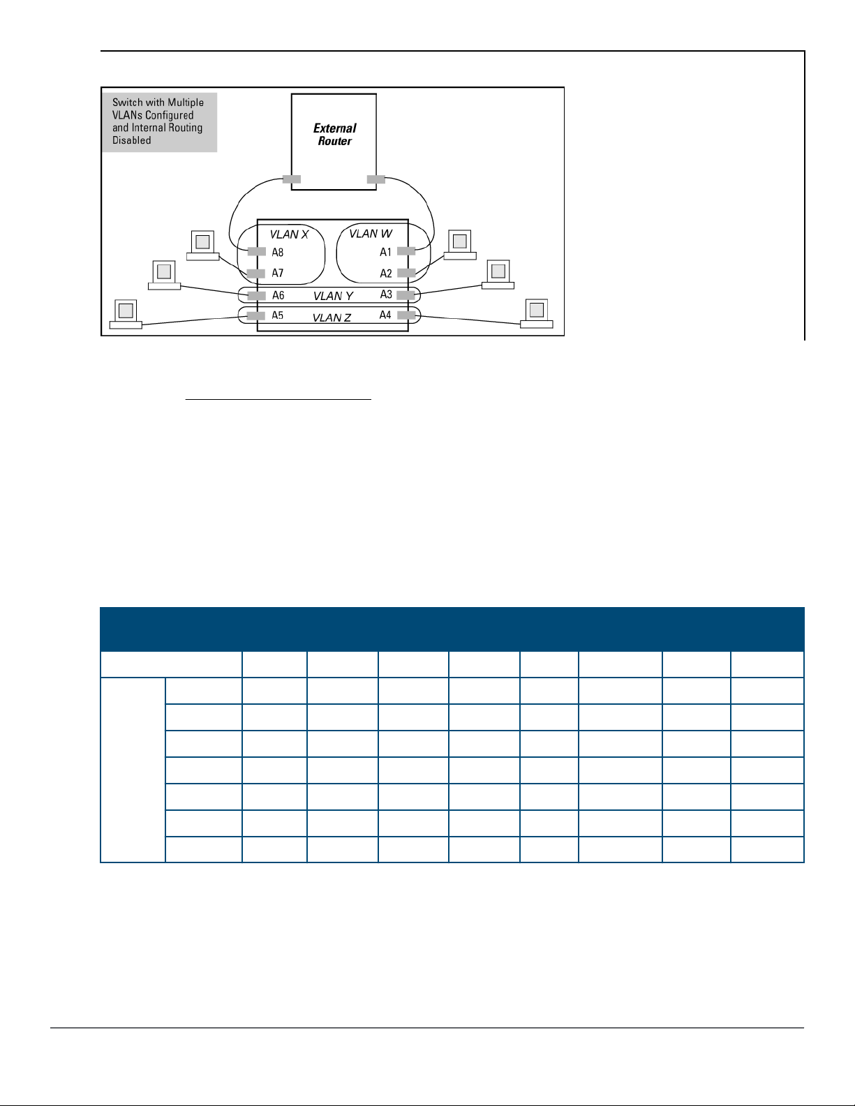
A switch with multiple VLANs congured and internal routing disabled
Protocol VLAN environment
The
gure in Multiple port-based VLANs illustrates a protocol VLAN environment also. In this case, VLANs
W and X represent routable protocol VLANs. VLANs Y and Z can be any protocol VLAN.
As noted for the discussion of multiple port-based VLANs, VLAN 1 is not shown. Enabling internal (IP) routing
on the switch allows IP trac to move between VLANs on the switch, but routable, non-IP trac always
requires an external router.
Routing options for VLANs
Table 2: Options for routing between VLAN types in the switch
Note that SNA and NETbeui are not routable protocol types. End stations intended to receive trac in these
protocols must be attached to the same physical network.
PortBased
Port-Based Yes — Yes — — — — —
Protocol IPX — Yes — — — — — —
IPX4 Yes — Yes — — — — —
IPV6 — — — Yes
ARP — — — — Yes
AppleTalk — — — — — Yes
SNA — — — — — — — —
NETbeui — — — — — — — —
IPX IPv4 IPv6 ARP AppleTalk SNA NETbeui
1
— — — —
1
— — —
1
— —
802.1Q VLAN tagging
A port can be a member of more than one VLAN of the same type if the device to which the port connects
complies with the 802.1Q VLAN standard.
For example, a port connected to a central server using a network interface card (NIC) that complies with the
802.1Q standard can be a member of multiple VLANs, allowing members of multiple VLANs to use the
server.
Chapter 2 VLANs 19
Page 20
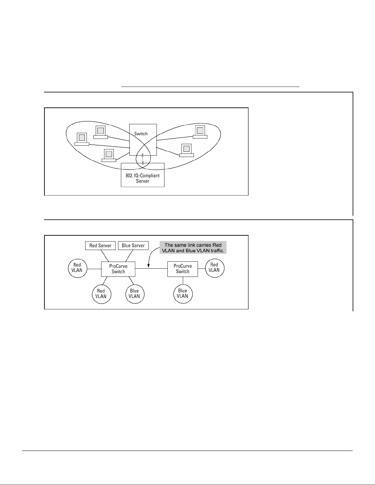
• Although these VLANs cannot communicate with each other through the server, they can all access the
server over the same connection from the switch.
• Where VLANs overlap in this way, VLAN "tags" are used in the individual packets to distinguish between
trac from dierent VLANs.
• A VLAN tag includes the particular VLAN ID. (VID) of the VLAN on which the packet was generated.
For more on this topic, see Conguring or changing static VLAN per-port settings (CLI) on page 34.
Overlapping VLANs using the same server
Similarly, using 802.1Q-compliant switches, you can connect multiple VLANs through a single switch-toswitch link.
Connecting multiple VLANs through the same link
Introducing tagged VLANs into legacy networks running only untagged VLANs
You can introduce 802.1Q-compliant devices into networks that have built untagged VLANs based on earlier
VLAN technology. The fundamental rule is that legacy/untagged VLANs require a separate link for each
VLAN, while 802.1Q, or tagged VLANs can combine several VLANs in one link. Thus on the 802.1Q-compliant
device, separate ports (congured as untagged) must be used to connect separate VLANs to non-802.1Q
devices.
20 Aruba 2530 Advanced Trac Management Guide for
ArubaOS-Switch 16.09
Page 21
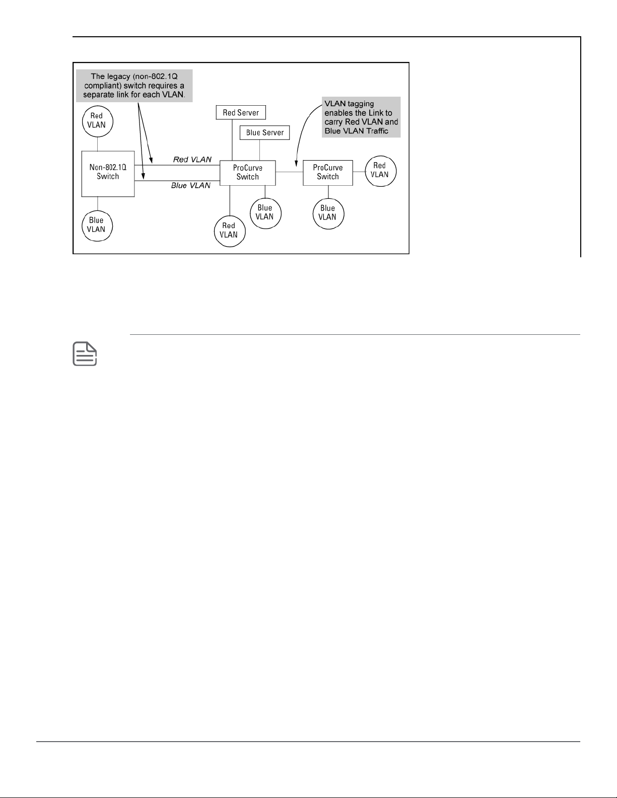
Tagged and untagged VLAN technology in the same network
VLAN tagging rules
When tagging is needed
When a port belongs to two or more VLANs of the same type, they remain as separate broadcast domains
and cannot receive trac from each other without routing.
NOTE:
If multiple, non-routable VLANs exist in the switch—such as NETbeui protocol VLANs—they
cannot receive trac from each other.
Inbound tagged packets
The switch requires VLAN tagging on a given port if the port will be receiving inbound, tagged VLAN trac
that should be forwarded.
If a tagged packet arrives on a port that is not a tagged member of the VLAN indicated by the packet's VID,
the switch drops the packet.
Similarly, the switch drops an inbound, tagged packet if the receiving port is an untagged member of the
VLAN indicated by the packet's VID.
Untagged packet forwarding
If the only authorized, inbound VLAN trac on a port arrives untagged, then the port must be an untagged
member of that VLAN. This is the case where the port is connected to a non-802.1Q compliant device or is
assigned to only one VLAN.
To enable an inbound port to forward an untagged packet, the port must be an untagged member of either
a protocol VLAN matching the packet's protocol, or an untagged member of a port-based VLAN.
That is, when a port receives an incoming, untagged packet, it processes the packet according to the
following ordered criteria:
Chapter 2 VLANs 21
Page 22
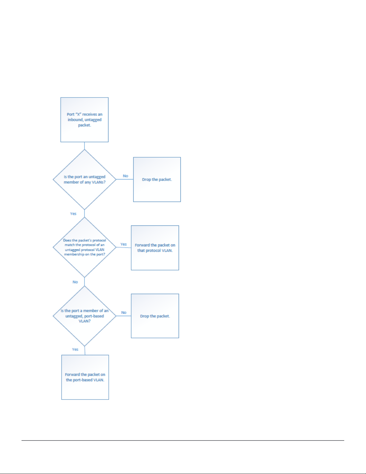
1. If the port has no untagged VLAN memberships, the switch drops the packet.
2. If the port has an untagged VLAN membership in a protocol VLAN that matches the protocol type of the
incoming packet, then the switch forwards the packet on that VLAN.
3. If the port is a member of an untagged, port-based VLAN, the switch forwards the packet to that VLAN.
Otherwise, the switch drops the packet.
Figure 1: Untagged VLAN operation
22 Aruba 2530 Advanced Trac Management Guide for
ArubaOS-Switch 16.09
Page 23
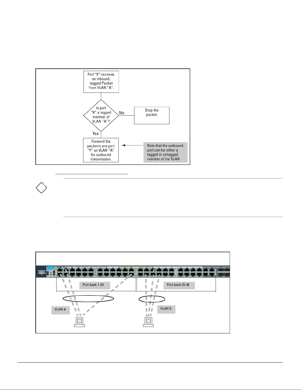
Tagged packet forwarding
If a port is a tagged member of the same VLAN as an inbound, tagged packet received on that port, then the
switch forwards the packet to an outbound port on that VLAN.
To enable the forwarding of tagged packets, any VLAN to which the port belongs as a tagged member must
have the same VID as that carried by the inbound, tagged packets generated on that VLAN.
Figure 2: Tagged VLAN operation
See also Multiple VLAN considerations on page 27.
CAUTION: Rate limiting may behave unpredictably on a VLAN if the VLAN spans multiple
modules or port-banks.
This also applies if a port on a dierent module or port-bank is added to an existing VLAN.
Hewlett Packard Enterprise does not recommend conguring rate limiting on VLANs that
include ports spanning modules or port-banks.
In the following example, ports 2, 3 and 24 form one VLAN, with ports 1 through 24 in the same port-bank.
Ports 28, 29 and 32 form a second VLAN. These ports are also in the same port-bank, which includes ports
25 through 48. Rate limiting will operate as expected for these VLANs.
Figure 3: Example of VLANs using ports from the same port-bank for each VLAN
Applying VLAN tagging
Chapter 2 VLANs 23
Page 24
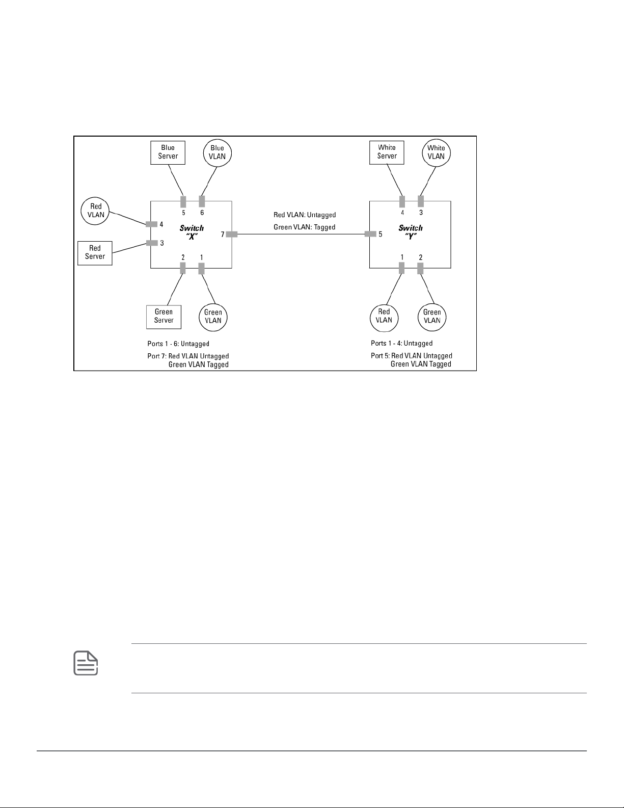
Example of tagged and untagged VLAN port assignments
If port 7 on an 802.1Q-compliant switch is assigned to only the Red VLAN, the assignment can remain
"untagged" because the port will forward trac only for the Red VLAN. However, if both the Red and Green
VLANs are assigned to port 7, then at least one of those VLAN assignments must be "tagged" so that Red
VLAN trac can be distinguished from Green VLAN trac.
Figure 4: Tagged and untagged VLAN port assignments
In switch X:
• VLANs assigned to ports X1 - X6 can be untagged because there is only one VLAN assignment per port.
Red VLAN trac will go out only the Red ports, Green VLAN trac will go out only the Green ports, and so
on. Devices connected to these ports do not have to be 802.1Q-compliant.
• However, because both the Red VLAN and the Green VLAN are assigned to port X7, at least one of the
VLANs must be tagged for this port.
In switch Y:
• VLANs assigned to ports Y1 - Y4 can be untagged because there is only one VLAN assignment per port.
Devices connected to these ports do not have to be 802.1Q-compliant.
• Because both the Red VLAN and the Green VLAN are assigned to port Y5, at least one of the VLANs must
be tagged for this port.
In both switches:
The ports on the link between the two switches must be congured the same. As shown in the following
gure, the Red VLAN must be untagged on port X7 and Y5 and the Green VLAN must be tagged on port X7
and Y5, or the opposite way.
NOTE: Each 802.1Q-compliant VLAN must have its own unique VID number and that VLAN must
be given the same VID in every device where congured. That is, if the Red VLAN has a VID of 10
in switch X, then 10 must also be the Red VID in switch Y.
Figure 5: Example of VLAN ID numbers assigned in the VLAN names screen
24 Aruba 2530 Advanced Trac Management Guide for
ArubaOS-Switch 16.09
Page 25
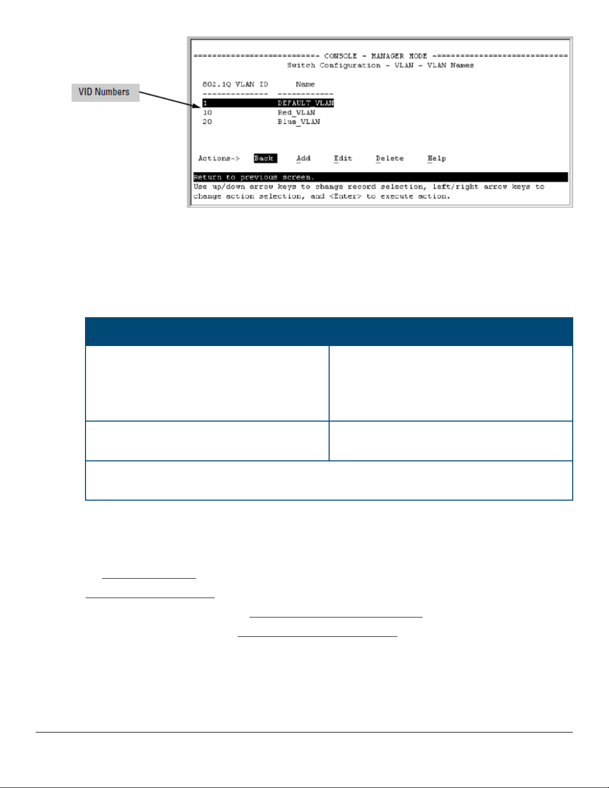
Additional VLAN tagging considerations
• Since the purpose of VLAN tagging is to allow multiple VLANs on the same port, any port that has only
one VLAN assigned to it can be
for that port arrives untagged.
• Any port with two or more VLANs of the same type can have one such VLAN assigned as "Untagged." All
other VLANs of the same type must be
Port-Based VLANs Protocol VLANs
congured as "Untagged" (the default) if the authorized inbound trac
congured as "Tagged," that is:
A port can be a member of one untagged, portbased VLAN. All other port-based VLAN
assignments for that port must be tagged.
A port can be a tagged member of any port-based
VLAN.
A given VLAN must have the same VID on all 802.1Q-compliant devices in which the VLAN occurs. Also,
the ports connecting two 802.1Q devices should have identical VLAN congurations.
• If all end nodes on a port comply with the 802.1Q standard and are congured to use the correct VID, you
can congure all VLAN assignments on a port as "Tagged" if doing so either makes it easier to manage
your VLAN assignments, or if the authorized, inbound trac for all VLANs on the port will be tagged.
For a summary and owcharts of untagged and tagged VLAN operation on inbound trac, see the following
under VLAN tagging rules on page 21:
• "Inbound Tagged Packets"
• "Untagged Packet Forwarding" and Figure 1: Untagged VLAN operation on page 22
• "Tagged Packet Forwarding" and Figure 2: Tagged VLAN operation on page 23
A port can be an untagged member of one
protocol-based VLAN of each protocol type. When
assigning a port to multiple, protocol-based VLANs
sharing the same type, the port can be an
untagged member of only one such VLAN.
A port can be a tagged member of any protocolbased VLAN. See above.
Chapter 2 VLANs 25
Page 26
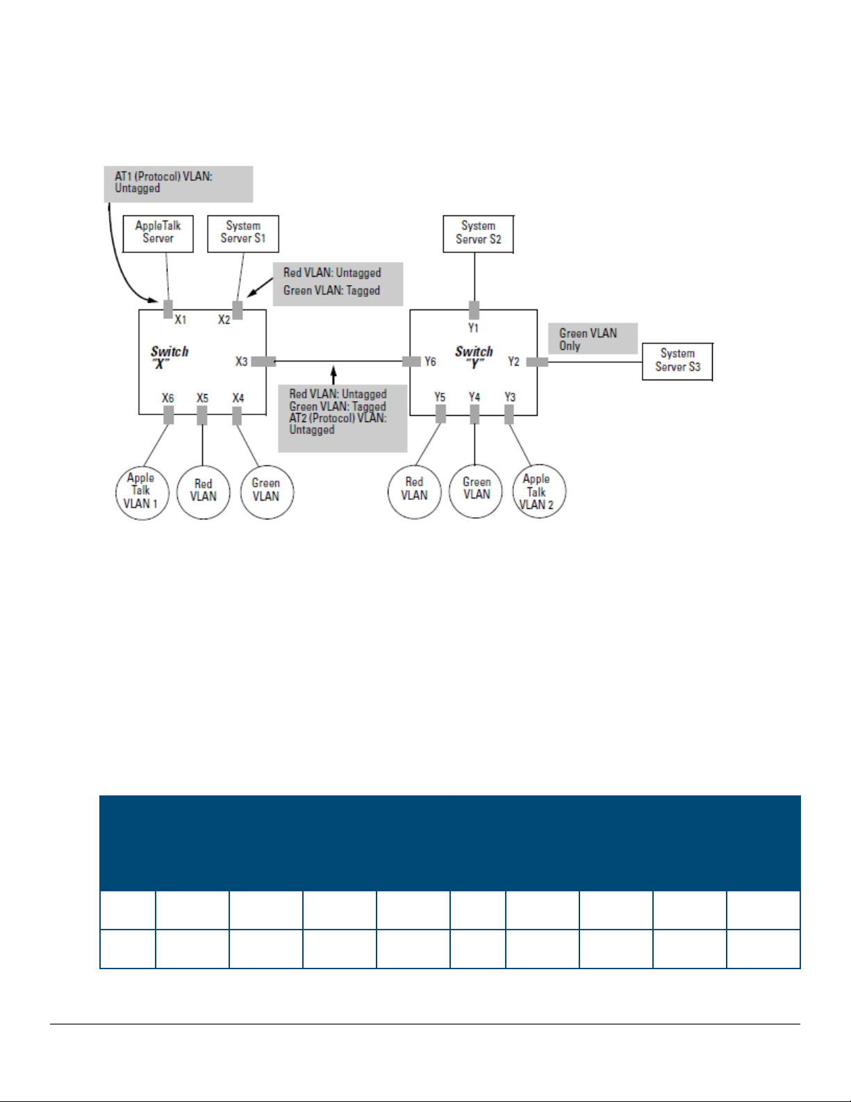
Example of Networked 802.1Q-compliant devices with multiple VLANs on some
ports
In the following network, switches X and Y and servers S1, S2, and the AppleTalk server are 802.1Qcompliant. (Server S3 could also be 802.1Q-compliant, but it makes no dierence for this example.) This
network includes both protocol-based (AppleTalk) VLANs and port-based VLANs.
• The VLANs assigned to ports X4 - X6 and Y2 - Y5 can all be untagged because there is only one VLAN
assigned per port.
• Port X1 has two AppleTalk VLANs assigned, which means that one VLAN assigned to this port can be
untagged and the other must be tagged.
• Ports X2 and Y1 have two port-based VLANs assigned, so one can be untagged and the other must be
tagged on both ports.
• Ports X3 and Y6 have two port-based VLANs and one protocol-based VLAN assigned. Thus, one portbased VLAN assigned to this port can be untagged and the other must be tagged. Also, since these two
ports share the same link, their VLAN congurations must match.
In the table, "No" means that the port is not a member of that VLAN. For example, port X3 is not a member
of the Red VLAN and does not carry Red VLAN trac. Also, if GVRP were enabled (port-based only), Auto
would appear instead of No.
Switch X Switch Y
Port AT-1
VLAN
X1 Untagged Tagged No No Y1 No No Untagged Tagged
AT-2
VLAN
Red
VLAN
Green
VLAN
Port AT-1
VLAN
AT-2
VLAN
Red
VLAN
Green
VLAN
X2 No No Untagged Tagged Y2 No No No Untagged
Table Continued
26 Aruba 2530 Advanced Trac Management Guide for
ArubaOS-Switch 16.09
Page 27

Switch X Switch Y
Port AT-1
VLAN
X3 No Untagged Untagged Tagged Y3 No Untagged No No
X4 No No No Untagged Y4 No No No Untagged
X5 No No Untagged No Y5 No No Untagged No
X6 Untagged No No No Y6 No Untagged Untagged Tagged
NOTE: VLAN congurations on ports connected by the same link must match. Because ports X2
and Y5 are opposite ends of the same point-to-point connection, both ports must have the
same VLAN conguration, conguring the Red VLAN as "Untagged" and the Green VLAN as
"Tagged.”
AT-2
VLAN
Red
VLAN
Green
VLAN
Port AT-1
VLAN
AT-2
VLAN
Red
VLAN
Green
VLAN
Multiple VLAN considerations
Switches use a forwarding database to maintain awareness of which external devices are located on which
VLANs. Some switches, such as the switches covered in this guide, have a multiple forwarding database,
which means the switch allows multiple database entries of the same MAC address, with each entry showing
the (dierent) source VLAN and source port. Other switch models have a single forwarding database, which
allows only one database entry of a unique MAC address, along with the source VLAN and source port on
which it is found. All VLANs on a switch use the same MAC address. Thus, connecting a multiple forwarding
database switch to a single forwarding database switch where multiple VLANs exist imposes some cabling
and port VLAN assignment restrictions. The following table illustrates the functional dierence between the
two database types.
Table 3: Forwarding database content
Multiple forwarding database Single forwarding database
MAC address Destination
VLAN ID
0004ea-84d9f4 1 A5 0004ea-84d9f4 100 A9
0004ea-84d9f4 22 A12 0060b0-880af9 105 A10
0004ea-84d9f4 44 A20 0060b0-880a81 107 A17
0060b0-880a81 33 A20
This database allows multiple destinations for the
same MAC address. If the switch detects a new
destination for an existing MAC entry, it just adds a
new instance of that MAC to the table.
All switches covered in this guide use a multiple forwarding database.
Destination
port
MAC address Destination
VLAN ID
This database allows only one destination for a MAC
address. If the switch detects a new destination for
an existing MAC entry, it replaces the existing MAC
instance with a new instance showing the new
destination.
Destination
port
Chapter 2 VLANs 27
Page 28

Single forwarding database operation
When a packet arrives with a destination MAC address that matches a MAC address in the switch's
forwarding table, the switch tries to send the packet to the port listed for that MAC address. But if the
destination port is in a dierent VLAN than the VLAN on which the packet was received, the switch drops the
packet. This is not a problem for a switch with a multiple forwarding database because the switch allows
multiple instances of a given MAC address, one for each valid destination. However, a switch with a single
forwarding database allows only one instance of a given MAC address.
TIP: If you connect both switch types through multiple ports or trunks belonging to dierent
VLANs and enable routing on the switch with the multiple-forwarding database, then the port
and VLAN record maintained on the switch with the single-forwarding database for the multipleforwarding database can change frequently. This may cause poor performance and the
appearance of an intermittent or broken connection.
Switch performance is unreliable
The following example provides a method to identify and correct an unsupported
conguration.
Symptom
Poor switch performance, unreliable switch performance, dropped packets, discarded packets, appearance
of intermittent or broken links.
Cause
Incorrect switch conguration.
As shown in the following gure, two switches are connected using two ports on each, and the MAC address
table for Switch A will sometimes record the switch as accessed on port A1 (VLAN 1) and at other times as
accessed on port B1 (VLAN 2).
Procedure
1. PC A sends an IP packet to PC B.
2. The packet enters VLAN 1 in the switch with the MAC address of the switch in the destination eld.
Because the switch has not yet learned this MAC address, it does not nd the address in its address table
and oods the packet out all ports, including the VLAN 1 link (port A1) to the switch. The switch then
routes the packet through the VLAN 2 link to the switch, which forwards the packet on to PC B. Because
the switch received the packet from the switch on VLAN 2 (port B1), the switch's single forwarding
database records the switch as being on port B1 (VLAN 2).
3. PC A now sends a second packet to PC B. The packet again enters VLAN 1 in the switch with the MAC
address of the switch in the destination eld. However, this time the switch's single forwarding database
indicates that the switch is on port B1 (VLAN 2) and the switch drops the packet instead of forwarding it.
4. Later, the switch transmits a packet to the switch through the VLAN 1 link and the switch updates its
address table to show that the switch is on port A1 (VLAN 1) instead of port B1 (VLAN 2). Thus, the
switch's information on the location of the switch changes over time, and the switch discards some
28 Aruba 2530 Advanced Trac Management Guide for
ArubaOS-Switch 16.09
Page 29
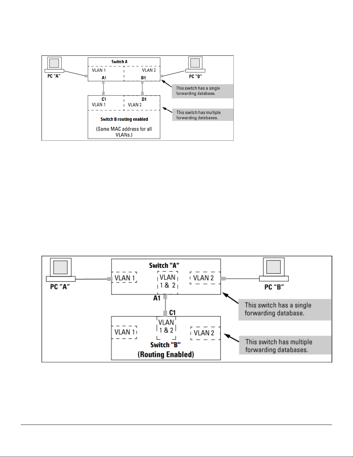
packets directed through it for the switch. This causes poor performance and the appearance of an
intermittent or broken link.
Figure 6: Invalid forwarding conguration
Action/solution
Recongure the switches in the conguration.
Procedure
1. Use only one cable or port trunk between single-forwarding and multiple-forwarding database devices.
2. Congure the link with multiple, tagged VLANs.
3. To increase network bandwidth of the connection between devices, use a trunk of multiple physical links.
Following these rules, the switch forwarding database always lists the switch MAC address on port A1 and
the switch will send trac to either VLAN on the switch.
Figure 7: Solution for single-forwarding to multiple-forwarding database devices in a multiple VLAN environment
Connecting the Switch to another switch with a multiple forwarding database (Example)
Use one or both of the following connection options:
Chapter 2 VLANs 29
Page 30
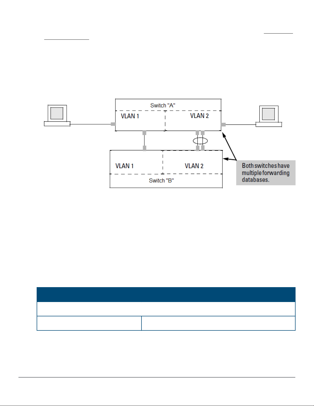
• A separate port or port trunk interface for each VLAN. This results in a forwarding database having
multiple instances of the same MAC address with dierent VLAN IDs and port numbers. See Forwarding
database content. The fact that the switches covered by this guide use the same MAC address on all
VLAN interfaces causes no problems.
• The same port or port trunk interface for multiple (tagged) VLANs. This results in a forwarding database
having multiple instances of the same MAC address with dierent VLAN IDs, but the same port number.
Allowing multiple entries of the same MAC address on dierent VLANs enables topologies such as the
following:
Figure 8: Topology for devices with multiple forwarding databases in a multiple VLAN environment
Conguring VLANs
The CLI congures and displays port-based and protocol-based VLANs.
In the factory default state, the switch is enabled for up to 256 VLANs, all ports belong to the default primary
VLAN and are in the same broadcast/multicast domain. You can recongure the switch to support more
VLANs . The maximum VLANs allowed varies according to the switch series.
The number of VLANs allowed on a switch
The factory default number of VLANs is 256.
You can
maximum VLANs allowed varies according to the switch series. The maximum VLAN values for the switch
documented in this guide are as follows:
Attribute MAX Number of VLANs
2530 Switch Series; YA/YB code, 2540 Switch Series; YC code
VLAN 512
recongure the switch to support more VLANs using the max-vlans command or the GUI. The
Table Continued
30 Aruba 2530 Advanced Trac Management Guide for
ArubaOS-Switch 16.09
Page 31

Attribute MAX Number of VLANs
IP VLAN 512 total with up to:
• 512 IPv4
• 512 IPv6
static routes 256 total
The maximum VIDs is 4094.
Per-port static VLAN conguration options example
This example shows the options available to assign individual ports to a static VLAN.
GVRP, if congured, aects these options and the VLAN behavior on the switch.
Figure 9: Comparing per-port VLAN options with and without GVRP
Table 4: Per-port VLAN conguration options
Parameter Eect on port participation in designated VLAN
Tagged
Untagged
Allows the port to join multiple VLANs.
• Allows VLAN connection to a device that is congured for an untagged VLAN
instead of a tagged VLAN.
• A port can be an untagged member of only one port-based VLAN.
• A port can be an untagged member of only one protocol-based VLAN for any
given protocol type.
For example, if the switch is congured with the default VLAN plus three protocolbased VLANs that include IPX, then port 1 can be an untagged member of the
default VLAN and one of the protocol-based VLANs.
Table Continued
Chapter 2 VLANs 31
Page 32

Parameter Eect on port participation in designated VLAN
No or Auto No: When the switch is not GVRP-enabled; prevents the port from joining that
VLAN.
Auto: When GVRP is enabled on the switch; it allows the port to dynamically join
any advertised VLAN that has the same VID.
Forbid
Prevents the port from joining the VLAN, even if GVRP is enabled on the switch.
Conguring port-based VLAN parameters
NOTE: The CLI congures and displays both port-based and protocol-based VLANs (see Using
the CLI to congure port-based and protocol-based VLAN parameters on page 32.
In the factory default state, the switch is enabled for up to 256 VLANs, all ports belong to the default primary
VLAN and are in the same broadcast/multicast domain. The default VLAN is also the default Primary VLAN;
see The primary VLAN on page 53. In addition to the default VLAN, you can congure additional static
VLANs by adding new VLAN names and VIDs, and then assigning one or more ports to each VLAN. (The
maximum of VLANs includes the default VLAN, all additional static VLANs you congure, and any dynamic
VLANs the switch creates if you enable GVRP; see GVRP on page 62.) Each port can be assigned to multiple
VLANs by using VLAN tagging; see VLAN tagging rules on page 21.)
Using the CLI to congure port-based and protocol-based VLAN
parameters
In the factory default state, all ports on the switch belong to the port-based default VLAN (DEFAULT_VLAN;
VID=1) and are in the same broadcast/multicast domain.
The default VLAN is also the Primary VLAN.
You can
to each VLAN.
congure additional static VLANs by adding new VLAN names and then assigning one or more ports
The maximum VLANs accepted by the switch varies according to the switch series. VIDs numbered up to
4094 are allowed. This must include the default VLAN and any dynamic VLANs the switch creates if you
enable GVRP (see GVRP on page 62).
NOTE: Each port can be assigned to multiple VLANs by using VLAN tagging. See VLAN tagging
rules on page 21.
Creating a new static VLAN (port-based or protocol-based) (CLI)
The vlan <vid> command operates in the global conguration context to congure a static VLAN and/or
take the CLI to a specied VLAN's context.
Syntax:
vlan <vid> | <ascii-name-string>
no vlan <vid>
If <vid> does not exist in the switch, this command creates a port-based VLAN with the specied <vid>
If the command does not include options, the CLI, moves to the newly created VLAN context.
32 Aruba 2530 Advanced Trac Management Guide for
ArubaOS-Switch 16.09
Page 33

If an optional name is not specied, the switch assigns a name in the default format VLAN n, where n is the
<vid> assigned to the VLAN.
If the VLAN exists and you enter either the <vid> or the <ascii-name-string> ,the CLI moves to the
specied VLAN's context.
The no form of the command deletes the VLAN as follows:
If one or more ports belong only to the VLAN to be deleted, the CLI noties you that these ports will be
moved to the default VLAN and prompts you to continue the deletion. For member ports that also belong to
another VLAN, there is no move prompt.
protocol [ipx | ipv4 | ipv6 | arp | appletalk | sna | netbeui]
Congures a static, protocol VLAN of the specied type.
If multiple protocols are congured in the VLAN, the no form removes the specied protocol
If a protocol VLAN is congured with only one protocol type and you use the no form of this command to
remove that protocol, the switch changes the protocol VLAN to a port-based VLAN (if the VLAN does not
have an untagged member port).
If an untagged member port exists on the protocol VLAN, you must either convert the port to a tagged
member or remove the port from the VLAN before removing the last protocol type from the VLAN.
NOTE: If you create an IPv4 protocol VLAN, you must assign the ARP protocol option to it to
provide IP address resolution. Otherwise, IP packets are not deliverable. A Caution message
appears in the CLI if you congure IPv4 in a protocol VLAN that does not already include the ARP
protocol option. The same message appears if you add or delete another protocol in the same
VLAN.
name <ascii-name-string>
When included in a vlan command to create a new static VLAN, this command species a non-default VLAN
name. Also used to change the current name of an existing VLAN.
NOTE: Avoid spaces and the following characters in the <ascii-name-string> entry: @, #:,
$, ^, &, *, ( and). To include a blank space in a VLAN name, enclose the name in single or
double quotes.
voice
Designates a VLAN for VoIP use. For more on this topic, see Using voice VLANs on page 52.
NOTE: You can use these options from the conguration level by beginning the command with
vlan <vid> , or from the context level of the specic VLAN by just entering the command
option.
Creating a new port-based static VLAN
The following example shows how to create a new port-based, static VLAN with a VID of 100 using the
following steps:
1. To create the new VLAN, type the vlan 100 command.
2. To show the VLANs currently congured in the switch, type the show vlans command.
Chapter 2 VLANs 33
Page 34

If the Management VLAN eld (Primary VLAN : DEFAULT_VLAN Management VLAN shown in the display
information below) is empty, a Secure Management VLAN is not congured in the switch. For more
information on conguring a secure management VLAN, see The secure Management VLAN on page 54.
switch(config)# vlan 100
switch(config)# show vlans
Status and Counters - VLAN Information
Maximum VLANs to support : 16
Primary VLAN : DEFAULT_VLAN
Management VLAN :
VLAN ID Name Status Voice Jumbo
------- -------------------- ------------ ----- ---- 1 DEFAULT_VLAN Port-based No No
100 VLAN100 Port-based No No
Changing the VLAN context level
To go to a dierent VLAN context level, such as to the default VLAN:
switch(vlan-100)# vlan default_vlan
switch(vlan-1)# _
Conguring or changing static VLAN per-port settings (CLI)
Syntax:
vlan <vid>
no vlan <vid>
This command, used with the options listed below, changes the name of an existing static VLAN and the perport VLAN membership settings.
NOTE: You can use these options from the conguration level by beginning the command with
vlan <vid>, or from the context level of the specic VLAN by just entering the command
option.
tagged <port-list>
Congures the indicated port as Tagged for the specied VLAN. The no version sets the port to either No or
(if GVRP is enabled) to Auto.
untagged <port-list>
Congures the indicated port as Untagged for the specied VLAN. The no version sets the port to either No
or (if GVRP is enabled) to Auto.
forbid <port-list>
34 Aruba 2530 Advanced Trac Management Guide for
ArubaOS-Switch 16.09
Page 35

Used in port-based VLANs, congures <port-list> as forbidden to become a member of the specied
VLAN, as well as other actions. Does not operate with option not allowed protocol VLANs. The no version
sets the port to either No or (if GVRP is enabled) to Auto. See GVRP on page 62.
auto <port-list>
Available if GVRP is enabled on the switch. Returns the per-port settings for the specied VLAN to Auto
operation. Auto is the default per-port setting for a static VLAN if GVRP is running on the switch. For
information on dynamic VLAN and GVRP operation, see GVRP on page 62.
Changing the VLAN name and set ports to tagged
Suppose that there is a VLAN named VLAN100 with a VID of 100 and all ports are set to No for this VLAN. To
change the VLAN name to Blue_Team and set ports A1 - A5 to Tagged, use the following commands:
switch(config)# vlan 100 name Blue_Team
switch(config)# vlan 100 tagged a1-a5
Moving the context level
To move to the vlan 100 context level and execute the same commands:
switch(config)# vlan 100
switch(vlan-100)# name Blue_Team
switch(vlan-100)# tagged a1-a5
Changing tagged ports
Similarly, to change the tagged ports in the above examples to No (or Auto, if GVRP is enabled), use either of
the following commands.
At the global cong level, use:
switch(config)# no vlan 100 tagged a1-a5
or
At the VLAN 100 context level, use:
switch(vlan-100)# no tagged a1-a5
NOTE: You cannot use these commands with dynamic VLANs. Attempting to do so displays the
message VLAN already exists with no change.
Converting a dynamic VLAN to a static VLAN (CLI)
Syntax:
static-vlan <vlan-id>
Converts a dynamic, port-based VLAN membership to static, port-based VLAN membership (allows portbased VLANs only).
Chapter 2 VLANs 35
Page 36

For this command,<vlan-id> refers to the VID of the dynamic VLAN membership. Use show vlan to help
identify the VID.
This command requires that GVRP is running on the switch and a port is currently a dynamic member of the
selected VLAN.
After you convert a dynamic VLAN to static, you must congure the switch's per-port participation in the
VLAN in the same way that you would for any static VLAN. For GVRP and dynamic VLAN operation, see GVRP
on page 62.
Converting a dynamic VLAN to a port-based static VLAN
Suppose a dynamic VLAN with a VID of 125 exists on the switch. The following command converts the VLAN
to a port-based, static VLAN:
switch(config)# static-vlan 125
Deleting a static VLAN (CLI)
Syntax:
vlan <vid>
no vlan <vid>
CAUTION: Before deleting a static VLAN, reassign all ports in the VLAN to another VLAN.
Deleting a static VLAN
If ports B1-B5 belong to both VLAN 2 and VLAN 3 and ports B6-B10 belong to VLAN 3, deleting VLAN 3
causes the CLI to prompt you to approve moving ports B6 - B10 to VLAN 1 (the default VLAN). (Ports B1-B5
are not moved because they still belong to another VLAN.)
switch(config)# no vlan 3
The following ports will be moved to the default VLAN:
B6-B10
Do you want to continue?
[y/n] Y
switch(config)#
Deleting multiple VLANs
The interface command enables you to add or delete interfaces from multiple tagged or untagged VLANs
or SVLANs using a single command. Interfaces can be added or deleted for up to 256 VLANs at a time. If
more than 256 VLANs are specied, an error is displayed. The forbid option prevents an interface from
becoming a member of the specied VLANs or SVLANs when used with GVRP.
36 Aruba 2530 Advanced Trac Management Guide for
ArubaOS-Switch 16.09
Page 37

Syntax
interface <port-list> <tagged | untagged | forbid> <vlan | svlan <vlan-id-list>>
no interface <port-list> <tagged | untagged | forbid> <vlan | svlan <vlan-id-list>>
The specied interfaces are added to existing VLANs or SVLANs. If a VLAN or SVLAN does not exist, an error
message displays.
The no form of the command removes the specied interfaces from the specied VLANs or SVLANs.
The forbid option prevents an interface from becoming a member of the specied VLANs or SVLANs. It is
executed in interface context.
Removing an interface from several VLANs
The vlan-id-list includes a comma-separated list of VLAN IDs and/or VLAN ID ranges.
To remove interface 1 from VLANs 1, 3, 5, 6, 7, 8, 9, 10
switch(config)# no interface 1,6,7-10 tagged vlan 1,3,5-10
To specify that an interface cannot become a member of VLANs 4 and 5
switch(config)# interface 2 forbid vlan 4-5
Using IP enable/disable for all VLANs
You can administratively disable the IP address on specied VLANs with static IP addresses without
removing the Layer 3 conguration. The switch can be pre-congured as a backup router, then quickly
transition from backup to active by re-enabling Layer 3 routing on one or more VLANs. While the switch is in
“backup” mode, it will still be performing Layer 2 switching.
A MIB object will be toggled to make Layer 3 routing active or inactive on a VLAN.
Interaction with other features
This feature aects management access to the switch as follows:
• IP—SNMP, Telnet, SSH, HTTP, TFTP, SCP, SFTP
• Routing—RIP, OSPF, PIM, VRRP
When the disable layer3 command is congured on a VLAN, the behavior is as if no IP address were
congured for that VLAN. There is no other change in behavior.
Syntax:
disable layer3 vlan <vid> <vid range>
no disable layer3 vlan <vid> <vid range>
In cong context, turns o Layer 3 routing for the specied VLAN or VLANs. When executed in vlan context,
turns o Layer 3 routing for that VLAN.
The no form turns on Layer 3 routing for the specied VLAN or VLANs.
Chapter 2 VLANs 37
Page 38

The show ip command displays disabled in the IP Cong column if Layer 3 has been disabled, or if the
VLAN has no IP conguration. You can tell which is the case by viewing the remaining columns; if there is no
IP conguration, the remaining columns are blank.
Displaying a VLAN disabled for Layer 3
switch(config)# show ip
Internet (IP) Service
IP Routing : Disabled
Default Gateway : 172.22.16.1
Default TTL : 64
Arp Age : 20
Domain Suffix :
DNS server :
Proxy ARP
VLAN | IP Config IP Address Subnet Mask Std Local
----------------- + ---------- --------------- --------------- ---- ---- DEFAULT_VLAN | DHCP/Bootp 172.22.18.100 255.255.248.0 No No
VLAN3 | Disabled 172.17.17.17 255.255.255.0 No No
VLAN6 | Disabled
VLAN7 | Manual 10.7.7.1 255.255.255.0 No No
For IPv6, the Layer 3 Status
Displaying IPv6 Layer 3 status for a VLAN
switch(config)# show ipv6
Internet (IPv6) Service
IPv6 Routing : Disabled
Default Gateway :
ND DAD : Enabled
DAD Attempts : 3
Vlan Name : DEFAULT_VLAN
IPv6 Status : Disabled
Layer 3 Status : Enabled
Vlan Name : layer3_off_vlan
IPv6 Status : Disabled
Layer 3 Status : Disabled
Address | Address
Origin | IPv6 Address/Prefix Length Status
---------- + ------------------------------------------- ---------- manual | abcd::1234/32 tentative
autoconfig | fe80::218:71ff:febd:ee00/64 tentative
eld displays the status of Layer 3 on that VLAN.
Interactions with DHCP
Disabling Layer 3 functionality and DHCP are mutually exclusive, with DHCP taking precedence over disable
layer3 on a VLAN. The following interactions occur:
38 Aruba 2530 Advanced Trac Management Guide for
ArubaOS-Switch 16.09
Page 39

• If the disable layer3 command is executed when DHCP is already congured, no disabling of the
VLAN occurs. This error message displays: “Layer 3 cannot be disabled on a VLAN that has DHCP
enabled.”
• From the CLI: If disable layer3 is congured already and an attempt is made to congure DHCP,
DHCP takes precedence and will be set. The warning message displays: “Layer 3 has also been enabled
on this VLAN since it is required for DHCP.”
• From the CLI: When disabling a range of VLAN IDs, this warning message displays: “Layer 3 will not be
disabled for any LANs that have DHCP enabled.”
• From SNMP: If the disable layer3 command is executed when DHCP is already congured, no
disabling of the VLAN occurs. An INCONSISTENT_VALUE error is returned.
• From SNMP: If disable layer3 is congured already and an attempt is made to congure DHCP, DHCP
takes precedence and will be set.
Changing the Primary VLAN (CLI)
For more information on Primary VLANs, see The primary VLAN on page 53.
To change the Primary VLAN (CLI), use the following command:
primary-vlan vid <ascii-name-string>
In the default VLAN conguration, the port-based default VLAN (DEFAULT_VLAN) is the Primary VLAN. This
command reassigns the Primary VLAN function to an existing, port-based, static VLAN. The switch cannot
reassign the Primary VLAN function to a protocol VLAN.
If you reassign the Primary VLAN to a non-default VLAN, to delete the Primary VLAN from the switch, you
must assign the Primary VLAN to another port-based static VLAN.
To identify the current Primary VLAN and list the available VLANs and their respective VIDs, use show
vlans.
Reassigning, renaming and displaying the VLAN command sequence
The following example shows how to reassign the Primary VLAN to VLAN 22 (rst command line), rename
the VLAN 22-Primary (second command line) and then display the result (third command line):
switch(config)# primary-vlan 22
switch(config)# vlan 22 name 22-Primary
switch(config)# show vlans
Status and Counters - VLAN Information
Maximum VLANs to support : 8
Primary VLAN : 22-Primary
Management VLAN :
VLAN ID Name Status Voice Jumbo
------- -------------------- ------------ ----- -----
1 DEFAULT_VLAN Static No No
22 22-Primary Static No No
Chapter 2 VLANs 39
Page 40

Conguring a secure Management VLAN (CLI)
Preparation
Procedure
1. Determine a VID and VLAN name suitable for your Management VLAN.
2. Plan your topology to use switches that support Management VLANs. See The secure Management
VLAN on page 54.
3. Include only the following ports:
a. Ports to which you will connect authorized management stations, such as Port A7 in the "Management
VLAN control in a LAN" example in The secure Management VLAN.
b. Ports on one switch that you will use to extend the Management VLAN to ports on other switches,
such as ports A1 in the "Management VLAN control in a LAN" example in The secure Management
VLAN.
4. Half-duplex repeaters dedicated to connecting management stations to the Management VLAN can also
be included in this topology. Any device connected to a half-duplex repeater in the Management VLAN
will also have Management VLAN access.
Congure the Management VLAN on the selected switch ports.
5.
6. Test the Management VLAN from all of the management stations authorized to use it, including any
SNMP-based network management stations. Also test any Management VLAN links between switches.
NOTE: If you congure a Management VLAN on a switch using a Telnet connection through a
port not in the Management VLAN, you will lose management contact with the switch if you log
o your Telnet connection or execute write memory and reboot the switch.
Conguring an existing VLAN as the Management VLAN (CLI)
Syntax:
management-vlan <vlan-id> | <vlan-name>
no management-vlan <vlan-id> | <vlan-name>
Congures an existing VLAN as the Management VLAN.
The no form disables the Management VLAN and returns the switch to its default management operation.
Default: Disabled. In this case, the VLAN returns to standard VLAN operation.
Switch conguration
You have congured a VLAN named My_VLAN with a VID of 100 and want to congure the switch to do the
following:
• Use My_VLAN as a Management VLAN (tagged, in this case) to connect port A1 on switch "A" to a
management station. The management station includes a network interface card with 802.1Q tagged
VLAN capability.
• Use port A2 to extend the Management VLAN to port B1 which is already congured as a tagged member
of My_VLAN, on an adjacent switch that supports the Management VLAN feature.
40 Aruba 2530 Advanced Trac Management Guide for
ArubaOS-Switch 16.09
Page 41

switch(config)# management-vlan 100
switch(config)# vlan 100 tagged a1
switch(config)# vlan 100 tagged a2
Conguration Example
Obtaining an IP address using DHCP (CLI)
Use DHCP to obtain an IPv4 address for your Management VLAN or a client on that VLAN. The following
examples illustrate when an IP address will be received from the DHCP server.
DHCP server on a Management VLAN
If Blue_VLAN is congured as the Management VLAN and the DHCP server is also on Blue_VLAN, Blue_VLAN
receives an IP address. Because DHCP Relay does not forward onto or o the Management VLAN, devices on
Red_VLAN cannot get an IP address from the DHCP server on Blue_VLAN (Management VLAN) and
Red_VLAN does not receive an IP address.
DHCP server on a dierent VLAN from the Management VLAN
If Red_VLAN is congured as the Management VLAN and the DHCP server is on Blue_VLAN, Blue_VLAN
receives an IP address but Red_VLAN does not.
Chapter 2 VLANs 41
Page 42

No Management VLANs congured
If no Management VLAN is congured, both Blue_VLAN and Red_VLAN receive IP addresses.
A client on a dierent Management VLAN from the DHCP server
If Red_VLAN is congured as the Management VLAN and the client is on Red_VLAN, but the DHCP server is
on Blue_VLAN, the client will not receive an IP address.
42 Aruba 2530 Advanced Trac Management Guide for
ArubaOS-Switch 16.09
Page 43

A DHCP server and client on the Management VLAN
If Blue_VLAN is congured as the Management VLAN, the client is on Blue_VLAN and the DHCP server is on
Blue_VLAN, the client receives an IP address.
Obtaining the IP address for a host that is on a dierent VLAN than the DHCP server
In the following example, the host is on VLAN 20 and is connected on port number 2 of the switch. The
DHCP server, however, is in VLAN 10 and is connected on port 10 of the switch.
Obtaining the IP address for a host that is on a dierent VLAN than the DHCP server
switch(config)# vlan 10
name "VLAN 10"
untagged 10
ip address 10.1.1.2 255.255.255.0
exit
vlan 20
name "VLAN 20"
untagged 2
ip address 100.99.1.1 255.255.255.0
ip helper-address 10.1.1.1
exit
Disabling the Management feature (CLI)
You can disable the Secure Management feature without deleting the VLAN.
Disabling the secure management feature
The following commands disable the Secure Management feature in the above example:
switch(config)# no management-vlan 100
switch(config)# no management-vlan my_vlan
For more information, see
The secure Management VLAN on page 54.
Chapter 2 VLANs 43
Page 44

Changing the number of VLANs allowed on the switch (CLI)
Syntax:
max-vlans<max number of vlans>
Use this command to specify the maximum number of VLANs allowed on the switch. The minimum value is
16. The maximum value varies according to the switch series.
For the 2530 switch series you can enter a max-vlans value of between 16–512.
The total number of allowed IP VLANs (IPv6 + IPv4) is 512.
If GVRP is enabled, this setting includes any dynamic VLANs on the switch. As part of implementing a new
setting, you must execute a write memory command to save the new value to the
then reboot the switch.
NOTE: If multiple VLANs exist on the switch, you cannot reset the maximum number of VLANs
to a value smaller than the current number of VLANs.
The following example shows the command sequence for changing the number of VLANs allowed to 20. You
can execute the commands to write memory and boot at another time.
Example of changing the number of allowed VLANs
switch(config)# max-vlans 20
This command will take effect after saving the configuration
and rebooting the system.
switch(config)# write memory
switch(config)# boot
This will reboot the system from the primary image, do you want to continue [y/n]? Y
startup-cong le and
Error Messages
An error message will be displayed, if you set the max-vlans value to a number that exceeds the allowable
value for the switch series.
If you set the max-vlans and later try to downgrade to an earlier version of the switch software that does
not allow that number of max-vlans, successful downgrade may be prevented.
Displaying a switch VLAN conguration
The show vlans command lists the VLANs currently running in the switch, with VID, VLAN name, and VLAN
status. Dynamic VLANs appear only if the switch is running with GVRP enabled and one or more ports has
dynamically joined an advertised VLAN. In the default conguration, GVRP is disabled.
Syntax:
show vlans
The following describes the elds displayed with this command (see the example output):
Maximum VLANs to support
Shows the number of VLANs the switch is currently congured to support.
Primary VLAN
See The primary VLAN on page 53.
Management VLAN
See The secure Management VLAN on page 54.
44 Aruba 2530 Advanced Trac Management Guide for
ArubaOS-Switch 16.09
Page 45

802.1Q VLAN ID
The VLAN identication number, or VID.
Name
The default or specied name assigned to the VLAN. For a static VLAN, the default name consists of
VLAN-x where x matches the VID assigned to that VLAN. For a dynamic VLAN, the name consists of
GVRP_x where x matches the applicable VID.
Status
Port-Based
Port-Based, static VLAN
Protocol
Protocol-Based, static VLAN
Dynamic
Port-Based, temporary VLAN learned through GVRP
Voice
Indicates whether a port-based VLAN is congured as a voice VLAN. See Using voice VLANs on page
52.
Jumbo
Indicates whether a VLAN is congured for Jumbo packets. For more on jumbos, see "Port Trac
Controls" in the management and conguration guide for your switch.
This example shows the listing from the show vlans command. When GVRP is disabled (the default),
Dynamic VLANs do not exist on the switch and do not appear in this listing. For more information, see GVRP
on page 62.
Displaying VLAN listing with GVRP enabled
switch# show vlans
Status and Counters - VLAN Information
Maximum VLANs to support : 256
Primary VLAN : DEFAULT_VLAN
Management VLAN :
VLAN ID Name | Status Voice Jumbo
------- -------------------- + ---------- ----- -----
1 DEFAULT_VLAN | Port-based No No
10 VLAN_10 | Port-based Yes Yes
15 VLAN_15 | Port-based No No
20 VLAN_20 | Protocol No No
33 VLAN_33 | Dynamic No No
Viewing the VLAN membership of one or more ports (CLI)
Syntax:
show vlan ports <port-list> [detail]
Displays VLAN information for an individual port or a group of ports, either cumulatively or on a detailed
per-port basis.
Chapter 2 VLANs 45
Page 46

port-list
Species a single port number or a range of ports (for example, a1-a16), or all for which to display
information.
detail
Displays detailed VLAN membership information on a per-port basis.
The following describes the elds displayed by the command (see example output):
Port name
The user-specied port name, if one has been assigned.
VLAN ID
The VLAN identication number, or VID.
Name
The default or specied name assigned to the VLAN. For a static VLAN, the default name consists of
VLAN-x where x matches the VID assigned to that VLAN. For a dynamic VLAN, the name consists of
GVRP_x where x matches the applicable VID.
Status
Port-Based
Port-Based, static VLAN.
Protocol
Protocol-Based, static VLAN.
Dynamic
Port-Based, temporary VLAN learned through GVRP.
Voice
Indicates whether a port-based VLAN is congured as a voice VLAN.
Jumbo
Indicates whether a VLAN is congured for jumbo packets. For more on jumbos, see "Port Trac
Controls" in the management and conguration guide for your switch.
Mode
Indicates whether a VLAN is tagged or untagged.
Displaying VLAN ports (cumulative listing)
switch(config)#show vlan ports a1-a24
Status and Counters - VLAN Information - for ports A1-A24
VLAN ID Name | Status Voice Jumbo
------- -------------------- + ---------- ----- -----
1 DEFAULT_VLAN | Port-based No No
10 VLAN_10 | Port-based Yes No
15 VLAN_15 | Protocol No No
Displaying VLAN ports (detailed listing)
switch(config)#show vlan ports a1-a3 detail
46 Aruba 2530 Advanced Trac Management Guide for
ArubaOS-Switch 16.09
Page 47

Status and Counters - VLAN Information - for ports A1
VLAN ID Name | Status Voice Jumbo Mode
------- -------------------- + ---------- ----- ----- --------
1 DEFAULT_VLAN | Port-based No No Untagged
10 VLAN_10 | Port-based Yes No Tagged
Status and Counters - VLAN Information - for ports A2
VLAN ID Name | Status Voice Jumbo Mode
------- -------------------- + ---------- ----- ----- --------
1 DEFAULT_VLAN | Port-based No No Untagged
20 VLAN_20 | Protocol No No Untagged
Status and Counters - VLAN Information - for ports A3
VLAN ID Name | Status Voice Jumbo Mode
------- -------------------- + ---------- ----- ----- --------
1 DEFAULT_VLAN | Port-based No No Untagged
33 VLAN_33 | Port-based No No Tagged
Viewing the conguration for a particular VLAN (CLI)
Syntax:
show vlans <vlan-id>
Uses the VID to identify and display the data for a
The following describes the elds displayed with this command (see example output):
802.1Q VLAN ID
The VLAN identication number, or VID.
Name
The default or specied name assigned to the VLAN. For a static VLAN, the default name consists of
VLAN-x where x matches the VID assigned to that VLAN. For a dynamic VLAN, the name consists of
GVRP_x where x matches the applicable VID.
Status
Port-Based
Port-Based, static VLAN.
Protocol
Protocol-Based, static VLAN
Dynamic
Port-Based, temporary VLAN learned through GVRP. See GVRP on page 62.
Voice
Indicates whether a port-based VLAN is congured as a voice VLAN. See Using voice VLANs on page
52.
specic static or dynamic VLAN.
Jumbo
Indicates whether a VLAN is congured for Jumbo packets. For more on jumbos, see "Port Trac
Controls" in the management and conguration guide for your switch.
Chapter 2 VLANs 47
Page 48

Port Information
Lists the ports congured as members of the VLAN.
DEFAULT
Shows whether a port is a tagged or untagged member of the listed VLAN.
Unknown VLAN
Shows whether the port can become a dynamic member of an unknown VLAN for which it receives an
advertisement. GVRP must be enabled to allow dynamic joining to occur.
Status
Shows whether the port is participating in an active link.
Displaying information for a specic static VLAN
switch(config)#show vlans 22
Status and Counters - VLAN Information - VLAN 22
VLAN ID : 22
Name : VLAN22
Status : Port-based
Voice : Yes
Jumbo : No
Port Information Mode Unknown VLAN Status
---------------- -------- ------------ ----------
12 Untagged Learn Up
13 Untagged Learn Up
14 Untagged Learn Up
15 Untagged Learn Down
16 Untagged Learn Up
17 Untagged Learn Up
18 Untagged Learn Up
Displaying information for a specic dynamic VLAN
The following example shows the information displayed for a specic dynamic VLAN. The show vlans
command lists this data when GVRP is enabled and at least one port on the switch has dynamically joined
the designated VLAN.
switch(config)# show vlans 22
Status and Counters - VLAN Information - VLAN 22
VLAN ID : 33
Name : GVRP_33
Status : Dynamic
Voice : No
Jumbo : No
Port Information Mode Unknown VLAN Status
---------------- -------- ------------ ----------
6 Auto Learn Up
48 Aruba 2530 Advanced Trac Management Guide for
ArubaOS-Switch 16.09
Page 49

Customizing the show VLANs output (CLI)
Syntax
show vlans custom [port <port-list>] <column-list>
Species the order you want information to display for the show vlans command. Displays information for
one port or a range of ports. If <port-list> is not specied, all ports display.
Fields that can be included in the customized display:
Field Display Example Default
width
id VLAN id 5 6
name VLAN name Vlan55 32
status Status Port-based 10
voice Voice enabled No 5
jumbo Jumbos
enabled
ipcong How the IP
address was
congured
ipaddr (IPv4)
ipaddr (IPv6)
ipmask The subnet
proxyarp Whether
localproxyarp Whether local
The IP
addresses
masks
proxy ARP is
congured
proxy ARP is
congured
No 5
Manual
Disabled
DHCP/BootP
10.10.10.3
fe80::212:79:fe8d:8000
255.255.255.6/64 (prex for
IPv6 is in format "/XX")
No 5
No 9
10
15 for IPv4
46 for IPv6
15
state "Up" if at
least one port
is up
Chapter 2 VLANs 49
Up 5
Page 50

Customizing the VLAN display
The following example displays id at its default width and name:20 allows up to 20 characters of the VLAN
name to be displayed. The columns selected for display are separated by spaces.
If the width of the column requested is smaller than the header name of the column, the display of the
header name is truncated.
switch(config)# show vlan custom A1-A3 id name:20 ipaddr state
Status and Counters - VLAN Information - Custom view
VLANID VLAN name IP Addr State
------ -------------------- --------------------------------- -----
1 DEFAULT_VLAN 15.255.134.74 Up
33 Vlan33 10.10.10.01 Up
44 Vlan44 15.255.164.13 Up
55 Vlan55 15.255.178.2 Down
15.255.178.3
15.255.178.4
60 Vlan60 fe80::212:79ff:fe8d:8000%vlan60 Up
Wrapping column headers
The total output wraps if it is longer than the terminal width; it is not truncated.
switch(config)# show vlan custom id
Status and Counters - VLAN Information - Custom view
VLANID
------
1
33
44
switch(config)# show vlan custom id:2
Status and Counters - VLAN Information - Custom view
VL
--
1
33
44
Using pattern matching with the show VLANs custom command
If a pattern matching command is in a search for a eld in the output of the show vlan custom command
and it produces an error, the error message may not be visible. For example, if you enter a command with
the pattern matching include option that contains an error (such as 'vlan' is misspelled) as in the following
example, the output may be empty:
switch(config)# show vlans custom 1-3 name vlun include vlan1
Hewlett Packard Enterprise recommends that you try the show vlans custom command rst to ensure
that there is output and then enter the command again with the pattern matching option.
50 Aruba 2530 Advanced Trac Management Guide for
ArubaOS-Switch 16.09
Page 51

Creating an alias for show VLAN commands (CLI)
Create an alias for a frequently used show vlans custom command to avoid entering the selected
columns each time you use the command.
Using a VLAN alias
switch(config)# alias showvlanstatus = “show vlan custom A1-A3 id name:20 status”
switch(config)# show vlan status
Status and Counters - VLAN Information - Custom view
VLANID VLAN name Status
------ -------------------- ----------
1 DEFAULT_VLAN Port-based
33 Vlan33 Port-based
Conguring a VLAN MAC address with heartbeat
interval
When installing routing switches in the place of existing routers in a network
Layer 3 VLAN migration by using the ip-recv-mac-address command at the VLAN conguration level to:
• Congure the MAC address of the previously installed router on each VLAN interface of a routing switch.
• Optionally congure the time interval to use for sending heartbeat packets with the congured MAC
address.
Syntax
ip-recv-mac-address <mac-address> interval <seconds>
no ip-recv-mac-address <mac-address> interval <seconds>
Congures a VLAN interface with the specied MAC address. Enter the no version of the command to
remove the congured MAC address and return to the original MAC address of the switch.
Parameters
interval <seconds>
(Optional) Congures the time interval in seconds used between transmissions of heartbeat packets to
all network devices congured on the VLAN. Valid values are from one to 255 seconds.
Default: 60 seconds.
conguration, you can achieve
Displaying a VLAN MAC address conguration (CLI)
Syntax:
show ip-recv-mac-address
Displaying a VLAN MAC address
switch# show ip-recv-mac-address
VLAN L3-Mac-Address Table
Chapter 2 VLANs 51
Page 52

VLAN L3-Mac-Address Timeout
------------- ------------------------ -----------
DEFAULT_VLAN 001635-024467 60
VLAN2 001635-437529 100
Using voice VLANs
Conguring voice VLANs separates voice trac from data trac and shields your voice trac from
broadcast storms.
Operating rules for voice VLANs
• You must statically congure voice VLANs. GVRP and dynamic VLANs do not support voice VLAN
operation.
• Congure all ports in a voice VLAN as tagged members of the VLAN. This ensures retention of the QoS
(Quality of Service) priority included in voice VLAN trac moving through your network.
• If a telephone connected to a voice VLAN includes a data port used for connecting other networked
devices (such as PCs) to the network, then you must congure the port as a tagged member of the voice
VLAN and a tagged or untagged member of the data VLAN you want the other networked device to use.
Components of voice VLAN operation
• Voice VLAN: Congure one or more voice VLANs on the switch. Some reasons for having multiple voice
VLANs include:
◦ Employing telephones with dierent VLAN requirements
◦ Better control of bandwidth usage
◦ Segregating telephone groups used for dierent, exclusive purposes
Where multiple voice VLANs exist on the switch, you can use routing to communicate between
telephones on dierent voice VLANs.
• Tagged/Untagged VLAN Membership: If the appliances using a voice VLAN transmit tagged VLAN packets,
then congure the member ports as tagged members of the VLAN. Otherwise, congure the ports as
untagged members.
Voice VLAN access security
You can use port security congured on an individual port or group of ports in a voice VLAN. That is, you can
allow or deny access to a phone having a particular MAC address. See chapter titled "Conguring and
Monitoring Port Security" in the Access Security Guide for your switch.
NOTE: MAC authentication is not recommended in voice VLAN applications.
Prioritizing voice VLAN QoS (Optional)
Without conguring the switch to prioritize voice VLAN trac, one of the following conditions applies:
52 Aruba 2530 Advanced Trac Management Guide for
ArubaOS-Switch 16.09
Page 53

• If the ports in a voice VLAN are not tagged members, the switch forwards all trac on that VLAN at
"normal" priority.
• If the ports in a voice VLAN are tagged members, then the switch forwards all trac on that VLAN at
whatever priority the trac has when received inbound on the switch.
Using the switch's QoS VLAN-ID (VID) priority option, you can change the priority of voice VLAN trac
moving through the switch. If all port memberships on the voice VLAN are tagged, the priority level you set
for voice VLAN trac is carried to the next device. With all ports on the voice VLAN congured as tagged
members, you can enforce a QoS priority policy moving through the switch and through your network.
Syntax:
vlan <vid> qos priority <0-7>
The qos priority default setting is 0 (normal), with 1 as the lowest priority and 7 as the highest priority.
If you congure a voice VLAN with a VID of 10 and want the highest priority for all trac on this VLAN,
execute the following commands:
switch(config)# vlan 10 qos priority 4
switch(config)# write memory
You also have the option of resetting the DSCP
through the switch. For more information, see Quality of Service (QoS): Managing bandwidth eectively
on page 168.
If all port memberships on the voice VLAN are tagged:
• The priority level set for voice VLAN trac is carried to the next device.
• You can enforce a QoS priority policy moving through the switch and network.
For more information, see Using voice VLANs on page 52.
(DiServe Codepoint) on tagged voice VLAN trac moving
Special VLAN types
VLAN support and the default VLAN
In the factory default conguration, VLAN support is enabled and all ports on the switch belong to the portbased, default VLAN (named DEFAULT_VLAN). This places all ports in the switch into one physical broadcast
domain. In the factory-default state, the default VLAN is also the Primary VLAN.
• You can partition the switch into multiple virtual broadcast domains by conguring one or more
additional VLANs and moving ports from the default VLAN to the new VLANs.
• The switch supports up to 2048 static and dynamic VLANs, with VIDs numbered up to 4094. You can
change the name of the default VLAN, but not its VID, which is always 1.
• You can remove all ports from the default VLAN by placing them in another port-based VLAN, but this
VLAN remains and cannot be deleted from the switch.
For details on port VLAN settings, see Conguring or changing static VLAN per-port settings (CLI) on
page 34.
The primary VLAN
As certain features and management functions run on only one VLAN in the switch and because DHCP and
Bootp can run per-VLAN, there is a need for a dedicated VLAN to manage these features and ensure that
multiple instances of DHCP or Bootp on dierent VLANs do not result in conicting conguration values for
the switch.
Chapter 2 VLANs 53
Page 54

The Primary VLAN is the VLAN the switch uses to run and manage these features and data. In the factorydefault conguration, the switch designates the default VLAN (DEFAULT_VLAN; VID=1) as the Primary VLAN.
However you can designate another static, port-based VLAN as primary.
To summarize, designating a non-default VLAN as primary means that:
• The switch reads DHCP responses on the Primary VLAN instead of on the default VLAN. This includes
such DHCP-resolved parameters as the TimeP server address, Default TTL and IP addressing—including
the Gateway IP address—when the switch conguration species DHCP as the source for these values.
• The default VLAN continues to operate as a standard VLAN you cannot delete it or change its VID.
• Any ports not specically assigned to another VLAN will remain assigned to the Default VLAN, even if it is
the Primary VLAN.
Candidates for Primary VLAN include any static, port-based VLAN currently congured on the switch.
Protocol-Based VLANs and dynamic (GVRP-learned) VLANs that have not been converted to a static VLAN
cannot be the Primary VLAN. To display the current Primary VLAN, use the CLI show vlan command.
NOTE: If you congure a non-default VLAN as the Primary VLAN, you cannot delete that VLAN
unless you rst select a dierent VLAN to serve as primary.
If you manually congure a gateway on the switch, it ignores any gateway address received via
DHCP or Bootp.
The secure Management VLAN
Conguring a secure Management VLAN creates an isolated network for managing the switches that
support this feature. Access to a secure Management VLAN and the switch's management functions is
available only through ports congured as members.
• Multiple ports on the switch can belong to the Management VLAN. This allows connections for multiple
management stations to the Management VLAN, while allowing Management VLAN links between
switches congured for the same Management VLAN.
• Only trac from the Management VLAN can manage the switch, which means that only the workstations
and PCs connected to ports belonging to the Management VLAN can manage and recongure the switch.
Potential security breaches in a network
This illustrates use of the Management VLAN feature to support management access by a group of
management workstations.
54 Aruba 2530 Advanced Trac Management Guide for
ArubaOS-Switch 16.09
Page 55

Management VLAN control in a LAN
In this example, Workstation 1 has management access to all three switches through the Management
VLAN, while the PCs do not. This is because conguring a switch to recognize a Management VLAN
automatically excludes attempts to send management trac from any other VLAN.
Table 5: VLAN membership in Management VLAN control in a LAN
Switch A1 A3 A6 A7 B2 B4 B5 B9 C2 C3 C6 C8
Management VLAN (VID
= 7)
Marketing VLAN (VID =
12)
Shipping Dept. VLAN
(VID = 20)
DEFAULT-VLAN (VID = 1) Y Y Y Y Y Y Y Y Y Y Y Y
See Conguring a secure Management VLAN (CLI) on page 40 for conguration details.
Y N N Y Y Y N N Y N N N
N N N N N N N N N Y Y Y
N Y Y N N N N N N N N N
Operating notes for Management VLANs
• Use only a static, port-based VLAN for the Management VLAN.
• The Management VLAN feature applies to both IPv4 and IPv6 trac.
Chapter 2 VLANs 55
Page 56

• The Management VLAN does not support IGMP operation.
• Routing between the Management VLAN and other VLANs is not allowed.
• If there are more than 25 VLANs congured on the switch, reboot the switch after conguring the
Management VLAN.
• Only one Management VLAN can be active in the switch. If one Management VLAN VID is saved in the
startup-cong le and you congure a dierent VID in the running-cong le, the switch uses the
running-cong version until you either use the write-memory command or reboot the switch.
• During a Telnet session to the switch, if you congure the Management VLAN to a VID that excludes the
port through which you are connected to the switch, you will continue to have access only until you
terminate the session by logging out or rebooting the switch.
NOTE: The Management VLAN feature does not control management access through a direct
connection to the switch's serial port.
• During a WebAgent session, if you congure the Management VLAN to a VID that excludes the port
through which you are connected to the switch, you will continue to have access only until you close the
browser session or reboot the switch.
• Enabling Spanning Tree between a pair of switches where there are multiple links using separate VLANs,
including the Management VLAN, will force the blocking of one or more links. This may include the link
carrying the Management VLAN, which will cause loss of management access to some devices.
• Monitoring Shared Resources: The Management VLAN feature shares internal switch resources with
several other features. The switch provides ample resources for all features. However, if the internal
resources become fully subscribed, the Management VLAN feature cannot be congured until the
necessary resources are released from other uses. For information on determining the current resource
availability and usage, see the appendix titled "Monitoring Resources" in the ArubaOS-Switch Management
and Conguration Guide for your switch.
Inadvertently blocking a Management VLAN link by implementing spanning tree
VLAN operating notes
DHCP/Bootp
If you are using DHCP/Bootp to acquire the switch's conguration, packet time-to-live and TimeP
information, designates the VLAN on which DHCP is congured as the Primary VLAN.
56 Aruba 2530 Advanced Trac Management Guide for
ArubaOS-Switch 16.09
Page 57

NOTE:
In the factory-default conguration, the DEFAULT_VLAN is the Primary VLAN.
Per-VLAN features
IGMP and some other features operate on a per VLAN basis. This means you must congure such
features separately for each VLAN in which you want them to operate.
Default VLAN
You can rename the default VLAN, but you cannot change its VID (1) or delete it from the switch.
VLAN port assignments
Any ports not specically removed from the default VLAN remain in the DEFAULT_VLAN, regardless of
other port assignments. Also, a port must always be a tagged or untagged member of at least one portbased VLAN.
Voice-Over-IP (VoIP)
VoIP operates only over static, port-based VLANs.
Multiple VLAN types congured on the same port
A port can simultaneously belong to both port-based and protocol-based VLANs.
Protocol Capacity
A protocol-based VLAN can include up to four protocol types. In protocol VLANs using the IPv4 protocol,
to support normal IP network operation ARP must be one of these protocol types (to support normal IP
network operation). Otherwise, IP trac on the VLAN is disabled.
If you congure an IPv4 protocol VLAN that does not include the ARP VLAN protocol, the switch displays
the following message which indicates a protocol VLAN congured with IPv4 but not ARP:
switch(config)# vlan 97 protocol ipv4
IPv4 assigned without ARP, this may result in undeliverable IP packets.
Deleting Static VLANs
A VLAN can be deleted even if there are currently ports belonging to it. The ports are moved to the
default VLAN.
Adding or Deleting VLANs
Changing the number of VLANs supported on the switch, requires a reboot.
NOTE:
From the CLI, you must perform a write memory command before rebooting. Other VLAN
conguration changes are dynamic.
Eects of VLANs on other switch features
Spanning Tree operation with VLANs
Depending on the spanning tree option congured on the switch, the spanning tree feature may operate as:
• A single instance across all ports on the switch regardless of VLAN assignments
• Multiple instances per-VLAN
Chapter 2 VLANs 57
Page 58

For single-instance operation, if redundant physical links exist between the switch and another 802.1Q
device, all but one link will be blocked, even if the redundant links are in separate VLANs. In this case, you
can use port trunking to prevent Spanning Tree from unnecessarily blocking ports (and to improve overall
network performance). For multiple-instance operation, physically redundant links belonging to dierent
VLANs can remain open. For more information, see Multiple instance spanning tree operation.
NOTE: Spanning Tree operates dierently in dierent devices. For example, in the (obsolete,
non-802.1Q) Switch 2000 and the Switch 800T, Spanning Tree operates per-VLAN, allowing
redundant physical links as long as they are in separate VLANs.
Spanning Tree operates dierently in dierent devices
IP interfaces
There is a one-to-one relationship between a VLAN and an IP network interface. Since the VLAN is dened by
a group of ports, the state (up/down) of those ports determines the state of the IP network interface
associated with that VLAN. When a port-based VLAN or an IPv4 or IPv6 protocol-based VLAN comes up
because one or more of its ports is up, the IP interface for that VLAN is also activated. Likewise, when a VLAN
is deactivated because all of its ports are down, the corresponding IP interface is also deactivated.
VLAN MAC address
The switches have one unique MAC address for all of their VLAN interfaces. You can send an 802.2 test
packet to this MAC address to verify connectivity to the switch and you can assign an IP address to the VLAN
interface. When you Ping that address, ARP will resolve the IP address to this single MAC address.
In a topology where a switch has multiple VLANs and must be connected to a device having a single
forwarding database, some cabling restrictions apply. For more on this topic, see Multiple VLAN
considerations on page 27.
Port trunks
When assigning a port trunk to a VLAN, all ports in the trunk are automatically assigned to the same VLAN. A
port trunk is tagged, untagged, or excluded from a VLAN the same way as individual, untrunked ports.
Port monitoring
If you designate a port on the switch for network monitoring, the port will appear in the Port VLAN
Assignment screen and can be congured as a member of any VLAN. For information on how broadcast,
multicast and unicast packets are tagged inside and outside of the VLAN to which the monitor port is
assigned, see the section titled "VLAN-Related Problems" in the "Troubleshooting" appendix of the ArubaOS-
Switch Management and Conguration Guide for your switch.
Jumbo packet support
Jumbo packet support is enabled per-VLAN and applies to all ports belonging to the VLAN. For more
information, see the chapter titled "Port Trac Controls" in the ArubaOS-Switch Management and
Conguration Guide for your switch.
VLAN restrictions
• A port must be a member of at least one VLAN. In the factory default conguration, all ports are assigned
to the default VLAN (DEFAULT_VLAN; VID=1).
• A port can be a member of one untagged, port-based VLAN. All other port-based VLAN assignments for
that port must be tagged. The "Untagged" designation enables VLAN operation with non 802.1Qcompliant devices.
58 Aruba 2530 Advanced Trac Management Guide for
ArubaOS-Switch 16.09
Page 59

• A port can be an untagged member of one protocol-based VLAN of each protocol type. When assigning a
port to multiple, protocol-based VLANs sharing of the same type, the port can be an untagged member
of only one such VLAN.
• With routing enabled on the switch, the switch can route trac between:
◦ Multiple, port-based VLANs
◦ A port-based VLAN and an IPv4 protocol-based VLAN
◦ A port-based VLAN and an IPv6 protocol-based VLAN
◦ An IPv4 protocol-based VLAN and an IPv6 protocol VLAN
Other, routable, protocol-based VLANs must use an external router to move trac between VLANs. With
routing disabled, all routing between VLANs must be through an external router.
• Before deleting a static VLAN, t rst reassign all ports in the VLAN to another VLAN. You can use the no
vlan <vid> command to delete a static VLAN. For more information, see Creating a new static VLAN
(port-based or protocol-based) (CLI) on page 32.
• Protocol-based VLANs, port-based VLANs and LLDP radio port VLANs cannot run concurrently with RPVST
+.
Migrating Layer 3 VLANs using VLAN MAC conguration
Switches provide for maintaining Layer 3 VLAN congurations when migrating distribution routers in
networks not centrally managed, by conguring the MAC address of the previous router on the VLAN
interfaces of the routing switch.
VLAN MAC address reconguration
Switches use one unique MAC address for all VLAN interfaces. If you assign an IP address to a VLAN
interface, ARP resolves the IP address to the MAC address of the routing switch for all incoming packets.
The Layer 3 VLAN MAC Conguration feature lets you recongure the MAC address used for VLAN
interfaces, using the CLI. Packets addressed to the recongured Layer 3 MAC address, such as ARP and IP
data packets, are received and processed by the routing switch.
Packets transmitted from the routing switch (packets originating from the router and forwarded packets)
use the original Switch MAC address as the source MAC address in Ethernet headers.
ARP reply packets use the recongured MAC address in both the:
• ARP Sender MAC address eld
• Source MAC address eld in the Ethernet frame header
When reconguring the MAC address, you may specify a keepalive timeout to transmit heartbeat packets
that advertise the new MAC address
By conguring the MAC address of the previously installed router as the MAC address of each VLAN
interface on the Switch, you can swap the physical port of a router to the Switch after the switch has been
properly congured in the network.
Handling incoming and outgoing VLAN Trac
Incoming VLAN data packets and ARP requests
These are received and processed on the routing switch according to the MAC address of the previously
installed router congured for each VLAN interface.
Chapter 2 VLANs 59
Page 60

Outgoing VLAN trac
This uses the MAC address of the switch as the source MAC address in packet headers. The MAC address
congured on VLAN interfaces is not used on outbound VLAN trac.
When the routing switch receives an ARP request for the IP address congured on a VLAN interface, the ARP
reply uses the recongured MAC address in both the:
• ARP Sender MAC address eld
• Source MAC address eld in the Ethernet frame header
When proxy ARP is enabled on a VLAN interface, the ARP reply sent for an ARP request received from VLAN
devices located outside the directly connected IP subnets also contains the
both the:
• ARP Sender MAC address eld
• Source MAC address eld in the Ethernet frame header
To hosts in the network, VLAN trac continues to be routed (using the recongured MAC address as
destination address), but outbound VLAN trac appears to be sent from another router attached to the
same subnet (using the Switch MAC address as source address) attached to the same subnet. Although it
appears as an asymmetric path to network hosts, the MAC address conguration feature enables Layer 3
VLAN migration. (A successful VLAN migration is achieved because the hosts do not verify that the source
MAC address and the destination MAC address are the same when communicating with the routing switch.)
recongured MAC address in
Sending heartbeat packets with a congured MAC Address
On the VLAN interfaces of a routing switch, the user-dened MAC address only applies to inbound trac. As
a result, any connected switches need to learn the new address that is included in the Ethernet frames of
outbound VLAN trac transmitted from the routing switch.
If a connected switch does not have the newly congured MAC address of the routing switch as a
destination in its MAC address table, it oods packets to all of its ports until a return packet allows the switch
to learn the correct destination address. As a result, the performance of the switch is degraded as it tries to
send Ethernet packets to an unknown destination address.
To allow connected switches to learn the user-congured MAC address of a VLAN interface, the routing
switch can send periodic heartbeat-like Ethernet packets. The Ethernet packets contain the congured MAC
address as the source address in the packet header. IP multicast packets or Ethernet service frames are
preferred because they do not interrupt the normal operation of client devices connected on the segment.
Because the aging time of destination addresses in MAC address tables varies on network devices, you must
also congure a time interval to use for sending heartbeat packets.
Heartbeat packets are sent at periodic intervals with a specic Switch unicast MAC address in the
destination eld. This MAC address is assigned to the Switch and is not used by other non- routers. Because
the heartbeat packet contains a unicast MAC address, it does not interrupt host operation. Even if you have
multiple 1-65 Static Virtual LANs (VLANs) Introducing tagged VLAN technology into networks running
untagged VLANs switches connected to the network, there is no impact on network performance because
each switch sends heartbeat packets with its congured MAC address as the destination address.
The format of a heartbeat packet is an extended Ethernet OUI frame with an extended OUI Ethertype (88B7)
and a new protocol identier in the 5-octet protocol identier eld.
Displaying a VLAN MAC address conguration (CLI)
Syntax:
show ip-recv-mac-address
60 Aruba 2530 Advanced Trac Management Guide for
ArubaOS-Switch 16.09
Page 61

Displaying a VLAN MAC address
switch# show ip-recv-mac-address
VLAN L3-Mac-Address Table
VLAN L3-Mac-Address Timeout
------------- ------------------------ -----------
DEFAULT_VLAN 001635-024467 60
VLAN2 001635-437529 100
Chapter 2 VLANs 61
Page 62

Chapter 3
GVRP
About GVRP
GVRP (GARP VLAN Registration Protocol) is an application of GARP (Generic Attribute Registration Protocol.)
It enables a switch to dynamically create 802.1Q-compliant VLANs on links with other devices running GVRP
and automatically create VLAN links between GVRP-aware devices. (A GVRP link can include intermediate
devices that are not GVRP-aware.) This operation reduces the chance for errors in VLAN congurations by
automatically providing VID (VLAN ID) consistency across the network. After the switch creates a dynamic
VLAN, the CLI static <vlan-id> command can be used to convert it to a static VLAN. GVRP can also be
used to dynamically enable port membership in static VLANs congured on a switch.
GVRP uses GVRP BPDUs (GVRP Bridge Protocol Data Units) to advertise static VLANs; this a GVRP BPDU is
called an advertisement. On a switch, advertisements are sent outbound from ports to the devices directly
connected to those ports.
GVRP operational rules
• A dynamic VLAN must be converted to a static VLAN before it can have an IP address.
• For the switches covered in this guide, GVRP can be enabled only if max-vlans is set to no more than
512 VLANs.
• The total number of VLANs on the switch (static and dynamic combined) cannot exceed the current
Maximum VLANs setting. For example, in the factory default state, the switch supports up to 256 VLANs.
Any additional VLANs advertised to the switch will not be added unless you
VLANs setting. In the global cong level of the CLI, use max-vlans.
• Converting a dynamic VLAN to a static VLAN and then executing the write memory command saves the
VLAN in the startup-cong le and makes it a permanent part of the switch's VLAN conguration.
• Within the same broadcast domain, a dynamic VLAN can pass through a device that is notGVRP-aware.
This is because a half-duplex repeater, a hub, or a switch that is not GVRP-aware will ood the GVRP
(multicast) advertisement packets out all ports.
• GVRP assigns dynamic VLANs as tagged VLANs. To congure the VLAN as untagged, convert it to a static
VLAN.
• Rebooting a switch on which a dynamic VLAN exists deletes that VLAN. However, the dynamic VLAN
reappears after the reboot if GVRP is enabled and the switch again receives advertisements for that VLAN
through a port congured to add dynamic VLANs.
• By receiving advertisements from other devices running GVRP, the switch learns of static VLANs on those
other devices and dynamically (automatically) creates tagged VLANs on the links to the advertising
devices. Similarly, the switch advertises its static VLANs to other GVRP-aware devices, as well as the
dynamic VLANs the switch has learned.
rst increase the Maximum
• A GVRP-enabled switch does not advertise any GVRP-learned VLANs out of the ports on which it originally
learned of those VLANs.
Example of GVRP operation
In the following example, Tagged VLAN ports on switch A and switch C advertise VLANs 22 and 33 to ports
on other GVRP-enabled switches that can dynamically join the VLANs.
62 Aruba 2530 Advanced Trac Management Guide for
ArubaOS-Switch 16.09
Page 63

GVRP operation
Options for a GVRP-aware port receiving advertisements
• If there is not already a static VLAN with the advertised VID on the receiving port, such a port can
dynamically create the VLAN and become a member.
• If the switch already has a static VLAN assignment with the same VID as in the advertisement and the
port is congured to Auto for that VLAN, then the port will dynamically join the VLAN and begin moving
that VLAN's trac. For more detail on Auto, see Enabling a port for dynamic joins.
• Ignore the advertisement for that VID.
• Not participate in that VLAN.
Options for a port belonging to a Tagged or Untagged static VLAN
• Send VLAN advertisements
• Receive advertisements for VLANs on other ports and dynamically join those VLANs.
• Send VLAN advertisements but ignore advertisements received from other ports.
• Avoid GVRP participation by not sending advertisements and dropping any advertisements received from
other devices.
IP addressing
A dynamic VLAN does not have an IP address and moves trac on the basis of port membership in VLANs.
However, after GVRP creates a dynamic VLAN, you can convert it to a static VLAN. It is then necessary to
assign ports to the VLAN in the same way that you would for a static VLAN created manually. In the static
state, you can congure IP addressing on the VLAN and access it in the same way that you would any other
static VLAN.
Chapter 3 GVRP 63
Page 64

Per-port options for handling GVRP "unknown VLANs"
An "unknown VLAN" is a VLAN that the switch learns of by receiving an advertisement for that VLAN on a
port that is not already a member of that VLAN. If the port is
VLAN is dynamically created and the port becomes a tagged member of the VLAN.
GVRP unknown VLAN settings
Suppose that in the Example of GVRP operation, port 1 on switch A is connected to port 5 on switch C.
Because switch A has VLAN 22 statically congured, while switch C does not have this VLAN statically
congured (and does not "Forbid" VLAN 22 on port 5), VLAN 22 is handled as an "Unknown VLAN" on port 5
in switch C. Conversely, if VLAN 22 was statically congured on switch C, but port 5 was not a member, port
5 would become a member when advertisements for VLAN 22 were received from switch A.
The CLI show gvrp command VLAN Support screen show a switch's current GVRP conguration, including
the Unknown VLAN settings.
congured to learn unknown VLANs, then the
Per-port options for dynamic VLAN advertising and joining
GVRP must be enabled and VLANs must be congured to one or more switches, depending on the topology.
Initiating advertisements
As described in the preceding section, to enable dynamic joins, GVRP must be enabled and a port must be
congured to Learn (the default). However, to send advertisements in your network, one or more static
(Tagged, Untagged, or Auto) VLANs must be congured on one or more switches (with GVRP enabled),
depending on your topology.
64 Aruba 2530 Advanced Trac Management Guide for
ArubaOS-Switch 16.09
Page 65

Enabling a port for dynamic joins
You can congure a port to dynamically join a static VLAN. The join will occur if that port subsequently
receives an advertisement for the static VLAN. This is done by using the Auto and Learn options described in
the table Controlling VLAN behavior on ports with static VLANs.
Parameters for controlling VLAN propagation behavior
You can
ignore dynamic VLAN (GVRP) operation. These options are controlled by the GVRP "Unknown VLAN" and the
static VLAN conguration parameters, as described in the following table.
congure an individual port to actively or passively participate in dynamic VLAN propagation or to
Chapter 3 GVRP 65
Page 66

Table 6: Controlling VLAN behavior on ports with static VLANs
Per-Port
"Unknown
VLAN" (GVRP)
conguration
Learn (the
Default)
Static VLAN Options—Per VLAN Specied on Each Port
Port Activity: Tagged or
Untagged (Per VLAN)
2
The port:
• Belongs to specied
VLAN.
• Advertises specied
VLAN.
• Can become a member
of dynamic VLANs for
which it receives
advertisements.
• Advertises dynamic
VLANs that have at least
one other port (on the
same switch) as a
member.
Port Activity: Auto2 (Per
VLAN)
The port:
• Will become a member
of specied VLAN if it
receives advertisements
for specied VLAN from
another device.
• Will advertise specied
VLAN.
• Can become a member
of other, dynamic VLANs
for which it receives
advertisements.
• Will advertise a dynamic
VLAN that has at least
one other port (on the
same switch) as a
member.
1
Port Activity: Forbid (Per
VLAN)
2
The port:
• Will not become a
member of the specied
VLAN.
• Will not advertise
specied VLAN.
• Can become a member
of other dynamic VLANs
for which it receives
advertisements.
• Will advertise a dynamic
VLAN that has at least
one other port on the
same switch as a
member.
Block The port:
• Belongs to the specied
VLAN.
• Advertises this VLAN.
• Will not become a
member of new dynamic
VLANs for which it
receives advertisements.
• Will advertise dynamic
VLANs that have at least
one other port as a
member.
Disable The port:
• Is a member of the
specied VLAN.
• Will ignore GVRP PDUs.
The port:
• Will become a member
of specied VLAN if it
receives advertisements
for this VLAN.
• Will advertise this VLAN.
• Will not become a
member of new dynamic
The port:
• Will not become a
member of this VLAN.
• Will ignore GVRP PDUs.
• Will not join any dynamic
VLANs.
• Will not advertise VLANs.
VLANs for which it
receives advertisements.
• Will advertise dynamic
VLANs that have at least
one other port (on the
same switch) as a
member.
The port: The port:
• Will not become a
member of this VLAN.
• Will ignore GVRP PDUs.
66 Aruba 2530 Advanced Trac Management Guide for
ArubaOS-Switch 16.09
Page 67

Per-Port
"Unknown
VLAN" (GVRP)
conguration
Static VLAN Options—Per VLAN Specied on Each Port
Port Activity: Tagged or
Untagged (Per VLAN)
2
Port Activity: Auto2 (Per
VLAN)
1
Port Activity: Forbid (Per
VLAN)
2
• Will not join any
advertised VLANs.
• Will not advertise VLANs.
• Will not become a
member of the specied
VLAN.
• Will not join any dynamic
VLANs.
• Will not advertise VLANs.
• Will ignore GVRP PDUs.
• Will not join any dynamic
VLANs.
• Will not advertise VLANs.
1
Each port of the switch must be a Tagged or Untagged member of at least one VLAN. Thus, any port
congured for GVRP to Learn or Block will generate and forward advertisements for static VLAN(s)
congured on the switch and also for dynamic VLANs the switch learns on other ports.
2
To congure tagging, Auto, or Forbid, see Conguring or changing static VLAN per-port settings (CLI) on
page 34.
As the preceding table indicates, when you enable GVRP, a port that has a Tagged or Untagged static VLAN
has the option for both generating advertisements and dynamically joining other VLANs.
NOTE: In the table above, the Unknown VLAN parameters are congured on a per-port basis
using the CLI. The Tagged, Untagged, Auto, and Forbid options are congured per static VLAN
on every port.
Because dynamic VLANs operate as Tagged VLANs and because a tagged port on one device
cannot communicate with an untagged port on another device, Hewlett Packard Enterprise
recommends that you use Tagged VLANs for the static VLANs you will use to generate
advertisements.
GVRP and VLAN access control
Enabling GVRP allows a port to advertise and join dynamic VLANs. If a port has not received an
advertisement for an existing dynamic VLAN during the time-to-live (10 seconds), the port removes itself
from that dynamic VLAN.
Advertisements and dynamic joins
When you enable GVRP on a switch, the default GVRP parameter settings allow all of the switch's ports to
transmit and receive dynamic VLAN advertisements (GVRP advertisements) and to dynamically join VLANs.
Enabling GVRP:
• Allows a port to both advertise and join dynamic VLANs (Learn mode—the default).
• Allows a port to send VLAN advertisements, but not receive them from other devices; that is, the port
cannot dynamically join a VLAN but other devices can dynamically join the VLANs it advertises (Block
mode).
• Prevents a port from participating in GVRP operation (Disable mode).
Chapter 3 GVRP 67
Page 68

Port-Leave from a dynamic VLAN
A dynamic VLAN continues to exist on a port for as long as the port receives its advertisements from
another device connected to that port, or until:
• Converting the VLAN to a static VLAN
• Reconguring the port to Block or Disable
• Disabling GVRP
• Rebooting the switch.
The time-to-live for dynamic VLANs is 10 seconds, if a port has not received an advertisement for an existing
dynamic VLAN during that time, the port removes itself from that dynamic VLAN.
Using GVRP
When GVRP is enabled on a switch, the VID for any static VLAN congured on the switch is advertised, using
BPDUs (Bridge Protocol Data Units), out all ports regardless of whether a port is up or assigned to any
particular VLAN. A GVRP-aware port on another device that receives the advertisements over a link can
dynamically join the advertised VLAN.
A dynamic VLAN (that is, a VLAN learned through GVRP) is tagged on the port on which it was learned. Also,
a GVRP-enabled port can forward an advertisement for a VLAN it learned about from other ports on the
same switch (internal source), but the forwarding port will not itself join that VLAN until an advertisement
for that VLAN is received through a link from another device (external source) on that specic port.
Figure 10: Forwarding advertisements and dynamic joining
If a static VLAN is congured on at least one switch port and that port has established a link with another
device, then all other ports of that switch will send advertisements for that VLAN.
NOTE:
A port can learn of a dynamic VLAN through devices that are not aware of GVRP. VLANs must be
disabled in GVRP-unaware devices to allow tagged packets to pass through.
68 Aruba 2530 Advanced Trac Management Guide for
ArubaOS-Switch 16.09
Page 69

Planning for GVRP operation
To set up dynamic VLANs for a segment:
Procedure
1. Determine the VLAN topology required for each segment (broadcast domain) on the network.
2. Determine which VLANs must be static and which can be dynamically propagated.
3. Determine the devices on which static VLANs must be manually created to propagate VLANs throughout
the segment.
4. Determine security boundaries and how individual ports in the segment are to handle dynamic VLAN
advertisements (see Options for handling unknown VLAN advertisements and Controlling VLAN
behavior on ports with static VLANs).
5. Enable GVRP on all devices to be used with dynamic VLANs and congure the appropriate "Unknown
VLAN" parameter (Learn, Block, or Disable) for each port.
6. Congure static VLANs on the switches, where needed, with their per-VLAN parameters (Tagged,
Untagged, Auto, and Forbid—see Options for handling unknown VLAN advertisements and
Controlling VLAN behavior on ports with static VLANs) on each port.
7. Dynamic VLANs will then appear automatically, according to the chosen
8. Convert dynamic VLANs to static VLANs, where dynamic VLANs are to become permanent.
conguration options.
Displaying switch current GVRP conguration (CLI)
Syntax:
show gvrp
Shows GVRP status (enabled or disabled), current maximum number of VLANs supported and the current
Primary VLAN.
Displaying GVRP status with GVRP disabled
switch(config)# show gvrp
GVRP support
Maximum VLANs to support [256] : 256
Primary VLAN : DEFAULT_VLAN
GVRP Enabled [No] : No
Displaying GVRP status with GVRP enabled
This example shows the output for the show gvrp command with GVRP enabled. It includes non-default
settings for the Unknown VLAN eld for some ports (see Port number 3, 4, 5 below).
switch(config)# show gvrp
GVRP support
Maximum VLANs to support [256] : 256
Primary VLAN : DEFAULT_VLAN
GVRP Enabled [No] : Yes
Chapter 3 GVRP 69
Page 70

Port Type | Unknown VLAN Join Leave Leaveall
---- --------- + ------------ ----- ----- --------
1 10/100TX | Learn 20 300 1000
2 10/100TX | Learn 20 300 1000
3 10/100TX | Block 20 300 1000
4 10/100TX | Disable 20 300 1000
5 10/100TX | Disable 20 300 1000
6 10/100TX | Learn 20 300 1000
7 10/100TX | Learn 20 300 1000
Displaying switch current GVRP conguration (CLI)
Syntax:
show gvrp
Shows GVRP status (enabled or disabled), current maximum number of VLANs supported and the current
Primary VLAN.
Displaying GVRP status with GVRP disabled
switch(config)# show gvrp
GVRP support
Maximum VLANs to support [256] : 256
Primary VLAN : DEFAULT_VLAN
GVRP Enabled [No] : No
Displaying GVRP status with GVRP enabled
This example shows the output for the show gvrp command with GVRP enabled. It includes non-default
settings for the Unknown VLAN eld for some ports (see Port number 3, 4, 5 below).
switch(config)# show gvrp
GVRP support
Maximum VLANs to support [256] : 256
Primary VLAN : DEFAULT_VLAN
GVRP Enabled [No] : Yes
Port Type | Unknown VLAN Join Leave Leaveall
---- --------- + ------------ ----- ----- --------
1 10/100TX | Learn 20 300 1000
2 10/100TX | Learn 20 300 1000
3 10/100TX | Block 20 300 1000
4 10/100TX | Disable 20 300 1000
5 10/100TX | Disable 20 300 1000
6 10/100TX | Learn 20 300 1000
7 10/100TX | Learn 20 300 1000
Enabling and disabling GVRP on the switch (CLI)
Syntax:
gvrp
70 Aruba 2530 Advanced Trac Management Guide for
ArubaOS-Switch 16.09
Page 71

Enables GVRP on the switch.
no gvrp
Disables GVRP on the switch.
NOTE:
GVRP can be enabled only if max-vlans is set to no more than 256 VLANs. While GVRP is
enabled on the switch, you cannot apply any ACLs to VLANs congured on the same switch. A
GVRP link can include intermediate devices that are not GVRP-aware. To understand and use
GVRP, you need a working knowledge of 802.1Q VLAN tagging. See 802.1Q VLAN tagging on
page 19.
GVRP assigns dynamic VLANs as Tagged VLANs. To congure the VLAN as Untagged, you must
rst convert it to a static VLAN.
A VLAN enabled for jumbo trac cannot be used to create a dynamic VLAN. A port belonging to
a statically congured, jumbo-enabled VLAN cannot join a dynamic VLAN.
Controlling how individual ports handle advertisements for new VLANs (CLI)
When GVRP is enabled on the switch, use the unknown-vlans command to change the Unknown VLAN eld
for one or more ports.
Syntax:
interface <port-list> unknown-vlans [learn | block | disable]
Changes the Unknown VLAN eld to control how one or more ports handle advertisements. Use at either
the Manager or interface context level for a port.
Changing the Unknown VLANs eld
In the following example, the rst command changes the conguration to Block, the second command
displays the new conguration:
switch(config)# interface 1-2 unknown-vlans block
Switch(config)# show gvrp
GVRP support
Maximum VLANs to support [256] : 256
Primary VLAN : DEFAULT_VLAN
GVRP Enabled [No] : Yes
Port Type | Unknown VLAN Join Leave Leaveall
---- --------- + ------------ ----- ----- --------
1 10/100TX | Block 20 300 1000
2 10/100TX | Block 20 300 1000
3 10/100TX | Learn 20 300 1000
4 10/100TX | Learn 20 300 1000
When you enable GVRP on a switch, you have the per-port join-request options listed in the following table:
Chapter 3 GVRP 71
Page 72

Table 7: Options for handling unknown VLAN advertisements
Unknown VLAN Mode Operation
Learn
(the Default)
Block
Disable
Enables the port to become a member of any unknown VLAN for which it
receives an advertisement. Allows the port to advertise other VLANs that
have at least one other port on the same switch as a member.
Prevents the port from joining any new dynamic VLANs for which it receives
an advertisement.Allows the port to advertise other VLANs that have at least
one other port as a member.
Causes the port to ignore and drop all GVRP advertisements it receives and
prevents the port from sending any GVRP advertisements.
Listing static and dynamic VLANs on a GVRP-enabled switch (CLI)
Syntax:
show vlans
Lists all VLANs present in the switch.
Using the show vlans command
In the following illustration, switch B has one static VLAN (the default VLAN), with GVRP enabled and port 1
congured to Learn for Unknown VLANs. Switch A has GVRP enabled and has three static VLANs: the
default VLAN, VLAN-222 and VLAN-333. In this scenario, switch B will dynamically join VLAN-222 and
VLAN-333:
The show vlans command lists the dynamic (and static) VLANs in switch B after it has learned and joined
VLAN-222 and VLAN-333.
Switch-B> show vlans
Status and Counters - VLAN Information
VLAN support : Yes
Maximum VLANs to support : 16
Primary VLAN : DEFAULT_VLAN
VLAN ID NAME Status
-------------- ------------- ------
1 DEFAULT_VLAN Static
72 Aruba 2530 Advanced Trac Management Guide for
ArubaOS-Switch 16.09
Page 73

222 GVRP_222 Dynamic
333 GVRP_333 Dynamic
Converting a Dynamic VLAN to a Static VLAN (CLI)
If a port on the switch has joined a dynamic VLAN, you can use the following command to convert that
dynamic VLAN to a static VLAN:
static-vlan <dynamic-vlan-id>
Converting a dynamic VLAN 333 to a static VLAN
When converting a dynamic VLAN to a static VLAN as shown here, all ports on the switch are assigned to the
VLAN in Auto mode.
switch(config)# static-vlan 333
Chapter 3 GVRP 73
Page 74

Chapter 4
Multiple VLAN Registration Protocol
Multiple VLAN Registration Protocol overview
Multiple VLAN Registration Protocol (MVRP) is a registration protocol dened by IEEE, which propagates
VLAN information dynamically across devices. It also enables devices to learn and automatically synchronize
VLAN conguration information, thereby reducing the conguration workload.
It is an enhanced version of GVRP and improves declaration eciency. It allows a participant (port) to make
or withdraw declaration of attributes (VLANs). These declarations (or withdraws) are resulted in registration
(or removal of registrations) with other switches in the network.
Salient features
• Complaint as per IEEE 802.1Q-2011(Clause 11.2).
• Supports conversion of dynamic VLAN to static VLAN.
• Supports propagation of radius assigned dynamic VLANs.
• Supports immediate registration and propagation of VLAN attributes during spanning tree topology
changes.
• Supports registrar’s administrative control values such as normal, xed, and forbid.
• Supports MVRP objects on the following standard MIBs:
◦ IEEE8021-Q-BRIDGE-MIB (version 200810150000Z)
◦ IEEE8021-BRIDGE-MIB (version 200810150000Z)
NOTE: Supports other MVRP objects with the help of proprietary MIB, HPE-ICF-MVRPMIB(hpicfMvrp.mib).
• Supports on both physical and LAG ports, which include the manual (trunk), static lacp, and dynamic lacp
trunks.
• Supports High Availability hitless.
• Supports conguring MVRP using CLI and SNMP commands.
• Supports congurable timers — Join, Leave, Leave-All, and Periodic.
• Supports fast logging for important MVRP events and error conditions.
• Supports debug logging for all MVRP enabled ports.
• MVRP can be used to manage VLANs on dynamic trunk.
MVRP operating notes
MVRP is an enhanced version of Generic Attribute Registration Protocol (GARP). It is a generic registration
framework
for dynamic propagation and registration of VLANs is also applicable for MVRP on Aruba switches.
74 Aruba 2530 Advanced Trac Management Guide for
dened by the IEEE 802.1ak amendment to the IEEE 802.1Q standard. As GVRP, the same rules
ArubaOS-Switch 16.09
Page 75

• A dynamic VLAN must be converted to a static VLAN before it can have an IP address.
• On the switches covered in this guide, MVRP can be enabled only if max-vlans is not more than 512
VLANs.
• The total number of VLANs on the switch (static and dynamic combined) cannot exceed the current
maximum VLANs setting. For example, in the factory default state, the switch supports up to 256 VLANs.
Any additional VLANs advertised to the switch are not added unless you increase the maximum VLANs
setting.
• Converting a dynamic VLAN to a static VLAN and then executing the write memory command saves the
VLAN in the startup-config le and makes it a permanent part of the switch's VLAN conguration.
• When you enable MVRP globally, it is enabled by default on dynamic trunks. Based on your requirement,
you can disable MVRP on dynamic trunks. You cannot modify any other MVRP port parameters.
• Within the same broadcast domain, a dynamic VLAN can pass through a device that is not MVRP-aware.
This is because a half-duplex repeater or a switch that is not MVRP-aware oods the MVRP (multicast)
advertisement packets out of all ports.
• Rebooting a switch on which a dynamic VLAN exists deletes the VLAN. However, the dynamic VLAN
reappears after the reboot, if MVRP is enabled. The switch again receives advertisement for the particular
VLAN through a port congured to add dynamic VLANs.
• By receiving advertisements from other devices running MVRP, the switch learns of static VLANs on those
devices and dynamically (automatically) creates tagged VLANs on the links to the advertising devices.
Similarly, the switch advertises its static VLANs and the dynamic VLANs to other MVRP-aware devices,
which the switch has learnt.
• An MVRP enabled switch does not advertise any MVRP learned VLANs out of the ports (on which it
originally learned of those VLANs), until it is dynamically learnt on at least two ports.
• While MVRP is enabled on the switch, you cannot apply any ACLs to VLANs congured on the same
switch.
Listing static and dynamic VLANs on an MVRP-enabled switch
Syntax
show vlan
Description
Displays both static and dynamic VLANs in the switch.
Example output
switch(config)# show vlan
Status and Counters - VLAN Information
Maximum VLANs to support : 256
Primary VLAN : DEFAULT_VLAN
Management VLAN :
VLAN ID Name | Status Voice Jumbo
------- -------------------------------- + ---------- ----- -----
1 DEFAULT_VLAN | Port-based No No
40 MVRP_40 | Dynamic
Chapter 4 Multiple VLAN Registration Protocol 75
Page 76

Converting a dynamic VLAN to a static VLAN
Syntax
static-vlan <dynamic-vlan-id>
Description
If a port on the switch has joined a dynamic VLAN, use the command to convert dynamic VLAN to static
VLANs in the switch.
Example output
switch(config)# static-vlan 40
switch(config)# show vlan
Status and Counters - VLAN Information
Maximum VLANs to support : 256
Primary VLAN : DEFAULT_VLAN
Management VLAN :
VLAN ID Name | Status Voice Jumbo
------- -------------------------------- + ---------- ----- -----
1 DEFAULT_VLAN | Port-based No No
40 VLAN40 | Port-based No No
Viewing the current MVRP conguration on a switch
show mvrp
Syntax
show mvrp [config|state|statistics]
Description
Displays the MVRP settings and status.
Example output
switch# show mvrp
config Show the MVRP configuration for all ports.
state Show the MVRP state.
statistics Show MVRP statistics.
show mvrp cong
Syntax
show mvrp config
Description
Displays the MVRP conguration for all ports.
Example output
switch# show mvrp config
Configuration and Status - MVRP
Global MVRP status : Disabled
Port Status Periodic Registration Join Leave LeaveAll Periodic
76 Aruba 2530 Advanced Trac Management Guide for
ArubaOS-Switch 16.09
Page 77

Timer Type Time Timer Timer Timer
------- -------- -------- ------------ ---- -------- -------- --------
1 Disabled Enabled Normal 20 300 1000 100
2 Disabled Enabled Normal 20 300 1000 100
3 Disabled Enabled Normal 20 300 1000 100
show mvrp state
Syntax
show mvrp state <VLAN-ID> [<PORT-NUM>]
Description
Displays the MVRP state.
Parameters
<VLAN-ID>
Specify the MVRP state for VLAN ID.
<PORT-NUM>
Specify the port number to display the MVRP state.
Example output
switch(config)# show mvrp state
VLAN-ID Enter a VLAN identifier or the VLAN name if configured.
switch(config)# show mvrp state 1
[ethernet] PORT-NUM
switch(config)# show mvrp state 1
Configuration and Status - MVRP state for VLAN 1
Port VLAN Registrar Applicant Forbid
State State Mode
-------- ----- --------- --------- ---------
1 1 MT QA No
show mvrp statistics
Syntax
show MVRP statistics [<PORT-LIST>]
Description
Displays the MVRP statistics.
Parameter
PORT-LIST
Displays the MVRP statistics at the specied port.
Example output
switch(config)# show mvrp statistics
Status and Counters - MVRP
MVRP statistics for port : A1
----------------------------
Failed registration : 0
Last PDU origin : 40a8f0-9e11ff
Total PDU Transmitted : 53
Chapter 4 Multiple VLAN Registration Protocol 77
Page 78

Total PDU Received : 72
Frames Discarded : 0
Message type Transmitted Received
-------------- ------------ ------------
New 0 0
Empty 16466 258
In 4 0
Join Empty 0 72
Join In 53 55
Leave 0 0
Leaveall 4 2
clear mvrp statistics
Syntax
clear mvrp statistics [<PORT-LIST>]
Description
Clears the statistics for MVRP on a port or all ports.
Parameters
PORT-LIST
Specify a port number or list of ports or all ports.
Example output
switch# clear mvrp statistics
[ethernet] PORT-LIST Enter a port number, a list of ports or 'all' for all ports.
switch# clear mvrp statistics all
debug mvrp
Syntax
debug mvrp {all | event| packet | state-machine | timer} [<PORT-LIST>]
Description
Enables debug messages.
Parameters
all
Display all MVRP debug messages.
event
Display all MVRP event messages.
packet
Display all MVRP packet messages.
state-machine
Display all MVRP state-machine messages.
timer
Display all MVRP timer messages.
PORT-LIST
Display all MVRP debug messages for a port.
78 Aruba 2530 Advanced Trac Management Guide for
ArubaOS-Switch 16.09
Page 79

Example output
switch(config)# debug mvrp all
switch(config)# show debug
Debug Logging
Source IP Selection: Outgoing Interface
Origin identifier: Outgoing Interface IP
Destination: None
Enabled debug types:
mvrp event include port A1-A24,F1-F24
mvrp packet include port A1-A24,F1-F24
mvrp state-machine include port A1-A24,F1-F24
mvrp timer include port A1-A24,F1-F24
Conguring MVRP
Enabling MVRP globally
MVRP must be enabled globally to allow the device to participate in the protocol.
Syntax
mvrp {enable | disable}
no mvrp
Description
Enables MVRP globally on a switch. MVRP must be enabled globally and at least on one interface. The no
form of the command disables MVRP.
Parameters
enable
Enable MVRP.
disable
Disable MVRP.
Example output
switch# show mvrp config
Configuration and Status - MVRP
Global MVRP status : Enabled
Port Status Periodic Registration Join Leave LeaveAll Periodic
Timer Type Time Timer Timer Timer
------- -------- -------- ------------ ---- -------- -------- --------
1 Disabled Enabled Normal 20 300 1000 100
2 Disabled Enabled Normal 20 300 1000 100
Enabling MVRP on an interface
By default, MVRP is disabled on all interfaces.
Syntax
mvrp {enable | disable}
Chapter 4 Multiple VLAN Registration Protocol 79
Page 80

no mvrp
Description
Enables MVRP on an interface. MVRP must be enabled globally and at least on one interface.
Use no mvrp to disable MVRP.
Parameters
enable
Enable mvrp
disable
Disable mvrp
Example output
switch(config)# mvrp
disable Disable MVRP.
enable Enable MVRP.
switch(config)# mvrp enable
switch(config)# interface 1
switch(eth-1)# mvrp enable
switch(eth-1)# show mvrp config
Configuration and Status - MVRP
Global MVRP status : Enabled
Port Status Periodic Registration Join Leave LeaveAll Periodic
Timer Type Time Timer Timer Timer
------- -------- -------- ------------ ---- -------- -------- --------
1 Enabled Enabled Normal 20 300 1000 100
2 Disabled Enabled Normal 20 300 1000 100
MVRP timers
MVRP supports four types of timers:
• Join Timer
• Leave Timer
• LeaveAll Timer
• Periodic Timer
Join Timer
The Join Timer controls the transmission of Join messages. To avoid a PDU storm, an MVRP participant waits
for a duration of the Join Timer after sending a join message, and ensures that all participants transmit at
dierent times. This is a per port timer and is applicable to all applicants for the port.
mvrp join-timer
Syntax
mvrp join-timer <centiseconds>
no mvrp join-timer
Description
80 Aruba 2530 Advanced Trac Management Guide for
ArubaOS-Switch 16.09
Page 81

Sets the Join Timer for the port. You can use the timer to space MVRP join messages. To ensure that join
messages are transmitted to other participants, an MVRP participant waits for a specied time before
sending a join message. The Join Timer must be less than half of the Leave Timer. The default value is 20
centiseconds.
Use no mvrp join-timer to set the interval to the default value.
Parameters
centiseconds
Set the Join Timer for the port.
Usage
mvrp join-timer <20-100>
The MVRP Join Timer ranges from 20 –100 in centiseconds.
Example output
switch(eth-1)# mvrp join-timer
<20-100> Set the join timer for the port.
switch# mvrp join-timer 40
switch# show mvrp config
Configuration and Status - MVRP
Global MVRP status : Enabled
Port Status Periodic Registration Join Leave LeaveAll Periodic
Timer Type Time Timer Timer Timer
------- -------- -------- ------------ ---- -------- -------- --------
1 Enabled Enabled Normal 40 300 1000 100
2 Disabled Enabled Normal 20 300 1000 100
3 Disabled Enabled Normal 20 300 1000 100
Leave Timer
The Leave Timer controls the time duration for which the Registrar state machine waits in the LV state
before changing to the MT state. The Leave Timer is started only when a leave message is received by the
applicant state. The attribute is deregistered, if there are requests to join before the expiry of the Leave
Timer. This is a per port timer and is applicable to all registrars for the port.
mvrp leave-timer
Syntax
mvrp leave-timer <centiseconds>
no mvrp leave-timer
Description
The Leave Timer must be at least twice the Join Timer and must be less than the LeaveAll Timer. The default
value is 300 centiseconds.
Use no mvrp leave-timer to set the interval to the default value.
Parameter
centiseconds
Set the Leave Timer for the port.
Usage
mvrp leave-timer <40-1000000>
Chapter 4 Multiple VLAN Registration Protocol 81
Page 82

The MVRP Leave Timer ranges from 40 –1000000 in centiseconds.
Example output
switch(eth-1)# mvrp leave-timer
<40-1000000> Set the leave timer for the port.
switch(eth-1)# mvrp leave-timer 500
switch(eth-1)# show mvrp config
Configuration and Status - MVRP
Global MVRP status : Enabled
Port Status Periodic Registration Join Leave LeaveAll Periodic
Timer Type Time Timer Timer Timer
------- -------- -------- ------------ ---- -------- -------- --------
1 Enabled Enabled Normal 40 500 1000 100
2 Disabled Enabled Normal 20 300 1000 100
3 Disabled Enabled Normal 20 300 1000 100
LeaveAll Timer
The LeaveAll Timer controls the frequency with which the LeaveAll state machine generates LeaveAll PDUs.
When a LeaveAll Timer expires, the MVRP sends out LeaveAll messages and restarts the LeaveAll Timer. The
LeaveAll Timer is set to a random value T which ranges from LeaveAllTime < T < 1.5*LeaveAllTime,
where LeaveAll time is the congured LeaveAll time. The default value is 1000 centiseconds. This is a per
port timer.
mvrp leaveall-timer
Syntax
mvrp leaveall-timer <centiseconds>
no mvrp leaveall-timer
Description
The LeaveAll Timer is the time duration between sending LeaveAll messages. The LeaveAll Timer must be
greater than the Leave Timer.
Use no mvrp leaveall-timer to set the interval to the default value.
Parameter
centiseconds
Set the LeaveAll Timer for the port.
Usage
mvrp leaveall-timer <500-1000000>
The MVRP LeaveAll Timer ranges from 500 –1000000 in centiseconds.
Example output
switch# mvrp leaveall-timer
<500-1000000> Set the leaveall timer for the port.
switch# mvrp leaveall-timer 700
switch(eth-1)# show mvrp config
Configuration and Status - MVRP
Global MVRP status : Enabled
82 Aruba 2530 Advanced Trac Management Guide for
ArubaOS-Switch 16.09
Page 83

Port Status Periodic Registration Join Leave LeaveAll Periodic
Timer Type Time Timer Timer Timer
------- -------- -------- ------------ ---- -------- -------- --------
1 Enabled Enabled Normal 40 500 700 100
2 Disabled Enabled Normal 20 300 1000 100
3 Disabled Enabled Normal 20 300 1000 100
Periodic Timer
The Periodic Timer controls the frequency with which the periodic transmission state machine generates
periodic events. This is a per port timer. On start, the Periodic Timer is set to one second. You can enable or
disable the Periodic Timer. By default, it is enabled. The default value is 100 centiseconds.
mvrp periodic timer
Syntax
mvrp periodic-timer <centiseconds>
no mvrp periodic-timer
Description
Set the Periodic Timer transmission interval for the port.
Use no mvrp periodic-timer to set the interval to the default value.
Parameters
centiseconds
Set the Periodic Timer transmission interval for the port.
Usage
mvrp periodic-timer <100-1000000>
The MVRP Periodic Timer ranges from 100 –1000000 in centiseconds.
Example output
switch(eth-1)# mvrp periodic-timer
<100-1000000> Set the periodic timer transmission interval for the port.
switch(eth-1)# mvrp periodic-timer 300
switch(eth-1)# show mvrp config
Configuration and Status - MVRP
Global MVRP status : Enabled
Port Status Periodic Registration Join Leave LeaveAll Periodic
Timer Type Time Timer Timer Timer
------- -------- -------- ------------ ---- -------- -------- --------
1 Enabled Enabled Normal 40 500 700 300
2 Disabled Enabled Normal 20 300 1000 100
3 Disabled Enabled Normal 20 300 1000 100
mvrp periodic-timer-enable
Syntax
mvrp periodic-timer-enable
no mvrp periodic-timer-enable
Description
Enable Periodic Timer transmission for the port. By default, it is enabled.
Chapter 4 Multiple VLAN Registration Protocol 83
Page 84

Use no mvrp periodic-timer-enable to disable the Periodic Timer on an interface.
MVRP registration modes
MVRP supports three registration modes:
• Normal
In this mode, a port can register and deregister dynamic VLANs. By default, the registrar mode is normal.
• Fixed
In this mode, a port cannot register or deregister dynamic VLANs. However, if a static VLAN exists in the
system, the port changes to registered state on receipt of join message.
• Forbidden
In this mode, a port does not register dynamic VLANs, ignores all MRP messages, and remains in MT state
(unregistered).
mvrp registration
Syntax
mvrp registration {normal |fixed}
Description
Congures the port response to MRP messages.
Parameters
normal
Port response is normal for the incoming MRP messages.
fixed
Ignores the MRP messages and remains registered.
Example output
switch# mvrp registration
fixed The port ignores all MRP messages and remains registered.
normal The port responds normally to incoming MRP messages.
switch(config)# interface A1 mvrp registration fixed
switch(config)# show mvrp config
Configuration and Status - MVRP
Global MVRP status : Enabled
Port Status Periodic Registration Join Leave LeaveAll Periodic
Timer Type Time Timer Timer Timer
------- -------- -------- ------------ ---- -------- -------- --------
A1 Enabled Enabled Fixed 20 300 1000 100
A2 Disabled Enabled Normal 20 300 1000 100
A3 Disabled Enabled Normal 20 300 1000 100
show tech mvrp
Syntax
show tech mvrp
84 Aruba 2530 Advanced Trac Management Guide for
ArubaOS-Switch 16.09
Page 85

Description
Displays statistics of all the MVRP enabled ports.
Example output
switch# show tech mvrp
show mvrp statistics
Status and Counters - MVRP
MVRP statistics for port : A1
----------------------------
Failed registration : 0
Last PDU origin : 40a8f0-9e11ff
Total PDU Transmitted : 620
Total PDU Received : 755
Frames Discarded : 0
Message type Transmitted Received
-------------- ------------ ------------
New 0 0
Empty 117370 2506
In 17 0
Join Empty 1 519
Join In 658 697
Leave 0 0
Leaveall 28 37
mvrpDumpGlobalData
MVRP global enabled status : enabled
MVRP enabled ports : A1
Total MVRP enabled ports : 1
Dyn trunk auto disable count : 0
Total Static VLANs in system : 1
Total Dynamic VLANs in system : 1
Max VLANs supported : 512
Display VLAN_GROUP to VLANs Mapping:
Group ID Mapped VLANs
---------- ----------------
0 1-4094
Display timer Ports:
Group ID Timer Value
---------- -------------
Display Blocked Ports:
Group ID Blocked Ports
---------- ---------------
mvrppconfig
Mvrp Port state info:
Port MvrpState LinkState Registrar Value
----- --------- --------- --------- -----
Chapter 4 Multiple VLAN Registration Protocol 85
Page 86

A1 Enable Up Normal 0X05
A2 Disable Up Normal 0X04
A3 Disable Down Normal 0000
A4 Disable Down Normal 0000
A5 Disable Down Normal 0000
A6 Disable Down Normal 0000
A7 Disable Down Normal 0000
A8 Disable Down Normal 0000
A9 Disable Down Normal 0000
A10 Disable Down Normal 0000
A11 Disable Down Normal 0000
A12 Disable Down Normal 0000
A13 Disable Down Normal 0000
A14 Disable Down Normal 0000
A15 Disable Down Normal 0000
A16 Disable Down Normal 0000
A17 Disable Down Normal 0000
A18 Disable Down Normal 0000
A19 Disable Down Normal 0000
A20 Disable Down Normal 0000
A21 Disable Down Normal 0000
A22 Disable Down Normal 0000
A23 Disable Down Normal 0000
A24 Disable Down Normal 0000
F1 Disable Down Normal 0000
F2 Disable Down Normal 0000
F3 Disable Down Normal 0000
F4 Disable Down Normal 0000
F5 Disable Down Normal 0000
F6 Disable Down Normal 0000
F7 Disable Down Normal 0000
F8 Disable Down Normal 0000
F9 Disable Down Normal 0000
F10 Disable Down Normal 0000
F11 Disable Down Normal 0000
F12 Disable Down Normal 0000
F13 Disable Down Normal 0000
F14 Disable Down Normal 0000
F15 Disable Down Normal 0000
F16 Disable Down Normal 0000
F17 Disable Down Normal 0000
F18 Disable Down Normal 0000
F19 Disable Down Normal 0000
F20 Disable Down Normal 0000
F21 Disable Up Normal 0X04
F22 Disable Up Normal 0X04
F23 Disable Down Normal 0000
F24 Disable Down Normal 0000
Mvrp Port timer values:
Port join leave leaveall periodic periodic-enabled
----- ---- ----- -------- -------- ----------------
A1 20 300 1000 100 enabled
A2 20 300 1000 100 enabled
A3 20 300 1000 100 enabled
A4 20 300 1000 100 enabled
A5 20 300 1000 100 enabled
A6 20 300 1000 100 enabled
A7 20 300 1000 100 enabled
A8 20 300 1000 100 enabled
A9 20 300 1000 100 enabled
A10 20 300 1000 100 enabled
A11 20 300 1000 100 enabled
86 Aruba 2530 Advanced Trac Management Guide for
ArubaOS-Switch 16.09
Page 87

A12 20 300 1000 100 enabled
A13 20 300 1000 100 enabled
A14 20 300 1000 100 enabled
A15 20 300 1000 100 enabled
A16 20 300 1000 100 enabled
A17 20 300 1000 100 enabled
A18 20 300 1000 100 enabled
A19 20 300 1000 100 enabled
A20 20 300 1000 100 enabled
A21 20 300 1000 100 enabled
A22 20 300 1000 100 enabled
A23 20 300 1000 100 enabled
A24 20 300 1000 100 enabled
F1 20 300 1000 100 enabled
F2 20 300 1000 100 enabled
F3 20 300 1000 100 enabled
F4 20 300 1000 100 enabled
F5 20 300 1000 100 enabled
F6 20 300 1000 100 enabled
F7 20 300 1000 100 enabled
F8 20 300 1000 100 enabled
F9 20 300 1000 100 enabled
F10 20 300 1000 100 enabled
F11 20 300 1000 100 enabled
F12 20 300 1000 100 enabled
F13 20 300 1000 100 enabled
F14 20 300 1000 100 enabled
F15 20 300 1000 100 enabled
F16 20 300 1000 100 enabled
F17 20 300 1000 100 enabled
F18 20 300 1000 100 enabled
F19 20 300 1000 100 enabled
F20 20 300 1000 100 enabled
F21 20 300 1000 100 enabled
F22 20 300 1000 100 enabled
F23 20 300 1000 100 enabled
F24 20 300 1000 100 enabled
mvrpmapringShow
Mvrp list info:
-------------------------
Port A1 : connected
Mvrp Map Count Info:
Vlan Vid Reg-Count
----- ----- ----------
1 1 1
2 40 1
=== The command has completed successfully. ===
MVRP limitations
• MVRP and GVRP are mutually exclusive, and cannot coexist.
• MVRP and Smartlink are mutually exclusive. Smartlinks can be enabled on ports, which are not MVRP
enabled and vice versa.
• MVRP and PVST are mutually exclusive. When MVRP is globally enabled, spanning tree mode cannot be
set as PVST and vice versa.
Chapter 4 Multiple VLAN Registration Protocol 87
Page 88

• MVRP can be enabled on a provider bridge environment, but does not support SVLAN ports in mixed
mode conguration.
• MVRP can be used to manage VLANs on dynamic trunk.
• Enable aaa port-access gvrp-vlans to support RADIUS-assigned VLANs. When you enable aaa
port-access gvrp-vlans, dynamic VLANs created by MVRP or GVRP can be used for radius port
assignment.
• An OpenFlow member VLAN cannot be a dynamic VLAN. As a result, a dynamic VLAN must be converted
to static to be handled by the OpenFlow controller.
• For security purposes, MVRP is disabled by default. MVRP packets are blocked on MVRP disabled ports,
but can be enabled on ports which are security enabled.
• MVRP and private VLAN cannot coexist.
• DIPLDv6 cannot be congured on MVRP enabled ports.
• MVRP support is limited to 512 VLANs and 24 logical ports due to CPU and memory resource availability.
Table 8: MVRP supported ports
Platforms Maximum MVRP ports supported
Aruba 2530
24
Table 9: MVRP supported VLANs
Platforms Maximum VLANs Maximum MSTP
instance
Aruba 2530
512 16 24
Maximum ports
MVRP statistics
The MVRP statistics generated using show mvrp statistics, records any registration failures, tracks MAC
addresses to derive statistics.
• Registration failure
Maintains the count of registration requests received but failed due to MVRP limitation.
• Peer tracking
Records the MAC address of the MVRP PDU that has caused the recent state change for the registrar
machine. A maximum of one MAC address per port of the originator switch is stored.
• PDU event statistics
Collects the data on numbers of events (join, leave, and so on) transmitted and received.
For more information, see show mvrp statistics.
88 Aruba 2530 Advanced Trac Management Guide for
ArubaOS-Switch 16.09
Page 89

Chapter 5
Multimedia trac control with IP multicast (IGMP)
Operation and features
NOTE: Multicast ltering is not supported on switch models J9779A, J9780A, J9782A and J9783A.
In a network where IP multicast trac is transmitted for multimedia applications, you can use a switch to
reduce unnecessary per-port bandwidth usage by conguring IGMP (Internet Group Management Protocol)
controls. In the factory default state (IGMP disabled), the switch oods all IP multicast trac it receives on a
given VLAN through all ports on that VLAN, except the port on which it received the trac. This can cause
signicant and unnecessary bandwidth use in networks employing IP multicast trac. With IGMP, ports can
detect IGMP queries, report packets and manage IP switch multicast trac.
IGMP is useful in multimedia applications such as LAN TV, desktop conferencing and collaborative
computing that have multipoint communication (communication from one-to-many or many-to-many
hosts). In such multipoint applications, IGMP is congured on the hosts and multicast trac is generated by
one or more servers (inside or outside the local network). Switches in the network that support IGMP can
then be congured to direct the multicast trac to only the ports where needed. If multiple VLANs are
congured, you can congure IGMP by VLAN.
Enabling IGMP allows detection of IGMP queries and report packets to manage IP multicast trac through
the switch. If no other querier is detected, the switch then also functions as the querier. To disable the
querier feature, use the IGMP conguration MIB (see "Conguring the querier function" in CLI: Conguring
and displaying IGMP).
NOTE: IGMP conguration on the switch operates at the VLAN context level. If you are not using
VLANs, then congure IGMP in VLAN 1 (the default VLAN) context.
IGMP devices
• IGMP device:
A switch or router running IGMP trac control features.
• IGMP host:
An end-node device running an IGMP (multipoint or multicast communication) application.
• Querier:
A required IGMP device that facilitates IGMP protocol and trac ow on a given LAN. This device tracks
which ports are connected to devices (IGMP clients) that belong to specic multicast groups and triggers
updates of this information. A querier uses data received from the queries to determine whether to
forward or block multicast trac on specic ports. When the switch has an IP address on a given VLAN,
the switch automatically operates as a querier for that VLAN if it does not detect a multicast router or
another switch functioning as a querier. When enabled (the default state), the switch’s querier function
eliminates the need for a multicast router. In most cases, Hewlett Packard Enterprise recommends that
you leave this parameter in the default enabled state even if you have a multicast router performing the
querier function in your multicast group. For more information, see How IGMP operates on page 94.
Chapter 5 Multimedia trac control with IP multicast (IGMP) 89
Page 90

IGMP operating features
In the factory default
on the default VLAN (DEFAULT_VLAN; VID = 1); if multiple VLANs are congured, congure IGMP on a per-
VLAN basis for every VLAN where this feature is needed.
With the CLI, you can also congure the following options:
• Forward with high priority: Disabling this parameter (the default) causes the switch or VLAN to process
IP multicast trac and other trac, in the order received (usually normal priority). Enabling this
parameter causes the switch or VLAN to give higher priority to IP multicast trac than to other trac.
• Auto/blocked/forward: You can congure individual ports to any of the following states:
◦ Auto (the default): Causes the switch to interpret IGMP packets and to lter IP multicast trac based
on the IGMP packet information for ports belonging to a multicast group. Thus IGMP trac is
forwarded on a specic port only if an IGMP host or multicast router is connected to the port.
◦ Blocked: Causes the switch to block IGMP joins arriving on the blocked port. A multicast stream will
still ood out a blocked port if no active joins have been received.
◦ Forward: Causes the switch to forward all IGMP and IP multicast transmissions through the port.
• Operation with or without IP addressing: Helps conserve IP addresses by enabling IGMP to run on
VLANs that do not have an IP address. See
• Querier capability: The switch performs this function for IGMP on VLANs having an IP address when no
other device in the VLAN is acting as querier. See Using the switch as querier on page 101.
conguration, IGMP is disabled. If multiple VLANs are not congured, congure IGMP
Operation with or without IP addressing on page 95.
NOTE: Whenever IGMP is enabled, the switch generates an Event Log message indicating
whether querier functionality is enabled.
IP multicast trac groups are identied by IP addresses in the range of 224.0.0.0 to
239.255.255.255 and incoming IGMP packets intended for reserved, or “well-known” multicast
addresses automatically ood through all ports (except the port on which the packets entered
the switch). For more on this topic, see Excluding multicast addresses from IP multicast
ltering on page 101.
CLI: Conguring and displaying IGMP
Viewing the Current IGMP Conguration. The show ip igmp config command lists the IGMP
conguration for all VLANs congured on the switch or for a specic VLAN.
Syntax:
show ip igmp config
IGMP conguration for all VLANs on the switch.
show ip igmp < vid > config
IGMP conguration for a specic VLAN on the switch, including per-port data.
(For IGMP operating status, see the appendix on monitoring and analyzing switch operation in the ArubaOS-
Switch Management and Conguration Guide.)
For example, given the following VLAN and IGMP congurations on the switch:
90 Aruba 2530 Advanced Trac Management Guide for
ArubaOS-Switch 16.09
Page 91

VLAN ID VLAN Name IGMP Enabled Forward with
High Priority
1 DEFAULT_VLAN Yes No No
22 VLAN-2 Yes Yes Yes
33 VLAN-3 No No No
The following examples display the data for show ip igmp config, statistics, and group commands:
IGMP conguration for all VLANs on a switch
Switch# show ip igmp config
IGMP Service
VLAN ID VLAN NAME IGMP Enabled Forward with High Priority Querier
---------- ------------ ------------ -------------------------- -------
1 DEFAULT_VLAN Yes No No
22 VLAN-2 Yes Yes Yes
33 VLAN-3 No No No
Displaying igmp high level statistics for all VLANs on a switch
Querier
Syntax: show ip igmp statistics
switch(config)# show ip igmp statistics
IGMP Service Statistic
Total VLAN's with IGMP enabled: 33
Current count of multicast groups joined: 21
IGMP Service Statistics
VLAN ID VLAN Name Total Filtered Standard Static
------- ---------------- ------ -------- -------- -------
1 DEFAULT_VLAN 52 50 0 2
300 Office Client 80 75 5 0
300 Data Center 1100 1000 99 1
Displaying igmp group address information
Syntax: show ip igmp groups
switch(config)# show ip igmp groups
IGMP Group Address Information
VLAN ID Group Address Expires UpTime Last Reporter | Type
------- ------------- --------------- ------------- -------------- + -----
2 226.0.6.7 0h 2m 58s 1h 13m 4s 192.168.0.2 | Filter
2 226.0.6.8 0h 2m 58s 1h 13m 4s 192.168.0.2 | Standard
2 226.0.6.9 0h 2m 58s 1h 13m 4s 192.168.0.2 | Static
Chapter 5 Multimedia trac control with IP multicast (IGMP) 91
Page 92

Displaying the IGMP conguration for a specic VLAN
The following show ip igmp command example shows the VLAN ID (VID) designation and the IGMP per-port
conguration:
Figure 11: Displaying the IGMP conguration for a specic VLAN
Enabling or disabling IGMP on a VLAN. You can enable IGMP on a VLAN with the last-saved or default
IGMP conguration (whichever was most recently set) or you can disable IGMP on a selected VLAN.
NOTE: The ip igmp command must be executed in a VLAN context.
Syntax:
ip igmp
no ip igmp
Examples of enabling and disabling IGMP on the default VLAN (VID = 1):
Command syntax Task
# vlan 1 ip igmp
switch(vlan-1)# ip igmp
switch(config)# no vlan 1 ip igmp
NOTE: If you disable IGMP on a VLAN and then later re-enable IGMP on that VLAN, the switch
restores the last-saved IGMP conguration for that VLAN. For more information on switch
memory operation, see the chapter on switch memory and conguration in theArubaOS-Switch
Basic Operation Guide.
Enables IGMP on VLAN 1.
Disables IGMP on VLAN 1.
Disables IGMP on VLAN 1.
You can also combine the ip igmp command with other IGMP-related commands, as described in the
following sections.
Conguring Per-Port IGMP Packet Control.
92 Aruba 2530 Advanced Trac Management Guide for
ArubaOS-Switch 16.09
Page 93

Command syntax Task
vlan < vid > ip igmp [ auto <portlist> | blocked <port-list> | forward
<port-list> ]
vlan < vid > ip igmp
vlan < vid > ip igmp auto <port-list>
(default)
vlan < vid > ip igmp blocked <portlist>
vlan < vid > ip igmp forward < portlist >
For example, to congure IGMP as follows for VLAN 1 on ports 1 - 6:
• Ports 1 - 2: Auto
Use this command in the VLAN context to specify how
each port should handle IGMP trac.
Enables IGMP on the specied VLAN. In a VLAN context,
use only ip igmp without the VLAN specier.
Filter multicast trac on the specied ports. Forward
IGMP trac to hosts on the ports that belong to the
multicast group for which the trac is intended. (Also
forward any multicast trac through any of these ports
that is connected to a multicast router.) This is the
default IGMP port conguration.
Drop all multicast trac received from devices on the
specied ports and prevent any outgoing multicast
trac from moving through these ports.
Forward all multicast trac through the specied port.
• Ports 3 - 4: Forward
• Ports 5 - 6: Block
Depending on privilege level, use the following commands to congure IGMP on VLAN 1:
switch(config)# vlan 1
switch(vlan-1)# ip igmp auto 1,2
switch(vlan-1)# ip igmp forward 3,4
switch(vlan-1)# ip igmp blocked 5,6
After executing the above commands, use the following command to display the VLAN and per-port
conguration.
Conguring the querier function
The ip igmp querier command lets you disable or re-enable the ability for the switch to become querier
on the specied VLAN. The default querier capability is “enabled”.
Syntax:
no vlan <vid> ip igmp querier
For example, the following no vlan 1 command disables the querier function on VLAN 1.
switch(config)# no vlan 1 ip igmp querier
The following show command displays results of the previous querier command.
Switch# show ip igmp config
Chapter 5 Multimedia trac control with IP multicast (IGMP) 93
Page 94

Web: Enabling and disabling IGMP
In the web browser, you can enable or disable IGMP per-VLAN. To congure other IGMP features, use the CLI
on the switch console.
To enable or disable IGMP:
1. Click the Conguration tab.
2. Click the Device Features button.
3. If more than one VLAN is congured, use the VLAN pull-down menu to select the VLAN on which to
enable or disable IGMP.
4. Use the Multicast Filtering (IGMP) menu to enable or disable IGMP.
5. Click the Apply Changes button to implement the conguration change.
For web-based help on how to use the web browser interface screen, click the ? button on the web browser
screen.
How IGMP operates
The Internet Group Management Protocol (IGMP) is an internal protocol of the Internet Protocol (IP) suite. IP
manages multicast trac by using switches, multicast routers and hosts that support IGMP. (In Hewlett
Packard Enterprise’s implementation of IGMP, a multicast router is not necessary as long as a switch is
congured to support IGMP with the querier feature enabled.) A set of hosts, routers or switches that send
or receive multicast data streams to or from the same sources is called a multicast group and all devices in
the group use the same multicast group address.
Message types
The multicast group running IGMP uses three message types to communicate:
• Query:
A message sent from the querier (multicast router or switch) asking for a response from each host
belonging to the multicast group. If no multicast router supporting IGMP is present, then the switch
assumes this function to elicit group membership information from the hosts on the network. (To disable
the querier, use the CLI IGMP conguration MIB. See "Conguring the querier function" in CLI:
Conguring and displaying IGMP)
• Report (join):
A message sent by a host to the querier indicating that the host wants to be or is a member of a given
group in the report message.
• Leave group:
A message sent by a host to the querier indicating that the host has ceased to be a member of a specic
multicast group.
IGMP multicasting
IGMP identies members of a multicast group within a subnet and lets IGMP-congured hosts and routers
join or leave multicast groups based on the following:
94 Aruba 2530 Advanced Trac Management Guide for
ArubaOS-Switch 16.09
Page 95

• An IP multicast packet includes the multicast group address to which the packet belongs.
• When an IGMP client connected to a switch port needs to receive multicast trac from a specic group, it
joins the group by sending an IGMP report (join request) to the network. The multicast group specied in
the join request is determined by the requesting application running on the IGMP client.
• When a networking device with IGMP enabled receives the join request for a specic group, it forwards
any IP multicast trac it receives for that group through the port on which the join request was received.
• When the client is ready to leave the multicast group, it sends a Leave Group message to the network
and ceases to be a group member.
• When the leave request is detected, the appropriate IGMP device ceases to transmit trac for the
designated multicast group through the port on which the leave request was received, as long as there
are no other current members of that group on the aected port.
Displaying IGMP data
To display data showing active group addresses, reports, queries, querier access port and active group
address data (port, type and access), see the appendix on monitoring and analyzing switch operation in the
ArubaOS-Switch Management and Conguration Guide.
Supported standards and RFCs
The implementation of IGMP supports the following standards and operating capabilities:
• RFC2236 (IGMP V.2 with backwards support for IGMP V.1).
• IETF draft for IGMP and MLD snooping switches (for IGMP V1, V2 V3).
• Full IGMPv2 support and full support for IGMPv1 Joins.
• Ability to operate in IGMPv2 querier mode on VLANs with an IP address.
The implementation is subject to the following restrictions:
• Interoperability with RFC3376 (IGMPv3).
• Interoperability with IGMPv3 Joins. When the switch receives an IGMPv3 Join, it accepts the host request
and begins forwarding the IGMP trac. Thus ports that have not joined the group and are not connected
to routers or the IGMP querier will not receive the group's multicast trac.
• No support for the IGMPv3 “Exclude Source” or “Include Source” options in Join Reports; the group is
simply joined from all sources.
• No support for becoming a version 3 querier. The switch becomes a version 2 querier in the absence of
any other querier on the network.
NOTE:
IGMP is supported in the HPE MIB, not in standard IGMP MIBs, as the latter reduce Group
Membership detail in switched environments.
Operation with or without IP addressing
You can congure IGMP on VLANs that do not have IP addressing. Using IGMP without IP addressing
reduces the number of IP addresses you use and congure, signicant in a network with many VLANs. The
limitation on IGMP without IP addressing is that the switch cannot become querier on any VLANs for which
Chapter 5 Multimedia trac control with IP multicast (IGMP) 95
Page 96

it has no IP address; thus the network administrator must ensure that another IGMP device acts as querier.
Hewlett Packard Enterprise also advises that an additional IGMP device be available as backup querier.
Table 10: Comparison of IGMP operation with and without IP addressing
IGMP Function available with IP
Addressing congured on the VLAN
Forward multicast group trac to any port
on the VLAN that has received a join request
for that multicast group.
Forward join requests (reports) to the
querier.
Congure individual ports in the VLAN to
Auto (the default) Blocked, or Forward.
Congure IGMP trac forwarding to normal
or high-priority forwarding.
Age-Out IGMP group addresses when the last
IGMP client on a port in the VLAN leaves the
group.
Support Fast-Leave IGMP (below) and Forced
Fast-Leave IGMP.
Available
without IP
Addressing?
Yes None
Yes None
Yes None
Yes None
Yes Requires that another IGMP device in the
Yes
Operating Dierences without an IP
Address
VLAN have an IP address and can operate
as querier. This can be a multicast router
or another switch congured for IGMP
operation. Hewlett Packard Enterprise
recommends that the VLAN also include a
device operating as a backup querier in
case the device operating as the primary
querier fails.
Support automatic querier election. No Querier operation not available.
Operate as the querier. No Querier operation not available.
Available as a backup querier. No Querier operation not available.
Automatic Fast-Leave IGMP
IGMP Operation Presents a “Delayed Leave” Problem. Where multiple IGMP clients are connected to the
same port on an IGMP device (switch or router), if only one IGMP client joins a given multicast group, then
later sends a Leave Group message and ceases to belong to that group, the IGMP device retains that IGMP
client in its IGMP table and continues forwarding IGMP trac to the IGMP client until the querier triggers
conrmation that no other group members exist on the same port. Thus the switch continues to transmit
unnecessary multicast trac through the port until the querier renews its multicast group status.
When unregistered multicasts are received on switches that support Data-Driven IGMP (“Smart” IGMP), the
switch automatically drops them. Thus the sooner the IGMP Leave is processed, the sooner this multicast
trac stops owing.
On switches that do not support Data-Driven IGMP, unregistered multicast groups are ooded to the VLAN
rather than pruned. In this scenario, Fast-Leave IGMP can actually increase the problem of multicast
ooding by removing the IGMP group lter before the querier has recognized the IGMP Leave. The querier
96 Aruba 2530 Advanced Trac Management Guide for
ArubaOS-Switch 16.09
Page 97

continues to transmit the multicast group during this short time and because the group is no longer
registered the switch then oods the multicast group to all ports. Because of such multicast ooding, the
IGMP Fast-Leave feature is disabled by default on all switches that do not support Data-Driven IGMP. The
feature can be enabled on these switches using an SNMP set of the following object:
hpSwitchIgmpPortForceLeaveState.< vid >.< port number>
However, this is not recommended as this will increase the amount of multicast ooding during the period
between the client's IGMP Leave and the querier's processing of that Leave. For more on this topic, see the
following gure.
Automatic Fast-Leave Operation The Fast-Leave operation applies if a switch port has the following
characteristics:
• Is connected to only one end node.
• Is an IGMP client (the end node currently belongs to a multicast group).
• The end node subsequently leaves the multicast group.
The switch does not need to wait for the querier status update interval but instead immediately removes
the IGMP client from its IGMP table and ceases transmitting IGMP trac to the client. (If the switch detects
multiple end nodes on the port, automatic Fast-Leave does not activate – regardless of whether one or more
of these end nodes are IGMP clients.)
In the following gure, automatic Fast-Leave operates on the switch ports for IGMP clients “3A” and “5A”, but
not on the switch port for IGMP clients “7A” and 7B, Server “7C” and printer “7D”.
Figure 12: Automatic Fast-Leave IGMP Criteria
When client “3A” running IGMP is ready to leave the multicast group, it transmits a Leave Group message.
Because the switch knows that there is only one end node on port 3, it removes the client from its IGMP
table and halts multicast trac (for that group) to port 3. If the switch is not the querier, it does not wait for
the actual querier to verify that there are no other group members on port 3. If the switch itself is the
querier, it does not query port 3 for the presence of other group members.
NOTE: Fast-Leave operation does not distinguish between end nodes on the same port that
belong to dierent VLANs. Thus even if all devices on port 6 in in the preceding gure belong to
dierent VLANs, Fast-Leave does not operate on port 6.
Using delayed group ush
This feature continues to lter IGMP-Left groups for a specied additional time. Delay in ushing the group
lter prevents stale trac from being forwarded by the server. Delayed group ush is enabled or disabled
for the entire switch.
Chapter 5 Multimedia trac control with IP multicast (IGMP) 97
Page 98

Syntax:
igmp delayed-flush <time period>
Enables the switch to continue to ush IGMP-Left groups for a specied period of time (0 - 255 seconds). The
default setting is Disabled. To disable, reset the time period to zero.
Syntax:
show igmp delayed-flush
Displays the current setting for the switch.
Forced Fast-Leave IGMP
Forced Fast-Leave IGMP speeds up the process of blocking unnecessary IGMP trac to a switch port that is
connected to multiple end nodes. (This feature does not activate on ports where the switch detects only one
end node.) For example, in Figure 12: Automatic Fast-Leave IGMP Criteria on page 97, even if you
congured Forced Fast-Leave on all ports in the switch, the feature would activate only on port 6 (which has
multiple end nodes) when a Leave Group request arrived on that port.
When a port having multiple end nodes receives a Leave Group request from one end node for a given
multicast group “X”, Forced Fast-Leave activates and waits a short time to receive a join request from any
other group “X” member on that port. If the port does not receive a join request for that group within the
forced-leave interval, the switch then blocks any further group “X” trac to the port.
Setting Fast-Leave and Forced Fast-Leave from the CLI
Previous, Fast-Leave and Forced Fast-Leave options for a port were set exclusively through the MIB. The
following commands now allow a port to be congured for Fast-Leave or Forced Fast-leave operation from
the CLI. These commands must be executed in a VLAN context.
Syntax:
ip igmp fastleave <port-list>
no ip igmp fastleave <port-list>
Enables IGMP Fast-Leaves on the specied ports in the VLAN (the default setting). In the Cong context, use
the VLAN specier <vid>, for example, vlan < vid >ip igmp fastleave <port-list>. The no form disables
Fast-Leave on the specied ports.
Syntax:
ip igmp forcedfastleave <port-list>
no ip igmp forcedfastleave <port-list>
Forces IGMP Fast-Leaves on the specied ports in the VLAN, even if they are cascaded.
To view the IGMP Fast-Leave status of a port use the show running-config or show config command.
Setting Forced Fast-Leave using the MIB
Fast-Leave and Forced Fast-Leave options for a port can also be set through the switch MIB (Management
Information Base).
98 Aruba 2530 Advanced Trac Management Guide for
ArubaOS-Switch 16.09
Page 99

Table 11: Forced Fast-Leave States
Feature Default Settings Function
Forced FastLeave state
2
(disabled)
NOTE:
VLAN Numbers
In the switches covered in this manual, the walkmib and setmib commands use an internal
VLAN number, not the VLAN ID or VID, to display or change many per-vlan features, such as the
Forced Fast-Leave state. Because the internal VLAN number for the default VLAN is always 1,
whether or not VLANs are enabled on the switch, examples herein use the default VLAN.
1
(enabled)
2
(disabled)
Uses the setmib command to enable or disable Forced
Fast-Leave on individual ports. When enabled on a port,
Forced Fast-Leave operates only if the switch detects
multiple end nodes (and at least one IGMP client) on
that port
Listing the MIB-Enabled Forced Fast-Leave conguration
Forced Fast-Leave conguration data available in the switch MIB includes the state (enabled or disabled) for
each port and the Forced-Leave Interval for all ports on the switch.
To List the Forced Fast-Leave State for all Ports in the Switch. In the CLI, use the walkmib command, as
shown below.
Enter either of the following walkmib commands (generic or explicit):
walkmib hpSwitchIgmpPortForcedLeaveState (generic command)
OR
walkmib 1.3.6.1.4.1.11.2.14.11.5.1.7.1.15.3.1.5 (explicit command)
The result shows the Forced Fast-Leave state for all ports in the switch, by VLAN. (A port belonging to more
than one VLAN is shown once for each VLAN; if multiple VLANs are not congured, all ports are shown as
members of the default VLAN.) For example, the following gure shows output of the walkmib command.
Figure 13: Forced Fast-Leave output where all ports are members of the default VLAN
To show the Forced Fast-Leave state for a single port
Chapter 5 Multimedia trac control with IP multicast (IGMP) 99
Page 100

Use the following getmib command (see the following gure).
Syntax:
getmib hpSwitchIgmpPortForcedLeaveState.<vlan number><.port number>
OR
getmib 1.3.6.1.4.1.11.2.14.11.5.1.7.1.15.3.1.5.<vlan number><.port number>
For example, the following getmib command shows the state for port 6 on the default VLAN.
Figure 14: Forced Fast-Leave state for a single port on the default VLAN
Conguring per-port Forced Fast-Leave IGMP
In the factory-default conguration, Forced Fast-Leave is disabled for all ports on the switch. To enable (or
disable) this feature on individual ports, use the switch setmib command.
Conguring Per-Port Forced Fast-Leave IGMP on Ports. This procedure enables or disables Forced Fast-
Leave on ports in a given VLAN.
switch(config)# setmib hpswitchigmpportforcedleavestate.1.6 -i 1
hpSwitchIgmpPortForcedLeaveState.1.6 = 2
where 1 in .1.6 is the default VLAN, 6 in .1.6 indicates port 6 and = 2 veries Forced Fast-Leave disabled.
Syntax:
setmib hpSwitchIgmpPortForcedLeaveState.< vlan number >< .port number >-i < 1 | 2 >
OR
setmib 1.3.6.1.4.1.11.2.14.11.5.1.7.1.15.3.1.5.< vlan number >< .port number > -i <
1 | 2 >
where:
Table 12: Forced Fast-Leave values
1 Enabled
2 Disabled
For example, suppose that your switch has six ports as members of the default VLAN. To enable Forced FastLeave on port 6, you would execute the following command to obtain the result.
100 Aruba 2530 Advanced Trac Management Guide for
ArubaOS-Switch 16.09
 Loading...