

Page 1
Aruba 9004 Gateway
Installation Guide
Page 2
Copyright
Copyright Information© Copyright 2019 Hewlett Packard Enterprise Development LP.
Open Source Code
This product includes code licensed under the GNU General Public License, the GNU Lesser General Public License, and/or certain
other open source licenses. A complete machine-readable copy of the source code corresponding to such code is available upon
request. This offer is valid to anyone in receipt of this information and shall expire three years following the date of the final
distribution of this product version by Hewlett Packard Enterprise Company. To obtain such source code, send a check or money
order in the amount of US $10.00 to:
Hewlett Packard Enterprise Company
Attn: General Counsel
3000 Hanover Street
Palo Alto, CA 94304
USA
www.arubanetworks.com
Hewlett Packard Enterprise Company
Attn: General Counsel
3000 Hanover Street
Palo Alto, CA 94304 USA
Phone: 408.227.4500
Fax 408.227.4550
Aruba 9004 Gateway | Installation Guide Revision 01 | April 2019
Page 3

Contents
Preface......................................................................................................5
Guide Overview......................................................................................................... 5
Related Documentation........................................................................................... 5
Contacting Support .................................................................................................. 5
9004 Gateway ...................................................................................... 7
Package Checklist ..................................................................................................... 7
Aruba 9004 Gateway Components ........................................................................ 7
DC Power Connector .........................................................................................8
Reset Switch .......................................................................................................9
Ethernet Ports .................................................................................................... 9
Console Port ....................................................................................................... 9
Micro-USB Console Connector.......................................................................11
USB Interface....................................................................................................11
Front Panel LEDs.............................................................................................. 11
Kensington Security Slot .................................................................................13
DC Power Socket..............................................................................................13
Installation ......................................................................................... 15
Installation Recommendations ............................................................................. 15
Installation Using the Integrated Wall-Mounting Slots...................................... 15
Specifications, Safety, and Compliance .......................................... 19
Aruba 9004 Gateway Specifications .....................................................................19
Physical .............................................................................................................19
Electrical............................................................................................................19
Environmental.................................................................................................. 19
Safety and Regulatory Compliance ......................................................................19
FCC Class B Part 15 .......................................................................................... 19
EU Regulatory Conformance ..........................................................................20
Wireless Channel Restrictions ........................................................................21
Japan VCCI.........................................................................................................21
Regulatory Model Name .................................................................................21
Proper Disposal of Aruba Equipment ..................................................................21
Waste of Electrical and Electronic Equipment..............................................21
European Union RoHS.....................................................................................22
India RoHS ........................................................................................................ 22
China RoHS .......................................................................................................22
Korean...............................................................................................................22
Taiwan ...............................................................................................................22
Нормативные требования Евразийского Экономического Союза .... 23
Mexico ...............................................................................................................23
Aruba 9004 Gateway | Installation Guide | 3
Page 4

4 | Aruba 9004 Gateway | Installation Guide
Page 5
Preface
This document describes the hardware features of the Aruba 9004 gateway. It provides a detailed
overview of the physical and performance characteristics of the gateway and explains how to install
the gateway and its accessories.
Guide Overview
Chapter 1, “9004 Gateway” on page 7 provides a detailed hardware overview of the Aruba 9004
gateway and each of its components.
Chapter 2, “Installation” on page 15 describes how to install the Aruba 9004 gateway.
Chapter 3, “Specifications, Safety, and Compliance” on page 19 lists the Aruba 9004 gateway’s
technical specifications and safety and regulatory compliance information.
Related Documentation
The latest ArubaOS User Guide and ArubaOS CLI Reference Guide are required for the complete
management of an Aruba gateway. The latest documentation and the translation of this document
into other languages can be found at www.arubanetworks.com/documentation.
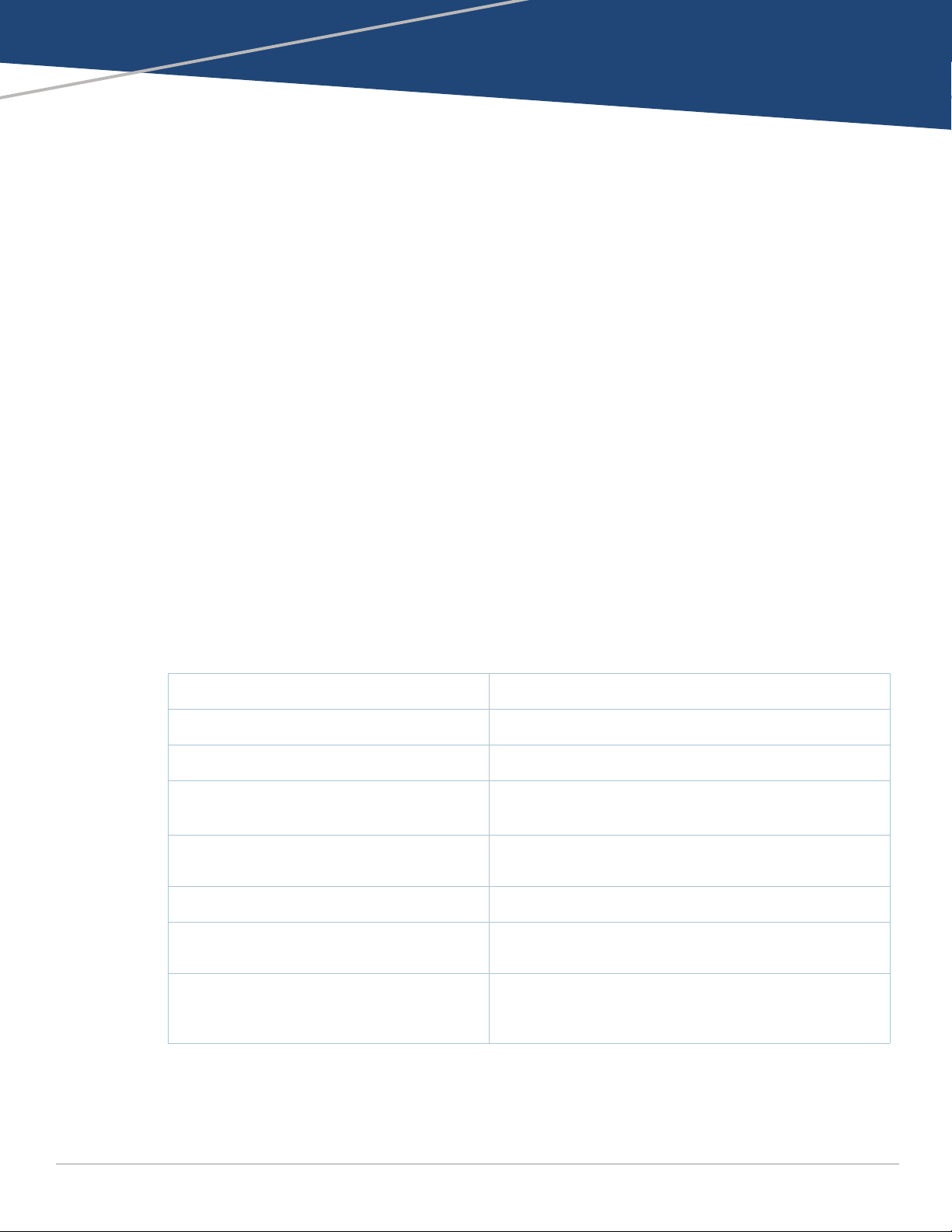
Contacting Support
Table 1 Contact Information
Main Site www.arubanetworks.com
Support Site http://support.arubanetworks.com
Airheads Social Forums and Knowledge Base www.community.arubanetworks.com
North American Telephone 1-800-943-4526 (Toll Free)
1-408-754-1200
International Telephones https://www.arubanetworks.com/support-services/contact-
Software Licensing Site www.hpe.com/networking/support
End of Support information www.arubanetworks.com/support-services/end-of-life/end-
support/
of-life-policy/
Security Incident Response Team (SIRT) Site: https://www.arubanetworks.com/support-services/
security-bulletins/
Email: aruba-sirt@hpe.com
Aruba 9004 Gateway | Installation Guide Preface | 5
Page 6

6 |Preface Aruba 9004 Gateway | Installation Guide
Page 7
Chapter 1
9004 Gateway
The Aruba 9004 gateway is a wireless LAN gateway that connects, controls, and intelligently
integrates wireless Access Points (APs), Managed Devices, and Air Monitors (AMs).
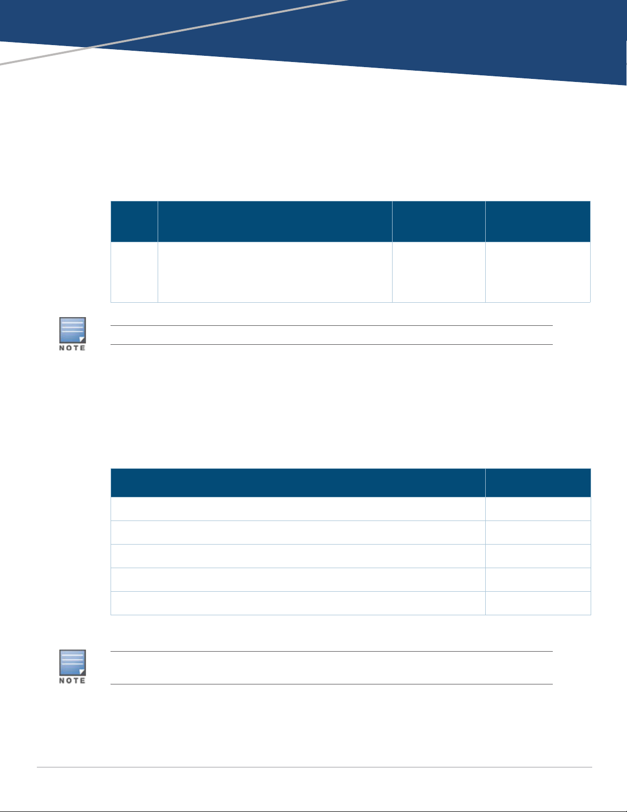
The Aruba 9004 gateway has the following port configuration:
Table 2 Aruba 9004 Gateway Port Configuration
Model Ports
9004 4 x 100/1000BASE-T ports
1 x USB 3.0 port
RJ45 console port
Micro USB console port
The Aruba 9004 gateway requires ArubaOS 8.5.0.0 or later versions.
Number of APs
Supported
32 2000
Number of Users
Supported
Package Checklist
Inform your supplier if there are any incorrect, missing, or damaged parts. To return this product,
repack this unit and other materials included into the original packaging, before returning it to the
supplier.
Table 3 Package Contents
Item Quantity
Aruba 9004 gateway 1
Micro USB console cable 1
Power adapter 1
Aruba 9004 Start-up Guide (Printed) 1
Adapter cable saddle 1
Optional accessories are available for use with the Aruba 9004 gateway and are sold separately. Contact your
Aruba sales representative for details and assistance.
Aruba 9004 Gateway Components
This section introduces the different component and its location in the Aruba 9004 gateway.
Aruba 9004 Gateway | Installation Guide 9004 Gateway | 7
Page 8

Figure 1 shows the front panel of the Aruba 9004 gateway and Figure 2 shows the back panel of
the Aruba 9004 gateway.
Figure 1 Front Panel of the Aruba 9004 gateway
* The antenna is integrated within the hardware and is not displayed on the front panel.
Figure 2 Back Panel of the Aruba 9004 gateway
Front Panel LEDs
The front panel LEDs show the System, WAN, and LAN status including various other features.
These front panel LEDs provide basic monitoring information of the overall status of the Aruba
9004 gateway. The following table describes the LED indicators and their corresponding status:
Table 4 LED Status
LED Function Indicator Status
System System status Green (Solid) Powered and Operational
Green (Blinking) Loading Software
Amber (Solid) Critical Alarm
Amber (Blinking) Major Alarm
Off Power Off
WAN Link Status Green (Solid) All WAN Ports Established
Amber (Solid) No WAN Ports Established
LAN Link Status Green (Solid) All LAN Ports Established
Amber (Solid) No LAN Ports Established
8 | 9004 Gateway Aruba 9004 Gateway | Installation Guide
Page 9

Table 4 LED Status
LED Function Indicator Status
Wireless Wireless LAN
Controller Status
Central/Cloud Central Connectivity Status
Cellular Link Status Green (Solid) Modem Initialized and Connected to
Green (Solid) The WLAN Controller is Up and
Green (Blinking) WLAN Gateway Booting
Green (Blinking) Modem Initializing
Green + Amber (Greenish
Yellow) (Solid)
Amber (Solid) Modem Initialized and Connected to
Amber (Blinking) Network Connection Failure. SIM
Functioning.
the Network. Good Signal Strength.
Signal Strength Threshold:
> -65 dBm
Modem Initialized and Connected to
the Network. Average Signal Strength.
Signal Strength Threshold:
< -65 dBm
> -80 dBm
the Network. Poor Signal Strength.
Signal Strength Threshold:
< -80 dBm
Removal. Modem not Responding to
Web Commands.
Red (Solid) Modem Lost IP Address or
Red (Blinking) Hardware Failure. USB Failure.
Disconnected from the Network.
Acting as a Backup Uplink.
Unsupported USB Device Attached.
DC Power Connector
The AC-DC adapter kit with the following specification is used to power the Aruba 9004 gateway:
12V/2A power interface
Center-positive 2.1/5.5 mm circular plug, 9.5 mm length
Reset Switch
The Aruba 9004 gateway includes a recessed button for resetting the gateway configurations.
Insert a pin into the Reset Switch hole until you feel the pin touches a surface. Push and hold the
pin for two seconds to reset the controller configuration.
Ethernet Ports
The Aruba 9004 gateway is equipped with four 100/1000BASE-T Gigabit Ethernet ports (0 to 3).
Gigabit Ethernet uses all eight wires and each pair is bidirectional, which means, the same pair is
used for both data transmission and reception. Figure 3 illustrates the Gigabit Ethernet port pin-
Aruba 9004 Gateway | Installation Guide 9004 Gateway | 9
Page 10

out for an RJ-45 connector. The pins paired on a 100/1000Base-T Gigabit Ethernet port are: 1/2, 3/
1000Base-T Gigabit
Ethernet Port
RJ-45 Female
Pin-Out
Signal Name
1
2
3
4
5
6
7
8
BI_DC+
BI_DC-
BI_DD+
BI_DD-
BI_DA+
BI_DABI_DB+
BI_DB-
Function
Bi-directional pair +C
Bi-directional pair -C
Bi-directional pair +D
Bi-directional pair -D
Bi-directional pair +A
Bi-directional pair -A
Bi-directional pair +B
Bi-directional pair -B
6, 4/5, and 7/8.
Figure 3 Figure 3 Gigabit Ethernet Port Pin-Out
Ethernet Port LEDs
Each 100/1000BASE-T Ethernet port is equipped with two LEDs that allow basic monitoring of
link/port status and activity.
LINK/ACT: Placed on the left side of the port, and displays the link status and activity of the
port.
STATUS: Placed on the right side of the port, and displays the status of the port based on the
CLI.
The following table describes the LED behavior for each mode:
Table 5 100/1000BASE-T Ethernet Port LEDs
LED Function Mode Indicator Status
LINK/ACT Link status NA Green (Solid) Link established
Green (Blinking) Port is transmitting or receiving
data
Off No link
STATUS Port status Speed Green (Solid) Link at 1000 Mbps
Off Link at 100 Mbps
Micro-USB Console Port
The Aruba 9004 gateway is equipped with a Micro-USB (type B) connector that provides console
access for direct local access. If both Micro-USB and RJ-45 console ports are connected, the MicroUSB connection takes precedence over the RJ-45 console connection.
Micro-USB Driver
To use the Micro-USB console port, you must install the Aruba Micro-USB driver on the computer
that will manage your gateway. To download the driver, perform the following steps:
1. Go to https://support.arubanetworks.com.
2. Click on the Tools & Resources tab.
10 | 9004 Gateway Aruba 9004 Gateway | Installation Guide
3. Open the USB Console Driver folder.
4. Open the Mobility Gateway and Mobility Access Switch folder.
Page 11

Select the appropriate file for your application. The corresponding operating system is in the file
3
4
5
2
5
63
RJ-45 DB-9
Internal
Connections
TxD
GND
RxD
1
2
3
4
5
6
7
8
TxD
GND
RxD
RJ-45 Female
Pin-Out
DB-9 Male
Pin-Out
TxD
RxD
Ground
5
4
3
2
1
9
8
7
6
name.
Serial
Console Port
Console Port
The serial console port allows connecting a gateway to a serial terminal or a laptop for direct local
management. This port is a RJ-45 female connector with the pin-outs descried in Figure 4 on page
12. Connect it directly to a terminal or terminal server using an Ethernet cable.
Figure 4 Serial Console Port Pin-Out
RJ-45 Female
Pin-Out
1
2
3
4
5
6
7
8
Direction
Input
Output
TxD
GND
GND
RxD
The communication settings for the Console port is shown in the following table:
Table 6 Console Terminal Settings
Baud Rate Data Bits Parity Stop Bits Flow Control
9600 8 None 1 None
The CONSOLE port is compatible only with RS-232 devices. Non-RS-232 devices, such as APs, are not supported.
Do not connect the Console port to an Ethernet switch or a PoE power source. This may damage the gateway.
Serial Console Port Adapter
A modular adapter can be used to convert the female RJ-45 connector to a male DB9 connector.
See Figure 5 for complete details.
Figure 5 RJ-45 (Female) to DB9 (Male) Modular Adapter Conversion
USB Port
The Aruba 9004 gateway is equipped with a USB 3.0 interface. A USB storage device can be used
to save and upload configurations to the gateway.
Kensington Lock Slot
The Aruba 9004 gateway is equipped with a Kensington security slot for additional security.
Aruba 9004 Gateway | Installation Guide 9004 Gateway | 11
Page 12

12 | 9004 Gateway Aruba 9004 Gateway | Installation Guide
Page 13

Chapter 2
Installation
Installation of the device should be performed by a trained installation professional.
Installation Recommendations
For proper air circulation, leave at least 10 cm (4 inches) clearance on the left, right, front, and rear
side of the gateway.
Leave additional space in front and rear side of the gateway to access power cords, network
cables, and indicator LEDs.
Avoid placing anything on top of the gateway because it can lead to overheating of the gateway.
Avoid placing this gateway on any other device because the heat dissipated from the other device
can over heat the gateway.
Installation Using the Integrated Wall-Mounting Slots
The keyhole-shaped slots on the bottom of the gateway can be used to attach the device upright
(back port facing downwards) to an indoor wall or shelf.
Make sure to mount the gateway in such a way that there is a clear path to the Ethernet port, such as
a predrilled hole in the mounting surface.
1. At the mounting location, install two screws on the wall or shelf, 145.35 mm apart. If you are
attaching the device to drywall, it is recommended that you use appropriate wall anchors (not
included). See Figure 6.
Use 3/4 inch long #6 pan head wood screws for mounting 9004 unit on wood.
Use 3/4 inch long #6 pan head wood screws with plastic screw anchor #6-8 x 1 inch on dry wall
or concrete wall.
Required quantity: 2 screws per unit
Figure 6 Mounting Using the Integrated Wall-Mounting Slots
Aruba 9004 Gateway | Installation Guide Installation | 15
Page 14

2. Align the mounting slots on the bottom of the gateway over the screws and slide the unit into
place. See Figure 7
Figure 7 Wall Mounting Aruba 9004 Gateway
3. Align the cable saddle with the slot on the side of the gateway and push the cable saddle into the
unit to secure it. See Figure 8.
Figure 8 Attaching a cable saddle
4. Insert the cable into the cable saddle and attach it to the power connector slot. This secures the
cable and keeps it in place.See Figure 9.
16 |Installation Aruba 9004 Gateway | Installation Guide
Page 15

Figure 9 Securing a cable
Aruba 9004 Gateway | Installation Guide Installation | 17
Page 16

18 |Installation Aruba 9004 Gateway | Installation Guide
Page 17

Chapter 3
Specifications, Safety, and
Compliance
Aruba 9004 Gateway Specifications
Physical
Device Dimensions (without mounting brackets) (HxWxD): 3.82 cm x 19.85cm x 15.31 cm
Device Weight: 2.723 lbs (1.235 kg)
Electrical
Ethernet
4 x 100/1000BASE-T auto-sensing Ethernet RJ-45 Interfaces
MDI/MDX
Power
12V DC power interface, supports powering through an 12V DC, 2.5A AC-to-DC power adapter.
Environmental
Operating
Temperature Range: 0 °C to 40 °C (32 °F to 104 °F)
Humidity Range: 10% to 90% (RH), non-condensing
Storage and Transportation
Temperature Range: –40 °C to 70 °C (–40 °F to 158 °F)
Humidity Range: 10% to 95% (RH), non-condensing
For additional specifications on this product, please refer to the data sheet. The data sheet can be
found at www.arubanetworks.com
Safety and Regulatory Compliance
Aruba Networks, a Hewlett Packard Enterprise company provides a multi-language document that
contains country-specific restrictions and additional safety and regulatory information for all Aruba
products. This document can be viewed or downloaded from the following location:
www.arubanetworks.com/safety_addendum
Aruba gateways must be installed by a professional installer. The professional installer is responsible for
ensuring that grounding is available and it meets applicable local and national electrical codes.
RF Radiation Exposure Statement: This equipment complies with RF radiation exposure limits. This equipment
should be installed and operated with a minimum distance of 13.78 inches (35cm) between the radiator and
your body for 2.4 GHz and 5 GHz operations. This transmitter must not be co-located or operating in
conjunction with any other antenna or transmitter.
Aruba 9004 Gateway | Installation Guide Specifications, Safety, and Compliance | 19
Page 18

Déclaration sur les limites d'exposition aux radiofréquences : cet équipement est conforme aux limites
d'exposition aux rayonnements radioélectriques spécifiées. Il doit être installé et utilisé à une distance
minimale de 35 cm par rapport à votre corps pour les fréquences de 2,4 et 5 GHz. Cet émetteur-récepteur ne
doit pas être utilisé ou situé à proximité d'autres antennes ou émetteurs-récepteurs.
FCC Class B Part 15
This device complies with Part 15 of the Federal Communications Commission (FCC) Rules. Operation
is subject to the following two conditions:
This device may not cause harmful interference.
This device must accept any interference received, including interference that may cause
undesired operation.
Changes or modifications to this unit not expressly approved by Aruba Networks, a Hewlett Packard Enterprise
company could void the user’s authority to operate this equipment.
This equipment has been tested and found to comply with the limits for a Class B digital device,
pursuant to Part 15 of the FCC Rules. This equipment generates, uses and can radiate radio
frequency energy and, if not installed and used in accordance with the manufacturer’s instructions,
may cause interference harmful to radio communications.
If this equipment does cause interference, which can be determined by turning the equipment off
and on, the user is encouraged to try to correct the interference by one or more of the following
measures:
Reorient or relocate the receiving antenna.
Increase the separation between the equipment and receiver.
Connect the equipment to an outlet on a circuit different from that to which the receiver is
connected.
Consult the dealer or an experienced radio or TV technician for help.
Industry Canada
This Class B digital apparatus meets all of the requirements of the Canadian Interference-Causing
Equipment Regulations.
This device complies with Industry Canada's license-exempt RSS regulations. Operation of this device
is subject to the following two conditions: (1) this device may not cause interference, and (2) this
device must accept any interference, including interference that may cause undesired operation.
Déclaration d’Industrie Canada
Conformément aux réglementations d’Industrie Canada, cet émetteur-récepteur radio doit être
utilisé uniquement avecune antenne dont le type et le gain maximal doivent être approuvés par
Industrie Canada.
Ce périphérique est conforme aux règlements RSS exempts de licence d’Industrie Canada.
L’utilisation de ce périphérique est soumise aux deux conditions suivantes : (1) ce périphérique ne
doit pas provoquer d’interférences, et (2) ce périphérique doit accepter toute interférence, y compris
les interférences susceptibles de provoquer undysfonctionnement.
20 | Specifications, Safety, and Compliance Aruba 9004 Gateway | Installation Guide
Page 19

EU Regulatory Conformance
The Declaration of Conformity made under RED Directive 2014/53/EU is available for
viewing at http://www.hpe.com/eu/certificates. Select the document that corresponds to
your device’s model number as it is indicated on the product label.
Use of controls or adjustments of performance or procedures other than those specified in this manual may
result in hazardous radiation exposure.
Although this gateway has been tested up to 1 kV per CE immunity requirements, it requires surge protection
to be provided as part of the building installation to protect against unidirectional surges resulting from
electrical switching and lightning strikes.
For protection against these surges in an outdoor installation, any exposed wiring must be shielded, and the
shield for the wiring must be grounded at both ends.
Wireless Channel Restrictions
Table 7 Frequency Range Table
Frequency Range MHz Max EIRP
2402-2480 -8 dbm
Battery Statements
Il y a danger d’explosion s’il y a remplacement incorrect de la batterie.
Remplacer uniquement avec une batterie due même type ou d’un équivalent recommandé par le
constructeur.
Mettre au rebut les batteries usagées conformément aux unstruction du fabricant.
The battery supplied with this product may contain perchlorate material. Special handling may apply in
California and certain other states. See www.dtsc.ca.gov/hazardouswaste/perchlorate for more information.
There is a risk of explosion if battery is replaced by an incorrect type, so dispose used batteries according to
the instructions.
Japan VCCI
This product is a Class B product based on the standard of the VCCI Council. If this is used near a
radio or television receiver in a domestic environment, it may cause radio interference. Install and
use the equipment according to the instruction manual.
Regulatory Model Name
The regulatory model name for the Aruba 9004 Gateway is ARCN9004.
Aruba 9004 Gateway | Installation Guide Specifications, Safety, and Compliance | 21
Page 20

Proper Disposal of Aruba Equipment
10
᳝↦᳝ᆇ⠽䋼ໄᯢ
Hazardous Materials Declaration
᳝↦᳝ᆇ⠽䋼ܗ㋴(Hazardous Substance)
䚼ӊৡ⿄
(Parts)
䪙
3E
∲
+J
䬝
&G
݁Ӌ䫀
&U
⒈㘨㣃
3%%
⒈Ѡ㣃䝮
3%'(
⬉䏃ᵓ
(
PCA Boards)
hƻ ƻ ƻ ƻ ƻ
ᴎẄ㒘ӊ
(
Mechanical Sub-Assemblies)
hƻ ƻ ƻ ƻ ƻ
ƻ˖
㸼⼎䆹᳝↦᳝ᆇ⠽䋼䆹䚼ӊ᠔᳝ഛ䋼ᴤ᭭Ёⱘ䞣ഛ
SJ/T11363-2006
ޚ㾘ᅮⱘ䰤䞣㽕∖ҹϟDŽ
Indicates that the concentration of the hazardous substance in all homogeneous materials in the parts is
below the relevant threshold of the SJ/T11363-2006 standard.
h˖ 㸼⼎䆹᳝↦᳝ᆇ⠽䋼㟇ᇥ䆹䚼ӊⱘᶤϔഛ䋼ᴤ᭭Ёⱘ䞣䍙ߎ6-7ޚ㾘ᅮⱘ䰤䞣㽕∖DŽ
Indicates that the concentration of the hazardous substance of at least one of all homogeneous materials
in the parts is above the relevant threshold of the SJ/T11363-2006 standard.
ᇍ䫔ଂП᮹ⱘ᠔ଂѻકᴀ㸼ᰒ⼎կᑨ䫒ⱘ⬉ᄤֵᙃѻકৃ㛑ࣙ䖭ѯ⠽䋼DŽ
This table shows where these substances may be found in the supply chain of electronic information
products, as of the date of sale of the enclosed product.
ℸᖫЎ䩜ᇍ᠔⍝ঞѻકⱘ⦃ֱՓ⫼ᳳᖫᶤѯ䳊䚼ӊӮ᳝ϔϾϡৠⱘ⦃ֱՓ⫼ᳳ
՟བ⬉∴ܗഫ䌈݊ѻકϞ
ℸ⦃ֱՓ⫼ᳳ䰤া䗖⫼ѢѻકᰃѻકݠЁ᠔㾘ᅮⱘᴵӊϟᎹ
The Environment- Friendly Use Period (EFUP) for all enclosed products and their parts are
per the symbol shown here. The Environment- Friendly Use Period is valid only when the
product is operated under the conditions defined in the product manual.
Waste of Electrical and Electronic Equipment
Aruba Networks, a Hewlett Packard Enterprise company products at end of life are
subject to separate collection and treatment in the EU Member States, Norway, and
Switzerland and therefore are marked with the symbol shown at the left (crossed-out
wheelie bin). The treatment applied at end of life of these products in these countries
shall comply with the applicable national laws of countries implementing Directive
2012/19/EU on Waste of Electrical and Electronic Equipment (WEEE).
European Union RoHS
Aruba Networks, a Hewlett Packard Enterprise company products also comply
with the EU Restriction of Hazardous Substances Directive 2011/65/EU (RoHS).
EU RoHS restricts the use of specific hazardous materials in the manufacture of
electrical and electronic equipment. Specifically, restricted materials under the
RoHS Directive are Lead (including Solder used in printed circuit assemblies), Cadmium, Mercury,
Hexavalent Chromium, and Bromine. Some Aruba products are subject to the exemptions listed in
RoHS Directive Annex 7 (Lead in solder used in printed circuit assemblies). Products and packaging
will be marked with the “RoHS” label shown at the left indicating conformance to this Directive.
India RoHS
This product complies with RoHS requirements as prescribed by E-Waste (Management & Handling)
Rules, governed by the Ministry of Environment & Forests, Government of India.
China RoHS
Aruba Networks, a Hewlett Packard Enterprise company products also comply with
China environmental declaration requirements and are labeled with the “EFUP 10”
label shown at the left.
22 | Specifications, Safety, and Compliance Aruba 9004 Gateway | Installation Guide
Page 21

Korean
Taiwan
所有技術文件皆必須秀出廠牌 / 型號,而使用手冊必須再補上警語,其警語?容如下:依據低功電波射性電機管辦法
第十二條
※ 經型式認證合格之低功?射頻電機,非經許可,公司、商號或使用者均?得擅自
變頻、加大功或變原設計之特性及功能。
第十四條
※ 低功射頻電機之使用?得影響飛航安全及干擾合法通信;經發現有干擾現象時,應即停用,並改善至無干擾時方得繼
續使用。
- 前項合法通信,指依電信法規定作業之無線電通信。
- 低功射頻電機須忍受合法通信或工業、科學及醫?用電波?射性電機設備之干擾。
支援 5G 功能則必須補上 " 應避免影響附近雷達系統之操作 "
不具備外接或替換天線時須加註: " 高增益指向性天線只得應用於固定式點對點系統。
第十二條 經型式認證合格之低功率射頻電機,非經許可,公司、商號或使用者均不得擅自變更頻率、加大功率或變
更原設計之特性及功能。
第十四條 低功率射頻電機之使用不得影響飛航安全及干擾合法通信;經發現有干擾現象時,應立即停用,並改善至
無干擾時方得繼續使用。
前項合法通信,指依電信法規定作業之無線電通信。
低功率射頻電機須忍受合法通信或工業、科學及醫療用電波輻射性電機設備之干擾。
1. 應避免影響附近雷達系統之操作。
2. 高增益指向性天線只得應用於固定式點對點系統
3. 電磁波暴露量 MPE 標準值 1 mW/cm2, 送測產品實測值為 : 0.46mW/cm2
Нормативные требования Евразийского Экономического Союза
Russia
HPE Russia: ООО "Хьюлетт Паккард Энтерпрайз" Российская Федерация, 125171, г.
Москва, Ленинградское шоссе, 16А, стр.3, Телефон: +7 499 403 4248 Факс: +7 499 403
4677
'HPE Belarus': ИООО «Хьюлетт-Паккард Бел», Республика Беларусь, 220030, г. Минск,
ул. Интернациональная, 36-1, Телефон/факс: +375 17 392 28 20
'HPE Kazakhstan': TOO «Хьюлетт-Паккард (К)», Республика Казахстан, 050040, г.
Алматы, Бостандыкский район, проспект Аль-Фараби, 77/7, Телефон/факс: + 7 727 355 35 50
Kazakhstan
ЖШС "Хьюлетт Паккард Энтерпрайз" Ресей Федерациясы, 125171, Мәскеу, Ленинград тас жолы, 16A блок
3, Телефон: +7 499 403 4248 Факс: +7 499 403 4677
«HEWLETT-PACKARD Bel» ЖШС, Беларусь Республикасы, 220030, Минск қ., Интернациональная көшесі, 36/
1, Телефон/факс: +375 17 392 28 20
ЖШС «Хьюлетт-Паккард (К)», Қазақстан Республикасы, 050040, Алматы к., Бостандык ауданы, Әл-Фараби
даңғ ылы, 77/7, Телефон/факс: +7 (727) 355 35 50
Mexico
La operación de este equipo está sujeta a las siguientes dos condiciones: (1) es posible que este equipo o
dispositivo no cause interferencia perjudicial y (2) este equipo o dispositivo debeaceptar cualquier interferencia,
Aruba 9004 Gateway | Installation Guide Specifications, Safety, and Compliance | 23
Page 22

incluyendo la que pueda causar su operación no deseada.
24 | Specifications, Safety, and Compliance Aruba 9004 Gateway | Installation Guide
 Loading...