

Page 1

HPE Apollo 4510 Gen10 Chassis Setup and Installation Guide
Abstract
This document contains setup, installation, and configuration information for the HPE Apollo
4510 Gen10 Chassis. This document is for the person who installs, administers, and
troubleshoots servers and storage systems. Hewlett Packard Enterprise assumes you are
qualified in the servicing of computer equipment and trained in recognizing hazards in
products with hazardous energy levels.
Part Number: 881305-003
Published: April 2019
Edition: 3
Page 2

©
Copyright 2017, 2019 Hewlett Packard Enterprise Development LP
Notices
The information contained herein is subject to change without notice. The only warranties for Hewlett
Packard Enterprise products and services are set forth in the express warranty statements accompanying
such products and services. Nothing herein should be construed as constituting an additional warranty.
Hewlett Packard Enterprise shall not be liable for technical or editorial errors or omissions contained
herein.
Confidential computer software. Valid license from Hewlett Packard Enterprise required for possession,
use, or copying. Consistent with FAR 12.211 and 12.212, Commercial Computer Software, Computer
Software Documentation, and Technical Data for Commercial Items are licensed to the U.S. Government
under vendor's standard commercial license.
Links to third-party websites take you outside the Hewlett Packard Enterprise website. Hewlett Packard
Enterprise has no control over and is not responsible for information outside the Hewlett Packard
Enterprise website.
Acknowledgments
Microsoft® and Windows® are either registered trademarks or trademarks of Microsoft Corporation in the
United States and/or other countries.
Page 3

Contents
Planning the installation.........................................................................5
Identifying components and LEDs........................................................ 9
Verifying the pallet contents..........................................................................................................5
Warnings and cautions..................................................................................................................5
Space and airflow requirements................................................................................................... 6
Temperature requirements............................................................................................................7
Power requirements......................................................................................................................7
Grounding requirements............................................................................................................... 7
Front panel components............................................................................................................... 9
Drive Drawer LEDs...........................................................................................................10
Server front panel components........................................................................................ 10
Server front panel LEDs and buttons............................................................................... 11
Rear panel components..............................................................................................................13
Power supply LEDs .........................................................................................................13
Management module components...................................................................................14
Management module LEDs..............................................................................................14
I/O module components................................................................................................... 15
I/O module LEDs..............................................................................................................15
PCIe slot definitions......................................................................................................... 16
PCIe slot and processor mapping.................................................................................... 16
HPE Smart Array E208i-p SR Gen10 Controller port identification..................................17
HPE Smart Array P408i-p SR Gen10 Controller port identification..................................17
HPE Smart Array P824i-p MR Gen10 Controller port identification................................. 18
LFF drive bay numbering............................................................................................................ 18
Low profile LFF drive LED definitions......................................................................................... 19
Installing the chassis ...........................................................................20
Setting up and installing the chassis...........................................................................................20
Disassembling the chassis..........................................................................................................20
Installing the chassis into the rack.............................................................................................. 26
Installing the system components into the chassis..................................................................... 30
Installing a server............................................................................................................. 30
Installing a hot-plug drive................................................................................................. 31
Installing a flex slot power supply.....................................................................................32
Installing the system fan...................................................................................................32
HPE Smart Storage Battery............................................................................................. 33
Installing the HPE Smart Storage Battery............................................................. 33
Installing a management module..................................................................................... 35
Installing an expansion board.......................................................................................... 35
Installing an I/O module................................................................................................... 38
Installing a fan louver....................................................................................................... 39
Installing the midplane assembly..................................................................................... 39
Cabling and powering up the chassis.................................................41
Connecting the Management module to the network with the iLO ports.................................... 41
3
Page 4

Connecting the optional HPE APM module................................................................................ 41
I/O module option cabling........................................................................................................... 42
HPE Smart Array E208i-p SR Gen10 Controller cabling................................................. 42
HPE Smart Array P408i-p SR Gen10 Controller cabling................................................. 43
HPE Smart Array P824i-p MR Gen10 Controller cabling.................................................45
Powering up the system..............................................................................................................47
Troubleshooting.................................................................................... 48
Important safety information ...................................................................................................... 48
Symbols on equipment.....................................................................................................48
Troubleshooting resources..........................................................................................................49
Specifications........................................................................................50
Environmental specifications ..................................................................................................... 50
Chassis specifications.................................................................................................................50
Power supply specifications........................................................................................................50
HPE 800W Flex Slot Platinum Hot-plug Low Halogen Power Supply..............................51
HPE 800W Flex Slot -48VDC Hot-plug Low Halogen Power Supply...............................51
HPE 800W Flex Slot Titanium Hot-plug Low Halogen Power Supply..............................53
HPE 800W Flex Slot Universal Hot-plug Low Halogen Power Supply.............................53
HPE 1600W Flex Slot Platinum Hot-plug Low Halogen Power Supply............................54
Hot-plug power supply calculations............................................................................................ 55
Environmental considerations.............................................................56
Communications interference..................................................................................................... 56
Electrostatic discharge................................................................................................................56
Preventing electrostatic discharge................................................................................... 56
Grounding methods to prevent electrostatic discharge....................................................56
Websites................................................................................................ 58
Support and other resources...............................................................59
Accessing Hewlett Packard Enterprise Support......................................................................... 59
Accessing updates......................................................................................................................59
Customer self repair....................................................................................................................60
Remote support.......................................................................................................................... 60
Warranty information...................................................................................................................60
Regulatory information................................................................................................................61
Documentation feedback............................................................................................................ 61
4
Page 5
Planning the installation
1
2
3
6
5
4
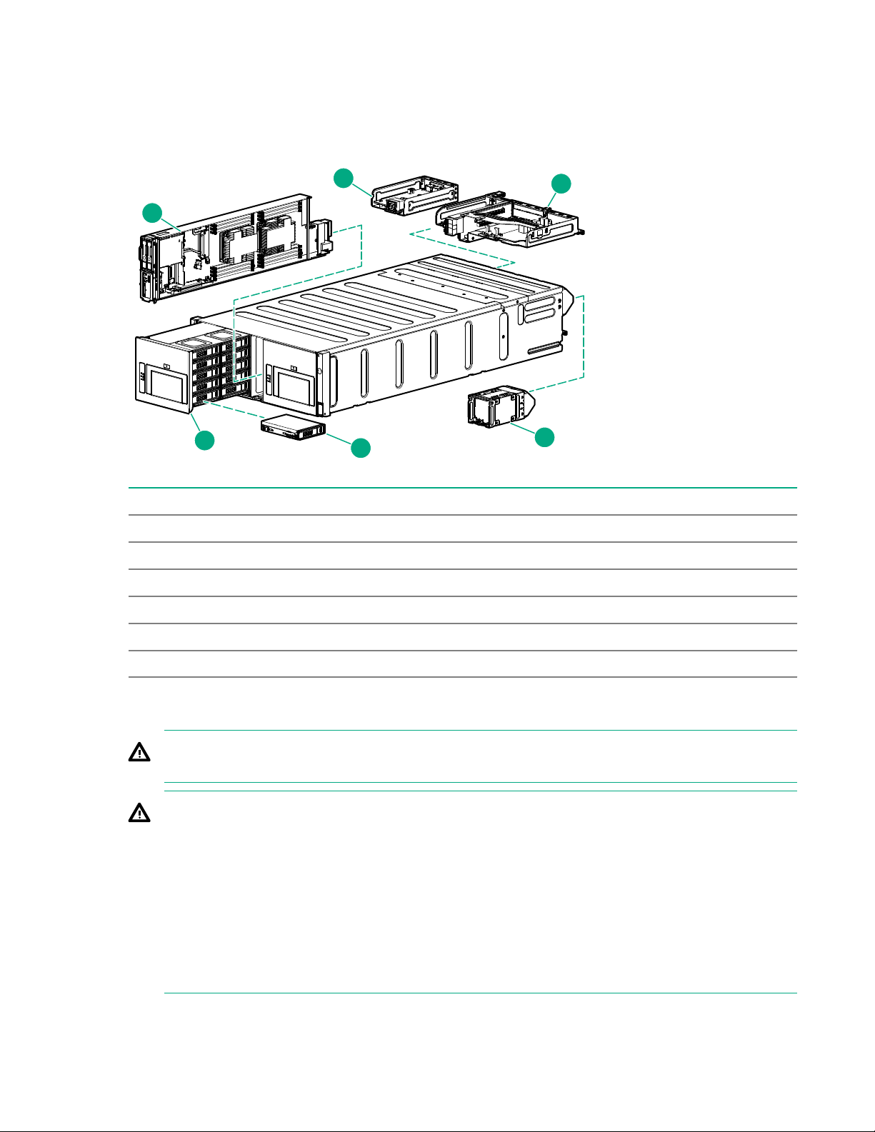
Verifying the pallet contents
Item Description
1 HPE ProLiant XL450 Gen10 Server
2 Management module
3 I/O module
4 System fan
5 LFF drive
6 Drive drawer
Warnings and cautions
WARNING: To reduce the risk of personal injury or damage to equipment, heed all warnings and
cautions throughout the installation instructions.
WARNING: To reduce the risk of personal injury or damage to the equipment, be sure that:
• The rack is bolted to the floor using the concrete anchor kit.
• The leveling feet extend to the floor.
• The full weight of the rack rests on the leveling feet.
• The racks are coupled together in multiple rack installations.
• Only one component is extended at a time. If more than one component is extended, a rack
might become unstable.
Planning the installation 5
Page 6
WARNING: To reduce the risk of personal injury or equipment damage, be sure that the rack is
adequately stabilized before installing the chassis.
WARNING: The chassis is very heavy. To reduce the risk of personal injury or damage to the
equipment, do the following:
• Observe local occupational health and safety requirements and guidelines for manual material
handling.
• Remove all installed components from the chassis before installing or moving the chassis.
• Get help to lift and stabilize the product during installation or removal, especially when the
product is not fastened to the rails. The chassis weighs more than 102.00 kg (225.00 lb), so at
least four people must lift the chassis into the rack together. An additional person may be
required to help align the chassis if the chassis is installed higher than chest level. If you are
using a mechanical lift to install the frame, two people are required to install the frame.
WARNING: To reduce the risk of personal injury or damage to the equipment, you must adequately
support the chassis during installation and removal.
WARNING: Be sure to install enclosures starting from the bottom of the rack and work your way up
the rack.
WARNING: To reduce the risk of personal injury from hot surfaces, allow the drives and the internal
system components to cool before touching them.
WARNING: To reduce the risk of electric shock or damage to the equipment:
• Never reach inside the chassis while the system is powered up.
• Perform service on system components only as instructed in the user documentation.
CAUTION: Always be sure that equipment is properly grounded and that you follow proper
grounding procedures before beginning any installation procedure. Improper grounding can result in
ESD damage to electronic components. For more information, see Electrostatic discharge on
page 56.
CAUTION: When performing non-hot-plug operations, you must power down the chassis and/or the
system. However, it may be necessary to leave the chassis powered up when performing other
operations, such as hot-plug installations or troubleshooting.
Space and airflow requirements
To enable servicing and ensure adequate airflow, observe the following spatial requirements when
deciding where to install a rack:
• Leave a minimum clearance of 121.9 cm (48.0 in) in front of the rack and between rows of racks.
• Leave a minimum clearance of 76.2 cm (30.0 in) in back of the rack for a single row of racks or after
the final row of racks.
Hewlett Packard Enterprise Rack products draw cool air in through the front and expel warm air through
the rear of the enclosure. Therefore, the front of the rack enclosure must be adequately ventilated to
6 Planning the installation
Page 7
enable ambient room air to enter the enclosure, and the rear of the enclosure must be adequately
ventilated to enable the warm air to escape from the enclosure.
IMPORTANT: Do not block the ventilation openings.
If the front of the rack is not completely filled with components, the remaining gaps between the
components can cause changes in the airflow, which can adversely affect cooling within the rack. Cover
these gaps with blanking panels.
CAUTION: Always use blanking panels to fill empty vertical spaces in the rack. This arrangement
ensures proper airflow. Using a rack without blanking panels results in improper cooling that can
lead to thermal damage.
Racks provide proper server cooling from flow-through perforations in the front and rear doors that
provide a 65% open area for ventilation.
Temperature requirements
To ensure continued safe and reliable equipment operation, install or position the rack in a well-ventilated,
climate-controlled environment.
The operating temperature inside the rack is always higher than the room temperature and is dependent
on the configuration of equipment in the rack. Check the TMRA for each piece of equipment before
installation.
CAUTION: To reduce the risk of damage to the equipment when installing third-party options:
• Do not permit optional equipment to impede airflow around the chassis or to increase the internal
rack temperature beyond the maximum allowable limits.
• Do not exceed the manufacturer’s TMRA.
Power requirements
Installation of this equipment must comply with local and regional electrical regulations governing the
installation of IT equipment by licensed electricians. This equipment is designed to operate in installations
covered by NFPA 70, 1999 Edition (National Electric Code) and NFPA-75, 1992 (code for Protection of
Electronic Computer/Data Processing Equipment). For electrical power ratings on options, refer to the
product rating label or the user documentation supplied with that option.
WARNING: To reduce the risk of personal injury, fire, or damage to the equipment, do not overload
the AC supply branch circuit that provides power to the rack. Consult the electrical authority having
jurisdiction over wiring and installation requirements of your facility.
CAUTION: Protect the chassis from power fluctuations and temporary interruptions with a regulating
UPS. This device protects the hardware from damage caused by power surges and voltage spikes
and keeps the chassis in operation during a power failure.
Grounding requirements
This equipment must be grounded properly for proper operation and safety. In the United States, you
must install the equipment in accordance with NFPA 70, 1999 Edition (National Electric Code), Article
250, as well as any local and regional building codes.
In Canada, you must install the equipment in accordance with Canadian Standards Association, CSA
C22.1, Canadian Electrical Code.
Planning the installation 7
Page 8

In all other countries, you must install the equipment in accordance with any regional or national electrical
wiring codes, such as the International Electrotechnical Commission (IEC) Code 364, parts 1 through 7.
Furthermore, you must be sure that all power distribution devices used in the installation, such as branch
wiring and receptacles, are listed or certified grounding-type devices.
Because of the high ground-leakage currents associated with this equipment, Hewlett Packard Enterprise
recommends the use of a PDU that is either permanently wired to the building’s branch circuit or includes
a nondetachable cord that is wired to an industrial-style plug. NEMA locking-style plugs or those
complying with IEC 60309 are considered suitable for this purpose. Using common power outlet strips to
supply power to this equipment is not recommended.
8 Planning the installation
Page 9
Identifying components and LEDs
1 1
2
3 4
5
6
7
88
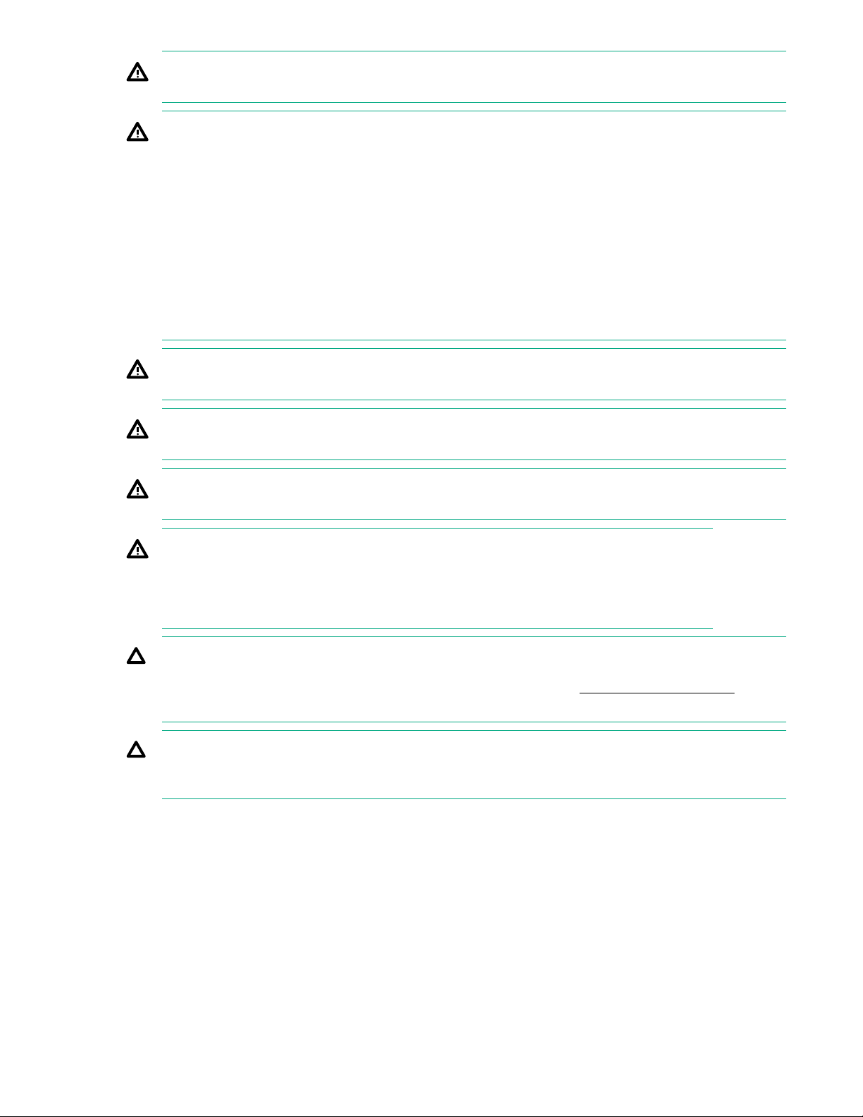
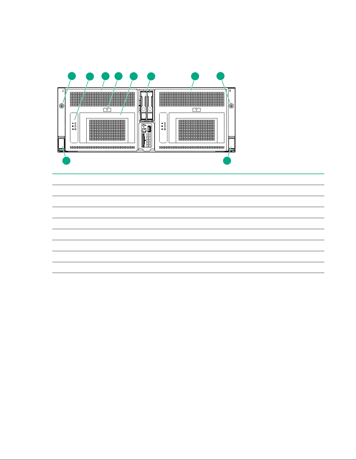
Front panel components
Item Specification
1 Bezel ear screws (2)
2 Drive drawer LEDs
3 Drive drawer 1
4 Drive drawer release button
5 Drive drawer release levers
6 Server bay
7 Drive drawer 2
8 Quick-release levers
Identifying components and LEDs 9
Page 10
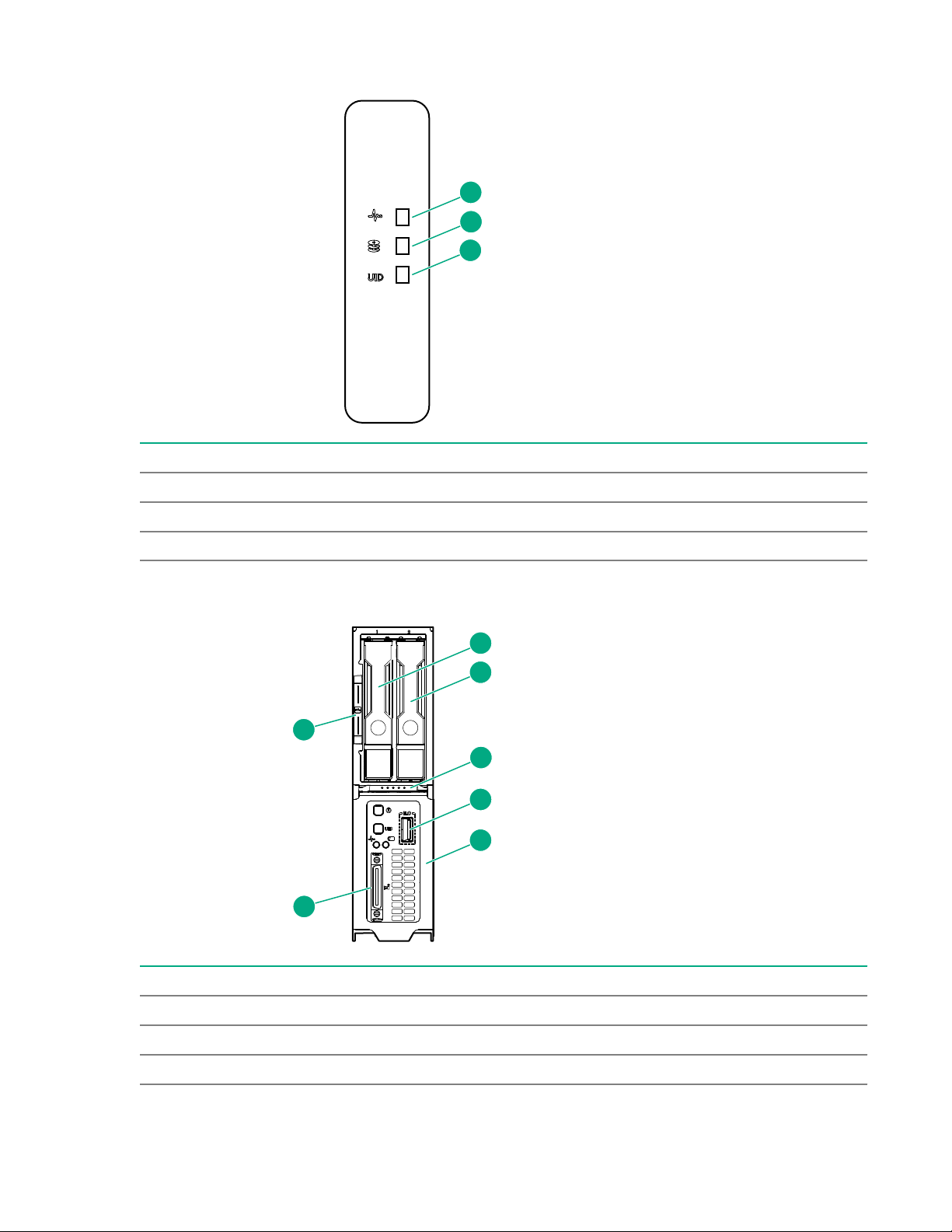
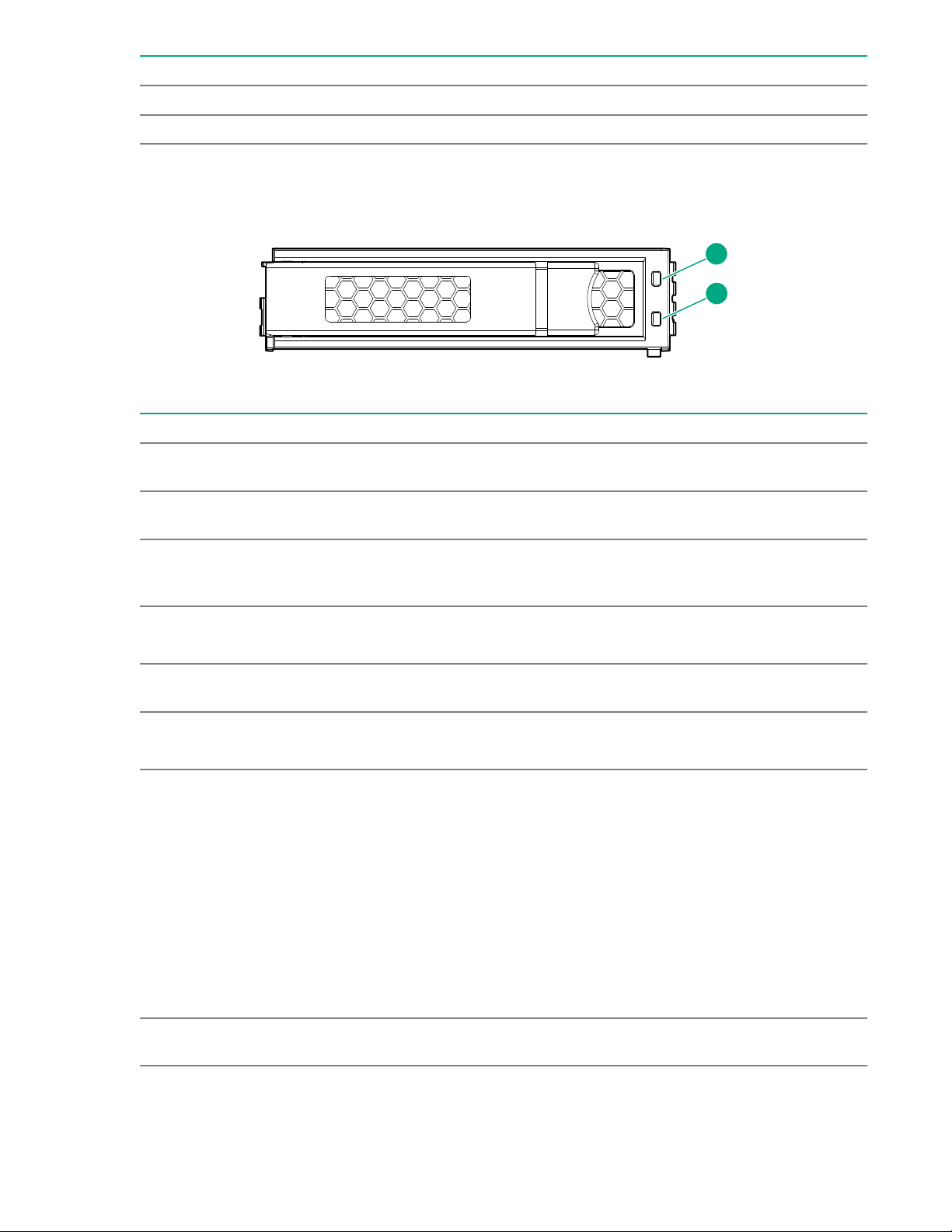
Drive Drawer LEDs
1
2
3
1
2
3
6
7
4
5
Item Specification
1 Backplane health LED
2 Drive health LED
3 UID LED
Server front panel components
Item Description
1 Drive bay 1
2 Drive bay 2
3 Server ejector button
Table Continued
10 Identifying components and LEDs
Page 11
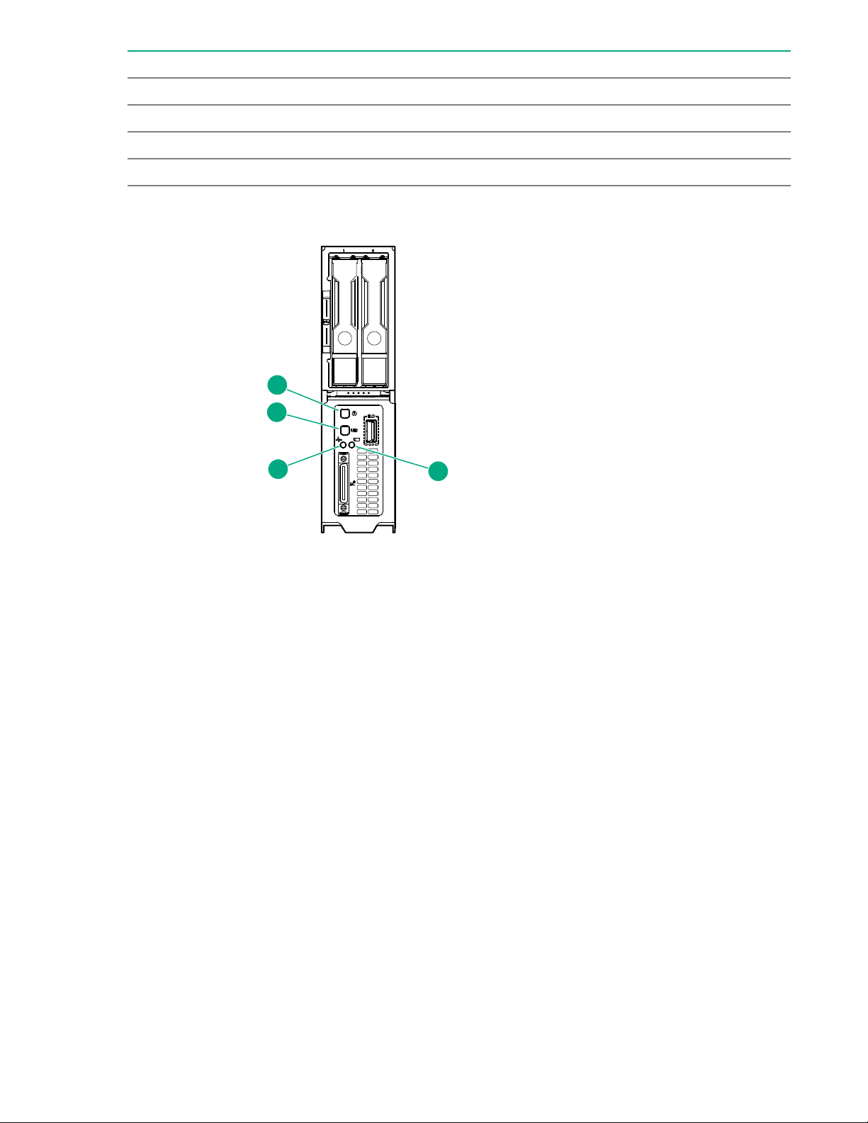
Item Description
1
2
4
3
4 iLO Service port
5 Server release lever
6 SUV cable connector
7 Serial label pull tab
Server front panel LEDs and buttons
Identifying components and LEDs 11
Page 12

Item Description Status
1 Power On/Standby
button and system
power LED
2 UID LED/button
Solid green = System on
Flashing green (1 Hz/cycle per sec) = Performing power on
sequence
Solid amber = System in standby
Off = No power present
Solid blue = Activated
Flashing blue:
• 1 Hz/cycle per sec = Remote management or firmware upgrade
in progress
• 4 Hz/cycle per sec = iLO manual reboot sequence initiated
• 8 Hz/cycle per sec = iLO manual reboot sequence in progress
• 1 fast flash and then off for 3 seconds = iLO Service Port status
is Complete
• 4 medium flashes and then off for 1 second = iLO Service Port
status is Busy
• 8 fast flashes and then off for 1 second = iLO Service Port status
is Error
3 Server health LED
4 Server backup LED
Off = Deactivated
Solid green = Normal
Flashing green (1 Hz/cycle per sec) = iLO is rebooting
Flashing amber = System degraded
Flashing red (1 Hz/cycle per sec) = System critical
Off = Normal operations. No backup in progress.
Flashing white = Backup in progress. Do not remove drives, nodes,
or associated system components, and do not power down the
server.
12 Identifying components and LEDs
Page 13
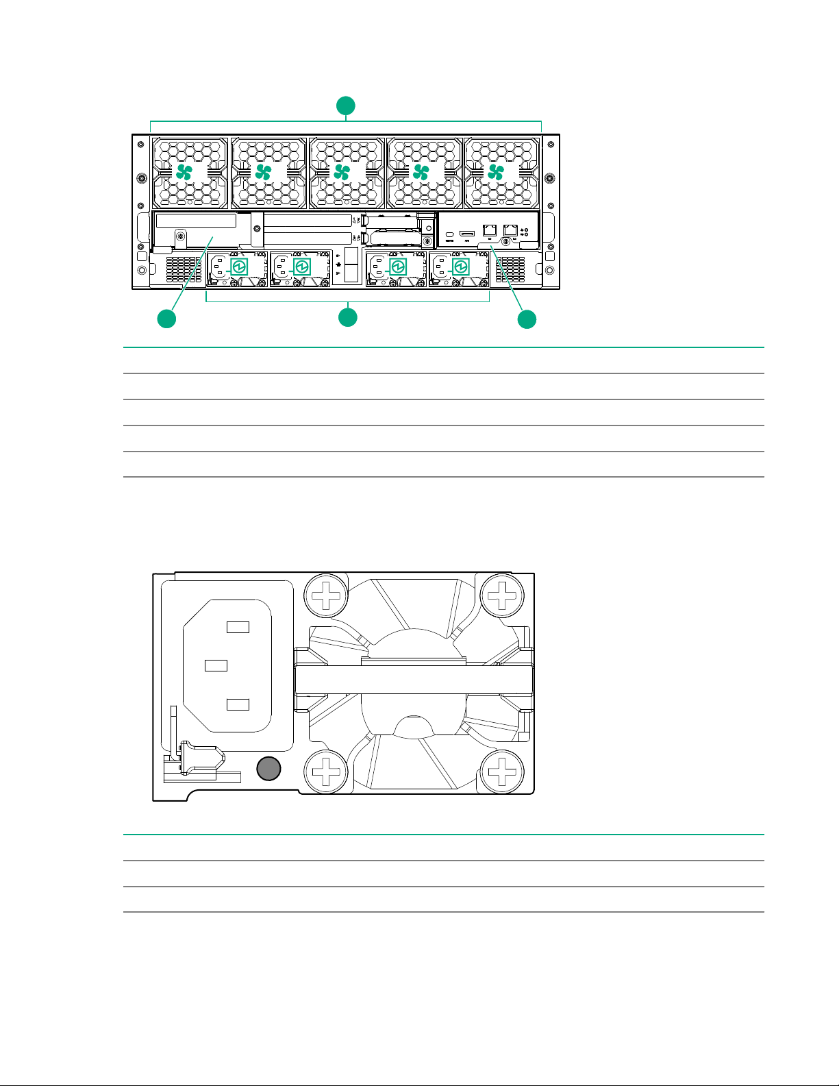
Rear panel components
1 2 3 4 5
1 2 3 4
1
2
3
4
Item Description
1 System fans
2 Management module
3 Power supply bays
4 I/O module
Power supply LEDs
The power supply LED is on each power supply.
LED Status Description
Off System is off or power supply has failed.
Solid Green Normal
Identifying components and LEDs 13
Page 14
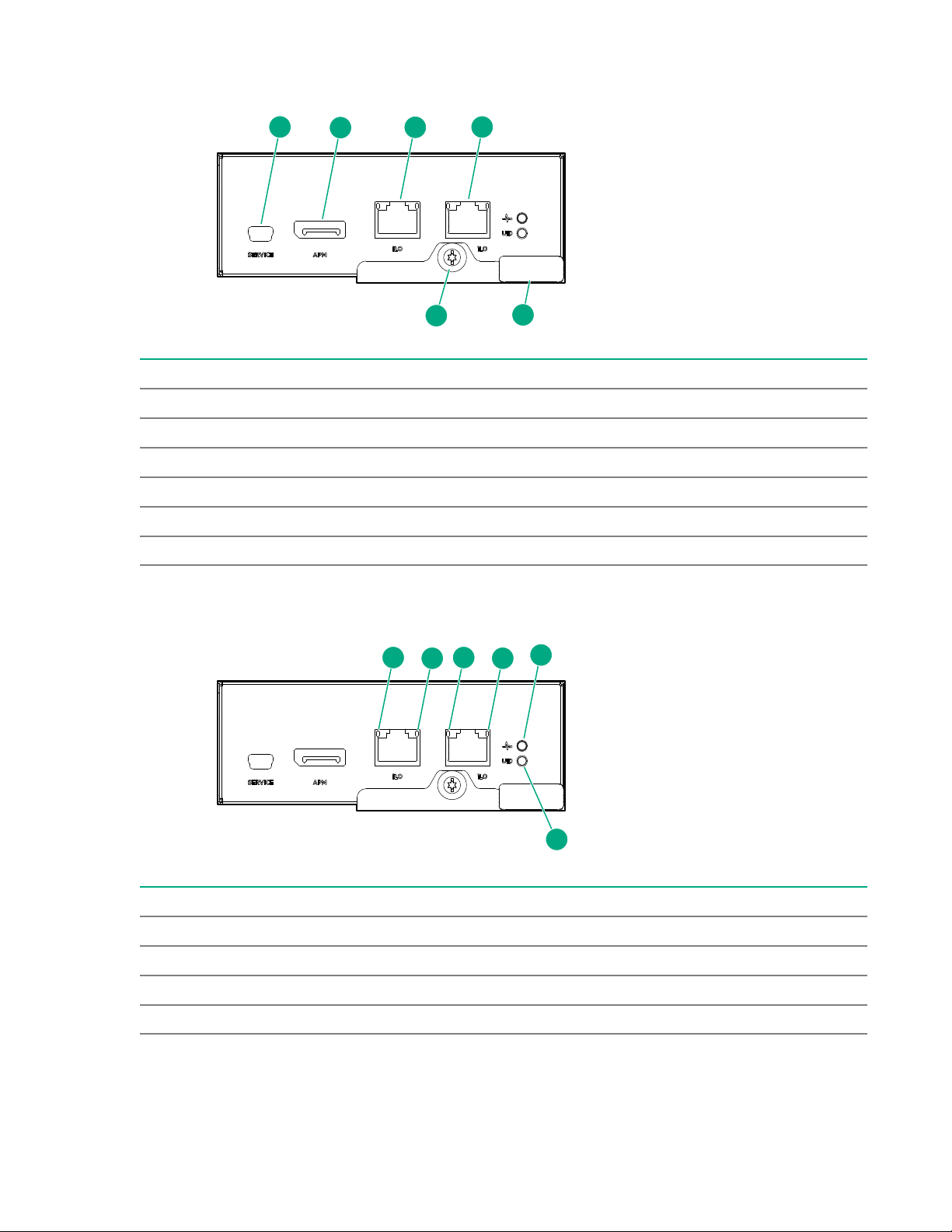
Management module components
1
6
2
3
4
5
1
2
1
2
3
4
Item Description
1 Reserved
2 APM connector
3 iLO port 1 (RJ-45)
4 iLO port 2 (RJ-45)
5 Management module release lever
6 Management module thumbscrew
Management module LEDs
Item Description
1 iLO (RJ-45) port link LEDs
2 iLO (RJ-45) port activity LEDs
3 Chassis health LED
4 Chassis UID LED
14 Identifying components and LEDs
Page 15
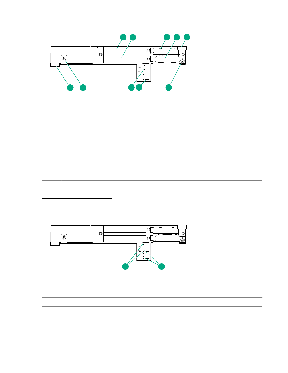
I/O module components
2
3
4 5
5
7
6 6
8
1
1 2
Item Description
1 PCIe slot 1
2 PCIe slot 2
3 PCIe slot 3
4 FlexLOM slot
5 I/O module release levers (2)
6 I/O module thumbscrews (2)
7 NIC port 2
8 NIC port 1
More information
PCIe slot and processor mapping on page 16
I/O module LEDs
Item Description
1 NIC activity LED
2 NIC link LED
Identifying components and LEDs 15
Page 16
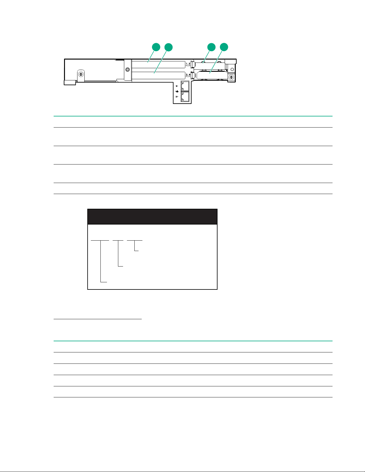
PCIe slot definitions
2
3
4
1
PCIe3 x8 (8,4,1)
Negotiable link width(s)
Physical connector link width
Gen 3 signaling rate
PCIe slot description
Item 2x/2x I/O module 3x/1x I/O module
1 PCIe expansion slot 1 — PCIe3 x16 (16, 8, 4,
2, 1)
2 PCIe expansion slot 2 — PCIe3 x16 (16, 8, 4,
2, 1)
3 PCIe expansion slot 3 — PCIe3 x16 (16, 8, 4,
2, 1)
4 FlexibleLOM slot — PCIe3 x8 (8, 4, 2, 1) FlexibleLOM slot — PCIe3 x8 (8, 4, 2, 1)
PCIe expansion slot 1 — PCIe3 x8 (8, 4, 2,
1)
PCIe expansion slot 2 — PCIe3 x8 (8, 4, 2,
1)
PCIe expansion slot 3 — PCIe3 x16 (16, 8,
4, 2, 1)
More information
PCIe slot and processor mapping on page 16
PCIe slot and processor mapping
PCIe slot 2x/2x I/O module 3x/1x I/O module
1 Processor 2 Processor 1
2 Processor 1 Processor 1
3 Processor 2 Processor 2
4 Processor 1 Processor 1
16 Identifying components and LEDs
Page 17
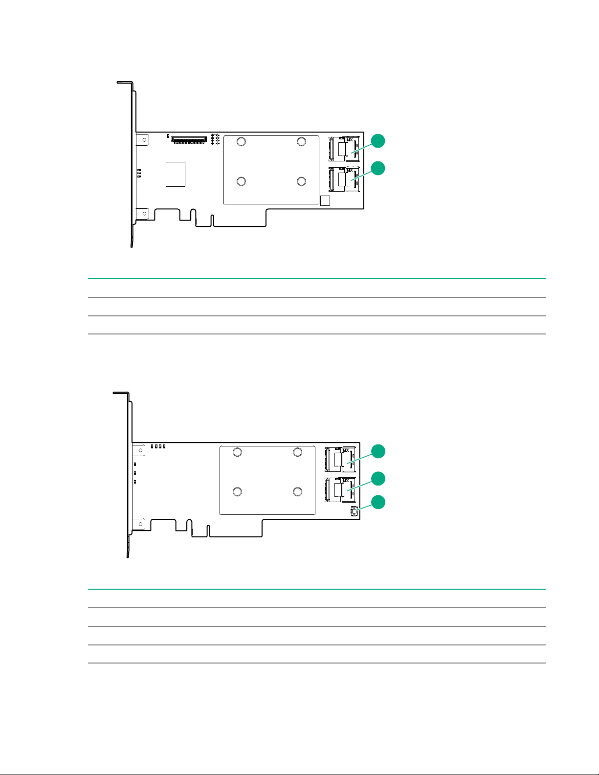
HPE Smart Array E208i-p SR Gen10 Controller port identification
1
2
1
2
3
Item Description
1 Internal x4 Mini SAS port 1
2 Internal x4 Mini SAS port 2
HPE Smart Array P408i-p SR Gen10 Controller port identification
Item Description
1 Internal x4 Mini SAS port 1
2 Internal x4 Mini SAS port 2
3 Energy pack connector
Identifying components and LEDs 17
Page 18
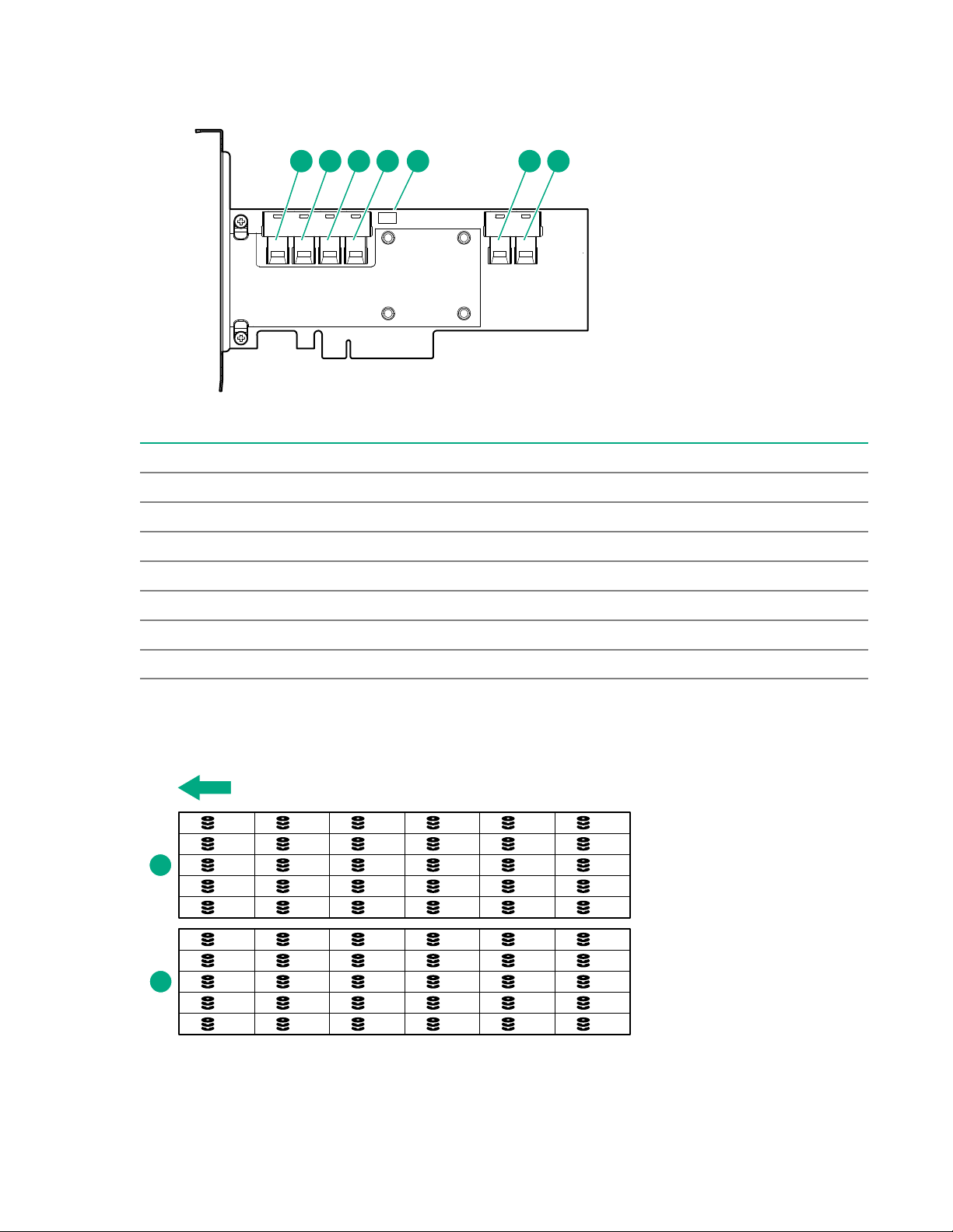
HPE Smart Array P824i-p MR Gen10 Controller port identification
1 2 3 4 65 7
1
2
3
4
5
6
7
8
9
10
11
12
13
14
15
16
17
18
19
20
21
22
23
24
25
26
27
28
29
30
1
31
32
33
34
35
36
37
38
39
40
41
42
43
44
45
46
47
48
49
50
51
52
53
54
55
56
57
58
59
60
2
Item Description
1 Internal SAS port 1i
2 Internal SAS port 2i
3 Internal SAS port 3i
4 Internal SAS port 4i
5 Energy pack connector
6 Internal SAS port 5i
7 Internal SAS port 6i
LFF drive bay numbering
The arrow indicates the front of the chassis.
18 Identifying components and LEDs
Page 19
Item Description
1
2
1 Drive drawer 1
2 Drive drawer 2
Low profile LFF drive LED definitions
Item LED Status Definition
1 Fault
\Locate
2 Online
\Activity
Solid amber The drive has failed.
Solid blue The drive is operating normally and being identified by a
management application.
Flashing amber/blue
(1 flash per second)
Flashing amber
(1 flash per second)
Solid green The drive is online and has no activity.
Flashing green
(4 flashes per second)
Flashing green
(1 flash per second)
The drive has failed, or a predictive failure alert has been
received for this drive; it also has been identified by a
management application.
A predictive failure alert has been received for this drive.
Replace the drive as soon as possible.
The drive is operating normally and has activity.
The drive is doing one of the following:
• Rebuilding
• Performing a RAID migration
• Performing a strip size migration
• Performing a capacity expansion
• Performing a logical drive extension
• Erasing
• Spare part activation
Off The drive is not configured by a RAID controller or a spare
drive.
Identifying components and LEDs 19
Page 20

Installing the chassis
1
2
Setting up and installing the chassis
Procedure
1. Set up and install the rack. For more information, see the documentation that ships with the rack.
2. Disassemble the chassis (Disassembling the chassis on page 20).
3. Install the chassis into the rack (Installing the chassis into the rack on page 26).
4. Install the system components into the chassis (Installing the system components into the chassis
on page 30).
Disassembling the chassis
Prerequisites
• Because a fully populated chassis can weigh up to 102.00 kg ( 225.00 lb), remove the pluggable
modules and system components from the chassis to make moving and installing the chassis easier.
• If you are manually lifting the chassis into the rack, be sure to have at least four people and use the
four lift handles, when lifting the chassis. The chassis lift handles are used to help move the chassis
up and on to the rails. Remove the handles when pushing the chassis into the rack. If the required
number of people, or the chassis handles are not available, use a mechanical lift.
Procedure
1. With the chassis still on the pallet, remove all components from the rear and front of the chassis:
• Power supplies
Figure 1: Removing a power supply
• Management module
20 Installing the chassis
Page 21

1
2
3
Figure 2: Removing the management module
• HPE Smart Storage Battery:
◦ Disconnect the HPE Smart Storage Battery cable.
Figure 3: Disconnecting the HPE Smart Storage Battery cable
◦ Remove the HPE Smart Storage Battery.
Installing the chassis 21
Page 22

Figure 4: Removing the HPE Smart Storage Battery
1
1
2
2
3
• I/O module
Figure 5: Removing the I/O module
• System fans.
22 Installing the chassis
Page 23

1
2
Figure 6: Removing a system fan
• Fan louver
Figure 7: Removing the fan louver
• Midplane assembly:
a. Remove the midplane assembly cover:
I. Remove the five screws on the top.
II. Remove the two screws on the sides.
Installing the chassis 23
Page 24

1
1
2
1
1
1
b. Disconnect the four drive data cables that connect to the midplane.
1
1
2
c. Disconnect the two fan cables that connect to the midplane.
d. Remove the midplane assembly:
◦ Remove the two screws on the sides of the chassis.
◦ Lift the assembly straight up.
• Server
24 Installing the chassis
Figure 8: Removing the midplane assembly
CAUTION: To avoid damage to the server, always support the bottom of the server when
removing it from the chassis.
Page 25

1
2
3
Figure 9: Removing the server from the chassis
1
2
3
CAUTION: To avoid damage to the device, do not use the removal handle to carry it.
2. Remove all LFF drives:
a. Extend the drive drawer from the chassis.
b. Remove the drives.
Installing the chassis 25
Page 26

1
2
Installing the chassis into the rack
WARNING: Always have at least four people to lift the chassis into the rack. If the chassis is being
loaded into the rack above chest level, an additional person must assist with aligning the chassis
with the rails while the other people support the weight of the chassis.
WARNING: To avoid risk of personal injury or damage to the equipment, do not stack anything on
top of rail-mounted equipment or use it as a work surface when extended from the rack.
CAUTION: Be sure to keep the product parallel to the floor when installing the chassis. Tilting the
product up or down could result in damage to the rails.
WARNING: The chassis is very heavy. To reduce the risk of personal injury or damage to the
equipment:
• Observe local occupational health and safety requirements and guidelines for manual material
handling.
• Remove all installed components from the chassis before installing or moving the chassis.
• Use caution and get help to lift and stabilize the chassis during installation or removal, especially
when the chassis is not fastened to the rack.
CAUTION: Always plan the rack installation so that the heaviest item is on the bottom of the rack.
Install the heaviest item first, and continue to populate the rack from the bottom to the top.
CAUTION: Hewlett Packard Enterprise has not tested or validated the chassis with any third-party
racks. Before installing the chassis in a third-party rack, be sure to properly scope the limitations of
the rack. Before proceeding with the installation, consider the following:
• You must fully understand the static and dynamic load carrying capacity of the rack and be sure
that it can accommodate the weight of the chassis.
• Be sure sufficient clearance exists for cabling, installation and removal of the chassis, and
actuation of the rack doors.
The chassis requires rails for installation in a rack. To install the rack rails, see the HPE Apollo 4500 4U
Rail Installation Instructions that ship with the rack hardware kit.
You can install up to nine chassis in a 36U, 1200mm deep rack. If you are installing more than one
chassis, install the first chassis in the bottom of the rack, and then install additional chassis by moving up
the rack with each subsequent chassis. Plan the rack installation carefully because it is difficult to change
the location of components after they are installed.
26 Installing the chassis
Page 27

WARNING: To reduce the risk of personal injury or damage to the equipment, be sure that:
3
1
2
4
5
• The rack is bolted to the floor using the concrete anchor kit.
• The leveling feet extend to the floor.
• The full weight of the rack rests on the leveling feet.
• The racks are coupled together in multiple rack installations.
• Only one component is extended at a time. If more than one component is extended, a rack
might become unstable.
WARNING: To reduce the risk of personal injury or equipment damage, be sure that the rack is
adequately stabilized before installing the chassis.
If you are manually lifting the chassis into the rack, be sure to use the lift handles when lifting the chassis.
The chassis lift handles are used to help move the chassis up and on to the rails. Remove the handles
when pushing the chassis into the rack.
Procedure
1. Align and install the right and left rails into the rack.
2. Align and install the support brackets on the rear of the rack.
The R and L on the brackets indicate the location when standing at the rear of the rack.
Installing the chassis 27
Page 28

1
2
3. Install a cage nut into the rack on each side in the top hole at 3U above the bottom of the rail.
1
2
4. If you are installing the chassis manually, install the chassis lift handles:
a. Align the chassis lift handles with the tick marks on the side of the chassis.
Tick marks are provided on the side of the chassis to assist with aligning the handles for
installation.
b. Install both chassis lift handles on either side of the chassis.
28 Installing the chassis
Page 29

5. Remove the chassis lift handles when sliding the chassis onto the rails:
1
2
Remove the chassis lift handles from the chassis.
Do not remove the chassis handles until the weight of the chassis is resting on the rails. Retain the
chassis handles for future use.
6. Align and install the chassis into the rack.
Slide the chassis into the rack until the ears are flush against the rack posts and secure the chassis to
the rack.
Installing the chassis 29
Page 30

1
2
3
3
Installing the system components into the chassis
1
2
Once the chassis is installed in the rack, begin installing the components in the chassis.
Installing a server
CAUTION: To prevent improper cooling and thermal damage, do not operate the server or the
enclosure unless all drive and device bays are populated with either a component or a blank.
Procedure
1. Prepare the server for installation.
2. Install the server. When seated properly, the server will be flush with the front of the chassis and the
30 Installing the chassis
release lever will close completely without resistance.
Page 31

1
2
Installing a hot-plug drive
1
2
WARNING: To reduce the risk of injury from electric shock, do not install more than one drive carrier
at a time.
Procedure
1. Remove the drive blank.
2. Prepare the low-profile LFF hot-plug drive for installation.
3. Install the LFF hot-plug drive in the chassis.
4. Determine the status of the drives using the drive LEDs on the Drive Drawer LEDs on page 10.
To configure arrays, see the HPE Smart Storage Administrator User Guide on the Hewlett Packard
Enterprise website (http://www.hpe.com/info/smartstorage/docs).
Installing the chassis 31
Page 32

Installing a flex slot power supply
WARNING: To reduce the risk of electric shock or damage to the equipment:
• Do not disable the power cord grounding plug. The grounding plug is an important safety feature.
• Plug the power cord into a grounded (earthed) electrical outlet that is easily accessible at all
times.
• Unplug the power cord from the power supply to disconnect power to the equipment.
• Do not route the power cord where it can be walked on or pinched by items placed against it.
Pay particular attention to the plug, electrical outlet, and the point where the cord extends from
the server.
Procedure
Install the component as indicated.
Installing the system fan
Procedure
Install the component as indicated.
IMPORTANT: Use the tabs to insert the system fan into the chassis. Do not push in on the system
fan grill to install it.
32 Installing the chassis
Page 33

HPE Smart Storage Battery
The HPE Smart Storage Battery supports the following devices:
• HPE Smart Storage SR controllers
• HPE Smart Storage MR controllers
• NVDIMMs
IMPORTANT: To support NVDIMMs, the HPE Smart Storage Battery must be installed.
A single 96W battery can support up to 24 devices.
After the battery is installed, it might take up to two hours to charge. Controller features requiring backup
power are not re-enabled until the battery is capable of supporting the backup power.
This server supports the 96W HPE Smart Storage Battery with the 145mm cable.
This server supports the 96W HPE Smart Storage Battery with the 260mm cable.
Installing the HPE Smart Storage Battery
NOTE: System ROM and firmware messages might display "energy pack" in place of "Smart Storage
Battery." Energy pack refers to both, HPE Smart Storage Battery and the HPE Smart Storage Hybrid
Capacitor.
Procedure
1. Remove the cable clip.
Installing the chassis 33
Page 34

2. Install the Smart Storage Battery.
3. Connect the Smart Storage Battery cable to the Smart Storage Battery connector.
34 Installing the chassis
Page 35

Installing a management module
1
2
3
Procedure
Install the component as indicated.
Installing an expansion board
Procedure
1. Remove the I/O module.
Installing the chassis 35
Page 36

1
1
2
2
3
2. Remove the support bracket from the I/O module.
2
1
3. Remove the riser assembly from the I/O module.
36 Installing the chassis
Page 37

2
2
1
1
4. Remove the PCIe blank from the expansion slot of the I/O module.
2
1
5. Install a supported expansion board option in one of the PCIe expansion slots.
Installing the chassis 37
Page 38

1
2
6. Cable the board according to the option installed. For more information, see I/O module option
cabling on page 42.
Installing an I/O module
Install any I/O module options before installing the I/O module into the chassis.
WARNING: To reduce the risk of electric shock, fire, or damage to the equipment, do not plug
telephone or telecommunications connectors into RJ-45 connectors.
Prerequisites
To install the 3x/1x I/O module, you must have ROM U40 version 1.30 or later installed.
Procedure
Install the component as indicated.
38 Installing the chassis
Page 39

1
2
2
3
3
Installing a fan louver
Procedure
Install the fan louver as indicated.
Installing the midplane assembly
Procedure
1. Install the midplane assembly in the chassis, and then secure the assembly by installing the two
screws on the sides of the chassis.
Installing the chassis 39
Page 40

2
2
1
2. Connect the four drive data cables that connect to the midplane.
2
2
1
2
2
2
3. Connect the two fan cables that connect to the midplane.
4. Install the midplane assembly cover by installing the five screws on the top and the two screws on the
sides.
40 Installing the chassis
Page 41

Cabling and powering up the chassis
Connecting the Management module to the network with the iLO ports
Procedure
If using the Management module iLO ports to connect the chassis to the network, connect all cables to
the Management module and the network.
The arrow indicates the connection to the network.
Connecting the optional HPE APM module
Procedure
1. Connect the APM to the network (orange).
2. Connect the APM to the APM ports (blue).
Cabling and powering up the chassis 41
Page 42

I/O module option cabling
HPE Smart Array E208i-p SR Gen10 Controller cabling
The HPE Apollo 4510 Gen10 Chassis supports single and dual installation for the HPE Smart Array
E208i-p SR Gen10 Controller.
Hewlett Packard Enterprise recommends installing a single controller board in slot 2. Installing a controller
board in slot 1 requires that the second processor is installed in the server.
• Single-board option
42 Cabling and powering up the chassis
Page 43

Figure 10: Mini SAS cabling with a single E208i-p board
• Dual-board option
Figure 11: Mini SAS cabling with dual E208i-p boards
HPE Smart Array P408i-p SR Gen10 Controller cabling
The HPE Apollo 4510 Gen10 Chassis supports single and dual installation for the HPE Smart Array
P408i-p SR Gen10 Controller.
Hewlett Packard Enterprise recommends installing a single controller board in slot 2. Installing a controller
board in slot 1 requires that the second processor is installed in the server.
• Single-board option
Cabling and powering up the chassis 43
Page 44

Figure 12: Mini SAS cabling with a single P408i-p board
Figure 13: Smart Storage cache backup power cabling with a single P408i-p board
• Dual-board option
44 Cabling and powering up the chassis
Page 45

Figure 14: Mini SAS cabling with dual P408i-p boards
Figure 15: Smart Storage cache backup power cabling with dual P408i-p boards
HPE Smart Array P824i-p MR Gen10 Controller cabling
The HPE Apollo 4510 Gen10 Chassis supports single and dual installation for the HPE Smart Array P824i
Gen10 Controller.
Hewlett Packard Enterprise recommends installing a single controller board in slot 2. Installing a controller
board in slot 1 requires that the second processor is installed in the server.
• Single-board option
Cabling and powering up the chassis 45
Page 46

Figure 16: SAS cabling with a single P824i-p controller
Figure 17: Smart Storage cache backup power cabling with a single P824i-p controller
• Dual-board option
46 Cabling and powering up the chassis
Page 47

Figure 18: SAS cabling with dual P824i-p controllers
Figure 19: Smart Storage cache backup power cabling with dual P824i-p controllers
Powering up the system
Procedure
1. Connect the power cables to the power supplies.
2. Connect the power cables to the power source (UPS or wall outlet) or to an installed PDU.
3. Press the Power On/Standby button on the server.
Cabling and powering up the chassis 47
Page 48

Troubleshooting
Important safety information
Familiarize yourself with the safety information in the following sections before troubleshooting the server.
Important safety information
Before servicing this product, read the Important Safety Information document provided with the server.
Symbols on equipment
The following symbols may be placed on equipment to indicate the presence of potentially hazardous
conditions.
This symbol indicates Hewlett Packard Enterprise systems and peripherals that
contain assemblies and components that are sensitive to electrostatic discharge.
Carefully observe the precautions and recommended procedures in this document to
prevent component damage from static electricity.
This symbol indicates the presence of hazardous energy circuits or electric shock
hazards. Refer all servicing to qualified personnel.
WARNING: To reduce the risk of injury from electric shock hazards, do not open this
enclosure. Refer all maintenance, upgrades, and servicing to qualified personnel.
102.00 kg
225.00 lb
This symbol indicates the presence of electric shock hazards. The area contains no
user or field serviceable parts. Do not open for any reason.
WARNING: To reduce the risk of injury from electric shock hazards, do not open this
enclosure.
This symbol on an RJ-45 receptacle indicates a network interface connection.
WARNING: To reduce the risk of electric shock, fire, or damage to the equipment, do
not plug telephone or telecommunications connectors into this receptacle.
This symbol indicates the presence of a hot surface or hot component. If this surface is
contacted, the potential for injury exists.
WARNING: To reduce the risk of injury from a hot component, allow the surface to cool
before touching.
This symbol indicates that the component exceeds the recommended weight for one
individual to handle safely.
WARNING: To reduce the risk of personal injury or damage to the equipment,
observe local occupational health and safety requirements and guidelines for manual
material handling.
48 Troubleshooting
Page 49

These symbols, on power supplies or systems, indicate that the equipment is supplied
by multiple sources of power.
WARNING: To reduce the risk of injury from electric shock, remove all power cords to
disconnect power from the system completely.
Troubleshooting resources
Troubleshooting resources are available for HPE Gen10 server products in the following documents:
• Troubleshooting Guide for HPE ProLiant Gen10 servers provides procedures for resolving common
problems and comprehensive courses of action for fault isolation and identification, issue resolution,
and software maintenance.
• Error Message Guide for HPE ProLiant Gen10 servers and HPE Synergy provides a list of error
messages and information to assist with interpreting and resolving error messages.
• Integrated Management Log Messages and Troubleshooting Guide for HPE ProLiant Gen10 and HPE
Synergy provides IML messages and associated troubleshooting information to resolve critical and
cautionary IML events.
To access the troubleshooting resources, see the Hewlett Packard Enterprise Information Library (http://
www.hpe.com/info/gen10-troubleshooting).
Troubleshooting 49
Page 50

Specifications
Environmental specifications
Specification Value
Temperature range
Operating 10°C to 35°C (50°F to 95°F)
Shipping -40°C to 70°C (-40°F to 158°F)
Maximum wet bulb temperature 28°C (82.4°F)
Relative humidity (noncondensing)
Operating 10% to 90%
Nonoperating 5% to 95%
1
All temperature ratings shown are for sea level. An altitude derating of 1°C per 300 m (1.8°F per 1,000 ft) to 3,048 m
(10,000 ft) is applicable. No direct sunlight allowed.
2
Storage maximum humidity of 95% is based on a maximum temperature of 45°C (113°F). Altitude maximum for
storage corresponds to a pressure minimum of 70 kPa.
Chassis specifications
1
2
Specification Value
Height 17.58 cm (6.92 in)
Depth 92.76 cm (36.52 in)
Width 44.8 cm (17.64 in)
Weight (fully loaded) 102 kg (225 lbs)
Weight (empty) 61 kg (135 lbs)
Power supply specifications
Depending on installed options, the server is configured with one of the following power supplies:
• HPE 800W Flex Slot Platinum Hot-plug Low Halogen Power Supply on page 51
• HPE 800W Flex Slot -48VDC Hot-plug Low Halogen Power Supply on page 51
• HPE 800W Flex Slot Titanium Hot-plug Low Halogen Power Supply on page 53
• HPE 800W Flex Slot Universal Hot-plug Low Halogen Power Supply on page 53
• HPE 1600W Flex Slot Platinum Hot-plug Low Halogen Power Supply on page 54
For detailed power supply specifications, see the QuickSpecs on the Hewlett Packard Enterprise website
(http://www.hpe.com/info/proliant/powersupply).
50 Specifications
Page 51

HPE 800W Flex Slot Platinum Hot-plug Low Halogen Power Supply
Specification Value
Input requirements —
Rated input voltage
Rated input frequency
Rated input current
Maximum rated input power
BTUs per hour
Power supply output —
100 VAC to 127 VAC
200 VAC to 240 VAC
240 VDC for China only
50 Hz to 60 Hz
Not applicable to 240 VDC
9.1 A at 100 VAC
4.4 A at 200 VAC
3.6 A at 240 VDC for China only
899 W at 100 VAC
867 W at 200 VAC
864 W at 240 VDC for China only
3067 at 100 VAC
2958 at 200 VAC
2949 at 240 VAC for China only
Rated steady-state power
Maximum peak power
800 W at 100 VAC to 127 VAC input
800 W at 100 VAC to 240 VAC input
800 W at 240 VDC input for China only
800 W at 100 VAC to 127 VAC input
800 W at 100 VAC to 240 VAC input
800 W at 240 VDC input for China only
HPE 800W Flex Slot -48VDC Hot-plug Low Halogen Power Supply
Specification Value
Input requirements —
Rated input voltage
-40 VDC to -72 VDC
-48 VDC nominal input
Table Continued
Specifications 51
Page 52

Specification Value
Rated input current
Rated input power (W)
Rated input power (BTUs per hour)
Power supply output —
Rated steady-state power (W) 800 W at -40 VDC to -72 VDC
Maximum peak power (W) 800 W at -40 VDC to -72 VDC
Maximum peak power
WARNING: To reduce the risk of electric shock or energy hazards:
22.1 A at -40 VDC input
18.2 A at -48 VDC input, nominal input
12.0 A at -72 VDC input
874 W at -40 VDC input
865 W at -48 VDC input, nominal input
854 W at -72 VDC input
2983 at -40 VDC input
2951 at -48 VDC input, nominal input
2912 at -72 VDC input
800 W at -40 VDC to -72 VDC input
• This equipment must be installed by trained service personnel.
• Connect the equipment to a reliably grounded secondary circuit source. A secondary circuit has
no direct connection to a primary circuit and derives its power from a transformer, converter, or
equivalent isolation device.
• The branch circuit overcurrent protection must be rated 27 A.
CAUTION: This equipment is designed to permit the connection of the earthed conductor of the DC
supply circuit to the earthing conductor at the equipment.
If this connection is made, all of the following must be met:
• This equipment must be connected directly to the DC supply system earthing electrode
conductor or to a bonding jumper from an earthing terminal bar or bus to which the DC supply
system earthing electrode conductor is connected.
• This equipment must be located in the same immediate area (such as adjacent cabinets) as any
other equipment that has a connection between the earthed conductor of the same DC supply
circuit and the earthing conductor, and also the point of earthing of the DC system. The DC
system must be earthed elsewhere.
• The DC supply source is to be located within the same premises as the equipment.
• Switching or disconnecting devices must not be in the earthed circuit conductor between the DC
source and the point of connection of the earthing electrode conductor.
52 Specifications
Page 53

HPE 800W Flex Slot Titanium Hot-plug Low Halogen Power Supply
Specification Value
Input requirements —
Rated input voltage
Rated input frequency
Rated input current
Maximum rated input power
BTUs per hour
Power supply output —
Rated steady-state power
200 VAC to 240 VAC
240 VDC for China only
50 Hz to 60 Hz
Not applicable to 240 VDC
4.35 A at 200 VAC 3.62 A at 240 VAC
3.62 A at 240 VDC for China only
851 W at 200 VAC
848 W at 240 VAC
848 W at 240 VDC for China only
2905 at 200 VAC
2893 at 240 VAC
2893 at 240 VDC for China only
800 W at 200 VAC to 240 VAC input
800 W at 240 VDC input for China only
Maximum peak power
800 W at 200 VAC to 240 VAC input
800 W at 240 VDC input for China only
HPE 800W Flex Slot Universal Hot-plug Low Halogen Power Supply
Specification Value
Input requirements —
Rated input voltage
Rated input frequency 50 Hz to 60 Hz
Rated input current
200 VAC to 277 VAC
380 VDC
4.4 A at 200 VAC
3.1 A at 277 VAC
2.3 A at 380 VDC
Table Continued
Specifications 53
Page 54

Specification Value
Maximum rated input power
BTUs per hour
Power supply output —
Rated steady-state power
Maximum peak power
869 W at 200 VAC
865 W at 230 VAC
861 W at 277 VAC
863 W at 380 VDC
2964 at 200 VAC
2951 at 230 VAC
2936 at 277 VAC
2943 at 380 VDC
800 W at 200 VAC to 277 VAC input
800 W at 200 VAC to 277 VAC input
HPE 1600W Flex Slot Platinum Hot-plug Low Halogen Power Supply
Specification Value
Input requirements
Rated input voltage
Rated input frequency 50 Hz to 60 Hz
Rated input current
Maximum rated input power
BTUs per hour
Power supply output
Rated steady-state power
Maximum peak power
200 VAC to 240 VAC
240 VDC for China only
8.7 A at 200 VAC
7.2 A at 240 VAC
1734 W at 200 VAC
1725 W at 240 VAC
5918 at 200 VAC
5884 at 240 VAC
1600 W at 200 VAC to 240 VAC input
1600 W at 240 VDC input
2200 W for 1 ms (turbo mode) at 200 VAC to 240
VAC input
54 Specifications
Page 55

Hot-plug power supply calculations
For hot-plug power supply specifications and calculators to determine electrical and heat loading for the
server, see the Hewlett Packard Enterprise Power Advisor website (http://www.hpe.com/info/
poweradvisor/online).
Specifications 55
Page 56

Environmental considerations
Communications interference
Hewlett Packard Enterprise system compliance tests are conducted with Hewlett Packard Enterprise
supported peripheral devices and shielded cables, such as those received with the system. The system
meets interference requirements of all countries in which it is sold. These requirements provide
reasonable protection against interference with radio and television communications.
Installing and using the system in strict accordance with Hewlett Packard Enterprise instructions
minimizes the chances that the system might cause radio or television interference. However, Hewlett
Packard Enterprise does not guarantee that the system does not interfere with radio and television
reception.
Take these precautions:
• Use only shielded cables.
• Install and route the cables according to the instructions provided.
• Ensure that all cable connector screws are firmly tightened.
• Use only Hewlett Packard Enterprise supported peripheral devices.
• Before system operation, ensure that all panels and cover plates are in place and secure.
Electrostatic discharge
Preventing electrostatic discharge
To prevent damaging the system, be aware of the precautions you must follow when setting up the
system or handling parts. A discharge of static electricity from a finger or other conductor may damage
system boards or other static-sensitive devices. This type of damage may reduce the life expectancy of
the device.
Procedure
• Avoid hand contact by transporting and storing products in static-safe containers.
• Keep electrostatic-sensitive parts in their containers until they arrive at static-free workstations.
• Place parts on a grounded surface before removing them from their containers.
• Avoid touching pins, leads, or circuitry.
• Always be properly grounded when touching a static-sensitive component or assembly.
Grounding methods to prevent electrostatic discharge
Several methods are used for grounding. Use one or more of the following methods when handling or
installing electrostatic-sensitive parts:
56 Environmental considerations
Page 57

• Use a wrist strap connected by a ground cord to a grounded workstation or computer chassis. Wrist
straps are flexible straps with a minimum of 1 megohm ±10 percent resistance in the ground cords. To
provide proper ground, wear the strap snug against the skin.
• Use heel straps, toe straps, or boot straps at standing workstations. Wear the straps on both feet
when standing on conductive floors or dissipating floor mats.
• Use conductive field service tools.
• Use a portable field service kit with a folding static-dissipating work mat.
If you do not have any of the suggested equipment for proper grounding, have an authorized reseller
install the part.
For more information on static electricity or assistance with product installation, contact the Hewlett
Packard Enterprise Support Center.
Environmental considerations 57
Page 58

Websites
General websites
Hewlett Packard Enterprise Information Library
www.hpe.com/info/EIL
Subscription Service/Support Alerts
www.hpe.com/support/e-updates
Insight Remote Support
www.hpe.com/info/insightremotesupport/docs
For additional websites, see Support and other resources.
58 Websites
Page 59

Support and other resources
Accessing Hewlett Packard Enterprise Support
• For live assistance, go to the Contact Hewlett Packard Enterprise Worldwide website:
http://www.hpe.com/info/assistance
• To access documentation and support services, go to the Hewlett Packard Enterprise Support Center
website:
http://www.hpe.com/support/hpesc
Information to collect
• Technical support registration number (if applicable)
• Product name, model or version, and serial number
• Operating system name and version
• Firmware version
• Error messages
• Product-specific reports and logs
• Add-on products or components
• Third-party products or components
Accessing updates
• Some software products provide a mechanism for accessing software updates through the product
interface. Review your product documentation to identify the recommended software update method.
• To download product updates:
Hewlett Packard Enterprise Support Center
www.hpe.com/support/hpesc
Hewlett Packard Enterprise Support Center: Software downloads
www.hpe.com/support/downloads
Software Depot
www.hpe.com/support/softwaredepot
• To subscribe to eNewsletters and alerts:
www.hpe.com/support/e-updates
• To view and update your entitlements, and to link your contracts and warranties with your profile, go to
the Hewlett Packard Enterprise Support Center More Information on Access to Support Materials
page:
www.hpe.com/support/AccessToSupportMaterials
Support and other resources 59
Page 60

IMPORTANT: Access to some updates might require product entitlement when accessed through
the Hewlett Packard Enterprise Support Center. You must have an HPE Passport set up with
relevant entitlements.
Customer self repair
Hewlett Packard Enterprise customer self repair (CSR) programs allow you to repair your product. If a
CSR part needs to be replaced, it will be shipped directly to you so that you can install it at your
convenience. Some parts do not qualify for CSR. Your Hewlett Packard Enterprise authorized service
provider will determine whether a repair can be accomplished by CSR.
For more information about CSR, contact your local service provider or go to the CSR website:
http://www.hpe.com/support/selfrepair
Remote support
Remote support is available with supported devices as part of your warranty or contractual support
agreement. It provides intelligent event diagnosis, and automatic, secure submission of hardware event
notifications to Hewlett Packard Enterprise, which will initiate a fast and accurate resolution based on your
product's service level. Hewlett Packard Enterprise strongly recommends that you register your device for
remote support.
If your product includes additional remote support details, use search to locate that information.
Remote support and Proactive Care information
HPE Get Connected
www.hpe.com/services/getconnected
HPE Proactive Care services
www.hpe.com/services/proactivecare
HPE Proactive Care service: Supported products list
www.hpe.com/services/proactivecaresupportedproducts
HPE Proactive Care advanced service: Supported products list
www.hpe.com/services/proactivecareadvancedsupportedproducts
Proactive Care customer information
Proactive Care central
www.hpe.com/services/proactivecarecentral
Proactive Care service activation
www.hpe.com/services/proactivecarecentralgetstarted
Warranty information
To view the warranty information for your product, see the links provided below:
HPE ProLiant and IA-32 Servers and Options
www.hpe.com/support/ProLiantServers-Warranties
HPE Enterprise and Cloudline Servers
www.hpe.com/support/EnterpriseServers-Warranties
HPE Storage Products
www.hpe.com/support/Storage-Warranties
HPE Networking Products
www.hpe.com/support/Networking-Warranties
60 Support and other resources
Page 61

Regulatory information
To view the regulatory information for your product, view the Safety and Compliance Information for
Server, Storage, Power, Networking, and Rack Products, available at the Hewlett Packard Enterprise
Support Center:
www.hpe.com/support/Safety-Compliance-EnterpriseProducts
Additional regulatory information
Hewlett Packard Enterprise is committed to providing our customers with information about the chemical
substances in our products as needed to comply with legal requirements such as REACH (Regulation EC
No 1907/2006 of the European Parliament and the Council). A chemical information report for this product
can be found at:
www.hpe.com/info/reach
For Hewlett Packard Enterprise product environmental and safety information and compliance data,
including RoHS and REACH, see:
www.hpe.com/info/ecodata
For Hewlett Packard Enterprise environmental information, including company programs, product
recycling, and energy efficiency, see:
www.hpe.com/info/environment
Documentation feedback
Hewlett Packard Enterprise is committed to providing documentation that meets your needs. To help us
improve the documentation, send any errors, suggestions, or comments to Documentation Feedback
(docsfeedback@hpe.com). When submitting your feedback, include the document title, part number,
edition, and publication date located on the front cover of the document. For online help content, include
the product name, product version, help edition, and publication date located on the legal notices page.
Support and other resources 61
 Loading...