

Page 1
Aruba 203R Series Wireless Access Point
E1
E2
Installation Guide
Aruba 203R Series remote access points (AP-203R and AP-203RP) are high-performance flex-radio wireless
devices for hospitality and branch deployments.
These access points contain a dual band 802.11ac flex-radio and Ethernet ports to provide secure Wi-Fi. The
wired Ethernet ports located on the back of this access point allow users to connect directly to the device when
linked by an Ethernet cable.
IEEE 802.11a/b/g/n/ac operation as a wireless access point
IEEE 802.11a/b/g/n/ac operation as a wireless air monitor
Compatibility with IEEE 802.3 at PoE
Central management configuration
Supports PoE-in (E0 port)/PoE-out (E2 port)
Support for selected USB peripherals
Integrated Bluetooth Low Energy (BLE) radio
Package Contents
The following materials are included with this product:
203R Series access point
Snap-on back cover
AC power cable
Inform your supplier if there are any incorrect, missing, or damaged parts. If possible, retain the carton, including
the original packing materials. Use these materials to repack and return the unit to the supplier if needed.
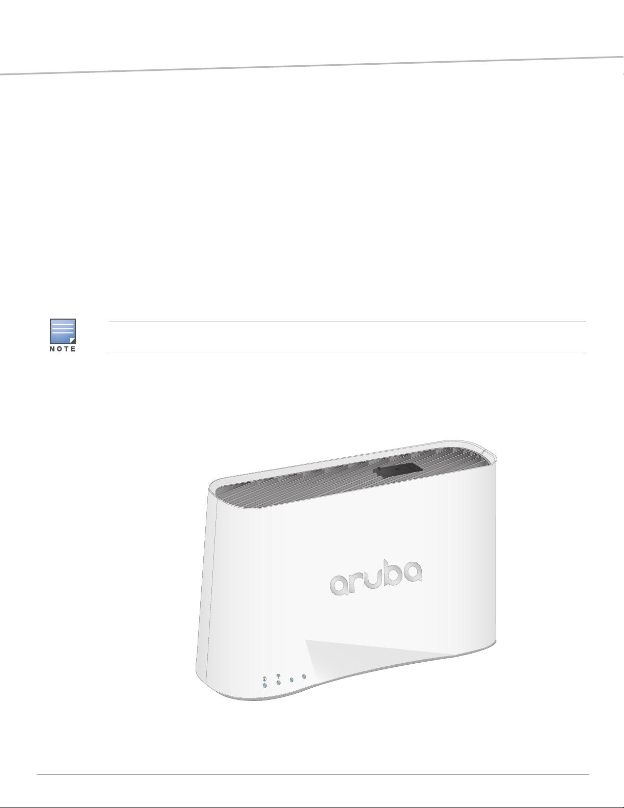
Hardware Overview
The following sections outline the hardware components of the 203R Series access point.
Figure 1 AP-303H (front view)
AP-203R-IG-01 | February 2017 1
Page 2

LED
The LED displays located on the front panel of the access point indicate the following functions:
System Status
The System Status LED indicates the operating condition of the access point, See .
Tabl e 1 System Status LEDs
Color/State Meaning
Off Device is powered off
Green/solid Device is ready; fully functional
Green/blinking
1
Device is booting; not ready
Green/flashing
2
Device is ready; uplink negotiated at suboptimal speed (<1Gbps)
Red/solid Error condition
1 blinking: 1s on/1s off
2 flashing: on/off repeated in less than 1s
Radio Status
The Radio Status LED indicates the operating mode of the access point’s radios. See Table 2.
Tabl e 2 Radio Status LEDs
Color/State Meaning
Off Meets one of the following conditions:
both radios are disabled
device is powered off
Green/solid Both radios enabled in access mode
Green/blinking1 One radio enabled in access mode; one radio disabled
Amber/solid Both radios enabled in monitor mode
Amber/flashing Device ready; operating in power-save mode, with uplink negotiated at suboptimal
Alternating
3
speed (<1Gbps)
One radio enabled in access mode; one radio in monitor mode
2 Aruba 203R Series Wireless Access Point | Installation Guide
Page 3
Network Status (E1)
E1
E2
E0
AC
The Network Status (E1) LED indicates activity transmitted to/from the wired ports. See Table 3.
Tabl e 3 Network Status LEDs
Color/State Meaning
Off Meets one of the following conditions:
the Device is powered off
port is disabled
no link/activity detected
Green/solid Link established
Green/blinking Activity detected across link
PoE-PSE (E2) Status
The PoE-PSE (E2) LED indicates when the access point is providing Power over Ethernet (PoE) to an external
device that is physically linked to the E2 port, as shown in Table 4 .
Tabl e 4 PoE-PSE Status LEDs
Color/State Meaning
Off Meets one of the following conditions:
device is powered off
port is disabled
no link established
Green/solid Access point supplying power to a connected device
Yellow/solid Device sourcing PoE power
Yellow/blinking Link activity detected from a connected device
LED Display Settings
The LEDs have three operating modes that can be selected in the system
management software:
Default mode: Refer to Table 1Tables 1-3
Off mode: LEDs are off
Blink mode: LEDs blink green
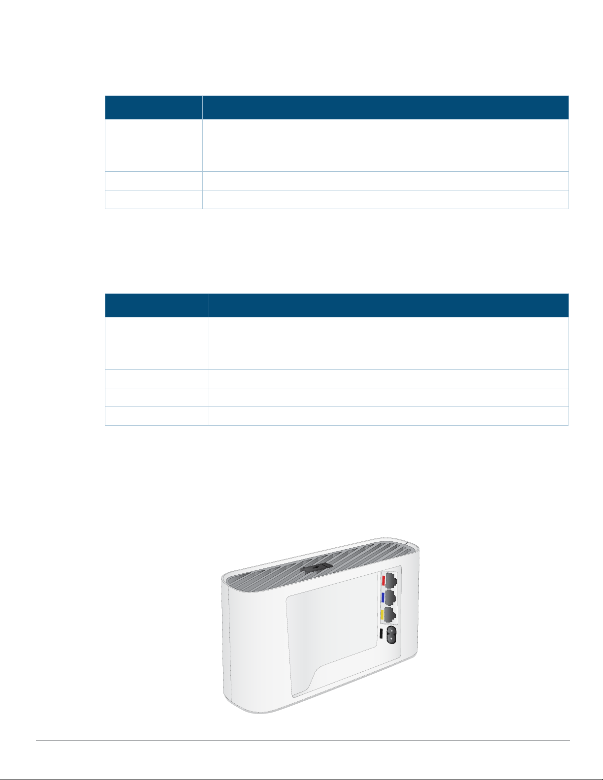
Figure 2 AP-303H (rear view)
Aruba 203R Series Wireless Access Point | Installation Guide 3
Page 4

Console Port
1: NC
2: RX
3: TX
4: GND
5: GND
The 5-pin USB Micro-B connector located on the bottom of this device allows for direct management of the
device when connected to a laptop or serial console. For pin-out details, refer to Figure 3.
Figure 3 Console Port Pin-out
Ethernet Ports
The AP-303H access point is equipped with three active Ethernet ports (E0-E2), shown in Figure 2.
The E0 port is a 100/1000 Base-T, auto-sensing MDI/MDX, which supports uplink connectivity when linked by an
Ethernet cable.
The E1-E2 ports are 1000 Base-T auto-sensing MDI/MDX, which support downlink connectivity. These ports may
be used to provide secure network connectivity and also allows for manual configuration the device when linked
by an Ethernet cable. Refer to Figure 4 for a detailed port pin-out.
Additionally, the E2 port supports PoE-out functionality, and is capable of supplying 802.3af PoE up to 15.4W to a
powered device.
Figure 4 Gigabit Ethernet Port Pin-Out
USB Interface
The top of this access point is equipped with a USB port that is compatible with cellular modems and Bluetooth
Low Energy (BLE) dongles. When active, the USB port can supply up to 5W/1A to a connected device.
Push Button
The push button located on the bottom of the device can be used to reset the access point to factory default
settings or turn off/on the LED display.
To reset the access point to factory default settings:
1. Power off the access point.
2. Press and hold the push button using a small, narrow object, such as a paperclip.
3. Power-on the access point without releasing the push button. The system status LED will flash within 5
seconds.
4. Release the push button.
The system status LED will flash again within 15 seconds indicating that the reset is completed. The access
point will now continue to boot with the factory default settings.
To turn off/on the system status LED:
During the normal operation of the access point, press the push button using a small, narrow object, such as
a paperclip. The system status LED will be turned off/on immediately.
Power
The 203R Series access point accepts AC power up to 34W when using the cord provided. The Intelligent Power
Monitoring (IPM) feature generates power consumption reports to provide increased efficiency through
management and power-saving capabilities.
The PoE-PSE and USB settings can be enabled/disabled through the software’s WebUI and CLI.
4 Aruba 203R Series Wireless Access Point | Installation Guide
Page 5

Before You Begin
Refer to the sections below before beginning the installation process.
Pre-Installation Checklist
Before installing your 203R Series access point, be sure that you have the following:
Pre-installed wall box
Cat5E UTP cable with network access installed in the wall box
Aruba AP AC power cable
One of the following network services:
Aruba Discovery Protocol (ADP)
DNS server with an “A” record
DHCP Server with vendor-specific options
This device in compliance with governmental requirements, and is designed the so that only authorized network
administrators can change the settings. For more information about access point configuration, refer to the
ArubaOS Quick Start Guide and ArubaOS User Guide.
Identifying Specific Installation Locations
When installing this access point must be secured to an Aruba-approved mount kit. This access point should be
oriented vertically, with rubber pads facing downward to facilitate maximum antenna gain. Use the access point
placement map generated by Aruba’s RF Plan software application to determine the proper installation
location(s). Each location should be as close as possible to the center of the intended coverage area and should
be free from obstructions or obvious sources of interference. These RF absorbers/reflectors/interference
sources will impact RF propagation and should be accounted for during the planning phase and adjusted for in
RF plan.
Identifying Known RF Absorbers/Reflectors/Interference Sources
Identifying known RF absorbers, reflectors, and interference sources while in the field during the installation
phase is critical. Make sure that these sources are taken into consideration when you attach an access point to its
fixed location.
RF absorbers include:
Cement/concrete—Old concrete has high levels of water dissipation, which dries out the concrete, allowing
for potential RF propagation. New concrete has high levels of water concentration in the concrete, blocking
RF signals.
Natural Items—Fish tanks, water fountains, ponds, and trees
Brick
RF reflectors include:
Metal Objects—Metal pans between floors, rebar, fire doors, air conditioning/heating ducts, mesh windows,
blinds, chain link fences (depending on aperture size), refrigerators, racks, shelves, and filing cabinets.
Do not place an access point between two air conditioning/heating ducts. Make sure that access points are
placed below ducts to avoid RF disturbances.
RF interference sources include:
Microwave ovens and other 2.4 or 5 GHz objects (such as cordless phones)
Cordless headset such as those used in call centers or lunch rooms
Access Point Setup
The 203R Series access point is designed for easy desktop deployments and includes a snap-on cover to cover
Aruba 203R Series Wireless Access Point | Installation Guide 5
Page 6

the back panel of this device.
!
E1
E2
E0
AC
All Aruba access points should be professionally installed by an Aruba-Certified Mobility Professional (ACMP).
The installer is responsible for ensuring that grounding is available and meets applicable national and electrical
codes. Failure to properly install this product may result in physical injury and/or damage to property.
Tous les points d'accès Aruba doivent impérativement être installés par un professionnel agréé. Ce dernier doit
s'assurer que l'appareil est mis à la terre et que le circuit de mise à la terre est conforme aux codes électriques
nationaux en vigueur. Le fait de ne pas installer correctement ce produit peut entraîner des blessures
corporelles et / ou des dommages matériels.
Use the steps below to install the rear snap on cover.
1. Ensure that the power and Ethernet cable(s) are plugged into the back of the access point.
2. Align the tabs on the snap-on cover with the corresponding slot on the back of the access point, then press
the cover until it snaps into place. See Figure 5.
Figure 5 Snap on Cover
Software
For instructions on choosing operating modes and initial software configuration, refer to the Access Point
Software Quick Start Guide.
Verifying Post-Installation Connectivity
The integrated LED on the access point can be used to verify that the access point access point is receiving power
and initializing successfully (see Table 1 -4). Refer to the Access Point Software Quick Start Guide for further
details on verifying post-installation network connectivity.
Electrical and Environmental Specifications
For additional specifications on this product, please refer to the product data sheet at
www.arubanetworks.com/safety_addendum.
6 Aruba 203R Series Wireless Access Point | Installation Guide
Page 7

Electrical
!
!
Ethernet:
100/1000 Base-T auto-sensing Ethernet RJ45 interface
IEEE 802.3ab/az (1000 Base-T)
Power:
34AC power interference, support powering through an AC-to-DC power adapter (AP-AC-48V36C)
Maximum power consumption with a full PoE-PSE and USB load: 34W (DC)
If a power adapter other than the Aruba-approved adapter is used in the US or Canada, it should be NRTL listed,
without an output rated 48VDC, minimum 2A, marked “LPS” and “Class 2”, and suitable for plugging into a
standard power receptacle in the US and Canada.
Environmental
Operating:
Temperature: 0°C to +40°C (+32°F to +104°F)
Humidity: 5% to 93% non-condensing
Storage and transport:
Temperature: -40°C to +70°C (-40°F to +158°F)
Humidity: 5% to 93% non-condensing
Proper Disposal of Aruba Equipment
Dispose of Aruba products per local regulation. For the most current information about Global Environmental
Compliance and Aruba products, see our website at
www.arubanetworks.com.
Regulatory Information
The regulatory model names for the 203R Series access points are:
AP-203R: APINR203
AP-203RP: APINRP203
Changes or modifications to this unit not expressly approved by the party responsible for compliance could void
the user’s authority to operate this equipment.
Toute modification effectuée sur cet équipement sans l'autorisation expresse de la partie responsable de la
conformité est susceptible d'annuler son droit d'utilisation.
FCC
Improper termination of access points installed in the United States configured to a non-US model controller is a
violation of the FCC grant of equipment authorization. Any such willful or intentional violation may result in a
requirement by the FCC for immediate termination of operation and may be subject to forfeiture (47 CFR 1.80).
The network administrator(s) is/are responsible for ensuring that this device operates in accordance with local/
regional laws of the host domain.
RF Radiation Exposure Statement: This equipment complies with FCC RF radiation exposure limits. This
equipment should be installed and operated with a minimum distance of 10.63 inches (27cm) between the
radiator and your body for 2.4 GHz and 5 GHz operations. This transmitter must not be co-located or operating
in conjunction with any other antenna or transmitter. When operated in 5.15 to 5.25 GHz frequency range, this
device is restricted to indoor use to reduce the potential for harmful interference with co-channel Mobile
Satellite Systems.
Aruba 203R Series Wireless Access Point | Installation Guide 7
Page 8

!
Déclaration sur les limites d'exposition aux radiofréquences :cet équipement est conforme aux limites
d'exposition aux rayonnements radioélectriques spécifiées par la FCC. Il doit être installé et utilisé à une distance
minimale de 27 cm par rapport à votre corps pour les fréquences de 2,4 et 5 GHz. Cet émetteur-récepteur ne
doit pas être utilisé ou situé à proximité d'autres antennes ou émetteurs-récepteurs. En cas d'utilisation dans la
plage de fréquences de 5,15 à 5,25 GHz, cet appareil doit uniquement être utilisé en intérieur afin de réduire les
risques d'interférence avec les systèmes satellites mobiles partageant le même canal.
Canada
User manuals for licence-exempt radio apparatus shall contain the following text, or an equivalent notice that
shall be displayed in a conspicuous location, either in the user manual or on the device, or both:
This device complies with Industry Canada’s licence-exempt RSSs. Operation is subject to the following two
conditions: (1) This device may not cause interference; and(2) This device must accept any interference, including
interference that may cause undesired operation of the device.
Cet appareil numerique de la classe B respecte toutes les exigencies du Reglement sur le materiel brouilleur du
Canada.
Déclaration d’Industrie Canada
Conformément aux réglementations d’Industrie Canada, cet émetteur-récepteur radio doit être utilisé
uniquement avec une antenne dont le type et le gain maximal doivent être approuvés par Industrie Canada.
Pour réduire les interférences radio potentielles, le type d’antenne et son gain doivent être choisis de façon à ce
que la puissance isotrope rayonnée équivalente (PIRE) ne dépasse pas les valeurs nécessaires à une
communication efficace.
Ce périphérique est conforme aux règlements RSS exempts de licence d’Industrie Canada. L’utilisation de ce
périphérique est soumise aux deux conditions suivantes : (1) ce périphérique ne doit pas provoquer
d’interférences, et (2) ce périphérique doit accepter toute interférence, y compris les interférences susceptibles
de provoquer un dysfonctionnement.
Medical
1. Equipment not suitable for use in the presence of flammable mixtures.
2. Connect to only IEC 60950-1 or IEC 60601-1 3rd edition certified products and power sources. The end user is
responsible for the resulting medical system complies with the requirements of IEC 60601-1 3rd edition.
3. Wipe with a dry cloth, no additional maintenance required.
4. No serviceable parts, the unit must be sent back to the manufacturer for repair.
5. No modifications are allowed without Aruba approval.
EMC Class A Warning
이 기기는 업무용 환경에서 사용할 목적으로 적합성평가를 받은 기기로서 가정용 환경에서 사용하는 경우 전파간섭
의 우려가 있습니다 .
=> 사용자 안내문은 “ 업무용방송통신기자재 ’ 에만 해당된다
Taiwan
第十二條 → 經型式認證合格之低功率射頻電機,非經許可,公司、商號或使用者均不得擅自變更頻率、加大功率或變更
原設計之特性及功能。
第十四條 → 低功率射頻電機之使用不得影響飛航安全及干擾合法通信;經發現有干擾現象時,應立即停用,並改善至無
干擾時方得繼續使用。
前項合法通信,指依電信法規定作業之無線電通信。低功率射頻電機須忍受合法通信或工業、科學及醫療用電波輻射性
電機設備之干擾。
8 Aruba 203R Series Wireless Access Point | Installation Guide
Page 9

Contact Aruba
Main Site www.arubanetworks.com
Support Site http://support.arubanetworks.com
Airheads Social Forums and
Knowledge Base
North America Telephone 1-800-943-4526 (toll free)
International Telephone http://arubanetworks.com/support-services/contact-support/
Software Licensing Site http://hpe.com/networking/support
End-of-Life Information http://arubanetworks.com/support-services/end-of-life/
Security Incident Response Team
(SIRT)
http://community.arubanetworks.com/
1-408-754-1200
Site: arubanetworks.com/support-service/security-bulletins/
Email: sirt@arubanetworks.com
Copyright
© Copyright 2017 Hewlett Packard Enterprise Development LP
Open Source Code
This product includes code licensed under the GNU General Public License, the GNU Lesser General Public License, and/or
certain other open source licenses.
A complete machine-readable copy of the source code corresponding to such code is available upon request. This offer is valid
to anyone in receipt of this information and shall expire three years following the date of the final distribution of this product
version by Hewlett Packard Enterprise Company.
To obtain such source code, send a check or money order in the amount of US
$10.00 to:
Hewlett Packard Enterprise Company
Attn: General Counsel
3000 Hanover Street
Palo Alto, CA 94304
USA
Warranty
This hardware product is protected by an Aruba warranty. For more details visit www.hpe.com/us/en/support.html
Aruba 203R Series Wireless Access Point | Installation Guide 9
 Loading...