

Page 1
DATA SHEET
The aordable mid-range Aruba 303 Series
campus access point delivers high performance
802.11ac with MU-MIMO (Wave 2) for medium
density enterprise environments. With the
integrated BLE and supporting 802.3af power,
the Aruba 303 Series AP enables enterprises to
improve their work eciency and productivity with
the lowest TCO.
The compact Aruba 303 Series AP delivers a maximum
concurrent data rate of 867 Mbps in the 5GHz band and
300 Mbps in the 2.4GHz band (for an aggregate peak
data rate of 1.2Gbps). Featuring 2x2:2SS, the Aruba 303 is
designed for medium device density environments, such as
schools, retail branches, warehouses, hotels and enterprise
oces, where the environment is cost sensitive.
The 303 Series AP has an integrated Bluetooth Low-Energy
(BLE) radio, which can be used as an Aruba beacon for
advanced locationing, indoor waynding, asset tracking,
and to enable proximity-based push notication services.
The integrated beacon radio also enables the remote
management of battery-powered and other standalone
beacons in a large-scale network of Aruba beacons. It
enables businesses to leverage mobility context to
develop applications that will deliver an enhanced user
experience and increase the value of the wireless network
for organizations.
UNIQUE BENEFITS
• Unied AP – deploy with or without controller
- The 303 Series access points can be deployed in
either controller-based (ArubaOS) or controller-less
(InstantOS) deployment mode
• Dual Radio 2x2 802.11ac access point with Multi-User
MIMO (wave 2)
- Supports up to 867Mbps in the 5GHz band (with 2SS/
VHT80 client devices) and up to 300Mbps in the 2.4GHz
band (with 2SS/HT40 clients)
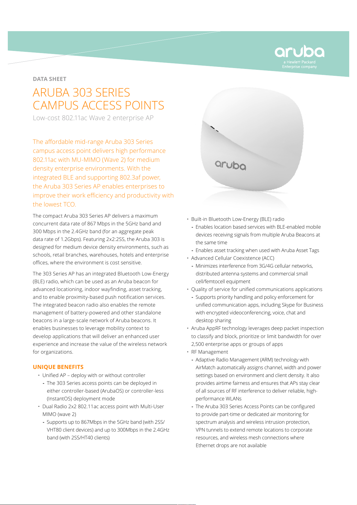
ARUBA 303 SERIES
CAMPUS ACCESS POINTS
Low-cost 802.11ac Wave 2 enterprise AP
• Built-in Bluetooth Low-Energy (BLE) radio
- Enables location based services with BLE-enabled mobile
devices receiving signals from multiple Aruba Beacons at
the same time
- Enables asset tracking when used with Aruba Asset Tags
• Advanced Cellular Coexistence (ACC)
- Minimizes interference from 3G/4G cellular networks,
distributed antenna systems and commercial small
cell/femtocell equipment
• Quality of service for unied communications applications
- Supports priority handling and policy enforcement for
unied communication apps, including Skype for Business
with encrypted videoconferencing, voice, chat and
desktop sharing
• Aruba AppRF technology leverages deep packet inspection
to classify and block, prioritize or limit bandwidth for over
2,500 enterprise apps or groups of apps
• RF Management
- Adaptive Radio Management (ARM) technology with
AirMatch automatically assigns channel, width and power
settings based on environment and client density. It also
provides airtime fairness and ensures that APs stay clear
of all sources of RF interference to deliver reliable, high-
performance WLANs
- The Aruba 303 Series Access Points can be congured
to provide part-time or dedicated air monitoring for
spectrum analysis and wireless intrusion protection,
VPN tunnels to extend remote locations to corporate
resources, and wireless mesh connections where
Ethernet drops are not available
Page 2
DATA SHEET
ARUBA 303 SERIES CAMPUS ACCESS POINTS
• Spectrum analysis
- Capable of part-time or dedicated air monitoring, the
spectrum analyzer remotely scans the 2.4GHz and 5GHz
radio bands to identify sources of RF interference from
HT20 through VHT80 operation
• Aruba Secure Core
- Device assurance: Use of Trusted Platform Module (TPM)
for secure storage of credentials and keys as well as
secure boot
- Integrated wireless intrusion protection oers threat
protection and mitigation, and eliminates the need for
separate RF sensors and security appliances
- IP reputation and security services identify, classify,
and block malicious les, URLs and IPs, providing
comprehensive protection against advanced
online threats
Daisy-chain your wired network to connect and power any
network device (IP camera, IOT gateway, or even a second Access
Point) to the E1 Ethernet port of the AP-303P. Simplify and cost-
reduce the installation of multiple devices by sharing switch
ports and cabling.
CHOOSE YOUR OPERATING MODE
The Aruba 303 Series Access Points oer a choice of deployment
and operating modes to meet your unique management and
deployment requirements:
• The 303 Series AP is a unied AP that supports both
controller-based and controller-less deployment modes,
providing maximum exibility.
• Controller-based mode – When deployed in conjunction
with an Aruba Mobility Controller, Aruba 303 Series
Access Points oer centralized conguration, data
encryption, policy enforcement and network services, as
well as distributed and centralized trac forwarding.
• Controller-less (Instant) mode – The controller function
is virtualized in a cluster of APs in Instant mode. As the
network grows and/or requirements change, Instant
deployments can easily migrate to controller-based mode.
• Remote AP (RAP) mode for branch deployments
• Air monitor (AM) for wireless IDS, rogue detection
and containment
• Spectrum analyzer (SA), dedicated or hybrid, for
identifying sources of RF interference
• Secure enterprise mesh portal or point
For large installations across multiple sites, the Aruba Activate
service signicantly reduces deployment time by automating
device provisioning, rmware upgrades, and inventory
management. With Aruba Activate, the APs can be factory-
shipped to any site and congure themselves when powered up.
SPECIFICATIONS
Hardware Variants
• AP-303 models: single Ethernet
• AP-303P models: second Ethernet with PoE out
Wi-Fi Radio Specications
• AP type: Indoor, dual radio, 5GHz 802.11ac 2x2 MIMO and
2.4GHz 802.11n 2x2 MIMO
• 5GHz (radio 0):
- Two spatial stream Single User (SU) MIMO for up to
867 Mbps wireless data rate to individual 2SS VHT80
client devices
- Two spatial stream Multi User (MU) MIMO for up to
867 Mbps wireless data rate to two 1SS MU-MIMO
capable client devices simultaneously
• 2.4GHz (radio 1):
- Two spatial stream Single User (SU) MIMO for up to
300 Mbps wireless data rate to individual 2SS HT40
client devices
• Support for up to 256 associated client devices per radio,
and up to 16 BSSIDs per radio
• Supported frequency bands (country-specic
restrictions apply):
- 2.400 to 2.4835GHz
- 5.150 to 5.250GHz
- 5.250 to 5.350GHz
- 5.470 to 5.725GHz
- 5.725 to 5.850GHz
• Available channels: Dependent on congured
regulatory domain
• Dynamic frequency selection (DFS) optimizes the use of
available RF spectrum
• Supported radio technologies:
- 802.11b: Direct-sequence spread-spectrum (DSSS)
- 802.11a/g/n/ac: Orthogonal frequency-division
multiplexing (OFDM)
• Supported modulation types:
- 802.11b: BPSK, QPSK, CCK
- 802.11a/g/n/ac: BPSK, QPSK, 16-QAM, 64-QAM,
256-QAM
Page 3
DATA SHEET
ARUBA 303 SERIES CAMPUS ACCESS POINTS
• Transmit power: Congurable in increments of 0.5dBm
• Maximum (aggregate, conducted total) transmit power
(limited by local regulatory requirements):
- 2.4GHz band: +21dBm (18dBm per chain)
- 5GHz band: +21dBm (18dBm per chain)
- Note: conducted transmit power levels exclude antenna
gain. For total (EIRP) transmit power, add antenna gain
• Advanced Cellular Coexistence (ACC) minimizes the impact
of interference from cellular networks
• Maximum ratio combining (MRC) for improved
receiver performance
• Cyclic delay/shift diversity (CDD/CSD) for improved
downlink RF performance
• Short guard interval for 20MHz, 40MHz and
80MHz channels
• Space-time block coding (STBC) for increased range and
improved reception
• Low-density parity check (LDPC) for high-eciency error
correction and increased throughput
• Transmit beam-forming (TxBF) for increased signal
reliability and range
• Supported data rates (Mbps):
- 802.11b: 1, 2, 5.5, 11
- 802.11a/g: 6, 9, 12, 18, 24, 36, 48, 54
- 802.11n: 6.5 to 300 (MCS0 to MCS15)
- 802.11ac: 6.5 to 867 (MCS0 to MCS9, NSS = 1 to 2)
- 802.11n high-throughput (HT) support: HT20/40
- 802.11ac very high throughput (VHT) support:
VHT20/40/80
- 802.11n/ac packet aggregation: A-MPDU, A-MSDU
Wi-Fi Antennas
• AP-303: Internal antenna models.
- Two vertically polarized dual-band downtilt omni-
directional antennas for 2x2 MIMO with peak antenna
gain of 3.3dBi (2.4GHz) and 5.9dBi (5GHz) per antenna.
- The antennas are optimized for horizontal ceiling
mounted orientation of the AP. The downtilt angle for
maximum gain is roughly 30 degrees.
- Combining the patterns of both antennas per radio, the
peak gain of the average (eective) pattern is 2.1dBi in
2.4GHz and 4.6dBi in 5GHz.
Other Interfaces
• E0: One 10/100/1000BASE-T Ethernet network
interface (RJ-45)
- Auto-sensing link speed and MDI/MDX
- 802.3az Energy Ecient Ethernet (EEE)
- PoE-PD: 48Vdc (nominal) 802.3af PoE
• DC power interface
• E1 (AP-303P models only): One 10/100/1000BASE-T
Ethernet network interface (RJ-45)
- Auto-sensing link speed and MDI/MDX
- 802.3az Energy Ecient Ethernet (EEE)
- PoE-PSE (output): 48Vdc (nominal) 802.3af/at PoE
• Bluetooth Low Energy (BLE) radio
• Visual indicators (tri-color LEDs): for System and
Radio status
- Zigbee 802.15.4 radio (AP-303P models only)
• Reset button: factory reset (during device power-up), LED
mode control (normal/o)
• Serial console interface (proprietary, µUSB physical jack)
• Kensington security slot
Power Sources and Consumption
• The AP supports direct DC power and Power over
Ethernet (PoE)
• When both power sources are available, DC power takes
priority over PoE
• Power sources are sold separately
AP-303 models:
• Direct DC source: 12Vdc nominal, +/- 5%
• DC power interface accepts 2.1/5.5-mm center-positive
circular plug with 9.5-mm length
• Power over Ethernet (PoE): 48Vdc (nominal) 802.3af
compliant source
• Maximum (worst-case) power consumption: 10.1W (PoE)
or 8.8W (DC)
• Maximum (worst-case) power consumption in idle mode:
4.2W (PoE) or 4.0W (DC)
Page 4
DATA SHEET
ARUBA 303 SERIES CAMPUS ACCESS POINTS
AP-303P models:
• Direct DC source: 48Vdc nominal, +/- 5%
• DC power interface accepts 1.35/3.5-mm center-positive
circular plug with 9.5-mm length
• Power over Ethernet (PoE-PD) on E0: 48Vdc (nominal)
802.3af/at/bt compliant source
• PoE-PSE function on E1 disabled when powered by
802.3af PoE
• Maximum (worst-case) power consumption: 11.3 (PoE) or
11.5 (DC)
• Maximum (worst-case) power consumption in idle mode:
6.8 (PoE) or 7.0 (DC)
• Power consumption numbers exclude power to support
PoE-PSE function on E1
Mounting
• The AP ships with a (black) mount clips to attach to a 9/16-
inch or 15/16-inch at T-bar drop-tile ceiling
• Several optional mount kits are available to attach the
AP to a variety of surfaces; see the Ordering Information
section below for details
Mechanical
• Dimensions and weight (unit, excluding mount accessories):
- 150mm (W) x 150mm (D) x 35mm (H) or
5.9” (W) x 5.9” (D) x 1.4” (H)
- AP-303 models: 260g or 9.2oz
- AP-303P models: 280g or 9.9oz
• Dimensions and weight (shipping):
- 190mm (W) x 180mm (D) x 60mm (H) or
7.4” (W) x 7.0” (D) x 2.4” (H)
- AP-303 models: 410g or 14.5oz
- AP-303P models: 430g or 15.2oz
Environmental
• Operating:
- Temperature: 0° C to +40° C (+32° F to +104° F)
- Humidity: 5% to 93% non-condensing
• Storage and transportation:
- Temperature: -40° C to +70° C (-40° F to +158° F)
Reliability (at +25C operating temperature)
• AP-303 models MTBF: 795khrs (91yrs)
• AP-303P models MTBF: 518khrs (59yrs)
Regulatory
• FCC/ISED
• CE Marked
• RED Directive 2014/53/EU
• EMC Directive 2014/30/EU
• Low Voltage Directive 2014/35/EU
• UL/IEC/EN 60950
• EN 60601-1-1 and EN 60601-1-2
For more country-specic regulatory information and
approvals, please see your Aruba representative.
Regulatory Model Numbers
• AP-303: APIN0303
• AP-303P: APINP303
Certications
• CB Scheme Safety, cTUVus
• UL2043 plenum rating
• Wi-Fi Alliance (WFA) certied 802.11a/b/g/n/ac
• Wi-Fi Alliance certied (WFA) 802.11ac with
Wave 2 features
• Passpoint
®
(Release 2) with ArubaOS and Instant 8.3+
WARR ANTY
• Aruba limited lifetime warranty
MINIMUM SOFT WARE VERSIONS
• AP-303 models: ArubaOS & Aruba InstantOS 8.3.0.0
• AP-303P models: ArubaOS & Aruba InstantOS 8.4.0.0
Page 5
DATA SHEET
ARUBA 303 SERIES CAMPUS ACCESS POINTS
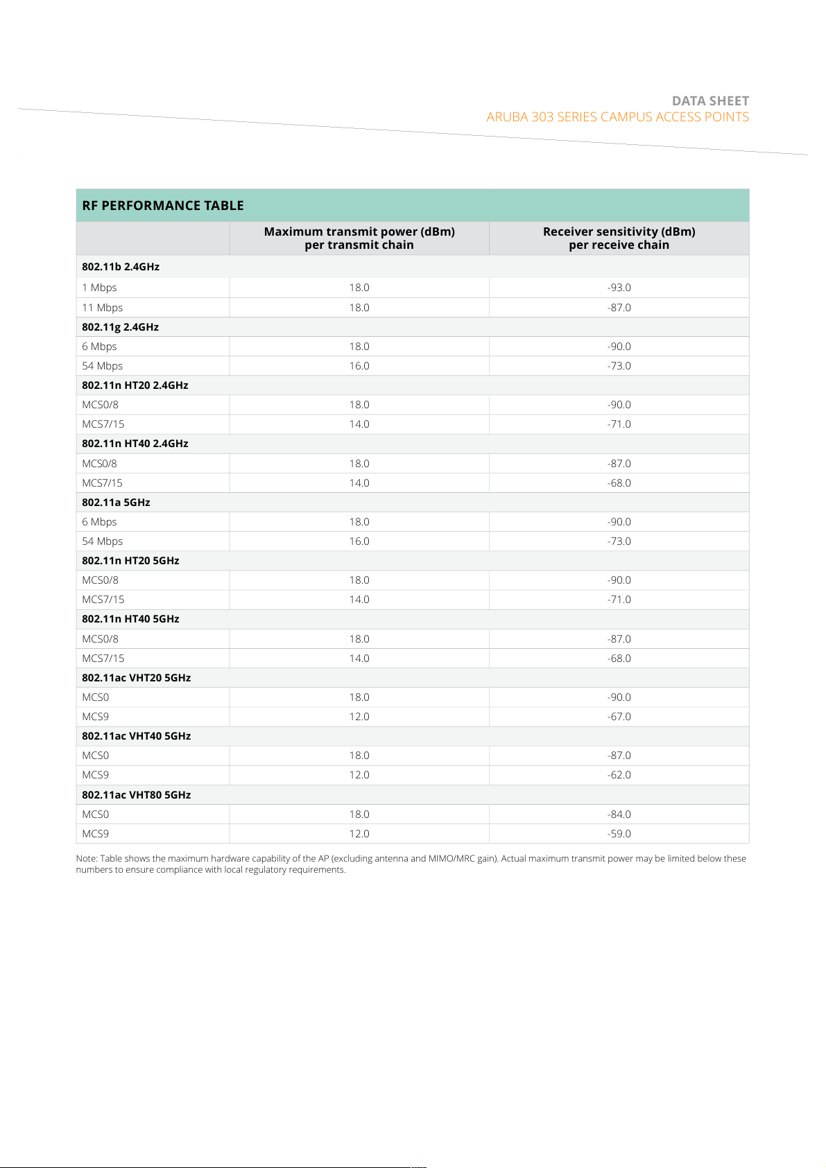
RF PERFORMANCE TABLE
Maximum transmit power (dBm)
per transmit chain
Receiver sensitivity (dBm)
per receive chain
802.11b 2.4GHz
1 Mbps 18.0 -93.0
11 Mbps 18.0 -87.0
802.11g 2.4GHz
6 Mbps 18.0 -90.0
54 Mbps 16.0 -73.0
802.11n HT20 2.4GHz
MCS0/8 18.0 -90.0
MCS7/15 14.0 -71.0
802.11n HT40 2.4GHz
MCS0/8 18.0 -87.0
MCS7/15 14.0 -68.0
802.11a 5GHz
6 Mbps 18.0 -90.0
54 Mbps 16.0 -73.0
802.11n HT20 5GHz
MCS0/8 18.0 -90.0
MCS7/15 14.0 -71.0
802.11n HT40 5GHz
MCS0/8 18.0 -87.0
MCS7/15 14.0 -68.0
802.11ac VHT20 5GHz
MCS0 18.0 -90.0
MCS9 12.0 -67.0
802.11ac VHT40 5GHz
MCS0 18.0 -87.0
MCS9 12.0 -62.0
802.11ac VHT80 5GHz
MCS0 18.0 -84.0
MCS9 12.0 -59.0
Note: Table shows the maximum hardware capability of the AP (excluding antenna and MIMO/MRC gain). Actual maximum transmit power may be limited below these
numbers to ensure compliance with local regulatory requirements.
Page 6
DATA SHEET
ARUBA 303 SERIES CAMPUS ACCESS POINTS
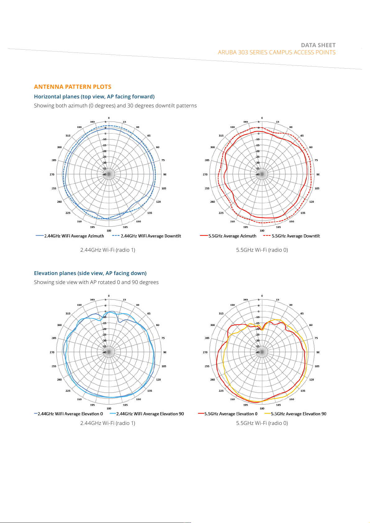
2.44GHz Wi-Fi (radio 1)
2.44GHz Wi-Fi (radio 1)
5.5GHz Wi-Fi (radio 0)
5.5GHz Wi-Fi (radio 0)
ANTENNA PATTERN PLOTS
Horizontal planes (top view, AP facing forward)
Showing both azimuth (0 degrees) and 30 degrees downtilt patterns
Elevation planes (side view, AP facing down)
Showing side view with AP rotated 0 and 90 degrees
Page 7
www.arubanetworks.com
3333 SCOTT BLVD | SANTA CLARA, CA 95054
1.844.473.2782 | T: 1.408.227.4500 | FAX: 1.408.227.4550 | INFO@ARUBANETWORKS.COM
© Copyright 2018 Hewlett Packard Enterprise Development LP. The information contained herein is subject to change without
notice. The only warranties for Hewlett Packard Enterprise products and services are set forth in the express warranty statements
accompanying such products and services. Nothing herein should be construed as constituting an additional warranty. Hewlett
Packard Enterprise shall not be liable for technical or editorial errors or omissions contained herein. DS_AP303Series_082918
DATA SHEET
ARUBA 303 SERIES CAMPUS ACCESS POINTS
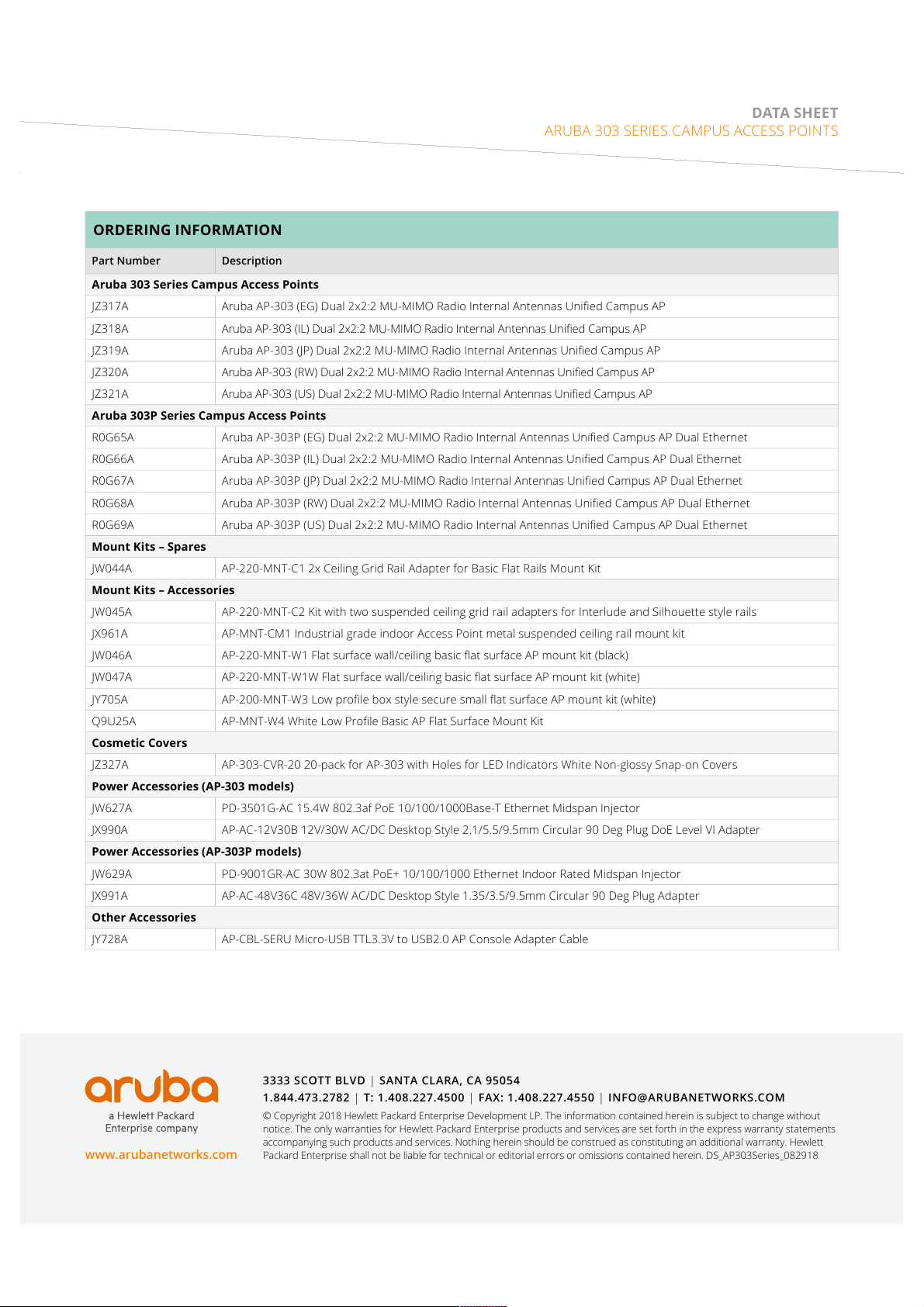
ORDERING INFORMATION
Part Number Description
Aruba 303 Series Campus Access Points
JZ317A Aruba AP-303 (EG) Dual 2x2:2 MU-MIMO Radio Internal Antennas Unied Campus AP
JZ318A Aruba AP-303 (IL) Dual 2x2:2 MU-MIMO Radio Internal Antennas Unied Campus AP
JZ319A Aruba AP-303 (JP) Dual 2x2:2 MU-MIMO Radio Internal Antennas Unied Campus AP
JZ320A Aruba AP-303 (RW) Dual 2x2:2 MU-MIMO Radio Internal Antennas Unied Campus AP
JZ321A Aruba AP-303 (US) Dual 2x2:2 MU-MIMO Radio Internal Antennas Unied Campus AP
Aruba 303P Series Campus Access Points
R0G65A Aruba AP-303P (EG) Dual 2x2:2 MU-MIMO Radio Internal Antennas Unied Campus AP Dual Ethernet
R0G66A Aruba AP-303P (IL) Dual 2x2:2 MU-MIMO Radio Internal Antennas Unied Campus AP Dual Ethernet
R0G67A Aruba AP-303P (JP) Dual 2x2:2 MU-MIMO Radio Internal Antennas Unied Campus AP Dual Ethernet
R0G68A Aruba AP-303P (RW) Dual 2x2:2 MU-MIMO Radio Internal Antennas Unied Campus AP Dual Ethernet
R0G69A Aruba AP-303P (US) Dual 2x2:2 MU-MIMO Radio Internal Antennas Unied Campus AP Dual Ethernet
Mount Kits – Spares
JW044A AP-220-MNT-C1 2x Ceiling Grid Rail Adapter for Basic Flat Rails Mount Kit
Mount Kits – Accessories
JW045A AP-220-MNT-C2 Kit with two suspended ceiling grid rail adapters for Interlude and Silhouette style rails
JX961A AP-MNT-CM1 Industrial grade indoor Access Point metal suspended ceiling rail mount kit
JW046A AP-220-MNT-W1 Flat surface wall/ceiling basic at surface AP mount kit (black)
JW047A AP-220-MNT-W1W Flat surface wall/ceiling basic at surface AP mount kit (white)
JY705A AP-200-MNT-W3 Low prole box style secure small at surface AP mount kit (white)
Q9U25A AP-MNT-W4 White Low Prole Basic AP Flat Surface Mount Kit
Cosmetic Covers
JZ327A AP-303-CVR-20 20-pack for AP-303 with Holes for LED Indicators White Non-glossy Snap-on Covers
Power Accessories (AP-303 models)
JW627A PD-3501G-AC 15.4W 802.3af PoE 10/100/1000Base-T Ethernet Midspan Injector
JX990A AP-AC-12V30B 12V/30W AC/DC Desktop Style 2.1/5.5/9.5mm Circular 90 Deg Plug DoE Level VI Adapter
Power Accessories (AP-303P models)
JW629A PD-9001GR-AC 30W 802.3at PoE+ 10/100/1000 Ethernet Indoor Rated Midspan Injector
JX991A AP-AC-48V36C 48V/36W AC/DC Desktop Style 1.35/3.5/9.5mm Circular 90 Deg Plug Adapter
Other Accessories
JY728A AP-CBL-SERU Micro-USB TTL3.3V to USB2.0 AP Console Adapter Cable
Page 8

Aruba 303P Series Campus Access Points
System Status
Radio Status
Installation Guide
The Aruba 303P Series campus access points support IEEE802.11ac Wave 2, delivering high performance with
the MU-MIMO (Multi-User Multiple-Input, Multiple-Output) technology, while also supporting 802.11a/b/g /n
wireless services. The 303P Series access points can be deployed in either a controller-based (ArubaOS) or
controller-less (InstantOS) deployment mode.
The 303P Series access points provide the following capabilities:
IEEE 802.11a/b/g/n/ac operation as a wireless access point
IEEE 802.11a/b/g/n/ac operation as a wireless air monitor
Compatibility with IEEE 802.3af PoE
Integrated Bluetooth Low Energy (BLE) radio
Package Contents
303P Series Access Point
9/16” and 15/16” combined ceiling mount adapter (Spare: AP-220-MNT-C1)
Startup guide
Inform your supplier if there are any incorrect, missing, or damaged parts. If possible, retain the carton, including
the original packing materials. Use these materials to repack and return the unit to the supplier if needed.
Hardware Overview
The following sections outline the hardware components of the 303P Series access points.
Figure 1 303P Series (front view)
Rev01 | July 2018 1
Page 9

LED
The 303P Series access points have two LEDs that indicate the system and radio status of the device. These two
LEDs can be configured via ArubaOS or Aruba Instant software into three separate modes:
Normal mode (by default): See Table 1
Both LEDs off
Blink mode: Both LEDs blink green (synchronized)
Table 1 303P Series Access Point LEDs Status in Normal Mode
LED Color/State Meaning
System Status Off Device powered off
Green- Blinking
Green- Solid Device ready for use, no restrictions
Green- Flashing
Red- Solid System error condition - immediate action required
Radio Status Off Device powered off, or both radios disabled
Green- Solid Both radios enabled in access mode
Green- Blinking One radio enabled in access mode, other disabled
1
2
Device booting, not ready for use
Device ready for use, uplink negotiated in sub optimal speed
(<1Gbps)
Amber- Solid Both radios enabled in monitor mode
Amber- Blinking One radio enabled in monitor mode, other disabled
Alternating
1 blinking: one second on, one second off, 2 seconds cycle
2 flashing: mostly on, fraction of a second off, 2 second cycle
3 alternating: one second each color, 2 second cycle
3
Green: one radio in access mode
Amber: one radio in monitor mode
2 Aruba 303P Series Campus Access Points | Installation Guide
Page 10

Figure 2 303P Series (rear view)
Console
DC Power Socket
Reset
E1E0
Kensington Lock
Slot
Aruba 303P Series Campus Access Points | Installation Guide 3
Ethernet Ports
The 303P Series access point is equipped with two 100/1000Base-T auto-sensing MDI/MDX Ethernet ports (E0
and E1) for wired network connectivity, shown in Figure 2.
The E0 port supports PoE-in (PoE-PD) functionality, allowing the 303P Series access point to be powered from an
802.3af/802.3at/802.3bt compliant PoE power supply.
The E1port supports PoE-out (PoE-PSE) functionality, capable of supplying PoE power to an external device that
is physically connected to the E1 port by Ethernet cable.
If the 303P Series access point is connected to both DC and PoE sources simultaneously, the device will draw
power from the DC source, while continuing to draw a minimal current from the PoE source. In the event that the
DC power source fails, the access point will switch to the PoE source.
For seamless failover from DC to PoE power source, the E0 port should be powered on from a PoE power source
before the DC power adapter is plugged on.
Page 11

The table below indicates the E1 port’s PSE output when the 303P Series access point is connected to DC or PoE
power supply.
Table 2 AP-303P Power Supply Matrix
Power Input on DC Jack or E0 PD
Port
48VDC PoE 802.3at DC adapter supply power only. PSE
48VDC + PoE PoE 802.3at If DC adapter and PoE (802.3af/at/
PoE 802.3af Disabled 802.3af PoE power supply only.
PoE 802.3at PoE 802.3af 802.3at PoE power supply only.
PoE 802.3bt PoE 802.3at 802.3bt PoE power supply only.
The PoE-out (PoE-PSE) functionality can be disabled (by default) or enabled on E1 port via ArubaOS or Aruba
Instant software.
Power Output on E1 PSE Port Note
output is up to 30W.
bt) supply power simultaneously,
the AP-303P will draw power from
the DC power supply. The PSE
output is up to 30W.
PSE output is disabled.
PSE output is up to 15.4W.
PSE output is up to 30W.
Power
If PoE is not available, a proprietary Aruba AP-AC-48V36C power adapter kit (sold separately) can be used to
power the 303P Series access point.
Additionally, a locally-sourced AC-to-DC adapter (or any DC source) can be used to power this device, as long as it
complies with all applicable local regulatory requirements and the DC interface meets the following
specifications:
48 Vdc (+/- 5%)
1.35/3.5 mm center-positive circular plug, 9.5 mm length
Console Port
The console port is a Micro-B connector located on the back of this device. A proprietary serial adapter cable (APCBL-SERU) is needed to use this interface. It is sold separately to connect the AP to a serial terminal or a laptop
for direct local management.
Reset Button
To reset the 303P Series access points to factory default settings, press and hold down the reset button using a
small, narrow object such as a paper clip for several seconds while powering up the AP, or for more than 10
seconds during normal operation.
To turn off/on all the LED display, press and release the reset button using a small, narrow object, such as a
paperclip for less than 10 seconds during normal operation of the access point.
Kensington Lock Slot
The 303P Series access points are equipped with a Kensington lock slot for additional security.
4 Aruba 303P Series Campus Access Points | Installation Guide
Page 12

Before You Begin
!
!
!
Refer to the sections below before beginning the installation process.
FCC Statement: Improper termination of access points installed in the United States configured to non-US
model controllers will be in violation of the FCC grant of equipment authorization. Any such willful or
intentional violation may result in a requirement by the FCC for immediate termination of operation and may
be subject to forfeiture (47 CFR 1.80).
EU Statement:
Lower power radio LAN product operating in 2.4 GHz and 5 GHz bands. Please refer to the ArubaOS/Instant
User Guide for details on restrictions.
Produit réseau local radio basse puissance operant dans la bande fréquence 2.4 GHz et 5 GHz. Merci de vous
referrer au ArubaOS/Instant User Guide pour les details des restrictions.
Low Power FunkLAN Produkt, das im 2.4 GHz und im 5 GHz Band arbeitet. Weitere Informationen bezlüglich
Einschränkungen finden Sie im ArubaOS/Instant User Guide.
Apparati Radio LAN a bassa Potenza, operanti a 2.4 GHz e 5 GHz. Fare riferimento alla ArubaOS/Instant User
Guide per avere informazioni detagliate sulle restrizioni.
Pre-Installation Checklist
Before installing the 303P Series access point, be sure that you have the following:
Cat5E or better UTP cable
One of the following power sources:
IEEE 802.3af/802.3at/802.3bt-compliant Power over Ethernet (PoE) source
Aruba AP-AC-48V36C adapter kit (sold separately)
For 303P Series access point running ArubaOS only:
Aruba controller provisioned on the network
Layer 2/3 network connectivity to your access point
One of the following network services:
Aruba Discovery Protocol (ADP)
DNS server with an “A” record
DHCP Server with vendor specific options
Aruba Networks, Inc., in compliance with governmental requirements, has designed this device so that only
authorized network administrators can change the settings. For more information about access point
configuration, refer to the ArubaOS Quick Start Guide and ArubaOS User Guide.
Access points are radio transmission devices and as such are subject to government regulations of the host
country. The network administrator(s) is/are responsible for ensuring that configuration and operation of this
equipment is in compliance with their country’s regulations. For a complete list of approved channels in your
country, refer to the Aruba Downloadable Regulatory Table at www.arubanetworks.com.
Verifying Pre-Installation Connectivity
The instructions in this section are applicable to the 303P Series access points running ArubaOS only.
Aruba 303P Series Campus Access Points | Installation Guide 5
Page 13

Before you install access points in a network environment, make sure that the access points will be able to locate
!
and connect to the controller when they are powered on. Specifically, you must verify the following conditions:
When connected to the network, each access point is assigned a valid IP address.
Access points are able to locate the controller.
Refer to the ArubaOS Quick Start Guide for instructions on locating and connecting to the controller.
Identifying Specific Installation Locations
Use the access point placement map generated by Aruba’s RF Plan software application to determine the proper
installation location(s). Each location should be as close as possible to the center of the intended coverage area
and should be free from obstructions or obvious sources of interference. These RF absorbers/reflectors/
interference sources will impact RF propagation and should be accounted for during the planning phase and
adjusted for in RF plan.
Identifying Known RF Absorbers/Reflectors/Interference Sources
Identifying known RF absorbers, reflectors, and interference sources while in the field during the installation
phase is critical. Make sure that these sources are taken into consideration when you attach an access point to its
fixed location.
RF absorbers include:
Cement/concrete—Old concrete has high levels of water dissipation, which dries out the concrete, allowing
for potential RF propagation. New concrete has high levels of water concentration in the concrete, blocking
RF signals.
Natural Items—Fish tanks, water fountains, ponds, and trees
Brick
RF reflectors include:
Metal Objects—Metal pans between floors, rebar, fire doors, air conditioning/heating ducts, mesh windows,
blinds, chain link fences (depending on aperture size), refrigerators, racks, shelves, and filing cabinets.
Do not place an access point between two air conditioning/heating ducts. Make sure that access points are
placed below ducts to avoid RF disturbances.
RF interference sources include:
Microwave ovens and other 2.4 or 5 GHz objects (such as cordless phones)
Cordless headset such as those used in call centers or lunch rooms
Installing the Access Point
The access point ships with a ceiling mount adapter to attach to a 9/16” or 15/16” ceiling rail. Additional ceiling or
wall mount kits are sold separately as accessories.
Service to all Aruba products should be performed by trained service personnel only.
The installer is responsible for securing the access point onto the ceiling tile rail in accordance with the steps
below. Failure to properly install this product may result in physical injury and/or damage to property.
1. Pull the necessary cables through a prepared hole in the ceiling tile near where the access point will be
placed.
2. Place the mount adapter against the back of the access point with the mount adapter at an angle of
approximately 30 degrees to the tabs (see Figure 3).
Twist the mount adapter clockwise until it snaps into place in the tabs (see Figure 3).
6 Aruba 303P Series Campus Access Points | Installation Guide
Page 14

Figure 3 Attaching the Ceiling Mount Adapter to the AP
3. Hold the access point next to the ceiling tile rail with the ceiling tile rail mounting slots at approximately a 30degree angle to the ceiling tile rail (see Figure 4). Make sure that any cable slack is above the ceiling tile.
4. Pushing toward the ceiling tile, rotate the access point clockwise until the device clicks into place on the
ceiling tile rail.
Aruba 303P Series Campus Access Points | Installation Guide 7
Page 15

Figure 4 Mounting the Access Point to a 15/16” ceiling rail
Figure 5 Mounting the Access Point to a 9/16” ceiling rail
Verifying Post-Installation Connectivity
The integrated LED on the access point can be used to verify that the access point access point is receiving power
and initializing successfully (see Table 1). Refer to the ArubaOS Quick Start Guide for further details on verifying
post-installation network connectivity.
Electrical and Environmental Specifications
For additional specifications on this product, please refer to the product data sheet at www.arubanetworks.com.
Electrical
Ethernet:
2 x 100/1000 Base-T auto-sensing Ethernet interface (RJ-45)
8 Aruba 303P Series Campus Access Points | Installation Guide
Page 16

Power:
!
!
!
!
!
Direct DC source: 48Vdc nominal, +/- 5%
Power over Ethernet (PoE): 802.3af/802.3at/802.3bt compliant source
Connect only to IEC 60950-1 or IEC 60601-1 products and power sources.
If a power adapter other than the Aruba-approved adapter is used in the US or Canada, it should be NRTL
listed, with an output rated 48Vdc, minimum 1A, marked “LPS” and “Class 2”, and suitable for plugging into a
standard power receptacle in the US and Canada.
Environmental
Operating:
Temperature: 0°C to +40°C (+32°F to +104°F)
Humidity: 5% to 93% non-condensing
Storage and transport
Temperature: -40°C to +70°C (-40°F to +158°F)
The Aruba 303P Series access points are for indoor use only. The access point, AC adapter, and all connected
cables are not designed for outdoor use.
Regulatory Information
The following regulatory model names apply to the 303P Series access points:
AP-303P: APINP303
FCC
To view the FCC ID for controller-managed access points:
1. Log into the controller WebUI
2. Navigate to Maintenance > Controller > About
To view the FCC ID for Instant access points:
1. Log into the virtual controller WebUI
2. Navigate to Maintenance > About
RF Radiation Exposure Statement: This equipment complies with RF radiation exposure limits. This
equipment should be installed and operated with a minimum distance of 13.78 inches (35cm) between the
radiator and your body for 2.4 GHz and 5 GHz operations. This transmitter must not be co-located or operating
in conjunction with any other antenna or transmitter.
Déclaration de la concernant l’exposition aux rayonnements à fréquence radioélectrique (FR): Cet
appareil est conforme aux limites d’exposition aux rayonnements FR établies par la FCC. Il doit être installé et
utilisé à une distance minimale de 35 cm (13,78 pouces) entre le radiateur et votre corps, qu’il opère sur la
bande 2,4 GHz ou 5 GHz. Cet émetteur ne doit pas être installé ou utilisé à proximité immédiate d’une autre
antenne ni d’un autre transmetteur.
Changes or modifications to this unit not expressly approved by the party responsible for compliance could
void the user’s authority to operate this equipment.
Toute modification effectuée sur cet équipement sans l'autorisation expresse de la partie responsable de la
conformité est susceptible d'annuler son droit d'utilisation.
Aruba 303P Series Campus Access Points | Installation Guide 9
Page 17

Federal Communication Commission
This device complies with Part 15 of the FCC Rules. Operation is subject to the following two conditions: (1)this
device may not cause harmful interference, and (2) this device must accept any interference received, including
interference that may cause undesired operation.
This equipment has been tested and found to comply with the limits for a Class B digital device, pursuant to Part
15 of the FCC Rules. These limits are designed to provide reasonable protection against harmful interference in a
residential installation. This equipment generates, uses and can radiate radio frequency energy and, if not
installed and used in accordance with the manufacturer’s instructions, may cause harmful interference to radio
communications. However, there is no guarantee that interference will not occur in a particular installation. If
this equipment does cause harmful interference to radio or television reception, which can be determined by
turning the equipment off and on, the user is encouraged to try to correct the interference by one or more of the
following measures:
Reorient or relocate the receiving antenna.
Increase the separation between the equipment and receiver.
Connect the equipment to an outlet on a circuit different from that to which the receiver is connected.
Consult the dealer or an experienced radio or TV technician for help.
Industry Canada
This Class B digital apparatus meets all of the requirements of the Canadian Interference-Causing Equipment
Regulations.
In accordance with Industry Canada regulations, this radio transmitter and receiver may only be used with an
antenna, the maximum type and gain of which must be approved by Industry Canada. To reduce potential radio
interference, the type of antenna and its gain shall be chosen so that the equivalent isotropic radiated power
(EIRP) does not exceed the values necessary for effective communication.
This device complies with Industry Canada's license-exempt RSS regulations. Operation of this device is subject
to the following two conditions: (1) this device may not cause interference, and (2) this device must accept any
interference, including interference that may cause undesired operation.
When operated in the 5.15 to 5.25 GHz frequency range, this device is restricted to indoor use to reduce the
potential for harmful interference with co-channel Mobile Satellite Systems.
Déclaration d’Industrie Canada
Conformément aux réglementations d’Industrie Canada, cet émetteur-récepteur radio doit être utilisé
uniquement avec une antenne dont le type et le gain maximal doivent être approuvés par Industrie Canada.
Pour réduire les interférences radio potentielles, le type d’antenne et son gain doivent être choisis de façon à ce
que la puissance isotrope rayonnée équivalente (PIRE) ne dépasse pas les valeurs nécessaires à une
communication efficace.
Ce périphérique est conforme aux règlements RSS exempts de licence d’Industrie Canada. L’utilisation de ce
périphérique est soumise aux deux conditions suivantes : (1) ce périphérique ne doit pas provoquer
d’interférences, et (2) ce périphérique doit accepter toute interférence, y compris les interférences susceptibles
de provoquer un dysfonctionnement.
En cas d'utilisation dans la plage de fréquences de 5,15 à 5,25 GHz, cet appareil doit uniquement être utilisé en
intérieur afin de réduire les risques d'interférence avec les systèmes satellites mobiles partageant le même
canal.
EU Regulatory Conformance
The Declaration of Conformity made under Radio Equipment Directive 2014/53/EU is available for
viewing at: www.hpe.com/eu/certificates. Select the document that corresponds to your device’s model number
as it is indicated on the product label.
Wireless Channel Restrictions
5150-5350MHz band is limited to indoor only in the following countries; Austria (AT), Belgium (BE), Bulgaria (BG),
Croatia (HR), Cyprus (CY), Czech Republic (CZ), Denmark (DK), Estonia (EE), Finland (FI), France (FR), Germany (DE),
Greece (GR), Hungary (HU), Iceland (IS), Ireland (IE), Italy (IT), Latvia (LV), Liechtenstein (LI), Lithuania (LT),
Luxembourg (LU), Malta (MT), Netherlands (NL), Norway (NO), Poland (PL), Portugal (PT), Romania (RO), Slovakia
(SK), Slovenia (SL), Spain (ES), Sweden (SE), Switzerland (CH), Turkey (TR), United Kingdom (UK)
.
Frequency Range MHz Max EIRP
2402-2480 9 dbm
10 Aruba 303P Series Campus Access Points | Installation Guide
Page 18

Frequency Range MHz Max EIRP
!
!
!
!
2412-2472 20 dbm
5150-5250 23 dbm
5250-5350 23 dbm
5470-5725 30 dbm
5725-5850 N/A for EU
Lower power radio LAN product operating in 2.4 GHz and 5 GHz bands. Please refer to the ArubaOS User Guide/
Instant User Guide for details on restrictions.
Medical
1. Equipment not suitable for use in the presence of flammable mixtures.
2. Connect to only IEC 60950-1 or IEC 60601-1 certified products and power sources. The end user is
responsible for the resulting medical system complies with the requirements of IEC 60601-1.
3. Wipe with a dry cloth, no additional maintenance required.
4. No serviceable parts, the unit must be sent back to the manufacturer for repair.
5. No modifications are allowed without Aruba approval.
This device is intended for indoor use, in hallways, breakrooms, office areas of professional medical facilities.
This device should not be installed in rooms housing patients.
This device has no IEC/EN60601-1-2 essential performance.
Use of this equipment adjacent to or stacked with other equipment should be avoided because it could result
in improper operation. If such use is necessary, this equipment and the other equipment should be observed
to verify that they are operating normally.
Compliance is based on the use of Aruba approved accessories. Refer to the ordering guide for this access
point at http://www.arubanetworks.com/assets/og/OG_AP-510Series.pdf.
Use of accessories, transducers and cables other than those specified or provided by the manufacturer of this
equipment could result in increased electromagnetic emissions or decreased electromagnetic immunity of this
equipment and result in improper operation.
Portable RF communications equipment (including peripherals such as antenna cables and external antennas)
should be used no closer than 30 cm (12 inches) to any part of the access point. Otherwise, degradation of the
performance of this equipment could result.
Brazil
Este equipamento não tem direito à proteção contra interferência prejudicial e não pode causar interferência
em sistemas devidamente autorizados.
Aruba 303P Series Campus Access Points | Installation Guide 11
Page 19

Japan
México
La operación de este equipo está sujeta a las siguientes dos condiciones: (1) es posible que este equipo o
dispositivo no cause interferencia perjudicial y (2) este equipo o dispositivo debeaceptar cualquier interferencia,
incluyendo la que pueda causar su operación no deseada.
Morocco
Нормативные требования Евразийского Экономического Союза
HPE Russia: ООО "Хьюлетт Паккард Энтерпрайз" Российская Федерация, 125171, г.
Москва, Ленинградское шоссе, 16А, стр.3, Телефон : +7 499 403 4248 Факс: +7 499 403
4677
'HPE Belarus': ИООО «Хьюлетт-Паккард Бел», Республика Беларусь, 220030, г. Минск,
ул. Интернациональная, 36-1, Теле фон/факс: +375 17 392 28 20
'HPE Kazakhstan': TOO «Хьюлетт-Паккард (К)», Республика Казахстан, 050040, г.
Алматы, Бостандыкский район, проспект Аль-Фараби, 77/7, Те лефон/факс: + 7 727 355 35 50
Kazakhstan
ЖШС "Хьюлетт Паккард Энтерпрайз" Ресей Федерациясы, 125171, Мәскеу, Ленинград тас жолы, 16A блок
3, Телефо н: +7 499 403 4248 Факс: +7 499 403 4677
«HEWLETT-PACKARD Bel» ЖШС, Беларусь Республикасы, 220030, Минск қ., Интернациональная көшесі, 36/
1, Телефо н/факс: +375 17 392 28 20
ЖШС «Хьюлетт-Паккард (К)», Қазақстан Республикасы, 050040, Алматы к., Бостандык ауданы, Әл-Фараби
даңғ ылы, 77/7, Телефон/факс: +7 (727) 355 35 50
Taiwan
第十二條
經型式認證合格之低功率射頻電機,非經許可,公司、商號或使用者均不得擅自變更頻率、加大功率或變更原設計
之特性及功能。
第十四條
低功率射頻電機之使用不得影響飛航安全及干擾合法通信;經發現有干擾現象時,應立即停用,並改善至無干擾時
方得繼續使用。
前項合法通信,指依電信法規定作業之無線電通信。
低功率射頻電機須忍受合法通信或工業、科學及醫療用電波輻射性電 機設備之干擾。
Proper Disposal of Aruba Equipment
Dispose of Aruba products per local regulation. For the most current information about Global Environmental
Compliance and Aruba products, see our website at www.arubanetworks.com.
12 Aruba 303P Series Campus Access Points | Installation Guide
Page 20

Waste of Electrical and Electronic Equipment
Aruba products at end of life are subject to separate collection and treatment in the EU
Member States, Norway, and Switzerland and therefore are marked with the symbol shown at
the left (crossed-out wheelie bin). The treatment applied at end of life of these products in
these countries shall comply with the applicable national laws of countries implementing
Directive 2012/19/EU of the European Parliament and of the Council on Waste Electrical and
Electronic Equipment (WEEE).
European Union RoHS
Aruba products also comply with the EU Restriction of Hazardous Substances Directive
2011/65/EC (RoHS). EU RoHS restricts the use of specific hazardous materials in the
manufacture of electrical and electronic equipment. Specifically, restricted materials
under the RoHS Directive are Lead (including Solder used in printed circuit assemblies),
Cadmium, Mercury, Hexavalent Chromium, and Bromine. Some Aruba products are subject to the exemptions
listed in RoHS Directive Annex 7 (Lead in solder used in printed circuit assemblies). Products and packaging will
be marked with the “RoHS” label shown at the left indicating conformance to this directive.
China RoHS
Aruba products also comply with China environmental declaration requirements and are labeled with the “EFUP
25” label shown below.
Aruba 303P Series Campus Access Points | Installation Guide 13
Page 21

Taiwan RoHS
單元
限用物質及其化學符號
台灣限用物質含有情況標示
鉛 (Pb) 汞 (Hg)
六價壗
夃 (Cd)
多䘳聯䴙
(
&U
)
(PBB)
多䘳二䴙
(PBDE)
傳輸線和線材
〇〇 〇 〇 〇 〇
外殼
−
〇〇〇 〇 〇
記憶體
〇〇 〇 〇 〇 〇
−
〇
其他機械組裝設備
〇〇 〇 〇
−
〇〇〇 〇 〇
印刷電路零組件 (PCAs)
(斷路器 選配)
−
〇〇〇 〇 〇
(冷卻及加熱系統 選配)
〇〇 〇 〇 〇 〇
(風扇 選配)
〇〇 〇 〇 〇 〇
()
−
存取裝置(HDD) 選配
〇〇〇 〇 〇
−
〇〇〇 〇 〇
讀寫元件(CD/DVD/ 磁䜮
機)(選配)
() −
〇
變壓器/電源供應器 選配
〇〇 〇 〇
備考1.〝〇係指該項限用物質之百分比含量未超出百分比含量基準。
備考2.〝−係指該項限用物質為排除項目。
選配單元使用於特定產品型號,詳細規格請參照產品說明書。
India RoHS
This product complies with RoHS requirements as prescribed by E-Waste (Management & Handling) Rules,
governed by the Ministry of Environment & Forests, Government of India.
Turkey RoHS
Ukraine RoHS
14 Aruba 303P Series Campus Access Points | Installation Guide
Page 22

Contacting Support
Table 3 Contact Information
Main Site www.arubanetworks.com
Support Site https://support.arubanetworks.com
Airheads Social Forums and Knowledge
Base
North American Telephone 1-800-943-4526 (Toll Free)
International Telephones http://www.arubanetworks.com/support-services/contact-support/
Software Licensing Site https://hpe.com/networking/support
End of Support information http://www.arubanetworks.com/support-services/end-of-life-
Security Incident Response Team (SIRT) Site: http://www.arubanetworks.com/support-services/security-
community.arubanetworks.com
1-408-754-1200
products/end-of-life-policy/
bulletins/
Email: sirt@arubanetworks.com
Copyright
© Copyright 2018 Hewlett Packard Enterprise Development LP
Open Source Code
This product includes code licensed under the GNU General Public License, the GNU Lesser General Public
License, and/or certain other open source licenses. A complete machine-readable copy of the source code
corresponding to such code is available upon request. This offer is valid to anyone in receipt of this information
and shall expire three years following the date of the final distribution of this product version by Hewlett Packard
Enterprise Company. To obtain such source code, send a check or money order in the amount of US $10.00 to:
Hewlett Packard Enterprise Company
Attn: General Counsel
3000 Hanover Street
Palo Alto, CA 94304
USA
Warranty
This hardware product is protected by an Aruba warranty. For more details visit www.hpe.com/us/en/
support.html
Aruba 303P Series Campus Access Points | Installation Guide 15
 Loading...