

Aruba 340 Series Access Points
Installation Guide
Aruba 340 Series access points (AP-344 and AP-345) are high-performance dual-radio wireless
devices. These access points use Multi-User Multiple-Input, Multiple-Output (MU-MIMO) technology
to provide secure wireless connectivity for both 2.4GHz 802.11 b/g/n and 5GHz 802.11a/n/ac Wi-Fi
networks. The optional dual-5GHz radio mode allows both radios to operate in the 5GHz radio mode
simultaneously, delivering true dual-5GHz performance. The 340 Series can be deployed in both
controller-based or controllerless network environments.
The two wired Ethernet ports located on the back of this access point allow users to connect directly
to the device when linked by an Ethernet cable. The 340 Series can be attached to a 9/16" or 15/16”
ceiling rail using the provided mount adapters.
The Aruba 340 Series provides the following capabilities:
IEEE 802.11a/b/g/n/ac operation as a wireless access point
IEEE 802.11a/b/g/n/ac operation as a wireless Air Monitor
IEEE 802.11a/b/g/n/ac operation as a Spectrum Analysis
Supports IEEE 802.3az (Energy Efficient Ethernet)
Compatible with IEEE 802.3at PoE+ power sources
Compatible with IEEE 802.3at PoE power sources
Supports selected USB peripherals
Integrated Bluetooth Low Energy (BLE) radio
Package Contents
The following materials are included with this product:
Aruba 340 Series access point
9/16" and 15/16” ceiling rail adapters
Declaration of Conformity document
End-User License Agreement document
Aruba 340 Series Access Point Startup Guide
Inform your supplier if there are any incorrect, missing, or damaged parts. If possible, retain the carton, including
the original packing materials. Use these materials to repack and return the unit to the supplier if needed.
Hardware Overview
The following sections outline the hardware components of the 340 Series access point.
APIN340-IG-01 | Month Year 1
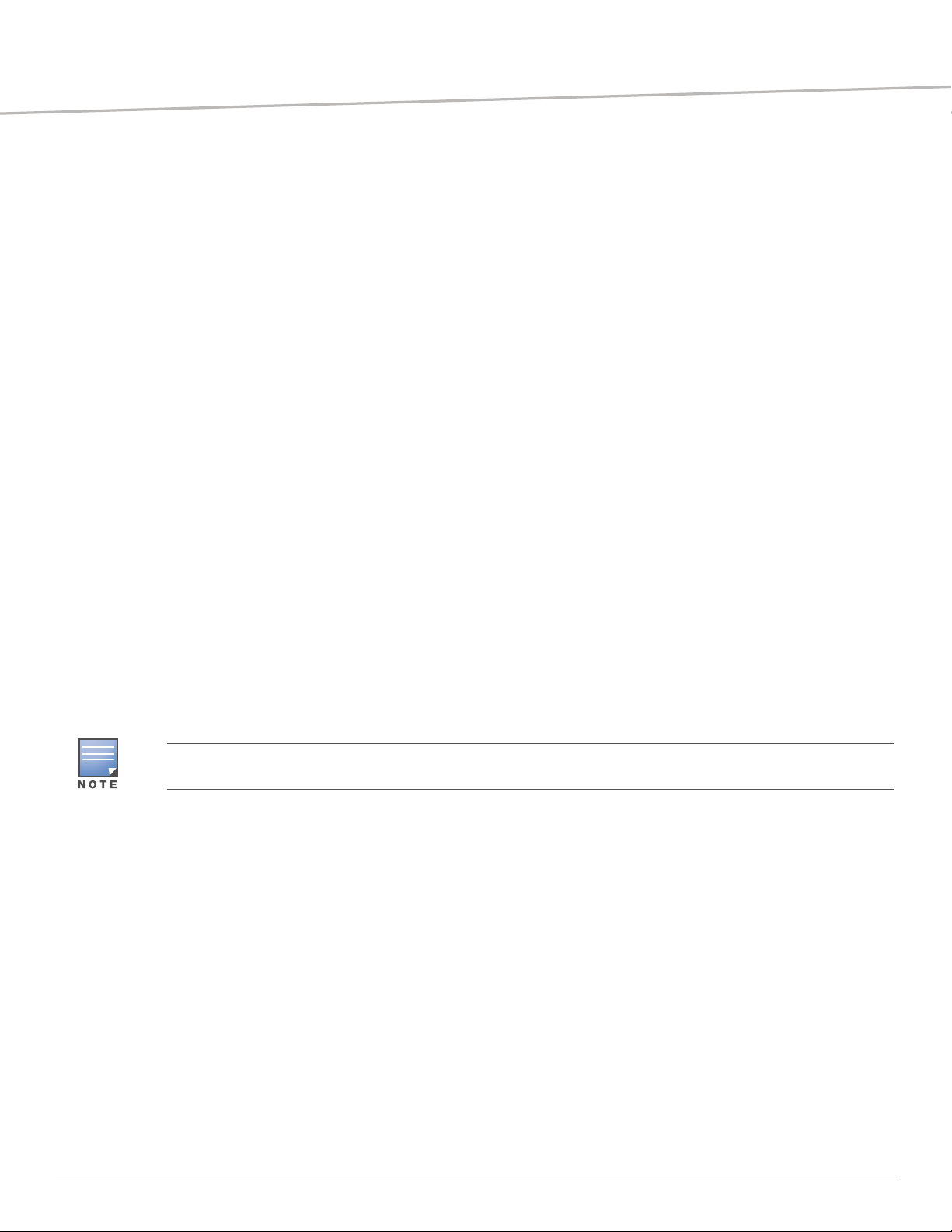
Figure 1 Aruba AP-345 (front view)
LED
The LED displays located on the front panel of the access point indicate the following functions:
System Status
The System Status LED indicates the operating condition of the access point, See Ta ble 1 .
Tabl e 1 System Status LEDs
Color/State Meaning
Off AP powered off
Green- solid Device is ready; no network restrictions
Green- blinking
Green- flashing
Amber- solid Device is ready; operating in Power Save mode due to one of the following:
Amber- flashing Device is ready; operating in Power Save mode due to one of the following
Red/solid Error condition
1
2
Device is booting; not ready
Device is ready; uplink is negotiating are at sub-optimal speed (<1Gbps)
powered by an 802.3af POE source
Intelligent Power Monitoring (IPM) mode restrictions
No network restrictions
conditions:
powered by an 802.3af POE source
Intelligent Power Monitoring (IPM) mode
Uplink is negotiating at suboptimal speed (<1Gbps)
1 Blinking: one second on/one second off.
2 Flashing: on/off repeated in less than 1s
Radio Status
The Radio Status LED indicates the operating mode of the access point’s radios. See Tab le 2.
2 Aruba 340 Series Access Points | Installation Guide
Tabl e 2 Radio Status LEDs
CONSOLE
48V 650mA
K
ENET1 ENET0
57V 600mA
USB port
DC power socket
Ethernet ports
Reset button
Kensington Lock
Console port
Color/State Meaning
Off Meets one of the following conditions:
device is powered off
both radios are disabled
Green- solid Both radios operating in access mode
Green- blinking
1
One radio operating in access mode; one radio disabled
Amber- solid Both radios operating in monitor mode
Amber- blinking One radio operating in monitor mode; one radio disabled
Green/Amber- alternating One radio operating in access mode; one radio in monitor mode
Blue- On Radios operating in dual-5GHz mode
LED Display Settings
The LEDs have three operating modes that can be selected in the system management software:
Default mode: Refer to Table 1-4
Off mode: LEDs are off
Blink mode: LEDs blink green
Figure 2 AP-344 access point (rear view)
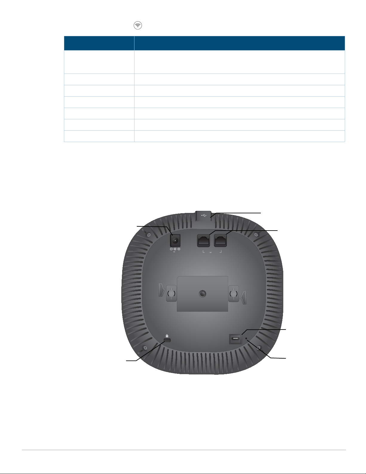
External Antenna Connectors
The AP-345 access points are equipped with four external antenna connectors located on the front
corners of the access point (see Figure 3).
Aruba 340 Series Access Points |Installation Guide 3
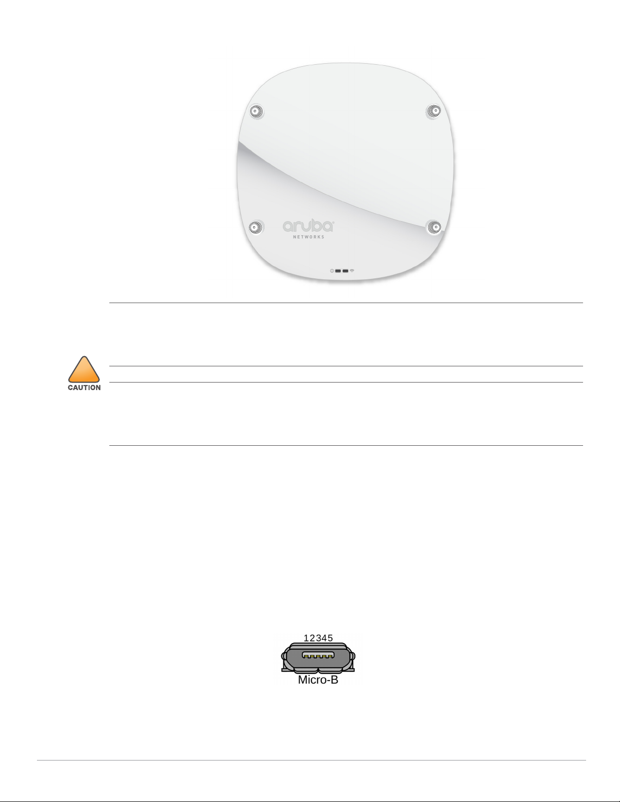
Figure 3 External Antenna Connectors
ANT0 ANT1
ANT3 ANT2
!
1: NC
2: RX
3: TX
4: GND
5: GND
External antennas for this device must be installed by an Aruba Certified Mobility Professional (ACMP) or other
Aruba-certified technician, using manufacturer-approved antennas only.
The Equivalent Isotropically Radiated Power (EIRP) levels for all external antenna devices must not exceed the
regulatory limit set by the host country/domain.
Installers are required to record the antenna gain for this device in the system management software.
Les antennes externes pour cet appareil doivent être installées par un professionnel de la mobilité certifié Aruba
(ACMP) ou un autre technicien certifié Aruba, en utilisant uniquement des antennes approuvées par le fabricant.
Les niveaux équivalents de puissance à rayonnement isotrope (EIRP) pour tous les périphériques d'antenne
externe ne doivent pas dépasser la limite réglementaire définie par le pays hôte / domaine.
Les installateurs doivent enregistrer le gain d'antenne pour cet appareil dans le logiciel de gestion du système.
Bluetooth Low Energy Radios
Aruba 340 Series access points are equipped with an integrated BLE radio that provide the following
capabilities:
location beacon applications
wireless console access
Console Port
The 5-pin Micro-B connector located on the back of this device. Use an AP-CBL-SERU cable for direct
management of this device when connected to a laptop or serial console. For pin-out details, refer to
Figure 4.
Figure 4
Micro-B Port Pin-out
Ethernet Ports
4 Aruba 340 Series Access Points | Installation Guide
Aruba 340 Series access points are equipped with two active Ethernet ports:
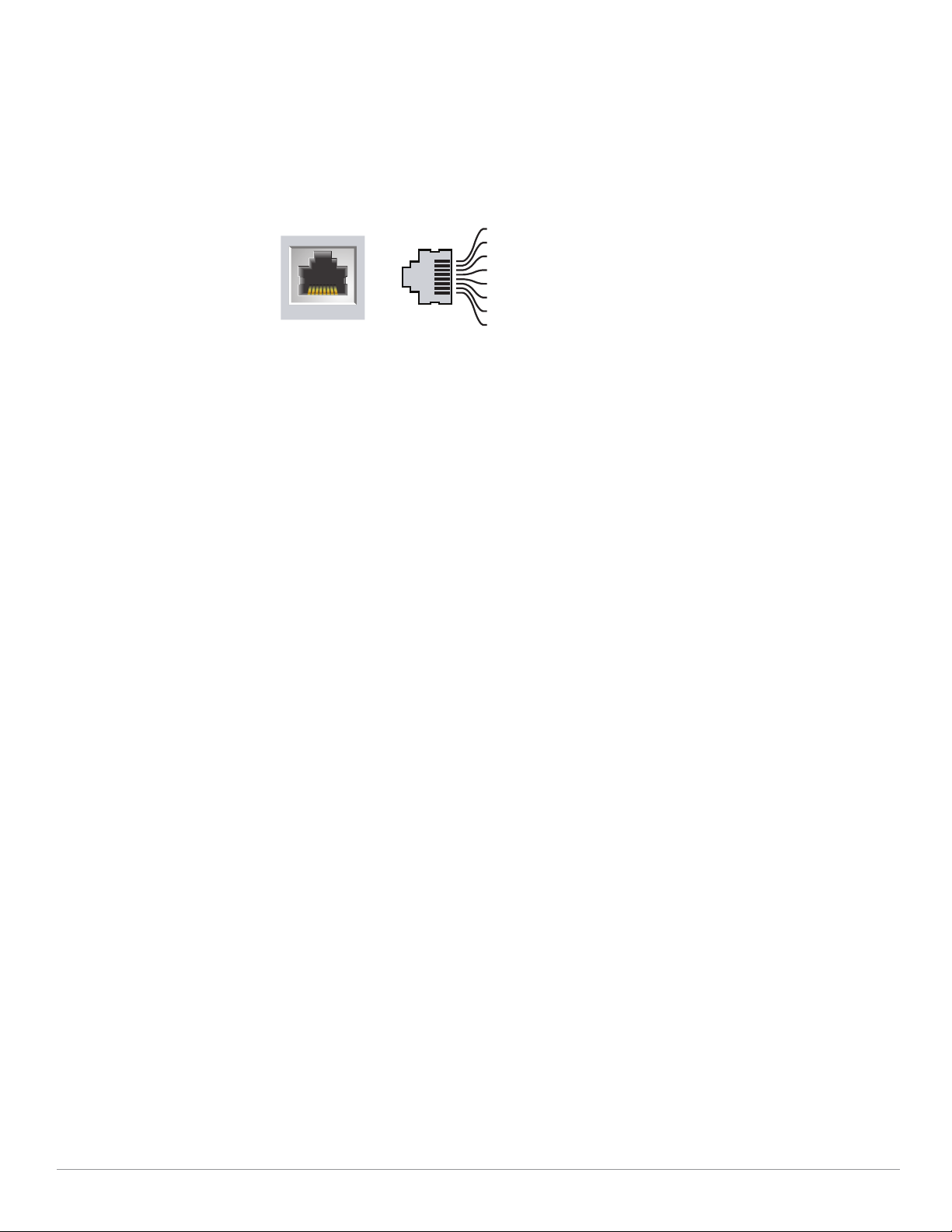
The E0 port is a 100/1000/2500Base-T, auto-sensing MDI/MDX, which supports uplink connectivity
1000Base-T Gigabit
Ethernet Port
RJ-45 Female
Pin-Out
Signal Name
1
2
3
4
5
6
7
8
BI_DC+
BI_DC-
BI_DD+
BI_DD-
BI_DA+
BI_DABI_DB+
BI_DB-
Function
Bi-directional pair +C
Bi-directional pair -C
Bi-directional pair +D
Bi-directional pair -D
Bi-directional pair +A
Bi-directional pair -A
Bi-directional pair +B
Bi-directional pair -B
when linked by an Ethernet cable.
The E1 port is 100/1000Base-T auto-sensing MDI/MDX, which support downlink connectivity.
These ports may be used to provide secure network connectivity and also allows for manual
configuration the device when linked by an Ethernet cable.
Refer to Figure 5 for a detailed port pin-out.
Figure 5
Ethernet Port Pin-Out
Kensington Lock Slot
The 340 Series is equipped with a Kensington lock slot for additional security
USB Interface
The top of this access point is equipped with a USB-A port that is compatible with cellular modems.
When active, this port can supply up to 5W/1A to a connected device.
Push Button
The push button located on the bottom of the device can be used to reset the access point to factory
default settings or turn off/on the LED display.
To reset the access point to factory default settings:
1. Power off the access point.
2. Press and hold the push button using a small, narrow object, such as a paperclip.
3. Power-on the access point without releasing the push button. The System Status LED will flash
within 5 seconds.
4. Release the push button.
The system status LED will flash again within 15 seconds indicating that the reset is completed. The
access point will now continue to boot with the factory default settings.
To turn off/on the LED display:
During the normal operation of the access point, press and release the push button using a small,
narrow object, such as a paperclip.
Aruba 340 Series Access Points |Installation Guide 5
Power
The E0 and E1 ports support PoE-in from 802.3af and 802.3at power sources.
When powered by an Maximum power consumption for PoE 802.3af is 25W
If a PoE source is unavailable, an AP-AC-48V36C power cord (ordered separately) may be used to
connect the power socket, located at the back of the access point, to a DC power source.
The maximum power consumption from a DC source is 30W.
When an Aruba 340 Series access point is powered by both DC and PoE power sources
simultaneously, the DC power source is prioritized, while a small current is drawn from the PoE
source. Likewise, when an Aruba 340 Series access point is powered by two PoE sources
simultaneously, the 802.3at power source is prioritized, while a small current is drawn from the
802.3af source.
In the event that the primary power source fails, the small current drawn from the secondary source
will keep the access point alive, allowing for a hitless failover.
Intelligent Power Management (IPM) mode reports the access point’s power consumption and
enables intelligent management solutions to optimize energy efficiency.

Before You Begin
Refer to the sections below before beginning the installation process.
Pre-Installation Checklist
Before installing your Aruba 340 Series access point, be sure that you have one of the following:
Cat5E UTP cable with network access installed in the wall box
Aruba DC power cord
One of the following network services:
Aruba Discovery Protocol (ADP)
DNS server with an “A” record
DHCP Server with vendor-specific options
Identifying Specific Installation Locations
This access point should be oriented vertically, with rubber pads facing downward to facilitate
maximum antenna gain. Use the access point placement map generated by Aruba RF Plan software
application to determine the proper installation location(s). Each location should be as close as
possible to the center of the intended coverage area and should be free from obstructions or obvious
sources of interference. These RF absorbers/reflectors/interference sources will impact RF
propagation and should be accounted for during the planning phase and adjusted for in RF plan.
Identifying Known RF Absorbers/Reflectors/Interference Sources
Identifying known RF absorbers, reflectors, and interference sources while in the field during the
installation phase is critical. Make sure that these sources are taken into consideration when you
attach an access point to its fixed location.
RF absorbers include:
Cement/concrete—Old concrete has high levels of water dissipation, which dries out the concrete,
allowing for potential RF propagation. New concrete has high levels of water concentration in the
concrete, blocking RF signals.
Natural Items—Fish tanks, water fountains, ponds, and trees
Brick
RF reflectors include:
Metal Objects—Metal pans between floors, rebar, fire doors, air conditioning/heating ducts, mesh
windows, blinds, chain link fences (depending on aperture size), refrigerators, racks, shelves, and
filing cabinets.
Do not place an access point between two air conditioning/heating ducts. Make sure that access
points are placed below ducts to avoid RF disturbances.
RF interference sources include:
Microwave ovens and other 2.4 or 5 GHz objects (such as cordless phones)
Cordless headset such as those used in call centers or lunch rooms
Access Point Installation
The Aruba 340 Series access point is designed for office deployments and may be fastened to a ceiling tile rail
using the mount adapters provided. Additional wall mount adapters and ceiling rail adapters for other rail styles
6 Aruba 340 Series Access Points | Installation Guide

are available as accessory kits, which may be purchased separately.
!
All Aruba access points should be professionally installed by an Aruba-Certified Mobility Professional (ACMP).
The installer is responsible for ensuring that grounding is available and meets applicable national and electrical
codes. Failure to properly install this product may result in physical injury and/or damage to property.
Tous les points d'accès Aruba doivent impérativement être installés par un professionnel agréé. Ce dernier doit
s'assurer que l'appareil est mis à la terre et que le circuit de mise à la terre est conforme aux codes électriques
nationaux en vigueur. Le fait de ne pas installer correctement ce produit peut entraîner des blessures
corporelles et / ou des dommages matériels.
Use the steps in this section to install the 340 Series access point.
1. Pull the necessary cables through a prepared hole in the ceiling tile near where the AP will be placed.
2. Place the adapter against the back of the AP with the adapter at an angle of approximately 30 degrees to the
tabs, then twist the adapter clockwise until it snaps into place onto the tabs (see Figure 6).
Figure 6 Attaching the Ceiling Rail Adapter
3. If necessary, connect the console cable to the console port on the back of the access point.
4. Hold the access point next to the ceiling tile rail with the ceiling tile rail mounting slots at approximately a 30degree angle to the ceiling tile rail (see Figure 5). Make sure that any cable slack is above the ceiling tile.
5. Pushing toward the ceiling tile, rotate the AP clockwise until the device clicks into place on the ceiling tile rail.
Ensure that the AP is locked into the ceiling rail mount before completing the installation.
6. (Optional) When installing the AP-344, connect the external antennas connectors on the front of the access
point.
Aruba 340 Series Access Points |Installation Guide 7

Figure 7 Mounting the AP
AP-204_04
!
Software
For instructions on choosing operating modes and initial software configuration, refer to the Access
Point Software Quick Start Guide.
Verifying Post-Installation Connectivity
The integrated LED on the access point can be used to verify that the access point access point is
receiving power and initializing successfully (see Tabl e 1
-4). Refer to the Aruba Access Point Software
Quick Start Guide for further details on verifying post-installation network connectivity.
Environmental Specifications
For additional specifications on this product, please refer to the product data sheet at
arubanetworks.com
Operating:
Temperature: 0°C to +40°C (+32°F to +104°F)
Humidity: 5% to 93% non-condensing
Storage and transport:
Temperature: -40°C to +70°C (-40°F to +158°F)
Humidity: 5% to 93% non-condensing
RF Radiation Exposure Statement: This equipment complies with FCC RF radiation exposure limits. This
equipment should be installed and operated with a minimum distance of 7.87 inches (20cm) between the
radiator and your body for 2.4 GHz and 5 GHz operations. This transmitter must not be co-located or operating
in conjunction with any other antenna or transmitter. When operated in 5.15 to 5.25 GHz frequency range, this
device is restricted to indoor use to reduce the potential for harmful interference with co-channel Mobile
Satellite Systems.
Déclaration sur les limites d'exposition aux radiofréquences : cet équipement est conforme aux limites
d'exposition aux rayonnements radioélectriques spécifiées par la FCC. Il doit être installé et utilisé à une distance
minimale de 20 cm par rapport à votre corps pour les fréquences de 2,4 et 5 GHz. Cet émetteur-récepteur ne
doit pas être utilisé ou situé à proximité d'autres antennes ou émetteurs-récepteurs. En cas d'utilisation dans la
plage de fréquences de 5,15 à 5,25 GHz, cet appareil doit uniquement être utilisé en intérieur afin de réduire les
risques d'interférence avec les systèmes satellites mobiles partageant le même canal.
8 Aruba 340 Series Access Points | Installation Guide

Proper Disposal of Aruba Equipment
Dispose of Aruba products per local regulation. For the most current information about Global
Environmental Compliance and Aruba products, see our website at www.arubanetworks.com.
Waste of Electrical and Electronic Equipment
Aruba products at end of life are subject to separate collection and treatment in the
EU Member States, Norway, and Switzerland and therefore are marked with the
symbol shown at the left (crossed-out wheelie bin). The treatment applied at end of
life of these products in these countries shall comply with the applicable national
laws of countries implementing Directive 2002/96EC on Waste of Electrical and
Electronic Equipment (WEEE).
China RoHS
Aruba products also comply with China environmental declaration requirements and are packaged
with the “EFUP10” label shown below.
Aruba 340 Series Access Points |Installation Guide 9

Taiwan
European Union RoHS
Aruba products comply with the EU Restriction of Hazardous Substances Directive 2011/65/EC
(RoHS). EU RoHS restricts the use of specific hazardous materials in the manufacture of electrical and
electronic equipment. Specifically, restricted materials under the RoHS Directive are Lead (including
Solder used in printed circuit assemblies), Cadmium, Mercury, Hexavalent Chromium, and Bromine.
Some Aruba products are subject to the exemptions listed in RoHS Directive Annex 7 (Lead in solder
used in printed circuit assemblies).
India RoHS
This product complies with RoHS requirements as prescribed by E-Waste (Management & Handling)
Rules, governed by the Ministry of Environment & Forests, Government of India.
Turkey RoHS
Ukraine RoHS
Regulatory Information
For the purpose of regulatory compliance certifications and identification, this product has been
assigned a unique regulatory model number. The regulatory model number can be found on the
product nameplate label, along with all required approval markings and information. When
requesting compliance information for this product, always refer to this regulatory model number.
The regulatory model number is not the marketing name or model number of the product.
AP-344: APIN0344
10 Aruba 340 Series Access Points | Installation Guide

AP-345: APIN0345
!
!
Changes or modifications to this unit not expressly approved by the party responsible for regulatory compliance
could void the user’s authority to operate this equipment.
Toute modification effectuée sur cet équipement sans l'autorisation expresse de la partie responsable de la
conformité est susceptible d'annuler son droit d'utilisation.
Federal Communication Commission
This device complies with Part 15 of the FCC Rules. Operation is subject to the following two
conditions: (1)this device may not cause harmful interference, and (2) this device must accept any
interference received, including interference that may cause undesired operation.
This equipment has been tested and found to comply with the limits for a Class B digital device,
pursuant to Part 15 of the FCC Rules. These limits are designed to provide reasonable protection
against harmful interference in a residential installation. This equipment generates, uses, and can
radiate radio frequency energy and, if not installed and used in accordance with the instructions, may
cause harmful interference to radio communications. However, there is no guarantee that
interference will not occur in a particular installation. If this equipment does cause harmful
interference to radio or television reception, which can be determined by turning the equipment off
and on, the user is encouraged to try to correct the interference by one or more of the following
measures:
Reorient or relocate the receiving antenna.
Increase the separation between the equipment and receiver.
Connect the equipment into an outlet on a circuit that is different from that to which the receiver
is connected.
Consult the dealer or an experienced radio or television technician for help.
Improper termination of access points installed in the United States configured to a non-US model controller is a
violation of the FCC grant of equipment authorization. Any such willful or intentional violation may result in a
requirement by the FCC for immediate termination of operation and may be subject to forfeiture (47 CFR 1.80).
The network administrator(s) is/are responsible for ensuring that this device operates in accordance with local/
regional laws of the host domain.
European Union
The Declaration of Conformity made under RED Directive 2014/53/EU is available for viewing at:
arubanetworks.com, then navigate to the Declarations of Conformity > Access Point folder, select
the document that corresponds to your device’s model number as it is indicated on the product label.
Wireless Channel Restrictions
5150-5250MHz band is limited to indoor only in the following countries; Austria (AT), Belgium (BE),
Bulgaria (BG), Croatia (HR), Cyprus (CY), Czech Republic (CZ), Denmark (DK), Estonia (EE), Finland (FI),
France (FR), Germany (DE), Greece (GR), Hungary (HU), Iceland (IS), Ireland (IE), Italy (IT), Latvia (LV),
Liechtenstein (LI), Lithuania (LT), Luxembourg (LU), Malta (MT), Netherlands (NL), Norway (NO),
Poland (PL), Portugal (PT), Romania (RO), Slovakia (SK), Slovenia (SL), Spain (ES), Sweden (SE),
Switzerland (CH), Turkey (TR), United Kingdom (UK).
Frequency Range MHz Max EIRP
2412-2472 20 dbm
5150-5250 23 dbm
5250-5350 23 dbm
5470-5725 30 dbm
Aruba 340 Series Access Points |Installation Guide 11

Frequency Range MHz Max EIRP
!
5725-5850 N/A for EU
Lower power radio LAN product operating in 2.4 GHz and 5 GHz bands. Please refer to the ArubaOS User Guide/
Instant User Guide for details on restrictions.
Produit réseau local radio basse puissance operant dans la bande fréquence 2.4 GHz et 5 GHz. Merci de vous
referrer au ArubaOS User Guide/Instant User Guide pour les details des restrictions.
Low Power FunkLAN Produkt, das im 2.4 GHz und im 5 GHz Band arbeitet. Weitere Informationen bezlüglich
Einschränkungen finden Sie imArubaOS User Guide/Instant User Guide.
Apparati Radio LAN a bassa Potenza, operanti a 2.4 GHz e 5 GHz. Fare riferimento alla ArubaOS User Guide/
Instant User Guide per avere informazioni detagliate sulle restrizioni.
Industry Canada
This Class B digital apparatus meets all of the requirements of the Canadian Interference-Causing
Equipment Regulations.
In accordance with Industry Canada regulations, this radio transmitter and receiver may only be used
with an antenna, the maximum type and gain of which must be approved by Industry Canada. To
reduce po tential radio interference, the type of antenna and its gain shall be chosen so that the
equivalent isotropic radiated power (EIRP) does not exceed the values necessary for effective
communication.
This device complies with Industry Canada's license-exempt RSS regulations. Operation of this device
is subject to the following two conditions: (1) this device may not cause interference, and (2) this
device must accept any interference, including interference that may cause undesired operation.
Déclaration d’Industrie Canada
Conformément aux réglementations d’Industrie Canada, cet émetteur-récepteur radio doit être
utilisé uniquement avec une antenne dont le type et le gain maximal doivent être approuvés par
Industrie Canada. Pour réduire les interférences radio potentielles, le type d’antenne et son gain
doivent être choisis de façon à ce que la puissance isotrope rayonnée équivalente (PIRE) ne dépasse
pas les valeurs nécessaires à une communication efficace.
Ce périphérique est conforme aux règlements RSS exempts de licence d’Industrie Canada.
L’u til is ation de c e pér ip hériq ue est soumi se au x de ux conditions suivantes : (1) ce périphérique ne
doit pas provoquer d’interférences, et (2) ce périphérique doit accepter toute interférence, y compris
les interférences susceptibles de provoquer un dysfonctionnement.
12 Aruba 340 Series Access Points | Installation Guide

Japan
Brazil
Este equipamento opera em caráter secundário, isto é, não tem direito a proteção contra
interferência prejudicial, mesmo de estações do mesmo tipo, e não pode causar interferência a
sistemas operando em caráter primário.
Mexico
La operación de este equipo está sujeta a las siguientes dos condiciones: (1) es posible que este
equipo o dispositivo no cause interferencia perjudicial y (2) este equipo o dispositivo debeaceptar
cualquier interferencia, incluyendo la que pueda causar su operación no deseada.
Korean
Taiwan
Medical
1. Equipment not suitable for use in the presence of flammable mixtures.
2. Connect to only IEC 60950-1 or IEC 60601-1 3rd edition certified products and power sources. The end user is
responsible for the resulting medical system complies with the requirements of IEC 60601-1 3rd edition.
3. Wipe with a dry cloth, no additional maintenance required.
4. No serviceable parts, the unit must be sent back to the manufacturer for repair.
5. No modifications are allowed without Aruba approval.
Aruba 340 Series Access Points |Installation Guide 13

Copyright
© Copyright 2017 Hewlett Packard Enterprise Development LP
Open Source Code
This product includes code licensed under the GNU General Public License, the GNU Lesser General Public License, and/or certain other open
source licenses.
A complete machine-readable copy of the source code corresponding to such code is available upon request. This offer is valid to anyone in
receipt of this information and shall expire three years following the date of the final distribution of this product version by Hewlett Packard
Enterprise Company.
To obtain such source code, send a check or money order in the amount of US
$10.00 to:
Hewlett Packard Enterprise Company
Attn: General Counsel
3000 Hanover Street
Palo Alto, CA 94304
USA
Warranty
This hardware product is protected by an Aruba warranty.
For more details visit www.hpe.com/us/en/support.html and select the “HPE Servers, Storage, and Networking” option from the Product Support
menu to access HPE’s Warranty Check.
a Hewlett Packard
Enterprise company
3333 Scott Boulevard
Santa Clara, California 95054
USA
14 Aruba 340 Series Access Points |Installation Guide
 Loading...