

Page 1
Aruba 387 Series Outdoor Access Points
Installation Guide
The Aruba 387 Series access points are equipped with two radios (a 5GHz 802.11ac radio and a 60GHz 802.11ad
radio), delivering high performance with the MU-MIMO (Multi-User Multiple-Input, Multiple-Output) technology,
supporting 802.11a/n/ac/ad wireless services. The 387 Series access point can be deployed in either a controllerbased (ArubaOS) or controller-less (InstantOS) deployment mode.
Guide Overview
“Hardware Overview” on page2 provides a detailed hardware overview of the 387 Series access points.
“Before You Begin” on page4 provides key questions to ask and items to consider when deploying an
outdoor wireless network.
“Installing the Access Point” on page6 describes the multi-step process for a successful installation and
deployment of the 387 Series access points.
“Safety and Regulatory Compliance” on page8 provides an overview of safety and regulatory compliance
information.
Package Contents
387 Series access point
USB console cable x1
Cable gland x1
Ground stud bolt and washer x1
The weatherproof caps for Ethernet and Console interfaces are connected to the access point, not loose in the
package.
Mounting kits for use with the 387 Series access points are sold separately. Contact your Aruba sales
representative for details.
Inform your supplier if there are any incorrect, missing, or damaged parts. If possible, retain the carton,
including the original packing materials. Use these materials to repack and return the unit to the supplier if
needed.
Rev 02 | January 2019 1
Page 2
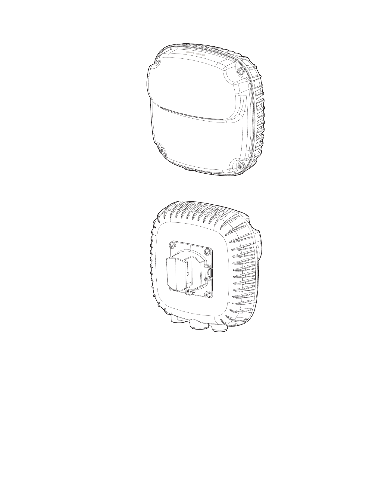
Hardware Overview
Figure 1 AP-387 Front View
Figure 2 AP-387 Back View
2 Aruba 387 Series Outdoor Access Points | Installation Guide
Page 3
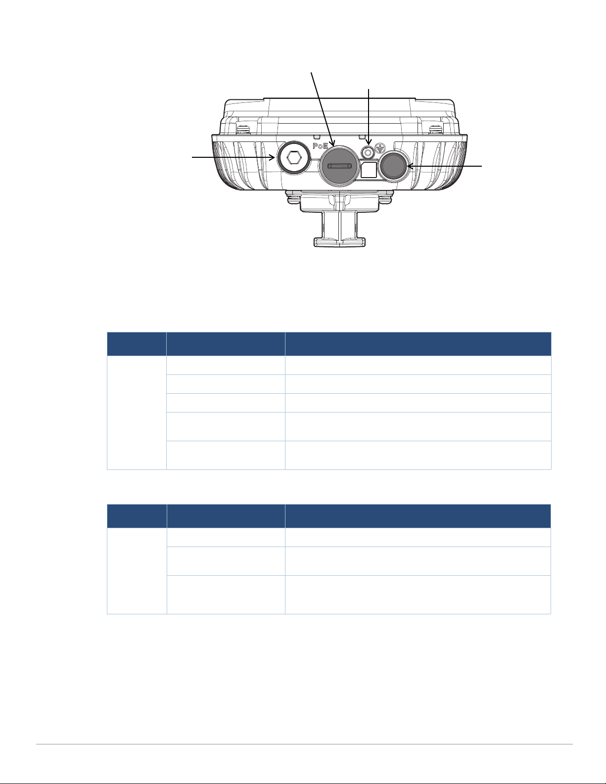
Figure 3 AP-387 Bottom View
Grounding Point
Air Vent
Ethernet Port
USB Console Port,
Reset button and
LED
LED
The 387 Series access point is equipped with one LED that indicates the system status of the access point.
Table 1 387 Series LED Meanings during Boot Up
LED Color/State Meaning
System LED Off No power to AP
Red Initial power-up
Green - Flashing AP booting
Green - Steady AP ready and 1000Mbps Ethernet link established. The LED turns
off after 1200 seconds
Green - Yellow, 6 seconds
period
AP ready and 10/100Mbps Ethernet link established. The LED
turns off after 1200 seconds
Table 2 387 Series LED Meanings during Operation
LED Color/State Meaning
System LED Solid Red General fault
One blink off every 3
seconds
Two quick blink off 0.5
seconds apart cycled every
3 seconds
Radio 0 fault (5GHz)
Radio 1 fault (60GHz)
Aruba 387 Series Outdoor Access Points | Installation Guide 3
E0/POE
The 387 Series access point is equipped with one 100/1000 Base-T auto-sensing MDI/MDX Ethernet port (E0) for
wired network connectivity. This port supports IEEE 802.3at Power over Ethernet (PoE) compliance, allowing the
387 Series access point to be powered from an 802.3at compliant PoE power supply.
Grounding Point
Always remember to protect the access point by installing grounding lines. The ground connection must be
complete before connecting power to the access point enclosure.
Page 4
USB Console Port
!
CAUTION
The USB Micro-B console port allows you to connect the access point to a laptop or serial console for direct
management. Use the included USB console cable to connect the access point. You can download the necessary
driver for USB-UART adapter from support.arubanetworks.com under the Tools & Resources tab.
You need a proper Allen wrench (8mm) to open the cover of the USB Console port.
Use the following setting to access the terminal:
Table 3 Console Settings
Baud Rate Data Bits Parity Stop Bits Flow Control
9600 8 None 1 None
Reset Button
To reset a 387 Series access point to factory default settings:
1. Press and hold down the reset button using a small, narrow object such as a paper clip while the 387 Series
access point is not powered.
2. Connect the PoE power supply to the 387 Series access point while the reset button is being held down.
3. Release the reset button on the 387 Series access point after 15 seconds.
Before You Begin
FCC Statement: Improper termination of access points installed in the United States configured to non-US
model controllers will be in violation of the FCC grant of equipment authorization. Any such willful or
intentional violation may result in a requirement by the FCC for immediate termination of operation and may
be subject to forfeiture (47 CFR 1.80).
Pre-Installation Network Requirements
If the 387 Series access point is deployed in controller-based (ArubaOS) mode, after WLAN planning is complete
and the appropriate products and their placement have been determined, the Aruba controller(s) must be
installed and initial setup performed before the Aruba access points are deployed. For initial setup of the
controller, refer to the ArubaOS Quick Start Guide for the software version installed on your controller. If the 387
Series access point is deployed in Instant mode, no controllers are needed. For procedures involved in deploying
the access point in ArubaOS and Instant modes, refer to the AP Software Quick Start Guide by visiting the
Documentation tab on support.arubanetworks.com, and then selecting Software User & Reference Guides >
Aruba Unified.
Pre-Installation Checklist
Before installing your 387 Series access point, be sure that you have the following:
CAT5E UTP cable or better
IEEE 802.3at compliant PoE source
For 387 Series access point running ArubaOS only:
Aruba controller provisioned on the network
Layer 2/3 network connectivity to your access point
One of the following network services:
Aruba Discovery Protocol (ADP)
DNS server with an “A” record
4 Aruba 387 Series Outdoor Access Points | Installation Guide
Page 5

DHCP Server with vendor specific options
!
CAUTION
Aruba in compliance with governmental requirements, has designed the 387 Series access points so that only
authorized network administrators can change configuration settings. For more information about AP
configuration, refer to the ArubaOS Quick Start Guide and ArubaOS/Instant User Guide.
Access points are radio transmission devices and as such are subject to governmental regulation. Network
administrators responsible for the configuration and operation of access points must comply with local
broadcast regulations. Specifically, access points must use channel assignments appropriate to the location in
which the access point will be used.
Verifying Pre-Installation Connectivity
The instructions in this section are applicable to the 387 Series access points running ArubaOS only.
Before you install access points in a network environment, make sure that the access points will be able to locate
and connect to the controller when they are powered on. Specifically, you must verify the following conditions:
When connected to the network, each access point is assigned a valid IP address.
Access points are able to locate the controller.
Refer to the ArubaOS Quick Start Guide for instructions on locating and connecting to the controller.
Outdoor Planning and Deployment Considerations
Prior to deploying an outdoor wireless network, the environment must be evaluated to plan for a successful
WLAN deployment. Successfully evaluating the environment enables the proper selection of routers and
antennas and assists in the determination of their placement for optimal RF coverage. This process is considered
WLAN or RF planning and Aruba’s system engineers can assist in the outdoor planning process.
The rules for the 5600-5650 MHz band vary by region.
Identifying Specific Installation Locations
You can mount the 387 Series access point on a wall or pole. Each location should be as close as possible to the
center of the intended coverage area and should be free from obstructions or obvious sources of interference.
These RF absorbers/reflectors/interference sources will impact RF propagation and should have been accounted
for during the planning phase and adjusted for in RF plan.
Identifying Known RF Absorbers/Reflectors/Interference Sources
Identifying known RF absorbers, reflectors, and interference sources while in the field during the installation
phase is critical. Make sure that these sources are taken into consideration when you attach an AP to its fixed
location. Examples of sources that degrade RF performance include:
Cement and brick
Objects that contain water
Metal
Microwave ovens
Wireless phones and headsets
Aruba 387 Series Outdoor Access Points | Installation Guide 5
Page 6

Installing the Access Point
Service to all Aruba products should be performed by trained service personnel only.
Using Mount Kits
The 387 Series access point can be installed on a wall or attached to a pole by using mount kits:
Table 4 Applicable Mount Kits for 387 Series Access Point
Part Number Description
JW054A AP-270-MNT-H1 mount kit for hanging from inclined or horizontal structure.
JW055A AP-270-MNT-H2 flush mount kit for wall and ceiling mounting.
The 387 Series access point does not ship with any mount kits. These mount kits are available as accessories
and must be ordered separately.
For installation instructions on AP-270-MNT-H1 and AP-270-MNT-H2 mount kits, please refer to the AP-270-
MNT-H1 Installation Guide and AP-270-MNT-H2 Installation Guide respectively.
To ensure successful point-to-point connection, the 387 Series access points should mount face to face as shown
in Figure 4.
Figure 4 Mounting AP-387 Face to Face
Grounding the Access Point
The grounding must be completed before powering up the access point. The grounding wire should be #8 AWG.
1. Peel the cover of one end of the grounding wire and place the bare grounding wire into the included copper
lug, and press firmly with the crimping pliers.
2. Fasten the copper lug to the grounding hole on the access point with the included M4 x6 screw.
6 Aruba 387 Series Outdoor Access Points | Installation Guide
Page 7

Connecting the Ethernet Cable
!
CAUTION
Sealing Nut
Clip
Gland Body
Split Grommet
To connect the Ethernet cable to the access point, perform the following steps using the Ethernet cable glands
that ships with your access point.
Failure to use the included Ethernet cable glands can lead to connectivity and POE issues.
The cable is not included and must be purchased separately. Purchase a suitable UV-resistant, outdoor rated,
CAT 5E or better RJ45 cable for use with the access point.
Figure 5 Installing the Ethernet Cable Gland
1. Remove the dust cap from the Ethernet port
2. Slide the sealing nut, clip, split grommet and gland body over the cable.
3. Insert the RJ45 connector to the Ethernet port.
4. Screw the gland body onto the Ethernet port.
5. Combine the two split parts of the grommet over the cable, and move it towards the gland body until it
locates at the recess of the gland body.
6. Move the clip towards the gland body, passing over the grommet, until the wavy end of the clip properly fits
into the wavy end of the gland body.
7. Screw the sealing nut onto the gland body.
Two grommets are provided in the package for use with the Ethernet cables. One is applicable for cables with
4-6 mm diameter, and another is applicable for cables with 6-10 mm diameter.
Verifying Post-Installation Connectivity
The integrated LEDs on the access point can be used to verify that the access point is receiving power and
initializing successfully (see Table 1 and Table 2). For instructions on initial setup and software configuration,
refer to the AP Software Quick Start Guide.
Electrical and Environmental Specifications
Electrical
Ethernet
One 100/1000Base-T auto-sensing Ethernet RJ-45 Interfaces
Power over Ethernet (IEEE 802.3at compliant)
Environmental
Operating
Aruba 387 Series Outdoor Access Points | Installation Guide 7
Page 8

Temperature: -40ºC to 60ºC (-40ºF to 140ºF)
!
CAUTION
!
CAUTION
!
CAUTION
!
CAUTION
!
CAUTION
Storage
Temperature: -40ºC to 70ºC (-40ºF to 158ºF)
Humidity: 5% to 93% non-condensing
For additional specifications on this product, please refer to the data sheet at www.arubanetworks.com.
Regulatory Model Number
The regulatory model number (RMN) for 387 Series:
AP-387: APEX0387
Safety and Regulatory Compliance
FCC
To view the FCC ID for controller-managed access points:
1. Log into the controller WebUI
2. Navigate to Maintenance > Controller > About
To view the FCC ID for Instant access points:
1. Log into the virtual controller WebUI
2. Navigate to Maintenance > About
RF Radiation Exposure Statement: This equipment complies with RF radiation exposure limits. This
equipment should be installed and operated with a minimum distance of 14.96 inches (38cm) between the
radiator and your body for 5GHz and 60GHz operations. This transmitter must not be co-located or operating
in conjunction with any other antenna or transmitter.
Déclaration de la concernant l’exposition aux rayonnements à fréquence radioélectrique (FR): Cet
appareil est conforme aux limites d’exposition aux rayonnements FR établies. Il doit être installé et utilisé à une
distance minimale de 38 cm (14.96 pouces) entre le radiateur et votre corps, qu’il opère sur la bande 5GHz ou
60GHz. Cet émetteur ne doit pas être installé ou utilisé à proximité immédiate d’une autre antenne ni d’un
autre transmetteur.
The device could automatically discontinue transmission in case of absence of information to transmit, or
operational failure. Note that this is not intended to prohibit transmission of control or signaling information
or the use of repetitive codes where required by the technology.
Changes or modifications to this unit not expressly approved by the party responsible for compliance could
void the user’s authority to operate this equipment.
Toute modification effectuée sur cet équipement sans l'autorisation expresse de la partie responsable de la
conformité est susceptible d'annuler son droit d'utilisation.
FCC Class B Part 15
This equipment has been tested and found to comply with the limits for a Class B digital device, pursuant to Part
15 of the FCC Rules. These limits are designed to provide reasonable protection against harmful interference in a
residential installation. This equipment generates, uses and can radiate radio frequency energy and, if not
installed and used in accordance with the manufacturer’s instructions, may cause harmful interference to radio
communications.
8 Aruba 387 Series Outdoor Access Points | Installation Guide
Page 9

However, there is no guarantee that interference will not occur in a particular installation. If this equipment does
cause harmful interference to radio or television reception, which can be determined by turning the equipment
off and on, the user is encouraged to try to correct the interference by one or more of the following measures:
Reorient or relocate the receiving antenna.
Increase the separation between the equipment and receiver.
Connect the equipment to an outlet on a circuit different from that to which the receiver is connected.
Consult the dealer or an experienced radio or TV technician for help.
Canada
This device complies with ISED’s license-exempt RSS standard(s).
Operation is subject to the following two conditions: (1) this device may not cause interference, and (2) this
device must accept any interference, including interference that may cause undesired operation of the device.
When operated in the 5.15 to 5.25 GHz frequency range, this device is restricted to indoor use to reduce the
potential for harmful interference with co-channel Mobile Satellite Systems.
Déclaration d’Industrie Canada
Le présent appareil est conforme aux CNR d'Industrie Canada applicables aux appareils radio exempts de
licence. L'exploitation est autorisée aux deux conditions suivantes : (1) l'appareil ne doit pas produire de
brouillage, et (2) l'utilisateur de l'appareil doit accepter tout brouillage radioélectrique subi, même si le brouillage
est susceptible d'en compromettre le fonctionnement.
Professional Installation Instruction
This product is designed for specific application and needs to be installed by a qualified personal who has RF and
related rule knowledge. The general user shall not attempt to install or change the setting.
The product shall be installed at a location where the radiating antenna can be kept 14.96 inches (38cm) from
nearby person in normal operation condition to meet regulatory RF exposure requirement.
Please carefully select the installation position and make sure that the final output power does not exceed the
limit set force in relevant rules. The violation of the rule could lead to serious federal penalty.
Instructions d'installation professionnelle
Ce produit est destine a un usage specifique et doit etre installe par un personnel qualifie maitrisant les
radiofrequences et les regles s'y rapportant. L'installation et les reglages ne doivent pas etre modifies par
l'utilisateur final.
En usage normal, afin de respecter les exigences reglementaires concernant l'exposition aux radiofrequences,
ce produit doit etre installe de facon a respecter une distance de 14.96 inches (38cm) entre l'antenne emettrice
et les personnes.
Choisir avec soin la position d'installation et s'assurer que la puissance de sortie ne depasse pas les limites en
vigueur. La violation de cette regle peut conduire a de serieuses penalites federales.
EU Regulatory Conformance
Aruba hereby declares that the 387 Series wireless access points are in compliance with directives listed
below
:
Radio Equipment Directive 2014/53/EU
REACH Regulation (EC) No.: 1907/2006
RoHS Directive 2011
WEEE Directive 2012
The Declaration of Conformity made under Radio Equipment Directive 2014/53/EU is available for viewing at:
www.hpe.com/eu/certificates. Select the document that corresponds to your device’s model number as it is
indicated on the product label
Medical
1. Equipment not suitable for use in the presence of flammable mixtures.
2. Connect to only IEC 60950-1 or IEC 60601-1 certified products and power sources. The end user is
responsible for the resulting medical system complies with the requirements of IEC 60601-1.
3. Wipe with a dry cloth, no additional maintenance required.
Aruba 387 Series Outdoor Access Points | Installation Guide 9
Page 10

4. No serviceable parts, the unit must be sent back to the manufacturer for repair.
!
CAUTION
!
CAUTION
!
CAUTION
5. No modifications are allowed without Aruba approval.
This device intended to be installed outdoors.
This device has no IEC/EN60601-1-2 essential performance.
Use of this equipment adjacent to or stacked with other equipment should be avoided because it could result
in improper operation. If such use is necessary, this equipment and the other equipment should be observed
to verify that they are operating normally.
Compliance is based on the use of Aruba approved accessories. Refer to the ordering guide for this access
point at www.arubanetworks.com.
Use of accessories, transducers and cables other than those specified or provided by the manufacturer of this
equipment could result in increased electromagnetic emissions or decreased electromagnetic immunity of this
equipment and result in improper operation.
Portable RF communications equipment (including peripherals such as antenna cables and external antennas)
should be used no closer than 30 cm (12 inches) to any part of the access point. Otherwise, degradation of the
performance of this equipment could result.
The emissions characteristics of this equipment make it suitable for use in industrial areas and hospitals (CISPR
11 class A). If it is used in a residential environment (for which CISPR 11 class B is normally required) this
equipment might not offer adequate protection to radio-frequency communication services. The user might
need to take mitigation measures, such as relocating or re-orienting the equipment.
Radio Type Frequency Range Power (EIRP) Modulation
BLE 2400-2483.5MHz <10dBm GFSK
802.11 5150-5250MHz 23dBm OFDM
802.11 5250-5350MHz 23dBm OFDM
802.11 5500-5700MHz 30dBm OFDM
802.11 5725-5850MHz 14dBm OFDM
802.11ad 57-66GHz 40dBm OFDM
Actual output power values will depend on national restrictions and the antennas used.
Emissions Complies with CISPR11/EN55011, Group 1, Class B
Immunity
10 Aruba 387 Series Outdoor Access Points | Installation Guide
Page 11

Electrostatic discharge: +/-8kV contact/ +/-15kV air
Radiated RF EM fields: 80MHz - 2.7GHz, 3V/m
Proximity fields from RF wireless communication
equipment:
RATED power frequency magnetic fields: 30A/m
Electrical Fast Transients: +/-2kV
Surges (line-to-line): +/- 0.5, 1.0
Surges (line-to-ground): +/- 0.5, 1.0, 2kV
Conducted disturbances induced by RF fields: 0.15MHz-80MHz, 3Vrms
Voltage Dips: 0%, 0.5 cycles, 0%, 1 cycle, 70% 25/30 cycles
Voltage Interruptions: 0% 250/300 cycles
Per Table 9 of the IEC/EN 606010-1-2
Brazil
Este equipamento não tem direito à proteção contra interferência prejudicial e não pode causar interferência
em sistemas devidamente autorizados.
Japan
México
La operación de este equipo está sujeta a las siguientes dos condiciones: (1) es posible que este equipo o
dispositivo no cause interferencia perjudicial y (2) este equipo o dispositivo debeaceptar cualquier interferencia,
incluyendo la que pueda causar su operación no deseada.
Morocco
Нормативные требования Евразийского Экономического Союза
HPE Russia: ООО "Хьюлетт Паккард Энтерпрайз" Российская Федерация, 125171, г.
Москва, Ленинградское шоссе, 16А, стр.3, Телефон : +7 499 403 4248 Факс: +7 499 403
4677
'HPE Belarus': ИООО «Хьюлетт-Паккард Бел», Республика Беларусь, 220030, г. Минск,
ул. Интернациональная, 36-1, Телефон/факс: +375 17 392 28 20
'HPE Kazakhstan': TOO «Хьюлетт-Паккард (К)», Республика Казахстан, 050040, г.
Алматы, Бостандыкский район, проспект Аль-Фараби, 77/7, Те лефон/факс: + 7 727 355 35 50
Aruba 387 Series Outdoor Access Points | Installation Guide 11
Page 12

Kazakhstan
ЖШС "Хьюлетт Паккард Энтерпрайз" Ресей Федерациясы, 125171, Мәскеу, Ленинград тас жолы, 16A блок
3, Телефон: +7 499 403 4248 Факс: +7 499 403 4677
«HEWLETT-PACKARD Bel» ЖШС, Беларусь Республикасы, 220030, Минск қ., Интернациональная көшесі, 36/
1, Телефон/факс: +375 17 392 28 20
ЖШС «Хьюлетт-Паккард (К)», Қазақстан Республикасы, 050040, Алматы к., Бостандык ауданы, Әл-Фараби
даңғ ылы, 77/7, Телефон/факс: +7 (727) 355 35 50
Taiwan
第十二條
經型式認證合格之低功率射頻電機,非經許可,公司、商號或使用者均不得擅自變更頻率、加大功率或變更原設計之特性及功
能。
第十四條
低功率射頻電機之使用不得影響飛航安全及干擾合法通信;經發現有干擾現象時,應立即停用,並改善至無干擾時方得繼續使
用。
前項合法通信,指依電信法規定作業之無線電通信。
低功率射頻電機須忍受合法通信或工業、科學及醫療用電波輻射性電 機設備之干擾。
12 Aruba 387 Series Outdoor Access Points | Installation Guide
Page 13

Contacting Support
Table 5 Contact Information
Main Site arubanetworks.com
Support Site support.arubanetworks.com
Airheads Social Forums and Knowledge
Base
North American Telephone 1-800-943-4526 (Toll Free)
International Telephones arubanetworks.com/support-services/contact-support/
Software Licensing Site hpe.com/networking/support
End of Support information arubanetworks.com/support-services/end-of-life-products/end-of-life-
Security Incident Response Team (SIRT) Site: arubanetworks.com/support-services/security-bulletins/
community.arubanetworks.com
1-408-754-1200
policy/
Email: sirt@arubanetworks.com
Copyright
© Copyright 2018 Hewlett Packard Enterprise Development LP
Open Source Code
This product includes code licensed under the GNU General Public License, the GNU Lesser General Public
License, and/or certain other open source licenses. A complete machine-readable copy of the source code
corresponding to such code is available upon request. This offer is valid to anyone in receipt of this information
and shall expire three years following the date of the final distribution of this product version by Hewlett Packard
Enterprise Company. To obtain such source code, send a check or money order in the amount of US $10.00 to:
Hewlett Packard Enterprise Company
Attn: General Counsel
3000 Hanover Street
Palo Alto, CA 94304
USA
Warranty
This hardware product is protected by an Aruba warranty. For more details visit www.hpe.com/us/en/
support.html
Aruba 387 Series Outdoor Access Points | Installation Guide 13
 Loading...