

Page 1

Aruba 80 Outdoor Wireless
Access Point
Models AP-80MB or AP-80SB
Professional Installation Guide
Page 2

Copyright
Copyright © 2005 Aruba Wireless Networks, Inc. All rights reserved.
Specifications in this manual are subject to change without notice.
Originated in the USA.
Trademarks
ArubaOS, AirOS, Aruba 800, Aruba 2400, Aruba 5000, Aruba 60/61, Aruba 80, and Aruba 52 are trademarks of
Aruba Wireless Networks, Inc. in the United States and certain other countries.
Sygate On-Demand Agent and Sygate Enforcer are trademarks of Sygate Technologies.
Any other trademarks appearing in this manual are the property of their respective companies.
Legal Notice
The use of Aruba Wireless Networks Inc. switching platforms and software, by all individuals or corporations, to
terminate Cisco or Nortel VPN client devices constitutes complete acceptance of liability by that individual or
corporation for this action and indemnifies, in full, Aruba Wireless Networks Inc. from any and all legal actions that
might be taken against it with respect to infringement of copyright on behalf of Cisco Systems or Nortel Networks.
Page 3
Package Checklist . . . . . . . . . . . . . . . . . . . . . . . . . . . . . . . . . . . . . 1
Package Contents . . . . . . . . . . . . . . . . . . . . . . . . . . . . . . . . . . 1
Optional Items . . . . . . . . . . . . . . . . . . . . . . . . . . . . . . . . . . . . . . 1
Chapter 1 Introduction . . . . . . . . . . . . . . . . . . . . . . . . . . . . . . . . . . . . . . . . 1
Overview . . . . . . . . . . . . . . . . . . . . . . . . . . . . . . . . . . . . . . . . . . . . . . 2
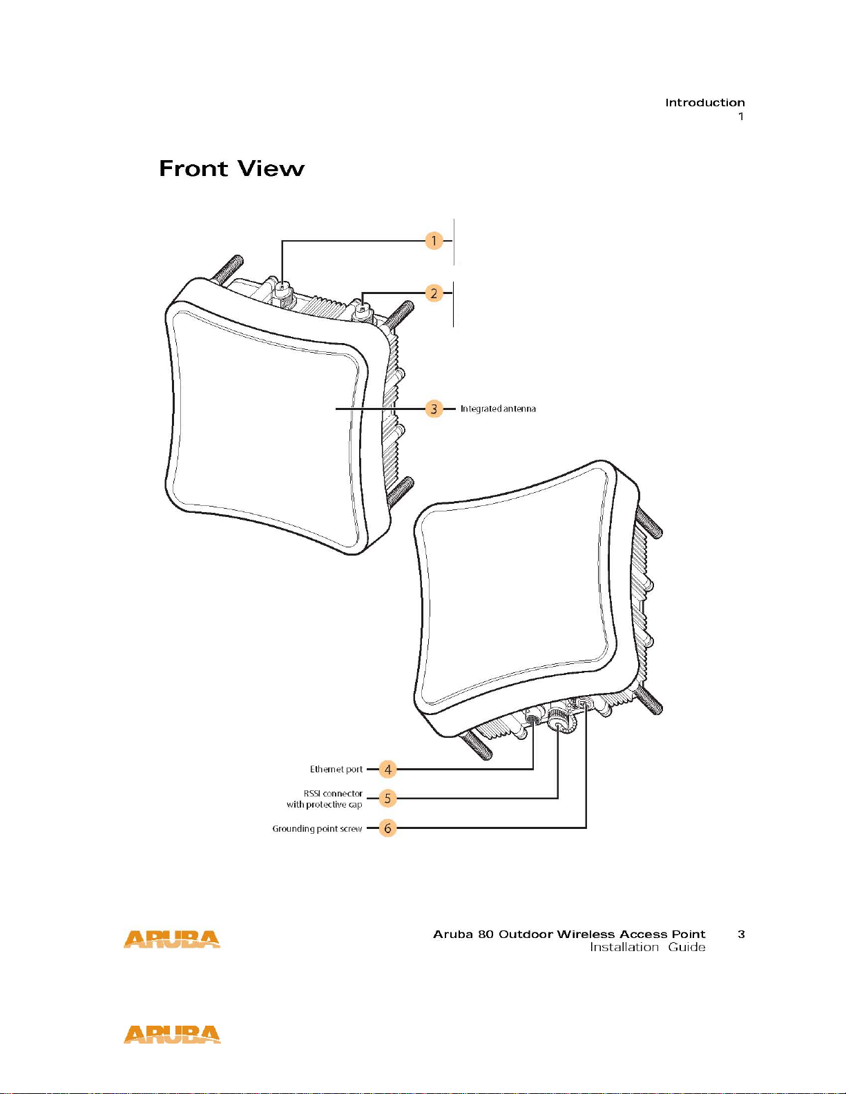
Front View. . . . . . . . . . . . . . . . . . . . . . . . . . . . . . . . . . . . . . . . . . 3
Rear View . . . . . . . . . . . . . . . . . . . . . . . . . . . . . . . . . . . . . . . . . . 5
The Aruba AP Setup Process . . . . . . . . . . . . . . . . . . . . . . . . . . . 6
System Configuration . . . . . . . . . . . . . . . . . . . . . . . . . . . . . . . . . . 6
Wall- and Pole-Mounting Bracket Kits . . . . . . . . . . . . . . . . 7
Aruba Discovery Protocol . . . . . . . . . . . . . . . . . . . . . . . . . . . . . . 9
Chapter 2 Provisioning Access Points. . . . . . . . . . . . . . . . . . . . . . .
9
Setting Aruba 80 Outdoor Wireless Access
Mounting the Aruba 80 Outdoor Wireless
AP Provisioning. . . . . . . . . . . . . . . . . . . . . . . . . . . . . . . . . . . . . . . 11
Point Parameters . . . . . . . . . . . . . . . . . . . . . . . . . . . . . . . . . . . . . 14
Access Point . . . . . . . . . . . . . . . . . . . . . . . . . . . . . . . . . . . . . . . . . 19
Chapter 3 AP Deployment . . . . . . . . . . . . . . . . . . . . . . . . . . . . . . . . . . . 19
Mounting the AP . . . . . . . . . . . . . . . . . . . . . . . . . . . . . . . . . . . . . 20
Using the Pole-Mounting Bracket . . . . . . . . . . . . . . . . . . . 20
Mount and Connect External Antennas . . . . . . . . . . . . . . . . 22
Connect Electrical Ground Wire to the AP . . . . . . . . . . . . . . 22
Connect Ethernet Cable to the AP . . . . . . . . . . . . . . . . . . . . . 22
Connect the Power Injector. . . . . . . . . . . . . . . . . . . . . . . . . . . . 23
Orient the Antennas. . . . . . . . . . . . . . . . . . . . . . . . . . . . . . . . . . . 24
Accessing the AP Support Prompt . . . . . . . . . . . . . . . . . . . . . 25
Remote Telnet Connection . . . . . . . . . . . . . . . . . . . . . . . . . 25
Appendix A Troubleshooting. . . . . . . . . . . . . . . . . . . . . . . . . . . . . . . . . . . 25
AP Support . . . . . . . . . . . . . . . . . . . . . . . . . . . . . . . . . . . . . . . . . . . 26
Access Levels . . . . . . . . . . . . . . . . . . . . . . . . . . . . . . . . . . . . . 26
User Commands . . . . . . . . . . . . . . . . . . . . . . . . . . . . . . . . . . . 26
Page 4

Privileged Commands . . . . . . . . . . . . . . . . . . . . . . . . . . . . . . 26
Aruba 80 8-Pin DIN Ethernet Connector Pinout . . . . . . . . . 27
Aruba 80 8-Pin DIN to RJ-45 Cable Wiring. . . . . . . . . . . . . . 27
Appendix B Port Specifications . . . . . . . . . . . . . . . . . . . . . . . . . . . . . . . 27
Aruba 80 Power over Ethernet Injector Module
10/100BASE-TX Pin Assignments. . . . . . . . . . . . . . . . . . . . . . 28
Straight-Through Wiring . . . . . . . . . . . . . . . . . . . . . . . . . . . . . . . 29
Crossover Wiring. . . . . . . . . . . . . . . . . . . . . . . . . . . . . . . . . . . . . . 29
Appendix C Product Specifications . . . . . . . . . . . . . . . . . . . . . . . . . . . 31
Compliance . . . . . . . . . . . . . . . . . . . . . . . . . . . . . . . . . . . . . . . . . . . 31
Certifications . . . . . . . . . . . . . . . . . . . . . . . . . . . . . . . . . . . . . . . . . 33
Product Features . . . . . . . . . . . . . . . . . . . . . . . . . . . . . . . . . . . . . . 34
Ethernet Compatibility . . . . . . . . . . . . . . . . . . . . . . . . . . . . . . 34
Radio Characteristics . . . . . . . . . . . . . . . . . . . . . . . . . . . . . . . 34
Power Over Ethernet . . . . . . . . . . . . . . . . . . . . . . . . . . . . . . . 35
Aruba 80 Detachable Antennas . . . . . . . . . . . . . . . . . . . . . . . . 42
Related Documents . . . . . . . . . . . . . . . . . . . . . . . . . . . . . . . . . . . 43
Contacting Aruba Wireless Networks . . . . . . . . . . . . . . . . . .
44
Page 5
Package Checklist
Package Contents
The Aruba 80 Outdoor Wireless Access Point package includes:
One Aruba 80 Outdoor Wireless Access Point (Models AP-80MB or AP-80SB)
Pole / Mast Mounting Hardware
Installation Guide (this manual)
Inform your supplier if there are any incorrect, missing or damaged parts. If possible, retain the
carton, including the original packing materials. Use them to repack the product in case there is a
need to return it.
Optional Items
The following optional items can also be ordered for the Aruba 80 Outdoor Wireless Access Point:
Detachable antennas (see Table C-3, “Detachable Antenn as,” on pag e 42) Aruba 80 AC Power Adapter
Kit (TX) – Indoor (AP-AC-80-1)
Indoor Use Only Auto-sensing 110/240VAC to 48VDC Power over Ethernet Injector suitable for
use with all Aruba AP-80 Series Wireless Access Points.
100 foot Outdoor Ethernet cable (8Pin DIN to 10/100Base-T RJ-45).
Aruba Outdoor Antenna Cable Extension – 10’ (AP-CBL-1)
10’ long low-loss LMR 400 antenna extension cable for use with AP-80 Outdoor Access Points,
interfaces AP-80 N-Type Female interface to N-Type Male on antenna.
Aruba Antenna Lightning Arrester N-Type (AP-LAR-1)
The Lightning Surge Arrester for the AP-80 Series Access Points is a single, In-line lightning arrester
with N-type Male to N-type Female interface. Supports RF frequency pass through of 2Ghz – 6Ghz.
Check with your Aruba sales representative for the availability of optional items.
Page 6

Overview
The Aruba 80 Outdoor Wireless Access Point is part of a comprehensive wireless network solution. The device
works in conjunction with the Aruba Mobility Controller and can act as a wireless access point or air monitor.
As a wireless Access Point (AP), the Aruba 80 Outdoor Wireless Access Point (also referred to as the Aruba 80)
provides transparent, secure, high-speed data communications between wireless network devices (fixed,
portable, or mobile computers with IEEE 802.11a (country regulatory domain permitting) or IEEE 802.11b/g
wireless adapters) and the wired LAN.
As a wireless Air Monitor (AM), a feature unique to Aruba products, the Aruba 80 Outdoor Wireless Access Point
enhances wireless networks by collecting statistics, monitoring traffic, detecting intrusions, enforcing security
policies, balancing wireless traffic load, self-healing coverage gaps, and more.
OTE—Installing the Aruba 80 requires setting the antenna power, which requires
N
professional training. The Aruba 80 installer must be trained to perform this
configuration.
Page 7
Model 80SB
2.4GHz, N-Type, Female
Model 80MB
5 GHz, N-Type, Female
Model 80SB
2.4GHz, N-Type, Female
Model 80MB
2.4 GHz, N-Type, Female
IGURE 1-1 Aruba 80 Outdoor Wireless Access Point Front View
F
Page 8

External Internal Antenna (2.4 GHz) Connector
For AP-80SB: 2.4 GHz, N-Type, Female connector
For AP-80MB: 5 GHz, N-Type, Female connector
External Internal Antenna (2.4 GHz) Connector
For AP-80SB: 2.4 GHz, N-Type, Female connector
For AP-80MB: 2.4 GHz, N-Type, Female connector
Internal 2.5 GHz 17.0 dBi, Directional Antenna (AP-80SB only)
FE Port
The wireless Access Point has one 10BASE-T/100BASE-TX 8-pin DIN port that connects to the power
injector module using the included Ethernet cable. The Ethernet port connection provides power to the
wireless Access Point as well as a data link to the local network.
The wireless Access Point appears as an Ethernet node and performs a bridging function by moving packets
from the wired LAN to the remote end of the wireless Access Point link.
OTE: The power injector module does not support Power over Ethernet (PoE) based on the IEEE 802.3af
N
standard. The wireless Access Point unit must always be powered on by being connected to the
power injector module.
RSSI Connector
Not used.
Grounding Screw
Even though the wireless Access Point includes its own built-in lightning protection, it is important
that the unit is properly connected to ground. A grounding screw is provided for attaching a ground
wire to the unit.
OTE: The Aruba 80 requires lightening protection. Aruba recommends the use of lightening arresters.
N
Failure to provide protection from lightening strikes will void the warranty for this product.
See Appendix B for port and cable specifications.
Page 9

Rear View
Mounting bolts
Vertical mounting indicator
This is the vertical integrated antenna polarization indicator.
Horizontal mounting indicator.
This is the horizontal integrated antenna polarization indicator.
See Appendix B for port and cable specifications.
Page 10
The Aruba AP Setup Process
Setting up an Aruba AP typically consists of four stages:
1 WLAN Planning—The administrator determines how many Aruba APs will be needed for their wireless network
strategy and where they will be deployed. This can be easily accomplished using Aruba’s automated RF Plan
site-survey software (available separately).
2 AP Provisioning—Provisioning provides each Aruba AP with initial settings that allow it to locate the host Aruba
Mobility Controller. Depending on the network topology and services, AP provisioning can be performed
manually for each AP or plug-and-play for batches of APs.
AP provisioning is discussed in “Provisioning Access Points”.
3 AP Deployment—Once provisioned, each AP can be physically installed at its intended place of operation.
AP deployment is covered in “Hardware Installation”.
4 AP Configuration—The administrator defines the operational behavior for each Aruba AP, such as RF
characteristics and security features.
For AP configuration information, refer to the ArubaOS Applications Configuration Guide.
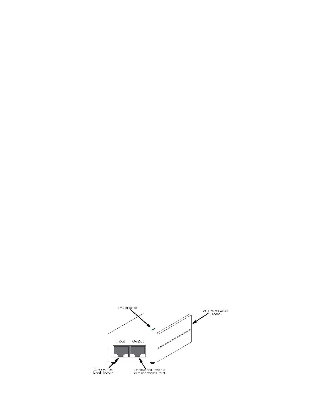
System Configuration
The wireless Access Point receives power through a special cable (sold separately) to connect to the
non-802.3af-complaint Power over Ethernet injector module. The power injector module provides two
RJ-45 Ethernet ports, one for connecting to the wireless Access Point (Output), and the other for
connecting to a local LAN switch (Input).
At each location where a unit is installed, it must be connected to the local network using the
power injector module.
The Power over Ethernet injector module port uses an MDI (i.e., internal straight-through) pin
configuration. You can therefore use straight-through twisted-pair cable to connect this port to most
network interconnection devices such as a switch or router that provide MDI-X ports. However, when
connecting the access point to a workstation or other device that does not have MDI-X ports, you must
use crossover twisted-pair cable.
Page 11

The wireless Access Point does not have a power switch. It is powered on when its Ethernet port is connected
to the power injector module, and the power injector module is connected to an AC power source. The power
injector includes one LED indicator that turns on when AC power is applied.
The power injector module automatically adjusts to any AC voltage between 100-240 volts at 50 or 60
Hz. No voltage range settings are required.
W
ARNING: The power injector module is designed for outdoor use only. Never mount the power injector
outside with the wireless Access Point unit.
Wall- and Pole-Mounting Bracket Kits
The wireless Access Point includes bracket kits that can be used to mount the Access Point to a wall, pole,
radio mast, or part of a tower structure.
Page 12

Page 13
The wireless bridge offers a variety of management options, including a web-based interface, a command line
interface (CLI), or using SNMP management software.
Most initial configuration steps can be made through the web browser interface using the Setup Wizard.
However, for units that do not have a preset country code, you must first set the country code using the CLI.
Note: Units sold in some countries are not configured with a specific country code. You must use the CLI to
set the country code and enable wireless operation.
The wireless bridge uses the IP address 192.168.1.1 by default. If this address is not compatible with your
network, you can first perform initial configuration using a PC that has IP settings compatible with this subnet
(for example, 192.168.1.2) and connecting it directly to the wireless bridge. When the basic configuration is
completed, you can set new IP settings for the wireless bridge before connecting it to your network.
Initial Setup through the CLI
The wireless bridge provides access to the CLI through a Telnet connection. You can open a Telnet session by
performing these steps:
1. From the host computer, enter the Telnet command and the IP address of the wireless bridge unit
(default 192.168.1.1).
2. At the prompt, enter “admin” for the user name.
3. The default password is null, so just press [Enter] at the password prompt.
The CLI will display the “Aruba Networks AP-80MB#” prompt to show that you are using executive access
mode (i.e., Exec).
Username: admin
Password:
Aruba Networks AP-80MB#
Page 14
Initial Configuration Steps
Setting the Country Code – Regulations for wireless products differ from country to country. Setting the
country code restricts the wireless bridge to use only the radio channels and power settings permitted in the
specified country of operation. If the wireless bridge unit is shipped with a preset country code, you are not
permitted to
country code to the country of operation.
At the Exec prompt, type “country ?” to display the list of country codes. Check the code for your country, then
enter the country command again followed by your country code (e.g., IE for Ireland).
Aruba Networks AP-80MB#country ie
Aruba Networks AP-80MB#
Setting the IP Address – By default, the wireless bridge is configured with the IP address 192.168.1.1. You
may also use the CLI to assign an IP address that is compatible with your network.
Type “configure” to enter configuration mode, then type “interface ethernet” to access the Ethernet
interface-configuration mode.
Aruba Networks AP-80MB #configure
Aruba Networks AP-80MB (config)#interface ethernet
Aruba Networks AP-80MB (config-if)#
Type “ip address ip-address netmask gateway,” where “ip-address” is the wireless bridge’s IP address,
“netmask” is the network mask for the network, and “gateway” is the default gateway router. Check with your
system administrator to obtain an IP address that is compatible with your network.
Aruba Networks AP-80MB (if-ethernet)#ip address 192.168.2.2 255.255.255.0 192.168.2.254
Aruba Networks AP-80MB (if-ethernet)#
change it, as required by country regulations. If the unit is set to the default “99,” you must set the
After configuring the wireless bridge’s IP parameters, you can access the management interface from
anywhere within the attached network. The command line interface can also be accessed using Telnet from
any computer attached to the network.
Page 15

Using the Web-based Management Setup Wizard
There are only a few basic steps you need to complete to set up the wireless bridge for your network. The
Setup Wizard takes you through configuration procedures for the radio channel selection, IP configuration,
and basic WEP encryption for wireless security.
The wireless bridge can be managed by any computer using a web browser (Internet Explorer 5.0 or above, or
Netscape Navigator 6.2 or above). Enter the IP configured for the unit or the default IP address:
http://192.168.1.1
Logging In – Enter the default username “admin” and click LOGIN (there is no default password). For
information on configuring a user name and password.
The home page displays the Main Menu.
Launching the Setup Wizard – To perform initial configuration, click Setup Wizard on the home page, then
click on the [Next] button to start the process.
Page 16

1. Service Set ID – Enter the service set identifier in the SSID box which all wireless clients must use to
associate with the access point. The SSID is case sensitive and can consist of up to 32 alphanumeric
characters (Default: DualBandOutdoor).
2. Radio Channel – You must enable radio communications for the 802.11a radio and set the operating
channel.
Page 17

802.11a
Turbo Mode – If you select Enable, the wireless bridge will operate in turbo mode with a data rate of up
to 108 Mbps. Normal mode supports 13 channels, Turbo mode supports only 5 channels. (Default:
Disable)
802.11a Radio Channel – Set the operating radio channel number. (Default: 56ch, 5.280 GHz)
Auto Channel Select – Select Enable for automatic radio channel detection. (Default: Disable)
802.11b/g
802.11g Radio Channel: Set the operating radio channel number. (Range 1-11; Default: 1)
Available channel settings are limited by local regulations which determine which channels are available.
3. IP Configuration – Either enable or disable (Dynamic Host Configuration Protocol (DHCP) for
automatic IP configuration. If you disable DHCP, then manually enter the IP address and subnet
mask. If a management station exists on another network segment, then you must enter the IP
address for a gateway that can route traffic between these segments. Then enter the IP address for
the primary and secondary Domain Name Servers (DNS) servers to be used for host-name to IP
address resolution.
DHCP Client – With DHCP Client enabled, the IP address, subnet mask and default gateway can be
dynamically assigned to the access point by the network DHCP server. (Default: Disable)
If there is no DHCP server on your network, then the access point will automatically start up with its default IP
address, 192.168.1.1.
4. WDS Settings – To set up a wireless bridge link, you must configure the WDS forwarding table by
specifying the wireless MAC address of the bridge to which you want to forward traffic. For a Slave
bridge unit, you need to specify the MAC address of the wireless bridge unit at the opposite end of the
link. For a Master bridge unit, you need to specify the MAC addresses of all the Slave bridge units in
the network.
Page 18

Set the distance value used to adjust timeout values to take into account transmit delays due to link
distances in the wireless bridge network. For a point-to-point link, specify the approximate distance
between the two bridges. For a point-to-multipoint network, specify the distance of the Slave bridge
farthest from the Master bridge.
5. Security – Set the Authentication Type to “Open System” to allow open access without
authentication, or “Shared Key” to require authentication based on a shared key. Enable Wired
Equivalent Privacy (WEP) to encrypt data transmissions.
Authentication Type – Use “Open System” to allow open access to all wireless clients without performing
authentication, or “Shared Key” to perform authentication based on a shared key that has been distributed to
all stations. (Default: Open System)
WEP – Wired Equivalent Privacy is used to encrypt transmissions passing between wireless clients and the
access point. (Default: Disabled)
Shared Key Setup – If you select “Shared Key” authentication type or enable WEP, then you also need to
configure the shared key by selecting 64-bit or 128-bit key type, and entering a hexadecimal or ASCII string of
the appropriate length. The key can be entered as alphanumeric characters or hexadecimal (0~9, A~F, e.g.,
D7 0A 9C 7F E5). (Default: 128 bit, hexadecimal key type)
64-Bit Manual Entry: The key can contain 10 hexadecimal digits, or 5 alphanumeric characters.
128-Bit Manual Entry: The key can contain 26 hexadecimal digits or 13 alphanumeric characters.
All wireless devices must be configured with the same Key ID values to communicate with the access point.
6. Click Finish.
Page 19

7. Click the OK button to restart the access point.
Page 20

Page 21

Mounting the Aruba 80 Outdoor Wireless Access Point
WARNING: The installation of Outdoor rated Access Points, antennas or ancillary
The Aruba 80 Outdoor Wireless Access Point may be deployed outdoors, exposed to the elements (extreme
sunshine, rain, snow - hot and cold climates) and mounted on a wall, pole or mast.
The Aruba 80 Indoor rated Power over Ethernet injector (model AP-AC-80-1) must be deployed indoors, or
within an enclosure protecting it from the elements.
The Aruba 80 Outdoor Wireless Access Point is supplied complete with its own mounting hardware kit for
attaching the unit to a 1.5” to 2” diameter steel pole or tube or as part of a radio mast or tower structure.
Physical installation of the Aruba 80 Outdoor Wireless Access Point involves the following steps:
1. Mount the unit on a wall, pole, mast, or tower using the mounting bracket.
2. Mount external antennas on the same supporting structure as the Access Point and connect them to the
Access Point unit.
Caution: NOTE: the use of lightning arrester units, in-line or mast mounted, with the N-Type antenna interface is highly
recommended and if not used may void product warranty.
Caution: Be sure that grounding is available and that it meets local and national electrical codes. For additional lightning
protection, use lightning rods, lightning arrestors, or surge suppressors.
3. Connect the grounding wire to the unit.
4. Connect the Ethernet cable to the unit.
5. Connect the power injector to the Ethernet cable, a local LAN network point and an AC power source.
6. Orient the antennas.
equipment should only be performed by trained personnel. Do NOT attempt to
install an Access Point on an elevated building, mast or pole by yourself or without
the use of the appropriate safety equipment
Page 22

Mounting the AP
A
Using the Pole-Mounting Bracket
Perform the following steps to mount the unit to a 1.5 to 2 inch diameter steel pole or tube using the
mounting bracket:
1. Always attach the bracket to a pole with the open end of the mounting grooves facing up.
2. Place the U-shaped part of the bracket around the pole and tighten the securing nut just enough to hold the
bracket to the pole. (The bracket may need to be rotated around the pole during the alignment process.)
ttach bracket to pole with
mounting grooves facing up
3. Use the included nuts to tightly secure the wireless Access Point to the bracket. Be sure to take account of the
antenna polarization direction; both antennas in a link must be mounted with the same polarization.
Page 23

Mounting on Larger Diameter Poles
In addition, there is a method for attaching the pole-mounting bracket to a pole that is 2 to 5 inches in diameter
using an adjustable steel band clamp (not included in the kit). A steel band clamp up to 0.5 inch (1.27 cm) wide
can be threaded through the main part of the bracket to secure it to a larger diameter pole without using the
U-shaped part of the bracket. This method is illustrated in the following figure.
4.
Page 24

Mount and Connect External Antennas
Physically mount detachable antennas in their desired location, preferably to the same supporting
structure as the Access Point, within 3 m (10 ft) distance, using the bracket supplied in the antenna.
Connect the antenna to the Access Point’s N-type Female connector using the RF coaxial cable
provided with the antenna.
Apply weatherproofing tape to the antenna connectors to help prevent water entering the
connectors.
When no antenna is connected to the N-Type interface, the waterproof interface boot should remain
installed to protect the interface from the elements.
Connect Electrical Ground Wire to the AP
Attach an electrical safety grounding wire to the electrical ground point on the access point.
Caution: Be sure that grounding is available and that it meets local and national electrical codes. For
additional lightning protection, use lightning rods, lightning arrestors, or surge suppressors.
Connect Ethernet Cable to the AP
1. Attach the Ethernet cable to the Ethernet port on the wireless Access Point.
NOTE: The Ethernet cable included with package (AP-AC-80-1, indoor Power Injector) is 30 m
(100 ft) long. To wire a longer cable (maximum 100 m, 325 ft), use the connector pinout
information in Appendix B.
1. 2. For extra protection against rain or moisture, apply weatherproofing tape (not included) around
the Ethernet connector.
2. 3. Be sure to ground the unit with an appropriate grounding wire (not included) by attaching it to the
grounding screw on the unit.
Caution: Be sure that grounding is available and that it meets local and national electrical codes.
For additional lightning protection, use lightning rods, lightning arrestors, or surge
suppressors.
Page 25

Connect the Power Injector
To connect the Aruba 80 Outdoor Wireless Access Point to a power source:
Caution: The wireless outdoor Access Point’s Ethernet port does not support Power over Ethernet (PoE) based on
1. 1. Connect the Ethernet cable from the wireless Access Point to the RJ-45 port labeled “Output” on
the power injector.
2. 2. Connect a straight-through unshielded twisted-pair (UTP) cable from a local LAN switch to the
RJ-45 port labeled “Input” on the power injector. Use Category 5 or better UTP cable for 10/100BASE-TX
connections.
the IEEE 802.3af standard. Do not try to power the unit by connecting it directly to a network switch that
provides IEEE 802.3af PoE due to the AP’s maximum power draw requirement of 30 Watts. Always
connect the unit to the correct Power over Ethernet injector module (sold separately).
NOTE: The RJ-45 port on the power injector is an MDI port. If connecting directly to a
computer for testing the link, use a crossover cable.
wireless Access
Point
1. 3. Insert the power cable plug directly into the standard AC receptacle on the power injector.
2. 4. Plug the other end of the power cable into a grounded, 3-pin socket, AC power source.
NOTE: For International use, you may need to change the AC line cord. You must use a lin e cord set that
has been approved for the receptacle type in your country.
5. Check the LED on top of the power injector to be sure that power is being supplied to the wireless Access Point
through the Ethernet connection.
Page 26

Orient the Antennas
After the Aruba 80 Outdoor Wireless Access Point units have been mounted, connected, and their
radios are operating, the antennas must be accurately aligned to ensure optimum performance on the
Access Point links.
Page 27

Check the following items before you contact local Technical Support.
1. If wireless bridge units do not associate with each other, check the following:
• Check the power injector LED for each bridge unit to be sure that power is being supplied
• Be sure that antennas in the link are properly aligned.
• Be sure that channel settings match on all bridges
• If encryption is enabled, ensure that all bridge links are configured with the same encryption keys.
2. If you experience poor performance (high packet loss rate) over the wireless bridge link:
• Check that the range of the link is within the limits for the antennas used.
• Be sure that antennas in the link are properly aligned.
• Check that there is an unobstructed radio line-of-sight between the antennas.
• Be sure there is no interference from other radio sources. Try setting the bridge link to another radio
channel.
• Be sure there is no other radio transmitter too close to either antenna. If necessary, move the
antennas to another location.
3. If the wireless bridge cannot be configured using Telnet, a web browser, or SNMP software:
• Be sure to have configured the wireless bridge with a valid IP address, subnet mask and default
gateway.
• Check that you have a valid network connection to the wireless bridge and that the Ethernet port or
the wireless interface has not been disabled.
• If you are connecting to the wireless bridge through the wired Ethernet interface, check the network
cabling between the management station and the wireless bridge.
• If you cannot connect using Telnet, you may have exceeded the maximum number of concurrent
Telnet sessions permitted (i.e, four sessions). Try connecting again at a later time.
4. If all other recovery measures fail, and the wireless bridge is still not functioning properly, take any of these
steps:
• Reset the wireless bridge’s hardware using the CLI, web interface, or through a power reset.
• Reset the wireless bridge to its default configuration.
5. If you forgot or lost the password:
• Contact Technical Support.
Page 28

Page 29

Aruba 80 8-Pin DIN Ethernet Connector Pinout
The Ethernet cable from the power injector connects to an 8-pin DIN connector on the Aruba 80 outdoor
wireless Access Point. This connector is described in the following figure and table.
Pin Signal Name
1 Transmit Data plus (TD+)
2 Transmit Data minus (TD)
3 Receive Data plus (RD+)
4 +48 VDC power
5 +48 VDC power
6 Receive Data minus (RD-)
7 Return power
8 Return power
8-Pin DIN Ethernet Port Pinout
Note: The “+” and “-” signs represent the polarity of the wires that make up each wire pair.
Aruba 80 8-Pin DIN to RJ-45 Cable Wiring
To construct an extended Ethernet cable to connect from the power injector’s RJ-45 Output port to the
wireless Access Point’s 8-pin DIN connector, follow the wiring diagram below. Use Category 5 or better
UTP or STP cable, maximum length 100 m (328 ft), and be sure to connect all four wire pairs.
OTE: To construct a reliable Ethernet cable, always use the proper tools or ask a professional
N
cable supplier to construct the cable.
Page 30

Aruba 80 Power over Ethernet Injector Module
10/100BASE-TX Pin Assignments
Use unshielded twisted-pair (UTP) or shielded twisted-pair (STP) cable for RJ-45 connections: 100-ohm
Category 3 or better cable for 10 Mbps connections, or 100-ohm Category 5 or better cable for 100
Mbps connections. Also be sure that the length of any twisted-pair connection does not exceed 100
meters (328 feet).
The RJ-45 Input port on the power injector is wired with MDI pinouts. This means that you must use
crossover cables for connections to PCs or servers, and straight-through cable for connections to
switches or hubs. However, when connecting to devices that support automatic MDI/MDI-X pinout
configuration, you can use either straight-through or crossover cable.
10/100BASE-TX MDI and MDI -X Port Pinouts
MDI-X Signal Name Pin 1
Receive Data plus (RD+) Transmit Data plus (TD+)
Receive Data minus (RD-) 2 3
Transmit Data plus (TD+) Receive Data plus (RD+)
Transmit Data minus (TD-) 6 4,5,7,8 Receive Data minus (RD-)
Not used Not used
Note: The “+” and “-” signs represent the polarity of the wires that make up each wire pair.
MDI Signal Name
Transmit Data minus (TD-)
Page 31

Straight-Through Wiring
Because the 10/100 Mbps Input port on the power injector uses an MDI pin configuration, you must use
“straight-through” cable for network connections to hubs or switches that only have MDI-X ports. However, if
the device to which you are connecting supports automatic MDI/MDI-X operation, you can use either
“straight-through” or “crossover” cable.
EIA/TIA 568B RJ-45 Wiring Standard
10/100BASE-TX Straight-through Cable
Crossover Wiring
Because the 10/100 Mbps port on the power injector uses an MDI pin configuration, you must use
“crossover” cable for network connections to PCs, servers or other end nodes that only have MDI ports.
However, if the device to which you are connecting supports automatic MDI/MDI-X operation, you can
use either “straight-through” or “crossover” cable.
EIA/TIA 568B RJ-45 Wiring Standard
10/100BASE-TX Crossover Cable
Page 32

Page 33

Compliance
FCC - Class B
This equipment has been tested and found to comply with the limits for a Class B digital device,
pursuant to Part 15 of the FCC Rules. These limits are designed to provide reasonable protection
against harmful interference when the equipment is operated in a commercial environment. This
equipment generates, uses, and can radiate radio frequency energy and, if not installed and used in
accordance with the instruction manual, may cause harmful interference to radio communications.
Operation of this equipment in a residential area is likely to cause harmful interference in which case the
user will be required to correct the interference at their own expense.
Any changes or modifications not expressly approved by the party responsible for compliance could
void the user’s authority to operate this equipment.
This product complies with Part 15 of the FCC Rules. Operation is subject to the following two
conditions: (1) this device may not cause harmful interference, and
(2) this device must accept any interference received, including interference that may cause undesired
operation.
CAUTION STATEMENT: FCC RF Radiation Exposure Statement
This equipment complies with FCC RF radiation exposure limits set forth for fixed outdoor use only. This
equipment should be installed and operated with a minimum distance of 15.2 inches (38.5 centimeters)
between the radiator and your body for 2.4 GHz and 5 Ghz operations. This transmitter must not be
co-located or operating in conjunction with any other antenna or transmitter.
Radio Frequency Interference Requirements
Operations in the 5.15-5.25GHz band are restricted to indoor usage only.
In 5.15-5.25GHz band, the FCC requires this product to be used indoors to reduce the
potential for harmful interference to co-channel Mobile Satellite systems. High power radars
are allocated as primary users of the 5.25 to 5.35 GHz and 5.65 to 5.85 GHz bands. These
radar stations can cause interference with and/or damage this device.
Page 34

Industry Canada - Class A
This digital apparatus does not exceed the Class A limits for radio noise emissions from
digital apparatus as set out in the interference-causing equipment standard entitled “Digital
Apparatus,” ICES-003 of the Department of Communications.
Cet appareil numérique respecte les limites de bruits radioélectriques applicables aux
appareils numériques de Classe A prescrites dans la norme sur le matériel brouilleur:
“Appareils Numériques,” NMB-003 édictée par le ministère des Communications.
This product complies with IC RSS 210 Rules. Operation is subject to the following two
conditions: (1) this device may not cause harmful interference, and
(2) this device must accept any interference received, including interference that may cause undesired
operation.
To reduce potential radio interference to other users, the antenna type and its gain
should be so chosen that the equivalent isotropically radiated power (EIRP) is not more
than that required for successful communication".
"The installer of this radio equipment must ensure that the antenna is
located or pointed such that it does not emit RF field in excess of Health
Canada limits for the general population; consult Safety Code 6, obtainable
from Health Canada
'
s website www.hc-sc.gc.ca/rpb"
VCCI - Class A
CE - Class A
Warning—This is a Class A product. In a domestic environment, this product may cause radio
interference in which case the user may be required to take adequate measures.
EU - Class A
This product complies with EN5022 Class A and EN5024 standards.
Page 35

Underwriter Labs
These products have been Listed and tested for fire resistant and low-smoke-producing characteristics, and
are suitable for use in environmental air space, such as above suspended ceilings, in accordance with Section
300-22(C) of the National Electrical Code, and Sections 2-128, 12-010(3) and 12-100 of the Canadian
Electrical Code, Part 1, CSA C22.1.
Peut être utilisé dans des gaines transportant de l’air traité, conformément à la section 300-22(c) du National
Electrical Code et aux articles 2-128, 12-010(3) et 12-100 du Code Canadien de l’électricité, Première partie,
CSA C22.1.
Certifications
Item Measurement
Electromagnetic Compatibility
FCC Part 15 subpart C (15.247/15.407
RSS 210 (CAN)
TELEC ARIB STD-T66
EN 61000-4-2, EN 61000-4-3, EN 61000-4-4, EN 61000-4-5, EN 61000-4-6, EN 61000-4-11
73/23/ECC
The CE approval mark on back of the product indicates that it meets European Directives
73/23/EEC and 89/336/EEC R&TTE Directive: ETS EN 300 328, ETS EN 301 489, ETS EN 301 893
RFS 29 (NZ)
Safety UL Listed (UL60950) UL Listed (Canadian Electrical Code/CSA 22.2 No. 60950)
EN60950 / IEC60950 National Electrical Code Section 300-22(C) Canadian
Electrical Code, Part 1, CSA C22.1 Sections 2-128, 12-010(3), and 12-100
Page 36

Product Features
Wireless dual-band transceiver
Various antenna options (see Table C-3)
Aruba AP-80SB features an integrated 17dBi 5 GHz directional antenna
Protocol-independent networking functionality
Supports IEEE 802.11a or IEEE 802.11b/g operation as an AP
Supports IEEE 802.11a and IEEE 802.11b/g operation as an AM
Seamless connectivity to wired LANs augment existing networks quickly and
The Aruba 80 Outdoor Wireless Access Point attaches to 10/100 Mbps Ethernet (FE) LAN segments that
utilize 10Base-T/100Base-TX (twisted-pair) wiring. The device appears as an Ethernet node and performs a
routing function by moving packets between the wired LAN and remote workstations on the wireless
infrastructure.
Radio Characteristics
The Aruba 80 Outdoor Wireless Access Point can be configured to support IEEE 802.11a or IEEE 802.11b/g
operation as an AP, and supports both IEEE 802.11a and IEEE 802.11b/g operation as an AM:
802.11a provides a high data rate and reliable wireless connectivity
easily
Can be centrally managed, configured, and upgraded through the Switch
name to take advantage of network changes and security improvements
Ethernet Compatibility
802.11a operation uses a radio modulation technique known as Orthogonal
Frequency Division Multiplexing (OFDM), and a shared collision domain
(CSMA/CA). It operates in the 5 Ghz Unlicensed National Information
Infrastructure (UNII) band. Data is transmitted over a half-duplex radio channel
operating at up to 54 Megabits per second (Mbps).
802.11b provides an alternative to wired LANs that can dramatically cut costs
802.11b operation uses the IEEE 802.11 High-Rate Direct Sequence (HRDS)
specification, and a shared collision domain (CSMA/CA). It operates in the 2.4
Ghz Industrial/Scientific/Medical (ISM) band. The ISM band is available
worldwide for unlicensed use. Data is transmitted at speeds of up to 11
Mbps.
802.11g provides a high data rate and is backwards compatible with 802.11b.
802.11g operation uses ODFM and a shared collision domain (CSMA/CA). It
operates in the 2.4 Ghz Industrial/Scientific/Medical (ISM) band. The ISM
band is available worldwide for unlicensed use. Data is transmitted at speeds
of up to 54 Mbps.
Product Specifications
Page 37

Power Over Ethernet
The Aruba 80 Outdoor Wireless Access Point supports non-standard Power Over Ethernet (POE) using the
Aruba 80 POE Injector Module (sold separately), due to its 30W power draw requirement.
Page 38

TABLE C-1 Aruba 80 802.11 Specifications
Description 802.11a 802.11b 802.11g
Integral Model AP-80SB only:
Antenna
External Antenna
Frequency 5.150 ~ 5.250 2.4 ~ 2.483 2.412 ~ 2.462
Band Ghz (low band) 4 channels Ghz (US, Canada & Ghz (US, Canada)
5 Ghz 17.0 dBi
Aruba offer a wide variety of detachable antenna types suitable for use with the AP
80. Please contact your local sales representative for details
Radio
Technology
5.250 ~ 5.700
Ghz (ETSI) 11 channels 2.4 ~ 2.497 Ghz
5.500~ 5.825 Ghz (high
band) 4 channels 5.725
~ 5.825 Ghz (high band) 4
channels
Orthogonal Frequency
Division
Multiplexing (OFDM) (DSSS) Division
Modulation BPSK, QPSK, CCK, BPSK, QPSK CCK, BPSK,
Type 16-QAM, 64-QAM
Transmit Configurable by Configurable by Configurable by
Power
system system system
administrator/ professional
installer
ETSI)
(Japan)
Complete country list
available at http://
www.arubanetwo rks.
com/products/aps /
certification
Direct Sequence Spread
Spectrum
administrator/
professional
installer
2.412 ~ 2.472
Ghz (ETSI) 2.412 ~
2.484
Ghz (Japan) Complete
country list available at
http:// www.arubanetw
orks. com/products/ap
s/ certification
Orthogonal Frequency
Multiplexing (OFDM)
QPSK, 16-QAM,
64-QAM
administrator
Page 39

TABLE C-1 Aruba 80 802.11 Specifications (Continued)
Description 802.11a 802.11b 802.11g
Media CSMA/CA with ACK CSMA/CA with CSMA/CA with
Access
Control
ACK ACK
Operating
Channels
Data Rates 6, 9, 12, 18, 24, 36, 1, 2, 5.5, 11 Mbps 6, 9, 12, 18, 24,
US & Canada: 8
external
antenna 12 internal
antenna Japan: 14 Japan: 13
ETSI: 11 Japan:
Disabled Complete country
list available at http://
www.arubanetworks.com/ rks.com/products/ certification
products/aps/certification aps/
48, 54 Mbps per per channel 36, 48, 54 Mbps
channel
US & Canada: 11 US & Canada: 11
ETSI: 13 ETSI: 13
Complete country
list available at
www.arubanetwo
http://
Complete country list
available at
www.arubanetworks.
com/products/aps/
http://
certification
per channel
Page 40

TABLE C-2 Aruba 80 Characteristics
Description
Maximum Clients
Multi-mode Radio Band Selectable via software
Manageability:
64
Management of all 802.11 parameters as AP
Network-wide AP management via:
WEB GUI
SNMP Access point profiles
Management by:
Geographical location
BSSID
Radio type Encryption support (AP and Switch)
40-bit / 64-bit / 128-bit / 152-bit WEP, TKIP, AES, WPA
40bit / 64bit / 128bit / 152bit WEP, TKIP, AES, WPA,
Encryption Support (AP
and Mobility Controller)
Physical (HxWxD): 198 x 198 x 70mm (7.80 x 7.80 x 2.76 in.)
Part Numbers 64 AP-80MB
Weight 1.6 kilograms (3.53 pounds)
Aruba 80 Master Outdoor Wireless Access Point8
AP-80SB
Aruba 80 Slave Outdoor Wireless Access Point
Telnet
Page 41

TABLE C-2 Aruba 80 Characteristics (Continued)
Description
Interfaces
(Electrical):
AP-80MB & AP-80SB Common Interfaces
1 x 10/100 Base-TX (8-Pin DIN Connector)
auto-sensing Ethernet interface:
Auto-sensing MDI/MDX
PoE 48V DC / 1.2A power over Ethernet (not
compliant with 802.3af)
8-Pin DIN to RJ-45 CAT-5 Ethernet Cable
Supplied (30 m / 100 ft
1 x RSSI Low Voltage BNC Interface (not used)
1 x Electrical Ground Point with built-in lightening
arrester
AP-80MB Only Interfaces
1 x 2.4Ghz N-Type, Female, Detachable Antenna Interface
1 x 5Ghz N-Type, Female, Detachable Antenna Interface
AP-80SB-Only Interfaces
2 x 2.4Ghz N-Type, Female, Detachable Antenna
Interfaces (supports radio signal diversity)
Interfaces
(Mechanical):
4 x Mounting Bracket Hex Screw Mounting Points
Ruggedized wall, pole or mast mount hardware
provided (articulating in horizontal and vertical planes)
Visual Indicators
(LEDs)
Power Requirements AP-80MB and AP-80SB Power Draw: 48 VDC, 1.2 A, 30 W maximum
Ready -- Power on/off (provided on Power Injector)
AP-AC-80-1 Indoor-rated Power Injector Kit
Power Injector, auto-sensing 100-240V AC Input, 1.5A. Output 48 VDC, 1.2
A power over Ethernet (not compliant with 802.3af)
Page 42

TABLE C-2 Aruba 80 Characteristics (Continued)
Description
Output Power 100 mW maximum (or lower as configured on the
Environmental:
Standards
Compliance
Electromagnetic
Compliance
Aruba Mobility Controller to comply with local
regulatory requirements)
Temperature:
Operating: -30 to 55 oC (-22 to 131 oF)
Storage: -30 to 55oC (-22 to 131 oF)
Humidity:
Humidity 15% to 95% (non-condensing)
Survival Wind Speed: 201Km.hr (125 MPH)
Ethernet IEEE 802.3 / IEEE 802.3u
Wireless IEEE 802.11a/b/g
FCC DOC Part 15 Class B Digital
FCC Part 15 Class C 15.207/15.247
FCC Part 15 Class E 15.407
ICES-003 Class B
RSS 210 (CAN)
VCCI Class B
EN 61000-3, EN 61000-4-2, EN 61000-4-3, EN
61000-4-4
EN 61000-4-5, EN 61000-4-6, EN 61000-4-8, EN
61000-4-11
73/23/EEC and 89/336/EEC
EN 55022, EN55024 (89/336/EEC)
ETS 300 328 (89/336/EEC), ETS 301 489
(89/336/EEC)
ETS 301 893
AS/NZS 3548 Class B
AS/NZS 4771 C-tick
MIC Korea
Page 43

TABLE C-2 Aruba 80 Characteristics (Continued)
Description
Safety
cULus Listed Compliance
IEC 60950 CB Certificate and report UL Listed (Canadian Electrical
Code/CSA 22.2 No.
60950) EN60950 / IEC60950 National Electrical Code Section
300-22(C) Canadian Electrical Code, Part 1, CSA C22.1
Sections 2-128, 12-010(3), and 12-100 PSE Mar
Page 44

Aruba 80 Detachable Antennas
The follow detachable antennas are supported by the Aruba 80.
TABLE C-3 Detachable Antennas
Antenna Type Gain HPBW
*
Horizo
ntal
5 GHz
Omnidirectional
5 GHz
120-Degree
Sector
5 GHz
60-Degree
Sector
5 GHz
High-Gain
Panel
2.4 GHz
Omnidirectional
* Half-power beam width in degrees
8
1
4
1
7
2
3
8
360 12 Linear,
120 6 Linear,
60 6 Linear,
9 9 Linear
360 15 Linear,
HPBW
*
Vertic
al
Polarizati
on
vertical
vertical
vertical
vertical
Max
Range/Speed
2.6 km at6
Mbps
10.3 km at 6
Mbps
14 km at6
Mbps
24.4 km at 6
Mbps
7.6 km at6
Mbps
Page 45

Related Documents
The following items are part of the complete documentation for the Aruba system:
Aruba Quick Start Guide
Aruba 80 Wireless Access Point Installation and User Guide (this document)
Aruba Mobility Controller Installation Guide
ArubaOS Application Configuration Guide
ArubaOS Reference Guide
For the current versions o f these manuals, or to obtain the latest product release notes, vis it the
support section of our Web site.
Page 46

Contacting Aruba Wireless Networks
Web Site
Main Site http://www.arubanetworks.com Support http://www.arubanetworks.com/support
E-mail
Sales sales@arubanetworks.com
Support support@arubanetworks.com
Telephone Numbers
Main 408-227-4500
Fax 408-227-4550
Sales 408-754-1201
Support In the U.S.: 800-WI-FI-LAN (800-943-4526)
France: +33 (0) 170725559
UK: +44 (0) 2071275989
Germany: +49 (0) 69380977228
Other International: + 00 1 408-754-1200
1322 Crossman Avenue Sunnyvale, California 94089 Tel 408.227.4500 Fax 408.227.4550 Net
www.arubanetworks.com
Support: support@arubanetworks.com 1-800-WIFI-LAN (800 943-4526) 408 754-1200
 Loading...