

Page 1

3Com® WLAN Managed Access
Point AP3950
Quick Installation Guide
3CRWX395075A Model AP3950
www.3Com.com
Part No. 10016916 Rev. AA
Published July 2008
Page 2

Copyright © 2008, 3Com Corporation. All rights reserved. No part of this documentation may be reproduced in any form or
by any means or used to make any derivative work (such as translation, transformation, or adaptation) without written
permission from 3Com Corporation.
3Com Corporation reserves the right to revise this documentation and to make changes in content from time to time
without obligation on the part of 3Com Corporation to provide notification of such revision or change.
3Com Corporation provides this documentation without warranty, term, or condition of any kind, either implied or
expressed, including, but not limited to, the implied warranties, terms, or conditions of merchantability, satisfactory quality,
and fitness for a particular purpose. 3Com may make improvements or changes in the product(s) and/or the program(s)
described in this documentation at any time.
If there is any software on removable media described in this documentation, it is furnished under a license agreement
included with the product as a separate document, in the hardcopy documentation, or on the removable media in a
directory file named LICENSE.TXT or !LICENSE.TXT. If you are unable to locate a copy, please contact 3Com and a copy will
be provided to you.
UNITED STATES GOVERNMENT LEGENDS:
If you are a United States government agency, then this documentation and the software described herein are provided to
you subject to the following:
United States Government Legend: All technical data and computer software is commercial in nature and developed
solely at private expense. Software is delivered as Commercial Computer Software as defined in DFARS 252.227-7014 (June
1995) or as a commercial item as defined in FAR 2.101(a) and as such is provided with only such rights as are provided in
3Com’s standard commercial license for the Software. Technical data is provided with limited rights only as provided in DFAR
252.227-7015 (Nov 1995) or FAR 52.227-14 (June 1987), whichever is applicable. You agree not to remove or deface any
portion of any legend provided on any licensed program or documentation contained in, or delivered to you in conjunction
with guide.
Unless otherwise indicated, 3Com registered trademarks are registered in the United States and may or may not be
registered in other countries.
3Com and the 3Com logo are registered trademarks of 3Com Corporation.
All other company, brand, and product names may be registered trademarks or trademarks of the respective companies
with which they are associated.
Page 3

Quick Installation Guide
AP3950 IEEE 802.11n
Managed Access Point
3CRWX395075A
The 3Com AP3950 Managed Access Point provides IEEE 802.11n/b/g, and 802.11n/a wireless access
to the network. The access point is designed for use with a 3Com Wireless LAN Controller, and
requires hardware installation only. All configuration for the access point takes place on the 3Com
Wireless LAN Controller.
You must have a wireless controller device to operate the access point. Four WLAN controller devices
can be connected to the access point:
• 3Com WX4400
• 3Com WX2200
• 3Com WX1200
• 3Com WXR100
Power is supplied via Power Over Ethernet (PoE). Since the throughput of the AP 3950 is greater than
100Mb/s, it is recommended that the AP 3950 be connected to a Gigabit Ethernet port. The
following 3Com PoE devices supply power to the access point:
• 3Com PoE Injector (such as the 3CNJ1000PSE)
• 3Com WXR100
• 3Com 4400G PoE Switch
• 3Com 5500G PoE Switch
About This Guide
This Quick Start Guide describes the basic installation of the access point. It covers the following topics:
• 3Com AP3950 Managed Access Point Features
• Observing Safety Precautions
• Step 1: Unpacking the Access Point
• Step 2: Preparing for Installation
• Step 3: Mounting the Access Point
• Step 4: Connecting the Access Point to a Controller
• Step 5: Configuring the Access Point
• Step 6: Checking the LED Indicators
1
Page 4
3Com AP3950 Managed Access Point Features
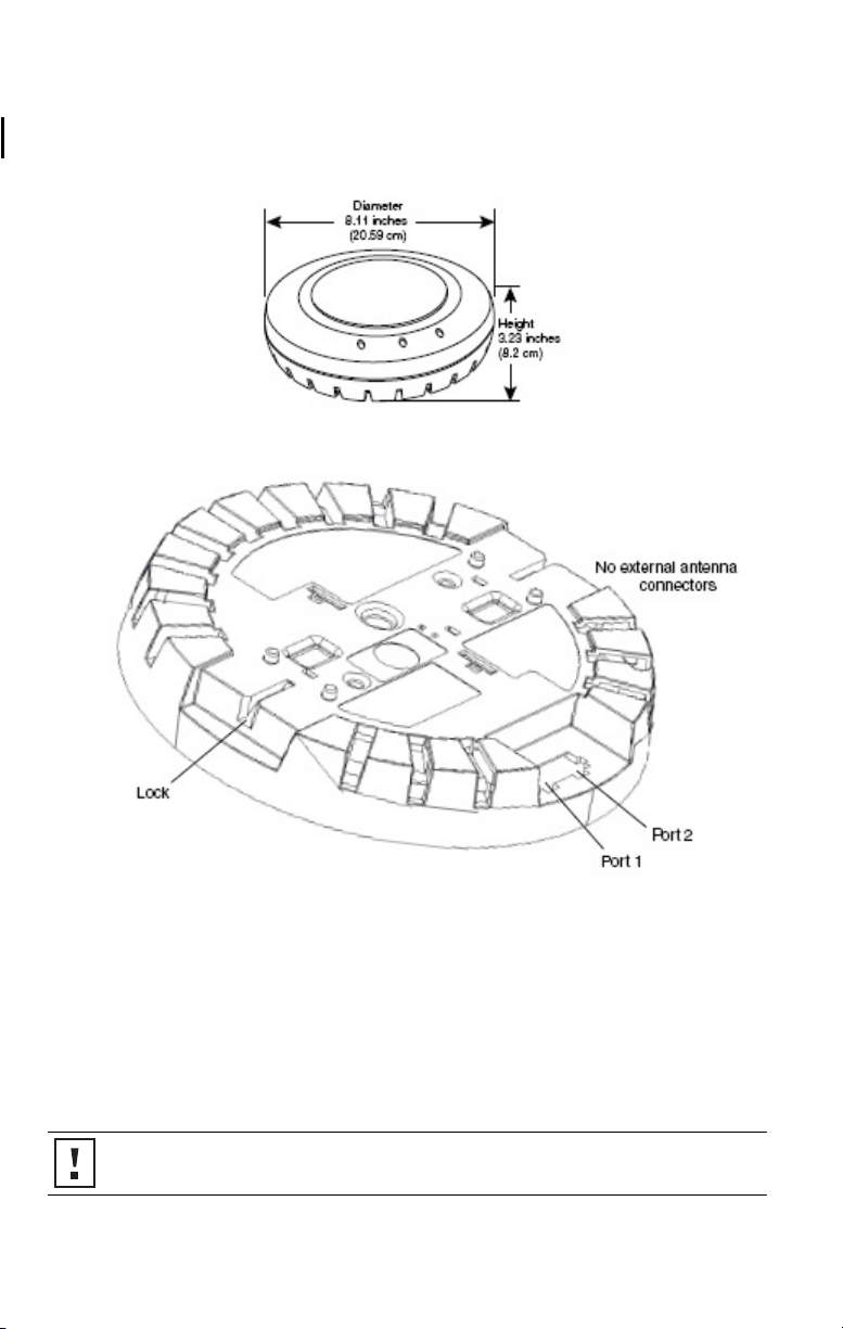
Kensington Security Slot
The access point has a slot for attachment of a Kensington security cable. The cable is not included with
the access point but can be ordered separately.
Lock and Unlock Holes
On one side of the access point there is a lock hole. On the other side there is an unlock hole. Insert a
3-mm or 1/8-inch screwdriver into the appropriate hole to attach and remove the access point from the
mounting bracket.
CAUTION: To prevent possible damage to the access point, do not use excessive force when
inserting a tool into the lock or unlock hole.
2
Page 5
RJ-45 Cable Ports
The access point has two RJ-45 ports. Each port provides a 10/100/1000BASE-TX Ethernet connection to
a WX controller. The connection can be direct to an WX controller or indirect through an intermediate
Layer 2 or Layer 3 network. For best performance, it is not recommend that the AP 3950 be connected
directly to the WXR100 or WX1200 wireless controller as these controllers only have 10/100 ports.
The access point receives power and data through the RJ-45 ports. Use a Category 5 (Cat 5) cable with
straight-through signaling and standard RJ-45 connectors to connect an access point to a controller in
the network.
The two RJ-45 ports support dual-homed configurations for redundancy. The access point uses only one
link for booting, configuration, and data transfer. If the link becomes unavailable, the access point can
reboot using the other link. This second port can also be used for supplying additional power. Since the
AP 3950 is a dual radio 802.11a/b/g/n access point, its power draw is slightly greater than what 802.3af
power can supply. When only a single 802.3af power connection is applied, the AP uses two
transmitters rather than all three (i.e. 2 x 3 MIMO). When dual 802.3af ports are used, the AP comes up
in full 3 x 3 MIMO mode for extended ranges. You can also power the AP via a single 802.3af+, also
known as pre-802.3at, switch or injector to get full 3 x 3 MIMO mode.
The ports are identical except for logical numbering (1 or 2). You can use either port to connect the
access point to a WX controller. However, the access point always attempts to boot on port 1 first. Only
if the boot attempt on port 1 fails does the access point attempt to boot on port 2. If one port becomes
unavailable, the other port can provide full power to the access point.
Note: The access point does not support daisy-chain configurations. Do not connect the access point
to another AP3950 access point.
Observing Safety Precautions
This equipment must be installed in compliance with local and national building codes, regulatory
restrictions, and FCC rules. For the safety of people and equipment, only professional network personnel
should install the access point
.\
WARNING: To comply with FCC radio frequency (RF) exposure limits, a minimum body-to-
antenna distance of 20 cm (8 inches) must be maintained when the access point is operational.
WARNING: To avoid possible injury or damage to equipment, you must use power supply equipment
that is safety certified according to UL, CSA, IEC, or other applicable national or international safety
requirements for the country of use. All references to power supply in this document refer to equipment
meeting these requirements.
WARNING: Do not operate the access point near unshielded blasting caps or in an otherwise
explosive environment unless the device has been modified for such use by qualified personnel.
WARNING: Do not touch or move the access point when the antennas are transmitting or receiving.
WARNING: Do not hold any radio device so that the antenna is very close to or touching the face,
eyes, or other exposed body part while the device’s radio antenna is transmitting.
3
Page 6
WARNING: Before using a wireless device in a hazardous location, consult the local codes, national
codes, and safety directors of the location for usage constraints.
WARNING: Do not connect or disconnect cables or otherwise work with the access point
hardware during periods of lightning activity.
NOTE: The access point is intended for indoor use only. Do not install the device outdoors,
unless you install it in a properly installed enclosure.
NOTE: To reduce the possibility of connection interference caused by dust, clean the
5 connector pins before inserting a cable into the access point.
Category
1 Unpacking the Access Point
Make sure that you have the following items, which are included with the access point:
• Mounting Kit:
• One universal mounting bracket (attached to the access point)
• One paper mounting template (used for marking cutting areas and screw holes)
• One two-piece 14.2-mm (9/16-inch) T-bar clamp
• One two-piece 15.9-mm (5/8-inch) T-bar clamp
• One two-piece 23.9-mm (15/16-inch) T-bar clamp
• Two #6 sheet metal screws and two drywall anchors
• Three adhesive rubber feet (used for a tabletop installation).
2 Preparing for Installation
It is advisable to connect the power (if using an external power supply) and check the Ethernet cables
and LEDs before installing the access
following before mounting or connecting the access point:
• Cabling Make sure that standard Category 5 cable with straight-through signaling is
installed at the site before you install the access point.
Make sure that the cable is highly flexible and that there is no extra covering
on the RJ-45 connector that could prevent the cable from being routed
through the mounting bracket
• Power Power must be supplied via an 802.3af Power Over Ethernet (PoE)-compliant
device. Removal of the Ethernet cable is the only method of disconnecting
power from the access point.
transmitters and three receivers (3 x 3 MIMO) in this dual radio 802.11a/b/g/n
Access Point, the AP 3950 power demands exceed the 802.3af power limits.
The AP 3950 has an auto-sense capability so that, when only 802.3af power
is supplied, it turns on in a 2 x 3 mode. When 802.3af+ (also known as pre-
802.3at) or two 802.3af ports are used, the AP 3950 comes up in full 3 x 3
mode.
point in a hard-to-reach location. Additionally, observe the
With the advanced functionality of three
4
Page 7

• MAC Address Record the access point MAC address in a safe place before the access point
is installed in a hard-to-reach location. The MAC address is printed on the
back of the access point. Additional MAC address labels are shipped with the
access point.
3 Mounting the Access Point
The access point can be mounted on the following types of surfaces:
• Suspended ceiling — flush ceiling tiles
• Suspended ceiling — drop ceiling tiles
• Junction box
• Solid wall or ceiling
• Tabletop
5
Page 8
Cable Requirement
U
840
9502
0008
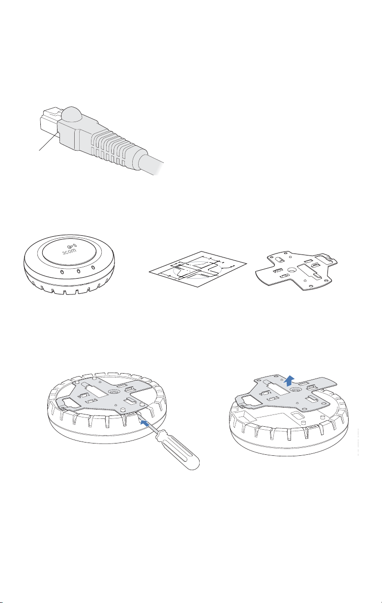
The Ethernet ports on the access point cannot accept a Category 5 cable that has an uneven sheath
such as the one shown in the figure below. The RJ-45 connector on the cable will not seat properly in
the receptacle on the access point. Use a Category 5 cable with an even sheath instead.
neven sheath
Suspended Ceiling — Flush Ceiling Tiles
This procedure applies to T-bars that are 23.9 mm (15/16 inches) wide. For a 14.2-mm (9/16-inch) or
15.9-mm (5/8-inch) T-bar, go to
M
T
“Suspended Ceiling Installation — Drop Ceiling Tiles” on page 8.
Mounting template Mounting bracket
Mobility
AP3950 access point
point
Mounting
template
1 Use the mounting template to cut a hole for the Category 5 cable.
2 Remove the mounting bracket from the access point.
840-9502-0011
6
Mounting
bracket
-
-
Page 9

3 Attach the mounting bracket to the T-bar clamp.
Universal mounting
bracket
T- b a r
Port connector
opening
(Viewed from above ceiling tiles, looking down.)
opening
840-9502-0005
Universal mounting bracketPort connector
T- b a r
4 Insert the Category 5 cable through the port connector opening in the mounting
bracket, then plug the cable into the access point.
TM
840-9502-0002
5 Attach the access point to the mounting bracket
Lock
T-bar
T
M
7
TM
40-9502-0006
Page 10

Suspended Ceiling Installation — Drop Ceiling Tiles
This procedure applies to T-bars that are 23.9 mm (15/16 inches), 14.2 mm (9/16 inches), or 15.9 mm
(5/8 inches) wide. You can also use this procedure for flush ceilings with 14.2-mm (9/16-inch) or 15.9mm (5/8-inch) T-bars.
M
T
Mobility
AP3950 access point
point
Mounting
Mounting template
template
T-bar clamps
T-b a r cl a mp s
(use set that fits T-bar)
(use set that fits T-bar)
1 Use the mounting template to cut a hole for the Category 5 cable.
2 Install the T-bar clamp that fits the T-bar.
T-bar
T-bar clamp halves
23.9-mm (15/16-in) or 14.2-mm (9/16-in) T-bar
(The clamps are different widths but the assembly is the same.)
T-bar
T-bar clamp halves
Slide together
840-9502-0003
Slide together
Mounting
Mounting
bracket
bracket
15.9-mm (5/8-in) T-bar
840-9502-0066
8
Page 11

3 Remove the mounting bracket from the access point.
t
840-9502-0011
840-9502-0008
4 Attach the mounting bracket to the T-bar clamp.
Universal mounting
bracket
T- bar
T-bar clamps
(attached
to T-bar)
Port connector
opening
(Viewed from above ceiling tiles, looking down.)
Port connector
opening
840-9502-0012
Universal mounting bracke
T- b a r
5 Insert the Category 5 cable through the port connector opening in the mounting
bracket, then plug the cable into the access point.
TM
840-9502-0002
9
Page 12

6 Attach the access point to the mounting bracket.
Lock
T-bar
T
M
Junction Box Installation
M
T
TM
840-9502-0006
Mobility
AP3950 access point
point
Mounting
bracket
bracket
1 Remove the mounting bracket from the access point.
840-9502-0011
10
Mounting hardwareMounting
Mounting hardware
840-9502-0008
Page 13

2 Attach the bracket to the junction box.
Junction box
Port connector
opening
840-9502-0017
3 Plug the Category 5 cable into the access point and attach the access point to the
mounting bracket.
M
T
TM
Lock
840-9502-0062
11
Page 14

Solid Wall or Ceiling Installation
M
T
Mobility
AP3950 access point Mounting
point
Mounting
template
template
Mounting
Mounting
bracket
bracket
1 Use the mounting template to cut a hole for the Category 5 cable.
2 Remove the mounting bracket from the access point.
840-9502-0011
3 Attach the bracket to the wall or ceiling.
Mounting
Mounting
hardware
hardware
840-9502-0008
M
T
840-9502-0015
12
Page 15

4 Plug the Category 5 cable into the access point and attach the access point to the
mounting bracket.
Cable
M
T
Universal mounting bracket
840-9502-0016
M
T
TM
Lock
840-9502-0062
13
Page 16

Tabletop Installation
M
T
Mobility
AP3950 access point
point
Mounting
Mounting
bracket
bracket
1 Remove the mounting bracket from the access point.
840-9502-0011
2 Reverse the bracket and reattach it to the access point.
840-9502-0061
3 Attach the rubber feet.
Rubber feet
Rubber feet
840-9502-0008
840-9502-0013
4 Turn the access point over and place it on the table.
5 Plug the Category 5 cable into the access point.
14
Page 17

4 Connecting the Access Point to a Controller
3Com recommends that you install and configure the 3Com Wireless LAN Controller before installing
the access point. If the controller is already installed and configured for the access point, you can
immediately verify the cable connection when you plug the cable into the access point.
WARNING: Do not connect or disconnect cables or otherwise work with the access point during
periods of lightning activity.
You can connect the access point directly to a 3Com Wireless LAN Controller port or indirectly to
Wireless LAN Controllers through an intermediate Layer 2 or Layer 3 network. In either case, use
3Com
Category 5 cable with straight-through signaling for each access point connection.
• To connect the access point directly to a 3Com Wireless LAN Controller, configure the
controller port as an AP3950 managed access point and then insert the cable into the
controller and verify the link.
• To connect the access point indirectly to a 3Com Wireless LAN Controller through the
network, configure a Distributed Access Point connection on the controller.
Note: You can use the CLI or 3WXM to configure an AP3950 access port or Distributed Access
Point connection. See the 3Com Wireless LAN Switch and Controller Configuration Guide or the
3Com Wireless LAN Switch Reference Manual
.
5 Configuring the Access Point
To configure the channels, power settings, and other access point parameters, see the following:
• “Configuring a WX Switch for Basic Service” chapter in the 3Com Wireless LAN Switch and
Controller Installation and Basic Configuration Guide.
• “Configuring MAP Access Points” chapter in the 3Com Wireless LAN Switch and Controller
Configuration Guide.
15
Page 18

6 Checking the LED Indicators
When the access point is connected to power, LEDs indicate activity as follows:
M
T
Radio 2 LED
Health LED
Radio 1 LED
840-9502-0010
LEDs Color Indicates
Health Solid green • The access point has a valid management link with a wireless
Solid amber The access point is waiting to receive boot instructions and a
Alternating green
and amber
Radio 1
(2.4 GHz)
Radio 2
(5.0 GHz)
Solid green A client is associated with the radio.
controller.
• The access point has booted.
• The access point has received a valid configuration from a
wireless controller.
• At least one radio is enabled or is in sentry mode on the access
point.
configuration file from a wireless controller.
The access point is booting and receiving its configuration file from a
wireless controller.
Blinking green Associated client is sending or receiving traffic.
Blinking amber Non-associated client is sending or receiving traffic.
Alternating green
and amber
The radio is unable to transmit. This state can occur because of any
of the following:
• Excessive radio interference in the environment is preventing
the radio from sending beacons.
• The radio has failed.
Unlit The radio is disabled.
If the radio is enabled, no clients are associated with the radio and
there is no traffic activity.
16
Page 19

Regulatory Information
The 3Com AP3950 Managed Access Point (3CRWX395075A) must be installed and used in strict accordance with the
manufacturer's instructions as described in the user documentation that comes with the product.
Note: This product contains encryption. It is unlawful to export out of the U.S. without obtaining a U.S. Export
License.
This product does not contain any user serviceable components. Any unauthorized product changes or modifications will
invalidate 3Com's warranty and all applicable regulatory certifications and approvals. This product must be installed by a
professional technician/installer.
CAUTION: EXPOSURE TO RADIO FREQUENCY RADIATION
This device generates and radiates radio-frequency energy. In order to comply with FCC radio-frequency exposure guidelines
for an uncontrolled environment, this equipment must be installed and operated while maintaining a minimum body-toantenna distance of 20 cm (approximately 8 in.).
The installer of this radio equipment must ensure that the antenna is located or pointed such that it does not emit RF field in
excess of Health Canada limits for the general population; consult Safety Code 6, obtainable from Health Canada's website
www.hc-sc.gc.ca/rpb.
This product must maintain a minimum body-to-antenna distance of 20 cm. Under these conditions this product will meet
the Basic Restriction limits of 1999/519/EC [Council Recommendation of 12 July 1999 on the limitation of exposure of the
general public to electromagnetic fields (0 Hz to 300 GHz)].
USA - RADIO FREQUENCY REQUIREMENTS.
This device must not be co-located or operated in conjunction with any other antenna or transmitter.
This device is for indoor use only when using channels 36, 40, 44 or 48 in the 5.15 to 5.25 GHz frequency range.
High power radars are allocated as primary users of the 5.25 to 5.35 GHz and 5.65 to 5.85 GHz bands. These radar stations
can cause interference with and/or damage this device.
USA-FEDERAL COMMUNICATIONS COMMISSION (FCC) EMC Compliance
This equipment has been tested and found to comply with the limits for a Class B digital device, pursuant to Part 15 of FCC
Rules. These limits are designed to provide reasonable protection against harmful interference in a residential installation.
This equipment generates, uses, and can radiate radio frequency energy. If not installed and used in accordance with the
instructions, it may cause harmful interference to radio communications. However, there is no guarantee that interference
will not occur in a particular installation. If this equipment does cause harmful interference to radio or television reception,
which can be determined by tuning the equipment off and on, the user is encouraged to try and correct the interference by
one or more of the following measures:
• Reorient or relocate the receiving antenna
• Increase the distance between the equipment and the receiver
• Connect the equipment to outlet on a circuit different from that to which the receiver is connected
• Consult the dealer or an experienced radio/TV technician for help
The user may find the following booklet prepared by the Federal Communications Commission helpful:
The Interference Handbook
This booklet is available from the U.S. Government Printing Office, Washington, D.C. 20402. Stock No. 004-000-0034504.
3Com is not responsible for any radio or television interference caused by unauthorized modification of the devices included
with this 3Com AP3950 Managed Access Point (3CRWX395075A), or the substitution or attachment of connecting cables
and equipment other than specified by 3Com.
The correction of interference caused by such unauthorized modification, substitution or attachment will be the
responsibility of the user.
Changes or modifications not expressly approved by 3Com could void the user’s authority to operate this equipment.
17
Page 20

MANUFACTURER'S FCC DECLARATION OF CONFORMITY
3Com Corporation
350 Campus Drive
Marlborough, MA 01752-3064, USA
(800) 527-8677
Date: May 6, 2005
Declares that the Product:
Brand Name: 3Com Corporation
Model Number: AP3950
Equipment Type: Managed Access Point
Complies with Part 15 of the FCC rules. Operation is subject to the following two conditions: (1) this device may not cause
harmful interference, and (2) this device must accept any interference received, including interference that may cause
undesired operation.
3Com AP3950 Managed Access Point
Model AP3950
INDUSTRY CANADA (IC) - RF Compliance
This device complies with RSS 210 of Industry Canada.
Operation is subject to the following two conditions: (1) this device may not cause interference, and (2) this device must
accept any interference, including interference that may cause undesired operation of this device.
L ' utilisation de ce dispositif est autorisée seulement aux conditions suivantes: (1) il ne doit pas produire de brouillage et (2)
l' utilisateur du dispositif doit être prêt à accepter tout brouillage radioélectrique reçu, même si ce brouillage est susceptible
de compromettre le fonctionnement du dispositif.
The term "IC" before the equipment certification number only signifies that the Industry Canada technical specifications
were met.
To reduce potential radio interference to other users, the antenna type and its gain should be so chosen that the equivalent
isotropically radiated power (EIRP) is not more than that required for successful communication. To prevent radio interference
to the licensed service, this device is intended to be operated indoors and away from windows to provide maximum
shielding. Equipment (or its transmit antenna) that is installed outdoors is subject to licensing.
Pour empêcher que cet appareil cause du brouillage au service faisant l'objet d'une licence, il doit être utilise a l'intérieur et
devrait être place loin des fenêtres afin de Fournier un écran de blindage maximal. Si le matériel (ou son antenne d'émission)
est installe a l'extérieur, il doit faire l'objet d'une licence.
High power radars are allocated as primary users of the 5.25 to 5.35 GHz and 5.65 to 5.85 GHz bands. These radar stations
can cause interference with and/or damage this device.
INDUSTRY CANADA (IC) EMISSIONS COMPLIANCE STATEMENT
This Class B digital apparatus complies with Canadian ICES-003.
AVIS DE CONFORMITÉ À LA RÉGLEMENTATION D'INDUSTRIE CANADA
Cet appareil numérique de la classe B est conform à la norme NMB-003 du Canada.
SAFETY COMPLIANCE NOTICE
This device has been tested and certified according to the following safety standards and is intended for use only in
Information Technology Equipment which has been tested to these or other equivalent standards:
• UL Standard 60950 (3rd Edition)
• CAN/CSA C22.2 No. 60950
• IEC 60950
• EN 60950
18
Page 21

EUROPE - EU DECLARATION OF CONFORMITY
This equipment may be operated in
AT BE CY CZ DK EE FI FR
DE GR HU IE IT LV LT LU
MT NL PL PT SK SI ES SE
GB IS LI NO CH BG RO TR
Intended use: IEEE 802.11a/b/g radio LAN device
NOTE: To ensure product operation is in compliance with local regulations, select the country in which the product is
installed. Refer to the Wireless LAN Mobility System, Wireless LAN Switch and Controller Configuration Guide.
EUROPE - DECLARATION OF CONFORMITY IN LANGUAGES OF THE EUROPEAN COMMUNITY
English Hereby, 3Com Corporation, declares that this RLAN device is in compliance with the essential
Finnish 3Com Corporation vakuuttaa täten että RLAN device tyyppinen laite on direktiivin 1999/5/EY
Dutch Hierbij verklaart 3Com Corporation dat het toestel RLAN device in overeenstemming is met de
French Par la présente 3Com Corporation déclare que l'appareil RLAN device est conforme aux exigences
Swedish Härmed intygar 3Com Corporation att denna RLAN device står I överensstämmelse med de
Danish Undertegnede 3Com Corporation erklærer herved, at følgende udstyr RLAN device overholder de
German Hiermit erklärt 3Com Corporation, dass sich dieser/diese/dieses RLAN device in Übereinstimmung
Greek ΜΕ ΤΗΝ ΠΑΡΟΥΣΑ 3Com Corporation ΔΗΛΩΝΕΙ ΟΤΙ RLAN device ΣΥΜΜΟΡΦΩΝ ΕΤΑΙ ΠΡΟΣ
Italian Con la presente 3Com Corporation dichiara che questo RLAN device è conforme ai requisiti
Spanish Por medio de la presente 3Com Corporation declara que el RLAN device cumple con los requisitos
requirements and other relevant provisions of Directive 1999/5/EC.
oleellisten vaatimusten ja sitä koskevien direktiivin muiden ehtojen mukainen.
essentiële eisen en de andere relevante bepalingen van richtlijn 1999/5/EG.
Bij deze verklaart 3Com Corporation dat deze RLAN device voldoet aan de essentiële eisen en aan
de overige relevante bepalingen van Richtlijn 1999/5/EC.
essentielles et aux autres dispositions pertinentes de la directive 1999/5/CE.
Par la présente, 3Com Corporation déclare que ce RLAN device est conforme aux exigences
essentielles et aux autres dispositions de la directive 1999/5/CE qui lui sont applicables.
väsentliga egenskapskrav och övriga relevanta bestämmelser som framgår av direktiv 1999/5/EG.
væsentlige krav og øvrige relevante krav i direktiv 1999/5/EF.
mit den grundlegenden Anforderungen und den anderen relevanten Vorschriften der Richtlinie
1999/5/EG befindet". (BMWi)
Hiermit erklärt 3Com Corporation die Übereinstimmung des Gerätes RLAN device mit den
grundlegenden Anforderungen und den anderen relevanten Festlegungen der Richtlinie 1999/5/EG.
(Wien).
ΤΙΕ ΟΥΣΙΩΔΕΙΣ ΑΠΑΙΤΗΣΕΙΣ ΚΑΙ ΤΙΣ ΛΟΙΠΕΣ ΣΧΕΤΙΚΕΣ ΔΙΑΤΑΕΕΙΣ ΤΗΣ ΟΔΗΠΑΣ 1999/5/
EK.
essenziali ed alle altre disposizioni pertinenti stabilite dalla direttiva 1999/5/CE.
esenciales y cualesquiera otras disposiciones aplicables o exigibles de la Directiva 1999/5/CE.
19
Page 22

Portuguese 3Com Corporation declara que este RLAN device está conforme com os requisitos essenciais e
Malti
Estonian Käesolevaga kinnitab 3Com Corporation seadme RLAN device vastavust direktiivi 1999/5/EÜ
Hungarian Alulírott, 3Com Corporation nyilatkozom, hogy a RLAN device megfelel a vonatkozó alapvetõ
Slovak
Czech
Slovene
Lithuanian
Latvian
A copy of the signed Declaration of Conformity can be downloaded from the Product Support web page for the AP3950
(3CRWX395075A) at http://www.3com.com.
outras disposições da Directiva 1999/5/CE.
Hawnhekk, 3Com Corporation, jiddikjara li dan RLAN device jikkonforma mal-htigijiet essenzjali u
ma provvedimenti ohrajn relevant li hemm fid-Dirrettiva 1999/5/EC.
põhinõuetele ja nimetatud direktiivist tulenevatele teistele asjakohastele sätetele.
követelményeknek és az 1999/5/EC irányelv egyéb elõírásainak.
3Com Corporation týmto vyhlasuje, ze RLAN device spåňa základné po_iadavky a všetky príslušné
ustanovenia Smernice 1999/5/ES.
3Com Corporation tímto prohlašuje, ze tento RLAN device je ve shodě se základními pozadavky a dalšími
příslušnými ustanoveními směrnice 1999/5/ES.
Šiuo 3Com Corporation deklaruoja, kad šis RLAN device atitinka esminius reikalavimus ir kitas 1999/5/EB
Direktyvos nuostatas.
Šiuo 3Com Corporation deklaruoja, kad šis RLAN device atitinka esminius reikalavimus ir kitas 1999/5/EB
Direktyvos nuostatas.
Ar šo 3Com Corporation deklarē, ka RLAN device atbilst Direktīvas 1999/5/EK būtiskajām prasībām un
citiem ar to saistîtajiem noteikumiem.
Also available at http://support.3com.com/doc/AP3950_EU_DOC.pdf
EUROPE - RESTRICTIONS FOR USE OF 2.4GHZ FREQUENCIES IN EUROPEAN COMMUNITY
COUNTRIES
This device may be operated indoors or outdoors in all countries of the European Community using the 2.4GHz band:
Channels 1 - 13, except where noted below.
• In Italy the end-user must apply for a license from the national spectrum authority to operate this device outdoors.
• In Belgium outdoor operation is only permitted using the 2.46 - 2.4835 GHz band: Channel 13.
• In France outdoor operation is only permitted using the 2.4 - 2.454 GHz band: Channels 1 - 7.
20
Page 23

EUROPE - RESTRICTIONS FOR USE OF 5GHZ FREQUENCIES IN EUROPEAN COMMUNITY
ç
COUNTRIES
Allowed Frequency Bands Allowed Channel Numbers Countries
5.15-5.25 GHz 36, 40, 44, 48 Austria
5.15-5.35 GHz 36, 40, 44, 48, 52, 56, 60, 64 Belgium, Cyprus, Czech Republic, France,
5.15-5.35 & 5.470-5.725GHz 36, 40, 44, 48, 52, 56, 60, 64, 100,
104, 108, 112, 116, 120, 124,
128, 132, 136, 140
• This device may be not be operated outdoors when using the bands 5150-5350MHz (Channels 36, 40, 44, 48, 52,
56, 50, 64).
• In Italy the end-user must apply for a license from the national spectrum authority to operate this device outdoors.
• To remain in conformance with European spectrum usage laws for Wireless LAN operation, the above 2.4GHz and
5GHz channel limitations apply. The user should check the current channel of operation. If operation is occurring
outside of the allowable frequencies as listed above, the user must cease operating the Managed Access Point at
that location and consult the local technical support staff responsible for the wireless network.
• The 5GHz Turbo mode feature is not allowed for operation in any European Community country.
• This device must be used with the radar detection feature required for European Community operation in the 5GHz
bands. This device will avoid operating on a channel occupied by any radar system in the area. The presence of
nearby radar operation may result in temporary interruption in communications of this device. The Access Point's
radar detection feature will automatically restart operation on a channel free of radar. You may consult with the local
technical support staff responsible for the wireless network to ensure the Access Point device(s) are properly
configured for European Community operation.
• Radio detection, as described above, is automatically enabled when the selected country of operation is within the
European Community.
• To reduce potential radio interference to other users, output power and antenna gain should be no higher than that
necessary for successful communication. The RF Auto-Tuning feature may be used to assist with this.
Hungary, Liechtenstein, Slovakia,
Switzerland
Bulgaria, Denmark, Estonia, Finland,
Germany, Greece, Iceland, Ireland, Italy,
Latvia, Lithuania, Luxembourg, Malta,
Netherlands, Norway, Poland, Portugal,
Slovenia, Spain, Sweden, U.K.
Brazil RF Compliance
Este equipamento opera em caráter secundário, isto é, năo tem d ire ito a p rot eçă o contra interf eręncia prejudicial,
mesmo de esta
őes do me smo tipo, e nă o causa r interferęnci a a sist em a operando em caráter primá rio.
21
Page 24

(1)「經型式認證合格之低功率射頻電機,非經許可,公司、商號或使用
者均不得擅自變更頻率、加大功率或變更原設計之特性及功能」警語以
及(2)「低功率射頻電機之使用不得影響飛航安全及干擾合法通信;經發
現有干擾現象時,應立即停用,並改善至無干擾時方得繼續使用。
(1)「經型式認證合格之低功率射頻電機,非經許可,公司、商號或使用
者均不得擅自變更頻率、加大功率或變更原設計之特性及功能」警語以
及(2)「低功率射頻電機之使用不得影響飛航安全及干擾合法通信;經發
現有干擾現象時,應立即停用,並改善至無干擾時方得繼續使用。前項
合法通信,指依電信法規定作業之無線電通信。低功率射頻電機須忍受
合法通信或工業、科學及醫療用電波輻射性電機設備之干擾」警語以及
(3)「5.25-5.35 GHz頻帶內操作之無線資訊傳輸設備,限於室內使用」警
語。
Copyright © 2008 3Com Corporation. All rights reserved. 3Com and the 3Com logo are registered trademarks of 3Com
Corporation. All other company and product names may be trademarks of the respective companies with which they
are associated.
Part Number 10016916, Rev. AA
Published July 2008
 Loading...