

Page 1
Quick Start Guide
3Com® WLAN Managed AP3150
3CRWX315075A / Model AP3150
The 3Com® AP3150 Managed Access Point provides dual-radio IEEE 802.11a and 802.11b/g
wireless access to the network. The access point is designed for use with a 3Com Wireless LAN
Switch, and requires hardware installation only. All configuration for the access point takes place
on the 3Com Wireless LAN Switch.
You must have a wireless switch device to operate the access point. The following WLAN switch
devices can be connected to the access point:
• 3Com WX4400
• 3Com WX2200
Power is supplied using Power Over Ethernet (PoE). The following 3Com PoE devices may be used
to supply power to the access point:
• 3Com PoE Injector
• 3Com 4400PWR PoE Switch
• 3Com Multi-port PoE power supply
• 3Com WX1200
• 3Com WXR100
• 3Com WX1200
• 3Com WXR100
• 3Com Baseline Switch 2426-PWR Plus
About This Guide
This Quick Start Guide describes the basic installation of the access point. It covers the following
topics:
• 3Com AP3150 Managed Access Point Features
• Observing Safety Precautions
• Step 1: Unpacking the Access Point
• Step 2: Preparing for Installation
• Step 3: Attaching the Antennas
• Step 4: Mounting the Access Point
• Step 5: Connecting the Access Point to a Switch
• Step 6: Checking the LED Indicators
• Troubleshooting
Page 2
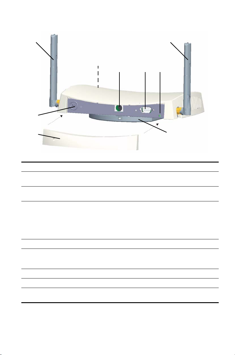
3Com AP3150 Managed Access Point Features
1
1
2
5
43
6
78
Feature Description
1 Antenna
Connectors
2 LEDs The LEDs indicate power and activity. See “Checking the LED
3 Ethernet Port The Ethernet port provides a 10/100BASE-TX Ethernet connection to a
4 Serial Port The serial port is not supported.
5 Reset Button To restore factory settings, press the reset button during power-up by
6 Kensington lock connector
7 Detachable rear-panel cover
8 Mounting Bracket The mounting bracket comes attached to the access point and allows
Two RSMA type antenna connectors allow you to connect antennas
that operate in 2.4
Indicators” on page 9 for details.
3Com Wireless LAN switch. The connection can be direct to a 3Com
switch or indirect through an intermediate Layer 2 or Layer 3 network.
Use a standard Category 5 cable with straight-through signaling and
standard RJ-45 connectors to connect the access point to the switch
on the network.
inserting a pointed object into the reset hole on the back of the access
point and holding for five seconds.
the unit to be mounted on a wall or ceiling.
GHz and 5.0 GHz bands.
2
Page 3

Observing Safety Precautions
This equipment must be installed in compliance with local and national building codes, regulatory
restrictions, and FCC rules. For the safety of people and equipment, only professional network
personnel should install the access point.
WARNING: Warnings contain directions that you must follow for your personal safety.
Follow all directions carefully.
You must read the following safety information carefully before you install or remove the unit.
WARNING: Exceptional care must be taken during installation and removal of the unit.
WARNING: The socket outlet must be near to the unit and easily accessible. You can
only remove power from the unit by disconnecting the power cord from the outlet.
WARNING: This unit operates under SELV (Safety Extra Low Voltage) conditions
according to IEC
to which it is connected also operates under SELV conditions.
WARNING: There are no user-replaceable fuses or user-serviceable parts inside the
unit. If you have a physical problem with the unit that cannot be solved with problem
solving actions in this guide, contact your supplier.
WARNING: Disconnect the power adapter before moving the unit.
WARNING: RJ-45 ports. These are shielded RJ-45 data sockets. They cannot be used
as standard traditional telephone sockets, or to connect the unit to a traditional PBX or
public telephone network. Only connect RJ-45 data connectors, network telephony
systems, or network telephones to these sockets.
Either shielded or unshielded data cables with shielded or unshielded jacks can be
connected to these data sockets.
WARNING: To comply with FCC radio frequency (RF) exposure limits, a minimum
body-to-antenna distance of 20 cm (8 in.) must be maintained when the access point is
operational.
950 / IEC 60950. The conditions are only maintained if the equipment
3
Page 4
Informacje na temat bezpieczeñstwa
Urządzenie musi być zamontowane zgodnie z lokalnymi i krajowymi normami, ustawami
i przepisami. W celu zagwarantowania bezpieczeństwa osób i urządzeń, instalację Punktu
dostępowęgo może przeprowadzać wyłącznie wyszkolony fachowiec ds. sieci.
OSTRZEŻENIE: Ostrzeżenia zawierają wskazówki, których należy przestrzegać
w celu zagwarantowania bezpieczeństwa osobistego. Do tych zaleceń należy
stosować się dokładnie.
Przed przystąpieniem do montażu lub demontażu urządzenia należy dokładnie przeczytać
następujące informacje dotyczące bezpieczeństwa.
OSTRZEŻENIE: Podczas montażu lub demontażu urządzenia należy pracować
z wyjątkową uwagą.
OSTRZEŻENIE: Gniazdo sieciowe powinno znajdować się w pobliżu urządzenia
i być łatwo dostępne. Z urządzenia można odciąć zasilanie wyłącznie poprzez
wyjęcie kabla zasilającego z gniazda.
OSTRZEŻENIE: Urządzenie działa w warunkach SELV (obwód bezpiecznego
niskiego napięcia) zgodnie z normą IEC
zagwarantowane wyłącznie wtedy, gdy sprzęt, do którego podłączone jest
urządzenie, również pracuje w obwodzie SELV.
OSTRZEŻENIE: Wewnątrz urządzenia nie znajdują się wymienne bezpieczniki lub
części, które mogłyby być oddane do naprawy. W przypadku wystąpienia problemu,
którego nie można rozwiązać za pomocą wskazówek podanych w tej instrukcji
obsługi, prosimy o kontakt z dostawcą produktu.
OSTRZEŻENIE: Przed przeniesieniem urządzenia należy odłączyć zasilacz.
OSTRZEŻENIE: Porty RJ-45. Są to ekranowane gniazda RJ-45 do danych. Nie są
przeznaczone do użycia jako standardowe gniazda telefoniczne lub do podłączenia
urządzenia do PBX lub publicznej sieci telefonicznej. Do tych gniazd wolno
podłączać wyłącznie wtyki RJ-45 danych, systemów telefonii sieciowej lub telefonów
sieciowych.
Do tych gniazd można podłączać kable danych ekranowane lub nieekranowane
z ekranowanymi lub nieekranowanymi wtykami.
OSTRZEŻENIE: W związku w ograniczeniami częstotliwości radiowej (RF),
minimalna odległość między ciałem a anteną wynosząca 20 cm (8 cali) musi być
zachowana w przypadku stosowania Punkt dostępowy.
950 / IEC 60950. Warunki te są jednak
4
Page 5

1. Unpacking the Access Point
Make sure that you have the following items, which are included with the access point:
• Two external 2.4 GHz and 5 GHz dual-band antennas
• Mounting bracket (attached to the access point)
• Wall-mounting hardware:
• Four adhesive rubber feet (used for a flat-surface installation).
2. Preparing for Installation
It is advisable to connect the power (if using an external power supply) and check the Ethernet
cables and LEDs before installing the access
observe the following items before mounting or connecting the access point:
Installation Item Description
Switch port 3Com recommends that you install and configure the 3Com Wireless
LAN switch before installing the access point. Set the port type on the
switch to an AP3150 access point.
Cabling Make sure that standard Category 5 cable with straight-through
signaling is installed at the site before you install the access point.
Make sure that the cable is highly flexible and that there is no extra
covering on the RJ-45 connector that could prevent the cable from
being routed through the mounting bracket.
Power Requirements Power must be supplied from an 802.3af Power Over Ethernet (PoE)-
compliant device.
If using an external PoE power injector, make sure the power outlet is
accessible. The power supply plug is the only means of disconnecting
the access point from power.
MAC Address Record the access point MAC address in a safe place before the access
point is installed in a hard-to-reach location.
The MAC address is printed on the back of the access point. Additional
MAC address labels are shipped with the access point.
point in a hard-to-reach location. Additionally,
5
Page 6

3. Attaching the Antennas
Carefully unpack the standard detachable antennas. Screw the antennas on to the antenna
connectors on the access point and hand-tighten them. After network startup, you may need to
adjust the antennas to fine-tune coverage in your area. For best results, adjust the antennas so
that they are perpendicular with the floor and ceiling.
CAUTION: Do not handle the antenna tips, especially after they are connected to the access
point. This could lead to electrostatic discharge (ESD), which could damage the equipment.
Connecting Optional External Antennas
The access point has connectors for attaching optional external antennas and antenna cables. The
tables below list the external antenna and cable models that are certified for use with the access
point.
Antenna Model Type
3CWE591 3Com 6/8 dBi Dual-Band Omnidirectional Antenna
3CWE592 3Com 3/4 dBi Dual Band Ceiling Antenna
3CWE597 3Com 6/8 dBi Dual-Band Hallway Antenna
3CWE598 3Com 8/10dBi Dual-Band Panel Antenna
Cable Model Type
3CWE580 3Com Ultra Low Loss 6-Foot Antenna Cable
3CWE581 3Com Ultra Low Loss 20-Foot Antenna Cable
3CWE582 3Com Ultra Low Loss 50-Foot Antenna Cable
3CWE586 3Com RSMA to SMA 6-inch Antenna Cable
Note 3CWE586 is required when using any of the external antennas
The 3Com antennas are dual-band, which means that they operate in both 2.4 GHz and 5 GHz
spectra. You can use these antennas with either the 802.11b/g radio or the 802.11a radio. Each
antenna requires the purchase of a separate antenna cable. For installation instructions, see the
documentation that is supplied with the antenna.
NOTE: Antenna cables introduce loss of the RF signal. Always use the shortest cable that
your application allows.
NOTE: During the installation, connect the antenna to the access point before connecting
the Category 5 Ethernet cable. This ensures that the access point is not powered on when
the antenna connections are made.
6
Page 7

4. Mounting the Access Point
The access point can be mounted on the following types of surfaces:
• Wall, ceiling, or electrical box (NEMA enclosure)
• Tabletop
Wall, Ceiling, or Electrical Box Mounting
Use the mounting bracket that comes with your access point to install it on a wall, ceiling, or
electrical box.
To wall-mount the access point:
1 Route Ethernet cable through the opening in the cradle.
2 Screw the mounting bracket to a wall, ceiling, or electrical box (NEMA enclosure):
• If mounting to a solid surface wall or ceiling, use the two sheet metal screws.
• If mounting to drywall, use the two sheet metal screws and two wall anchors.
• If mounting to an electrical box (NEMA enclosure), use the two threaded screws.
The figures below show a cable being routed through the large opening in the cradle and
then the cradle being mounted to a wall.
Wall-mounting the cradleRouting a cable
3 Connect the Ethernet cable (for power and network connection) to the port on the rear of
the access point.
4 Twist the access point onto the mounting bracket.
Tabletop Mounting
To install the access point on a flat surface such as a table or desktop:
1 Remove the backing from the four rubber feet and attach them on the bottom of the access
point.
2 Place the access point on the table.
3 Connect the Ethernet cable (for power and network connection) to the port on the rear of
the access point.
7
Page 8

5. Connecting the Access Point to a Switch
3CRWX120695A
Wir
el
ess LAN Swit
ch WX1200
TO ACCESS POINT
TO HUB/SWITCH
The access point can be powered by the following methods:
• By Power Over Ethernet (PoE) supplied over the LAN by a 802.3af PoE compliant device such
as a switch or hub.
• By PoE supplied by an optional 3Com PoE injector (not included). 3Com PoE injectors include
the 3CNJPSE and 3CNJPSE24 midspan supplies.
Power Over Ethernet (PoE) from the LAN
To power the access point using PoE provided by a switch or other 802.3af compliant device,
simply plug the network cable from the device into the access point’s Ethernet port.
PoE Switch/Hub
Access Point
Power Over Ethernet from a PoE Injector
To power the access point using the 3Com PoE Injector (available separately), do the following:
1 Connect the LAN cable from the switch or hub to the Hub/Switch port on the 3Com PoE
Injector (available separately).
2 Next connect a LAN cable from the Ethernet port on the access point to the other port on the
PoE injector.
3 Plug the PoE Injector into a properly grounded electric outlet.
PoE Injector
Access Point
To Access Point
To Switch/Hub
Switch/Hub
ch WX1200
LAN Swit
ess
Wirel
3CRWX120695A
(non-PoE)
8
Page 9

6. Checking the LED Indicators
When the access point is connected to power, LEDs indicate activity as follows:
LED Color Indicates
Power Green Power On
Amber Flashing indicates a hardware failure,
Off Power Off
11a Green Indicates that 802.11a 5 GHz wireless
Off The radio is off
11b/g Green Indicates that 802.11g 2.4 GHz
Off The radio is off
LAN Green Indicates a 10/100Base-T network is
Off No link
or the system is booting.
networking is enabled. If the LED is
flashing, the wireless link is OK and
data is being transmitted or received.
wireless networking is enabled. If the
LED is flashing, the wireless link is OK
and data is being transmitted or
received.
detected at the Ethernet port. If the
LED is flashing, the link is OK and
data is being transmitted or received.
Troubleshooting
Refer to the Mobility System Configuration Guide or to the 3Com Wireless LAN Switch Reference
Manual to obtain the access point status.
9
Page 10

10
Page 11

REGULATORY INFORMATION
The 3Com WLAN Managed AP3150, Model AP3150 (3CRWX315075A) must be installed and used in strict
accordance with the manufacturer’s instructions as described in the user documentation that comes with the
product.
This
prod
uct con
Li
cense.
i
This product does not contain any user serviceable components. Any unauthorized product changes or
modifications will invalidate 3Com’s warranty and all applicable regulatory certifications and approvals.
This product must be installed by a professional technician/installer.
Only antennas specified for your region by 3Com can be used with this product. The use of external amplifiers or
non-3Com antennas may invalidate regulatory certifications and approvals.
This product can be used with the following antennas and accessories:
Item Description Restrictions
— Supplied antenna
3CWE591 3Com 6/8dBi Dual-Band Omni Antenna Must be used with 3CWE586 and one of
3CWE592 3Com 3/4dBi Dual-Band Ceiling Mount
3CWE597 3Com 4/6dBi Dual-Band Hallway Antenna Must be used with 3CWE586 and one of
3CWE598 3Com 8/10dBi Dual-Band Panel Antenna Must be used with 3CWE586 and one of
3CWE580 3Com Ultra Low Loss 6-Foot Antenna Cable Must also use 3CWE586. Cannot be used
3CWE581 3Com Ultra Low Loss 20-Foot Antenna Cable Must also use 3CWE586. Cannot be used
3CWE582 3Com Ultra Low Loss 50-Foot Antenna Cable Must also use 3CWE586. Cannot be used
3CWE586 3Com RSMA to SMA 6-inch Antenna Cable Required for all external antennas, except
Suitable RF power levels for internal and external antennas are handled automatically by your 3Com Wireless
Switch or Controller. Ensure that the switch or controller configuration is modified to use the antenna that is
connected to the Access Point. Refer to the Mobility System Configuration Guide or to the 3Com Wireless LAN
Switch Reference Manual to modify the access point settings.
tains encrypti
Antenna
on. It is
unlawful to export out of the U.S. without obtaining a U.S. Export
the following: 3CWE580, 3CWE581 or
3CWE582.
Must be used with 3CWE586 and one of
the following: 3CWE580, 3CWE581 or
3CWE582.
the following: 3CWE580, 3CWE581 or
3CWE582.
the following: 3CWE580, 3CWE581 or
3CWE582.
with supplied antenna.
with supplied antenna.
with supplied antenna.
that supplied with the Access Point.
CAUTION: EXPOSURE TO RADIO FREQUENCY RADIATION
This device generates and radiates radio-frequency energy. In order to comply with FCC radio-frequency
exposure guidelines for an uncontrolled environment, this equipment must be installed and operated while
maintaining a minimum body to antenna distance of 20 cm (approximately 8 in.).
The installer of this radio equipment must ensure that the antenna is located or pointed such that it does not
emit RF field in excess of Health Canada limits for the general population; consult Safety Code 6, obtainable
from Health Canada’s website www.hc-sc.gc.ca/rpb.
This equipment complies with IC radiation exposure limits set forth for an uncontrolled environment. End users
must follow the specific operating instructions for satisfying RF exposure compliance. This equipment should be
installed and operated with minimum distance 20 cm between the radiator and your body.
This product must maintain a minimum body to antenna distance of 20 cm. Under these conditions this product
will meet the Basic Restriction limits of 1999/519/EC [Council Recommendation of 12 July 1999 on the limitation
of exposure of the general public to electromagnetic fields (0 Hz to 300 GHz)].
11
Page 12

US — RADIO FREQUENC Y REQUIREMENTS
This device must not be co-located or operated in conjunction with any other antenna or transmitter.
This device is for indoor use only when using channels 36, 40, 44 or 48 in the 5.15 to 5.25 GHz frequency range.
High power radars are allocated as primary users of the 5.25 to 5.35 GHz and 5.65 to 5.85 GHz bands. These
radar stations can cause interference with and/or damage this device.
FCC NOTICE
To comply with FCC Part 15 rules in the United States, the system must be professionally installed to ensure
compliance with the Part 15 certification. It is the responsibility of the operator and professional installer to
ensure that only certified systems are deployed in the United States. The use of the system in any other
combination (such as co-located antennas transmitting the same information) is expressly forbidden in
accordance with FCC rules CFR47 Part 15.204.
USA—FEDERAL COMMUNICATIONS COMMISSION (FCC) EMC COMPLIANCE
This equipment has been tested and found to comply with the limits for a Class B digital device, pursuant to Part
15 of the FCC Rules. These limits are designed to provide reasonable protection against harmful interference in
a residential installation. This equipment generates, uses and can radiate radio frequency energy and, if not
installed and used in accordance with the instructions, may cause harmful interference to radio communications.
However, there is no guarantee that interference will not occur in a particular installation. If this equipment does
cause harmful interference to radio or television reception, which can be determined by turning the equipment
off and on, the user is encouraged to try to correct the interference by one or more of the following measures:
• Reorient or relocate the receiving antenna.
• Increase the separation between the equipment and receiver.
• Connect the equipment into an outlet on a circuit different from that to which the receiver is connected.
• Consult the dealer or an experienced radio/TV technician for help.
The user may find the following booklet prepared by the Federal Communications Commission helpful: The
Interference Handbook. This booklet is available from the U.S. Government Printing Office, Washington, DC
20402. Stock No. 004-000-0034504.
3Com is not responsible for any radio or television interference caused by unauthorized modification of the
devices included with this 3Com WLAN Managed AP, Model AP3150 (3CRWX315075A), or the substitution or
attachment of connecting cables and equipment other than specified by 3Com.
The correction of interference caused by such unauthorized modification, substitution or attachment will be the
responsibility of the user.
Changes or modifications not expressly approved by 3Com could void the user's authority to operate this
equipment.
US MANUFACTURER’S FCC DECLARATION OF CONFORMITY
3C
om Corp
oration
35
0 Campus Dr
Marlborough,
(
508)
323-5000
Date: 1 March 2007
Declares that the Product:
Brand Name: 3Com Corporation
Model Number: AP3150
Equipment Type: WLAN Managed AP3150
Co
mplies with Part 15 of
e har
caus
caus
e undesired operation.
ive
MA 017
mful interferen
52-3064,
USA
the F
CC rules.
ce, and (2) this
Operation is subject to th
device must accept any interference received,
3Com WLAN Managed AP3150
Model AP3150
12
e foll
owi
ng two co
nditi
inclu
ons: (
1) this device may not
ding in
terference that may
Page 13

INDUSTRY CANADA — RF COMPLIANCE
This device complies with RSS 210 of Industry Canada.
Operation is subject to the following two conditions: (1) this device may not cause interference, and (2) this
device must accept any interference, including interference that may cause undesired operation of this device.
L’utilisation de ce dispositif est autorisée seulement aux conditions suivantes: (1) il ne doit pas produire de
brouillage et (2) l’utilisateur du dispositif doit étre prêt à accepter tout brouillage radioélectrique reçu, même si
ce brouillage est susceptible de compromettre le fonctionnement du dispositif.
The term “IC” before the equipment certification number only signifies that the Industry Canada technical
specifications were met.
To reduce potential radio interference to other users, the antenna type and its gain should be so chosen that the
equivalent isotropically radiated power (EIRP) is not more than that required for successful communication. To
prevent radio interference to the licensed service, this device is intended to be operated indoors and away from
windows to provide maximum shielding. Equipment (or its transmit antenna) that is installed outdoors is subject
to licensing.
Pour empecher que cet appareil cause du brouillage au service faisant l'objet d'une licence, il doit etre utilize a
l'interieur et devrait etre place loin des fenetres afin de Fournier un ecram de blindage maximal. Si le matriel (ou
son antenne d'emission) est installe a l'exterieur, il doit faire l'objet d'une licence.
High power radars are allocated as primary users of the 5.25 to 5.35 GHz and 5.65 to 5.85 GHz bands. These
radar stations can cause interference with and/or damage this device.
This device must not be co-located or operated in conjunction with any other antenna or transmitter.
The band 5150-5250 MHz is only for indoor usage to reduce the potential for harmful interference to cochannel mobile satellite systems.
This device has been designed to operate with the antennas listed at the start of the Regulatory Information
section above (page 11), and having a maximum gain of 8 dB (2.4 GHz) or 10 dB (5 GHz). Antennas not
included in this list or having a gain greater than 8 dB (2.4 GHz) or 10 dB (5 GHz) are strictly prohibited for use
with this device. The required antenna impedance is 50 ohms.
INDUSTRY CANADA - EMISSIONS COMPLIANCE STATEMENT
This Class B digital apparatus complies with Canadian ICES-003.
Avis de Conformité à la Réglementation d'Industrie Canada
Cet appareil numérique de la classe B est conform à la norme NMB-003 du Canada.
SAFETY COMPLIANCE NOTICE
This device has been tested and certified according to the following safety standards and is intended for use only
in Information Technology Equipment which has been tested to these or other equivalent standards:
• UL Standard 60950-1
• CAN/CSA C22.2 No. 60950-1
• IEC 60950-1
• EN 60950-1
EU COMPLIANCE
AT BE CY CZ DK EE FI FR
DE GR HU IE IT LV LT LU
MT NL PL PT SK SI ES SE
GB IS LI NO CH BG RO TR
Intended use: IEEE 802.11a/b/g radio LAN device
This equipment may be operated in
13
Page 14

NOTE: To ensure product operation is in compliance with local regulations, select the country in which the
product is installed.
Česky [Czech] 3Com Coporation tímto prohlašuje, že tento RLAN device je ve shodě se základ-
Dansk [Danish] Undertegnede 3Com Corporation erklærer herved, at følgende udstyr RLAN
Deutsch [German] Hiermit erklärt 3Com Corporation, dass sich das Gerät RLAN device in Überein-
Eesti [Estonian] Käesolevaga kinnitab 3Com Corporation seadme RLAN device vastavust direkti-
English Hereby, 3Com Corporation, declares that this RLAN device is in compliance with
Español [Spanish] Por medio de la presente 3Com Corporation declara que el RLAN device cum-
Ελληνική [Greek] ΜΕ ΤΗΝ ΠΑΡΟΥΣΑ 3Com Corporation ΔΗΛΩΝΕΙ ΟΤΙ RLAN device
Français [French] Par la présente 3Com Corporation déclare que l'appareil RLAN device est con-
Italiano [Italian] Con la presente 3Com Corporation dichiara che questo RLAN device è con-
Latviski [Latvian] Ar šo 3Com Corporation deklarē, ka RLAN device atbilst Direktīvas 1999/5/EK
Lietuvių [Lithuanian] Šiuo 3Com Corporation deklaruoja, kad šis RLAN device atitinka esminius reika-
Nederlands [Dutch] Hierbij verklaart 3Com Corporation dat het toestel RLAN device in overeenstem-
Malti [Maltese] Hawnhekk, 3Com Corporation, jiddikjara li dan RLAN device jikkonforma mal-
Magyar [Hungarian] Alulírott, 3Com Corporation nyilatkozom, hogy a RLAN device megfelel a vonat-
Polski [Polish] Niniejszym 3Com Corporation oświadcza, że RLAN device jest zgodny z zasad-
Português
[Portuguese]
Slovensko [Slovenian] 3Com Corporation izjavlja, da je ta RLAN device v skladu z bistvenimi zahtevami
Slovensky [Slovak] 3Com Corporation týmto vyhlasuje, že RLAN device spĺňa základné požiadavky
Suomi [Finnish] 3Com Corporation vakuuttaa täten että RLAN device tyyppinen laite on direkti-
Svenska [Swedish] Härmed intygar 3Com Corporation att denna RLAN device står I överensstäm-
ními požadavky a dalšími příslušnými ustanoveními směrnice 1999/5/ES.
device overholder de væsentlige krav og øvrige relevante krav i direktiv
1999/5/EF.
stimmung mit den grundlegenden Anforderungen und den übrigen einschlägigen
Bestimmungen der Richtlinie 1999/5/EG befindet.
ivi 1999/5/EÜ põhinõuetele ja nimetatud direktiivist tulenevatele teistele asjakohastele sätetele.
the essential requirements and other relevant provisions of Directive 1999/5/EC.
ple con los requisitos esenciales y cualesquiera otras disposiciones aplicables o
exigibles de la Directiva 1999/5/CE.
ΣΥΜΜΟΡΦΩΝΕΤΑΙ ΠΡΟΣ ΤΙΣ ΟΥΣΙΩΔΕΙΣ ΑΠΑΙΤΗΣΕΙΣ ΚΑΙ ΤΙΣ ΛΟΙΠΕΣ
ΣΧΕΤΙΚΕΣ ΔΙΑΤΑΞΕΙΣ ΤΗΣ ΟΔΗΓΙΑΣ 1999/5/ΕΚ.
forme aux exigences essentielles et aux autres dispositions pertinentes de la
directive 1999/5/CE.
forme ai requisiti essenziali ed alle altre disposizioni pertinenti stabilite dalla
direttiva 1999/5/CE.
būtiskajām prasībām un citiem ar to saistītajiem noteikumiem.
lavimus ir kitas 1999/5/EB Direktyvos nuostatas.
ming is met de essentiële eisen en de andere relevante bepalingen van richtlijn
1999/5/EG.
htigijiet essenzjali u ma provvedimenti ohrajn relevanti li hemm fid-Dirrettiva
1999/5/EC.
kozó alapvetõ követelményeknek és az 1999/5/EC irányelv egyéb elõírásainak.
niczymi wymogami oraz pozostałymi stosownymi postanowieniami Dyrektywy
1999/5/EC.
3Com Corporation declara que este RLAN device está conforme com os requisitos essenciais e outras disposições da Directiva 1999/5/CE.
in ostalimi relevantnimi določili direktive 1999/5/ES.
a všetky príslušné ustanovenia Smernice 1999/5/ES.
ivin 1999/5/EY oleellisten vaatimusten ja sitä koskevien direktiivin muiden
ehtojen mukainen.
melse med de väsentliga egenskapskrav och övriga relevanta bestämmelser
som framgår av direktiv 1999/5/EG.
14
Page 15

Íslenska [Icelandic] Hér með lýsir 3Com Corporation yfir því að RLAN device er í samræmi við
Norsk [Norwegian] 3Com Corporation erklærer herved at utstyret RLAN device er i samsvar med de
A copy of the signed Declaration of Conformity can be downloaded from the Product Support web page for the
3Com WLAN Managed AP3150, Model AP3150 (3CRWX315075A) at http://www.3com.com. Also available at
http://support.3com.com/doc/AP3150_EU_DOC.pdf
grunnkröfur og aðrar kröfur, sem gerðar eru í tilskipun 1999/5/EC.
grunnleggende krav og øvrige relevante krav i direktiv 1999/5/EF.
EU - RESTRICTIONS FOR USE IN THE 2.4 GHZ BAND
This device may be operated indoors or outdoors in all countries of the European Community using the 2.4 GHz
band: Channels 1–13, except where noted below.
•In Italy the end-user must apply for a license from the national spectrum authority to operate this device
outdoors.
•In Belgium outdoor operation is only permitted using the 2.46 – 2.4835 GHz band: Channel 13.
•In France outdoor operation is only permitted using the 2.4 – 2.454 GHz band: Channels 1 – 7.
EU - RESTRICTIONS FOR USE IN THE 5 GHZ BAND
Allowed Frequency Bands Allowed Channel Numbers Countries
5.15–5.35 & 5.470–5.725 GHz 36, 40, 44, 48, 52, 56, 60, 64, 100,
• This device may be not be operated outdoors when using the bands 5150–5350 MHz (Channels 36, 40, 44,
48, 52, 56, 50, 64).
• In Italy the end-user must apply for a license from the national spectrum authority to operate this device
outdoors.
• To remain in conformance with European spectrum usage laws for Wireless LAN operation, the above 5 GHz
channel limitations apply. The user should check the current channel of operation. If operation is occurring
outside of the allowable frequencies as listed above, the user must cease operating the Access Point at that
location and correct the configuration of the channels used before resuming operation.
• The 5 GHz Turbo mode feature is not allowed for operation in any European Community country.
• This device must be used with the radar detection feature required for European Community operation in the
5 GHz bands. This device will avoid operating on a channel occupied by any radar system in the area. The
presence of nearby radar operation may result in temporary interruption in communications of this device.
The Access Point's radar detection feature will automatically restart operation on a channel free of radar. You
may consult with the local technical support staff responsible for the wireless network to ensure the Access
Point device(s) are properly configured for European Community operation.
104, 108, 112, 116, 120, 124, 128,
132, 136, 140
Austria, Belgium, Bulgaria, Cyprus,
Czech Republic, Denmark, Estonia,
Finland, France, Germany, Greece,
Hungary, Iceland, Ireland, Italy,
Latvia, Liechtenstein, Lithuania,
Luxembourg, Malta, Netherlands,
Norway, Poland, Portugal, Romania,
Slovakia, Slovenia, Spain, Sweden,
Switzerland, U.K.
BRAZIL RF COMPLIANCE
Este produto está homologado pela ANATEL, de acordo com os procedimentos regulamentados pela Resolução
242/2000, e atende aos requisitos técnicos aplicados.
Opera em caráter secundário, isto é, não tem direito a proteção contra interferência prejudicial, mesmo de
estações do mesmo tipo, e não pode causar interferência a sistemas operando em caráter primário.
Para maiores informações, consulte o site da ANATEL - www.anatel.gov.br
15
Page 16

KOREA RF COMPLIANCE
This device may cause radio interference during its operation. Therefore service in relation to human life security
is not available.
TAIWAN RF COMPLIANCE
經型式認證合格之低功率射頻電機 , 非經許可 , 公司、商號或使用者均不得擅自變更頻率、加大功率或變更
原設計之特性及功能。低功率射頻電機之使用不得影響飛航安全及干擾合法通信 ; 經發現有干擾現象時 , 應
立即停用 , 並改善至無干擾時方得繼續使用。前項合法通信 , 指依電信法規定作業之無線電通信。低功率射
頻電機須忍受合法通信或工業、科學及醫療用電波輻射性電機設備之干擾。
CHINA ROHS
Copyright © 2007 3Com Corporation. All rights reserved. 3Com and the 3Com logo are registered
trademarks of 3Com Corporation. All other company and product names may be trademarks of the
respective companies with which they are associated.
Part Number: 10015915 Rev. AA
Published March 2007
 Loading...